


 Loading...
O P E R A T I N G A N D S E R V I C E M A N U A L
1300 MHz COUNTER
5305 B

CERTIFICATION
Hewlett-Packard Company certifies that this instrument met its published specifications at the time of shipment from the factory. Hewlett-Packard Company further certifies that its calibration measurements are traceable to the United States National Bureau of Standards, to the extent allowed by the Bureau's calibration facility, and to the calibration facilities of other International Standards Organization members.
WARRANTY AND ASSISTANCE
This Hewlett-Packard product is warranted against defects in materials and workmanship for a period of one year from the date of shipment. Hewlett-Packard will, at its option, repair or replace products which prove to be defective during the warranty period provided they are returned to Hewlett-Packard, and provided the preventive maintenance procedures in this manual are followed. Repairs necessitated by misuse of the product are not covered by this warranty. NO OTHER WARRANTIES ARE EXPRESSED OR IMPLIED, INCLUDING, BUT NOT LIMITED TO, THE IMPLIED WARRANTIES OF MERCHANTABILITY AND FITNESS FOR A PARTICULAR PURPOSE. HEWLETT-PACKARD IS NOT LIABLE FOR CONSEQUENTIAL DAMAGES.
Service contracts or customer assistance agreements are available for Hewlett-Packard products.
For any assistance, contact your nearest Hewlett-Packard Sales and Service Office. Addresses are provided at the back of this manual.

Model 5305B
Table of Contents
SECTION I XE
1300 MHz COUNTER
5305 B
OPERATING AND SERVICE MANUAL
SERIAL PREFIX: 1616A
This section applies directly to Model 5305B 1300 MHz Counters having Serial Prefix 1616A. This section is provided in loose-leaf form for incorporation into the 5300 Measurement System Manual. 5305A instruments are documented in a separate manual.
NEWER INSTRUMENTS
This section with enclosed "Manual Changes" sheet applies directly to HP Model 5305B 1300 MHz Counters having Serial Prefix numbers above 1616A.
OLDER INSTRUMENTS
Subsection VII of this document contains information pertinent to all older instruments.
Copyright |
HEWLETT-PACKARD COMPANY |
1976 |
5301 STEVENS |
CREEK BLVD., SANTA CLARA, CALIF. |
95050 |
Printed: AUG 1976
MANUAL PART NO. 05305-90008 |
|
MICROFICHE PART NO. 05305-90009 |
PRINTED IN U.S.A. |
|
|
|
|
Model 5305B |
|
|
|
Table of Contents |
|
|
TABLE OF CONTENTS |
|
Section |
|
|
Page |
I X E |
5305B 1300 MHz Counter |
|
|
Subsection |
|
|
|
I |
GENERAL INFORMATION ...................................................................................... |
9E-1-1 |
|
|
9E-1-1. |
Scope of Manual.................................................................................... |
9E-1-1 |
|
9E-1-3. |
Description ............................................................................................ |
9E-1-1 |
|
9E-1-6. |
Instrument Identification ....................................................................... |
9E-1-2 |
|
9E-1-8. |
Equipment Supplied .............................................................................. |
9E-1-2 |
|
9E-1-10. |
Accessories Available ........................................................................... |
9E-1-2 |
|
9E-1-12. |
5300A/5300B Compatibility. ... ............................................................ |
9E-1-2 |
|
9E-1-14. |
Specifications ........................................................................................ |
9E-1-2 |
|
9E-1-16. |
Recommended Test Equipment............................................................. |
9E-1-2 |
II |
INSTALLATION......................................................................................................... |
9E-2-1 |
|
|
9E-2-1. |
Unpacking and Inspection ..................................................................... |
9E-2-1 |
|
9E-2-3. |
Storage and Shipment............................................................................ |
9E-2-1 |
|
9E-2-6. |
Installation and Removal of Plug-On .................................................... |
9E-2-1 |
|
9E-2-8. |
Portable Operation................................................................................. |
9E-2-1 |
IIIOPERATION 9E-3-1
|
9E-3-1. |
Introduction ........................................................................................... |
9E-3-1 |
|
9E-3-3. |
Operating Characteristics ...................................................................... |
9E-3-1 |
|
9E-3-5. |
Input Channels.................................................................................... |
9E-3-1 |
|
9E-3-9. |
Resolution.............................................................................................. |
9E-3-1 |
|
9E-3-11. |
1300 MHz Channel Input Levels........................................................ |
9E-3-2 |
IV |
THEORY OF OPERATION ........................................................................................ |
9E-4-1 |
|
|
9E-4-1. |
Introduction ........................................................................................... |
9E-4-1 |
|
9E-4-3. |
A1 LogicBoard ...................................................................................... |
9E-4-1 |
|
9E-4-5. |
High Impedance Amplifier ................................................................. |
9E-4-1 |
|
9E-4-12. |
Counting Circuits................................................................................ |
9E-4-1 |
|
9E-4-16. |
Frequency Multiplier .......................................................................... |
9E-4-2 |
|
9E-4-30. |
1300 MHz ÷ Circuit............................................................................ |
9E-4-4 |
|
9E-4-32. |
A2 1300 MHz Amplifier Assembly……………………………………9E-4-4 |
|
V |
MAINTENANCE......................................................................................................... |
9E-5-1 |
|
|
9E-5-1. |
Introduction ........................................................................................... |
9E-5-1 |
|
9E-5-3. |
Recommended Test Equipment............................................................. |
9E-5-1 |
|
9E-5-5. |
In-Cabinet Performance Check ............................................................. |
9E-5-1 |
|
9E-5-7. |
Instrument Access ................................................................................. |
9E-5-1 |
|
9E-5-9. |
Periodic Maintenance ............................................................................ |
9E-5-1 |
|
9E-5-11. |
Maintenance and Repair ........................................................................ |
9E-5-1 |
|
9E-5-15. |
Adjustments........................................................................................... |
9E-5-5 |
|
9E-5-17. |
Channel A Adjustments......................................................................... |
9E-5-5 |
|
9E-5-19. |
Channel B Adjustments......................................................................... |
9E-5-6 |
|
9E-5-21. |
Troubleshooting..................................................................................... |
9E-5-6 |
|
9E-5-25. |
100 MHz Channel Troubleshooting ...................................................... |
9E-5-6 |
|
9E-5-27. |
1300 MHz Channel Troubleshooting .................................................... |
9E-5-7 |
|
9E-5-29. |
Both Channels Inoperative…………………………………………...9E-5-7 |
|
|
9E-5-34. |
Frequency Multiplier .......................................................................... |
9E-5-7 |
VI |
REPLACEABLE PARTS ............................................................................................ |
9E-6-1 |
|
|
9E-6-1. |
Introduction ........................................................................................... |
9E-6-1 |
|
9E-6-3. |
Ordering Information............................................................................. |
9E-6-1 |
iii
Model 5305B
Table of Contents
List of Tables and Figures
|
|
TABLE OF CONTENTS (Cont'd) |
|
Subsection |
|
|
Page |
VII |
MANUAL CHANGES .…….....................................................................................9E-7-1 |
||
|
9E-7-1. |
ManualChanges ................................................................................... |
9E-7-1 |
|
9E-7-3. |
NewerInstruments................................................................................ |
9E-7-1 |
VIII |
CIRCUIT DIAGRAMS.............................................................................................. |
9E-8-1 |
|
|
9E-8-1. |
Introduction.......................................................................................... |
9E-8-1 |
|
LIST OF TABLES |
|
Table |
|
Page |
9E-1-1. |
Specifications ............................................................................................................. |
9E-1-3 |
9E-1-2. |
Recommended Test Equipment.................................................................................. |
9E-1-4 |
9E-3-1. |
Resolution vs GateTime ............................................................................................. |
9E-3-1 |
9E-5-1. |
In-Cabinet Performance Check .................................................................................. |
9E-5-3 |
9E-5-2. |
Erroneous Displays Caused by U4 ............................................................................. |
9E-5-7 |
9E-6-1. |
Replaceable Parts ....................................................................................................... |
9E-6-3 |
9E-6-2. |
Manufacturers Code List ............................................................................................ |
9E-6-8 |
9E-8-1. |
Counter Signal List..................................................................................................... |
9E-8-1 |
|
LIST OF FIGURES |
|
figure |
|
Page |
9E-3-1. |
dBm-to-Voltage Conversions..................................................................................... |
9E-3-1 |
9E-3-2. |
Front Panel Controls, Connectors, and Indicators ...................................................... |
9E-3-2 |
9E-3-3. |
Self-Check Measurements.......................................................................................... |
9E-3-3 |
9E-3-4. 100 MHz Channel Frequency Measurements……………………………………….9E-3-4 |
||
9E-3-5. |
90 MHz-1300 MHz Channel Frequency Measurements ............................................ |
9E-3-5 |
9E-4-1. |
Phase Detector Block Diagram................................................................................... |
9E-4-2 |
9E-4-2. |
VCO Waveforms at about 2MHz ............................................................................... |
9E-4-3 |
9E-4-3. |
VCO Characteristics................................................................................................... |
9E-4-4 |
9E-5-1. |
Separation Procedure.................................................................................................. |
9E-5-2 |
9E-5-2. |
Test Setup for 1300MHz Adjustment......................................................................... |
9E-5-5 |
9E-6-1. |
Details of Input Connector J1 and Fuse Mounting………………………………….9E-6-8 |
|
9E-8-1. |
Channel B and Frequency Multiplier Circuits, Schematic Diagram .......................... |
9E-8-5 |
9E-8-2. Channel A and Logic Board Circuits, Schematic Diagram………………………….9E-8-9
iv

Model 5305B
General Information
SECTION I XE
5305B 1300 MHz COUNTER
SUBSECTION I
GENERAL INFORMATION
9E-1-1. SCOPE OF MANUAL
9E-1-2. This manual provides operating and service information for the Hewlett-Packard Model 5305B 1300 MHz Counter. Information for the mainframes (5300A or 5300B) is contained in separate manuals. This manual is divided into eight sections containing the following information:
SECTION 1 GENERAL INFORMATION covers a description of the counter, equipment supplied, accessories, specifications, and recommended test equipment.
SECTION II INSTALLATION provides instructions for unpacking, inspection, preparation for use, shipment, and storage for the counter.
SECTION III OPERATION covers the counter's operating features including front-panel controls, input level considerations, and operating and selfcheck procedures.
SECTION IV THEORY OF OPERATION describes the counter's theory of operation.
SECTION V MAINTENANCE contains an incabinet performance check, adjustments, and troubleshooting information.
SECTION VI REPLACEABLE PARTS provides a complete list of the counter's replaceable parts and information for ordering parts.
SECTION VII MANUAL CHANGES provides information necessary to backdate the manual to cover earlier instruments.
SECTION VIII SCHEMATIC DIAGRAMS THEORY contains schematic diagrams, and component locators.
9E-1-3. DESCRIPTION
9E-1-4. The 5305B extends the frequency measuring capability of the 5300 Measuring System to the UHF range. The counter features burst or CW measurements to 1300 MHz, separate channels to cover 90 MHz-1300 MHz and 50 Hz to 100 MHz both with 20 mV rms sensitivity, high resolution mode for fast tone measurements, automatic gain control for both channels or manual attenuator control for the high frequency channel, fuse protected high frequency channel, and probe power plus accessory preamp for high sensitivity applications. When operating in the high resolution mode, a phaselocked multiplier gives 1000 times improvement in the resolution of audio tone measurements. This feature is especially useful for servicing equipment using tone modulation for digital encoding on the carrier.
9E-1-1
Model 5305B General
Information
The 5305B is applicable to mobile communication bands in addition to VHF and UHF TV transmissions plus TACAN/DME and ATC radar transponders.
9E-1-5. The 10855A Preamplifier is available to boost the UHF sensitivity of the counter by a minimum of 22 dB.
9E-1-6. INSTRUMENT IDENTIFICATION
9E-1-7. Hewlett-Packard instruments have a 2-section, 10-character serial number (0000A00000) which is located on the rear panel. The 4-digit serial prefix identifies instrument changes. If the serial prefix of your instrument differs from that listed on the title page of this manual, there are differences between this manual and your instrument. Instruments having higher serial prefixes are covered with a "Manual Changes" sheet included with this manual. If the change sheet is missing, contact the nearest Hewlett-Packard Sales and Service Office listed at the back of this manual. Instruments having a lower serial prefix than that listed on the title page, are covered in the backdating Section VII.
9E-1-8. EQUIPMENT SUPPLIED
9E-1-9. The 5305B is supplied with an operating and service manual.
9E-1-10. ACCESSORIES AVAILABLE
9E-1-11. For high-sensitivity UHF applications, the 10855A Preamplifier can be used with the 5305B. The 10855A covers the 2 MHz to 1.3 GHz range with a gain of 22 dB minimum. Power requirements are +15 volts at ≈ 40 mA. The 5305B has a front-panel connector to supply the required + 15 volts to 10855A.
9E-1-12. 5300A/5300B COMPATIBILITY
9E-1-13. The 5305B is fully compatible with either the 5300A or the 5300B mainframe. Unlike the 5305A, a highstability time base is not available for the 5305B, however a high-stability time base is available for the 5300B.
9E-1-14. SPECIFICATIONS
9E-1-15. Specifications are listed in Table 9E-1-1.
9E-1-16. RECOMMENDED TEST EQUIPMENT
9E-1-17. Test equipment recommended for testing, calibration, and repair of the 5305B is listed in Table 1-2.
9E-1-2

Model
5305B General
Table 9E-1-1. Specifications
INPUT CHANNEL A (CW OR BURST)
Range: 90 MHz to 1300 MHz, prescaled by 16
Sensitivity: 20 mV rms
Impedance: 50Ω
Attenuator: Continuously variable to give optimum noise suppression for signals up to 3.5V rms.
Overload Protection: 5V rms, maximum. Input circuitry is fuse protected; fuse is located in BNC connector and is accessible from the front panel.
Operating Dynamic Range: > 47 dB
INPUT CHANNEL B (NORMAL AND HIGH RESOLUTION MODE)
Range: 50 Hz to 100 MHz, direct count in normal mode. 50 Hz to 10 kHz in high resolution mode. In the high resolution mode, the 5305B uses a phaselocked multiplier to increase resolution X1000 over normal measurement resolution.
Sensitivity: 20 mV rms
Impedance: 1 MΩ shunted by less than 40 pF.
Overload Protection: 250V rms from 50 Hz to 10 kHz, declining to 10V rms above 10 MHz.
Search Indicator: In high-resolution mode the "S" annunciator is lit whenever the input is beyond the proper frequency range, or too weak to measure, or during the brief acquisition time following signal interruption.
Automatic Hold: In high-resolution mode, the last valid reading is held in display when input is terminated.
FREQUENCY MEASUREMENT
RESOLUTION (SELECTABLE):
Normal Mode (50 Hz to 1300 MHz): 0.1 Hz to 10000 Hz in decade steps corresponding to gate times of 10 sec to 0.0001 sec in decade steps on channel B and to gate times of 160 s to .0016 s in decade steps on channel A.
High Resolution Mode (50 Hz to 10 kHz): 0.0001, 0.001, 0.01, 0.1, 1, 10 Hz corresponding to 10, 1, 0.1, 0.01, 0.001, 0.0001 second gate times on channel B.
Accuracy: ±1 digit displayed ± time base accuracy.
Display: Hz, kHz, MHz with positioned decimal point.
GENERAL
Check: Counts internal 10 MHz reference frequency to check counting circuits.
Operating Temperature: 0° to 50°C.
Power Requirements: Nominally 12 watts including mainframe.
Weight: Net 1.0 kg (2-1/4 lbs.); Shipping 1.8 kg (4 lbs.)
Dimensions: With mainframe, 89 mm H (3-1/2")x 160 mm W (6-1/4") x 248 mm L (9-3/4").
Compatible Mainframes: 5300A (6 digits) or 5300B (8 digits). 5300B is recommended.
Accessories: 10855A Preamp (22 dB gain).
9E-1-3
Model 5305B General
Information
Table 9E-1-2. Recommended Test Equipment
Instrument |
Required Characteristics |
Recommended Type |
Oscilloscope |
50 MHz Bandwidth |
HP 180A |
Vertical Plug-In |
50 mV/div Sensitivity |
HP 1801A |
Time Base Plug-In |
50 MHz Bandwidth |
HP 1821A |
Sampling Plug-In |
1000 MHz |
HP 1810A |
Optical Sampling Plug-In |
If desired to measure up to 1300 MHz |
HP 1811A/1432A |
Synthesized Signal Generator |
1300 MHz |
HP 8660B/86602A |
Power Meter |
-30 dBm to + 10 dBm |
HP 435A |
Power Sensor |
90 MHz to 1300 MHz |
HP 8481A |
Test Oscillator |
50 Hz to 10 MHz 3V rms |
HP 651B |
Mainframe |
|
HP 5300B |
Digital Voltmeter |
-5V to +20 V dc |
HP 5306A |
Power Splitter |
50 ohms 90 MHz to 1300 MHz |
HP 11667A |
Scope Probe |
10:1 1 MegΩ |
HP 10004D |
|
|
|
9E-1-4
Model 5305B
Installation
SECTION IX E
5305B 1300 MHz COUNTER
SUBSECTION II
INSTALLATION
9E-2-1. UNPACKING AND INSPECTION
9E-2-2. If the shipping carton is damaged, ask that the carrier's agent be present when the instrument is unpacked. Inspect the instruments for damage, such as scratches, dents, broken knobs, etc. If the instrument is damaged or fails to meet performance tests when used with the 5300B Measuring System, notify the carrier and the nearest Hewlett-Packard Sales and Service Office immediately. Performance check procedures are located in Section IX E- 5, and Sales and Service Offices are listed in Section VI of the 5300B portion of the manual. Retain the shipping carton and the padding material for the carrier's inspection. The Sales and Service Office will arrange for the repair or replacement of the instrument without waiting for the claim against the carrier to be settled.
9E-2-3. STORAGE AND SHIPMENT
9E-2-4. PACKAGING. To protect valuable electronic equipment during storage and shipment, always use the best packaging methods available. Your HewlettPackard Sales and Service Office can provide packaging material, such as that used for original factory packaging. Contract packaging companies in many cities can provide dependable custom packaging on short notice. Here is one recommended packaging method:
a. The original container is a corrugated cardboard box with 200 lbs. burst test (HP Part No. 9211-1620). The instrument is secured and protected, while in the box, by a
top and bottom molded frame of polystyrene (HP Part No. 9220-1545). Also included with the instrument is a plastic dust-protection cover (HP Part No. 9220-1762).
9E-2-5. ENVIRONMENT. Conditions during storage and shipment should be normally limited as follows:
a.Maximum altitude: 25,000 ft.
b.Minimum temperature: -40°F( -40°C).
c.Maximum temperature: +167°F(+75°C).
9E-2-6. INSTALLATION AND REMOVAL OF PLUG-ON
9E-2-7. The 5305B 1300 MHz Counter must be used with a mating 5300A or B Measuring System, before any measurements can be made. To mate the 5305B 1300 MHz Counter with a 5300 Measuring System, see Figure 2-1 and Paragraph 2-11 in the 5300 portion of the manual.
9E-2-8 PORTABLE OPERATION.
9E-2-9. The use of the HP Model 5310A Battery Pack enables the 5300 Measuring System and 5305B 1300 MHz Counter to be used in areas removed from ac power sources. The 5310A Battery Pack typically provides 5 hours of portable operating time before recharging. Tables 1-2 and 1-4 in 5300 portion of the manual lists the HP 5310A Battery Pack as an available accessory. Documentation on the 5310A is also included in Section IV through VIII of the 5300 portion of the manual. To prepare the 5300/5305B for portable operation, refer to Paragraph 2-13 and Figure 2-2 in the 5300 portion of the manual.
9E-2-1
Model 5305B
Operation
SECTION IX E
5305B 1300 MHz COUNTER
SUBSECTION III
OPERATION
9E-3-1. INTRODUCTION
9E-3-2. This section covers operating information for the 5305B including a description of controls, indicators, and connectors, resolution, input levels, and operating procedures for frequency measurements and self check.
9E-3-3. OPERATING CHARACTERISTICS
9E-3-4. The 5305B Counter performs frequency measurements by means of two separate input channels. These channels provide a combination of low frequency measurements and high-sensitivity, high frequency measurements. Measurement capability is applicable to all frequencies in the VHF and mobile communication bands in addition to a significant portion of the UHF band. The 10855A Preamplifier can be used to boost the UHF input sensitivity by 22 dB.
9E-3-5. Input channels
9E-3-6. Two input channels are provided, Channel A - 90 MHz to 1300 MHz and Channel B - 50 Hz to 100 MHz. Both channels have 20 mV rms sensitivity.
9E-3-7. Channel A prescales the input frequency by 16 and can be used to measure CW or burst signals. Input coupling is ac. An AGC circuit is included to give a dynamic range of >47 dB. An internal fuse, located inside the input jack, protects circuitry from overloads greater than 5V rms. Note that a blown fuse may not prevent the counter from measuring high-frequency inputs. In this instance, the counter’s circuitry is no longer protected,ie.,as it would be at lower frequencies by a good open circuit. If the fuse blows, a replacement fuse is supplied with the instrument.
9E-3-8. The frequency range of Channel B depends on the mode of operation - normal or high resolution. In the normal mode, Channel B covers 50 Hz to 100 MHz. With high-resolution selected, Channel B covers 50 Hz to 10 kHz. The high resolution mode uses a phase-locked multiplier to increase resolution by a factor of 1000. Input impedance is 1 Megohm shunted by less than 40 pF. A 10 to 1 divider probe can be used to increase the input impedance to 10 Megohms.
9E-3-9. RESOLUTION
9E-3-10. The 5305B has a RESOLUTION switch which determines the least-significant digit (LSD) displayed. For example, with an input of 123,456 Hz, setting the RESOLUTION switch to 1 kHz places the "3" in the LSD. Setting the switch to 10 Hz, places the "5" in the LSD. Resolution can be expressed in terms of the counter's gate time, as shown in Table 9E-3-1.
Table 9E-3-1. Resolution vs Gate time
RESOLUTION |
GATE TIME |
|
|
80 MHz |
1100 MHz |
.1 Hz |
10 s |
160 s |
1 Hz |
1 s |
16 s |
10 Hz |
.1 s |
1.6 s |
100Hz |
.01s |
.16s |
1 kHz |
1 ms |
16 ms |
10 kHz |
.1 ms |
1.6 ms |
|
|
|
Figure 9E-3-1. dBm-to-Voltage Conversions
9E-3-1
Model 5305B
Operation
9E-3-11. 1300 MHz Channel Input Levels
9E-3-12. The 1300 MHz channel is a 50-ohm system with a maximum input of 5V rms. Figure 9E-3-1 provides a conversion scale for determining respective levels of
voltage, power, and dBm. This scale applies to a 50-ohm system and is not applicable to the 100 MHz channel. The shaded area represents the specified operating range of the 1300 MHz channel.
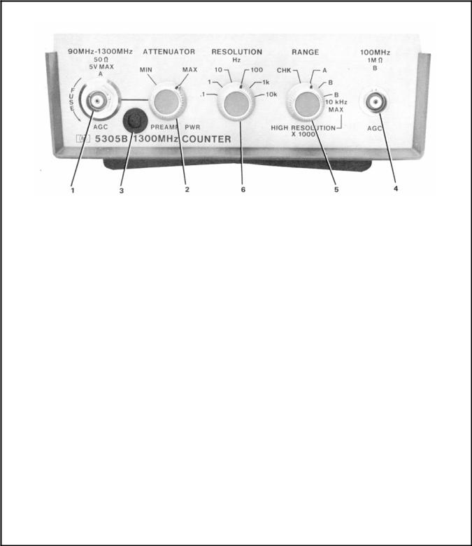
Figure 9E-3-2. Front Panel Controls, Connectors, and Indicators
NOTE
The "S" annunciator on the 5300 lights during the high-resolution mode whenever the input is beyond the proper frequency range, or too weak to measure, or during acquisition following signal interruption.
1.90 MHz - 1300 MHz Input Jack. With RANGE switch set to A, accepts input frequencies from 90 MHz to 1300 MHz. Input sensitivity is 20mV. 50 ohm input impedance and ac coupled. Maximum input is 5V rms. Fuse is located inside jack. Use a BNC connector as a wrench to remove and tighten the fuse jack. Replacement HP part number for fuse is 2110-0301.
2.ATTENUATOR Control. Provides manual control of input attenuator circuit for 1300 MHz channel. MIN position provides minimum signal attenuation. MAX position provides maximum attenuation. AGC circuit gives >47 dB dynamic range.
3.PREAMP POWER. Supplies + 15V @ ≈ 40 mA to power 10855A Preamplifier.
4.100 MHz Input Jack. When RANGE is set to B,
accepts input frequencies from 50 Hz to 100 MHz. With RANGE set to B HIGH RESOLUTION, accepts frequencies up to 10 kHz. Input sensitivity is 20 mV rms. Input impedance is 1 Megohm shunted by less than 40 pF. Channel is ac coupled.
5.RANGE switch. Allows selection of either of the two input channels or the self-check mode. In the CHK position, allows system to count the internal 10 MHz clock signal. Measurement is not affected by signals connected to the input jacks.
6.RESOLUTION Switch. The counter's leastsignificant digit displays the measured resolution of the input signal that is selected with the switch. For example, 10 Hz selected with 6,789 Hz input frequency: counter displays 6.78 kHz.
9E-3-2

Model 5305B
Operation
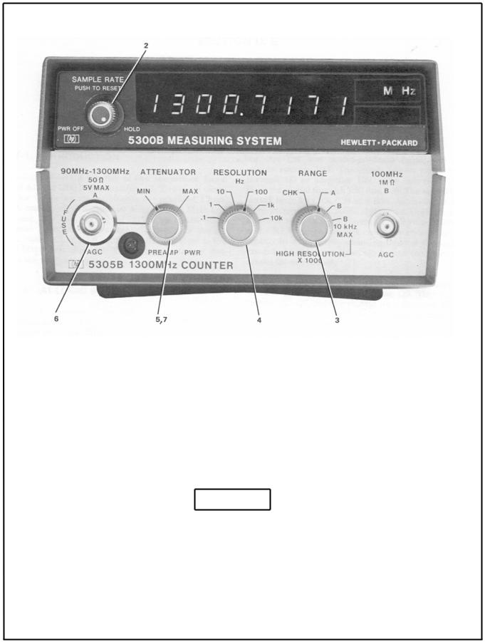
Figure 9E-3-3. Self-Check Measurements
1.Apply input power to 5300 ac receptacle.
2.Turn counter on with 5300 SAMPLE RATE control. Adjust SAMPLE RATE for minimum display time (full ccw).
3.Set RANGE switch to CHK position. Display is a function of RESOLUTION switch.
|
5300A Self Check |
5300B Self Check |
||
Resolution |
|
|
|
|
|
|
|
|
|
Selector |
Display |
Annunciator |
Display |
Annunciator |
|
|
|
|
|
10 kHz |
0010.00 |
M, Hz |
000010.00±1 |
M, Hz |
1 kHz |
010.000 |
M, Hz |
00010.000±1 |
M, Hz |
100 Hz |
10.0000 |
M, Hz, C |
0010.0000±1 |
M, Hz, C |
10 Hz |
0.00000 |
M, Hz, C |
010.00000±1 |
M, Hz, C |
1 Hz |
●000.000 |
K, Hz, C |
10000.000±1 |
K, Hz, C |
.1 Hz |
●00.0000 |
K, Hz, C |
0000.0000±1 |
K, Hz, C |
|
|
|
|
|
●Indicates overflow light is on.
9E-3-3

Model 5305B
Operation
Figure 9E-3-4. 100 MHz Channel Frequency Measurements
1.Apply power to 5300 ac receptacle.
2.Turn counter on with 5300 SAMPLE RATE control.
3.Set RANGE switch to B position.
4.Connect input signal to 100 MHz jack.
5.Set RESOLUTION switch for number of digits desired in display.
6.Adjust SAMPLE RATE control for convenient interval between measurements.
7.For high resolution, set RANGE switch to B 10 kHz MAX - HIGH RESOLUTION X1000. This limits the input frequency to 10 kHz but gives resolution up to 4 decimal places.
9E-3-4
Model 5305B
Operation
Figure 9E-3-5. 90 MHz -1300 MHz Channel Frequency Measurements
1.Apply input power to ac receptacle.
2.Turn counter on with 5300 SAMPLE RATE control.
3.Set RANGE switch to A position.
4.Set RESOLUTION switch to 10K.
5.Set ATTENUATOR control to MIN position.
CAUTION
Input level must not exceed 5V rms.
6.Connect input signal to 90 MHz -1300 MHz jack.
7.Adjust ATTENUATOR control until counter stops displaying, then back again until counter gives a stable display of the proper frequency.
9E-3-5
Loading...