


 Loading...
HP ProCurve 3500, 3500yl and 6200yl Switches
Installation and Getting Started Guide
Power over Ethernet

HP ProCurve 3500, 3500yl and
6200yl Switches
Installation and Getting Started Guide

© Copyright 2005, 2008-2009 Hewlett-Packard Development Company,
L.P. The information contained herein is subject to change without notice.
This document contains proprietary information, which is protected by copyright. No part of this document may be photocopied, reproduced, or translated into another language without prior written consent of Hewlett-Packard.
Publication Number
5900-0230 June 2009
Applicable Products
3500-24 Switch |
J9470A |
|
|
3500-48 Switch |
J9472A |
|
|
3500-24-PoE Switch |
J9471A |
|
|
3500-48-PoE Switch |
J9473A |
|
|
3500yl-24G-PWR Intelligent Edge |
J8692A |
|
|
3500yl-48G-PWR Intelligent Edge |
J8693A |
|
|
Switch 6200yl-24G mGBIC Premium Edge |
J8992A |
|
|
Switch 3500yl 2p 10GbE X2 + 2p CX4 Module |
J8694A |
|
|
620 Redundant and External Power Supply |
J8696A |
|
|
Switch 3500yl/6200yl Fan Tray |
5069-8598 |
|
|
Switch 3500yl/6200yl Rack Mounting Kit |
5069-5705 |
|
|
Switch 3500yl/6200yl 10K Rack Rail Kit |
356578-B21 |
|
|
Switch zl and yl RPS/EPS Cable |
5070-0102 |
|
|
Trademark Credits
Windows®, and MS Windows® are US registered trademarks of Microsoft Corporation.
Disclaimer
HEWLETT-PACKARD COMPANY MAKES NO WARRANTY OF ANY KIND WITH REGARD TO THIS MATERIAL, INCLUDING, BUT NOT LIMITED TO, THE IMPLIED WARRANTIES OF MERCHANTABILITY AND FITNESS FOR A PARTICULAR PURPOSE. Hewlett-Packard shall not be liable for errors contained herein or for incidental or consequential damages in connection with the furnishing, performance, or use of this material.
The only warranties for HP products and services are set forth in the express warranty statements accompanying such products and services. Nothing herein should be construed as constituting an additional warranty. HP shall not be liable for technical or editorial errors or omissions contained herein.
Hewlett-Packard assumes no responsibility for the use or reliability of its software on equipment that is not furnished by Hewlett-Packard.
Warranty
See the Customer Support/Warranty booklet included with the product.
A copy of the specific warranty terms applicable to your Hewlett-Packard products and replacement parts can be obtained from your HP Sales and Service Office or authorized dealer.
Safety
Before installing and operating these products, please read the “Installation Precautions” in chapter 2, “Installing the Switch”, and the safety statements in appendix C, “Safety and EMC Regulatory Statements”.
Hewlett-Packard Company
8000 Foothills Boulevard, m/s 5552 Roseville, California 95747-5552
http://www.procurve.com

Contents
1 Introducing the Switch
Front of the Switches . . . . . . . . . . . . . . . . . . . . . . . . . . . . . . . . . . . . . . . . . . . . 1-5
Network Ports . . . . . . . . . . . . . . . . . . . . . . . . . . . . . . . . . . . . . . . . . . . . . . 1-8
LEDs . . . . . . . . . . . . . . . . . . . . . . . . . . . . . . . . . . . . . . . . . . . . . . . . . . . . . 1-10
LED Mode Select Button and Indicator LEDs . . . . . . . . . . . . . . . . . . . 1-12
Reset Button . . . . . . . . . . . . . . . . . . . . . . . . . . . . . . . . . . . . . . . . . . . . . . 1-14
Clear Button . . . . . . . . . . . . . . . . . . . . . . . . . . . . . . . . . . . . . . . . . . . . . . . 1-14
Expansion Module LEDs . . . . . . . . . . . . . . . . . . . . . . . . . . . . . . . . . . . . 1-15
Back of the Switch . . . . . . . . . . . . . . . . . . . . . . . . . . . . . . . . . . . . . . . . . . . . . 1-16
yl Module Slot . . . . . . . . . . . . . . . . . . . . . . . . . . . . . . . . . . . . . . . . . . . . . 1-18
RPS and EPS Input Port . . . . . . . . . . . . . . . . . . . . . . . . . . . . . . . . . . . . . 1-19
Console Port . . . . . . . . . . . . . . . . . . . . . . . . . . . . . . . . . . . . . . . . . . . . . . 1-19
Power Connector . . . . . . . . . . . . . . . . . . . . . . . . . . . . . . . . . . . . . . . . . . 1-19
Switch Features . . . . . . . . . . . . . . . . . . . . . . . . . . . . . . . . . . . . . . . . . . . . . . . 1-20
2 Installing the Switch
Included Parts . . . . . . . . . . . . . . . . . . . . . . . . . . . . . . . . . . . . . . . . . . . . . . . . . . 2-1
Installation Procedures . . . . . . . . . . . . . . . . . . . . . . . . . . . . . . . . . . . . . . . . . |
. 2-3 |
|
Summary . . . . . . . . . . . . . . . . . . . . . . . . . . . . . . . . . . . . . . . . . . . . . . . . . . . |
2-3 |
|
Installation Precautions: . . . . . . . . . . . . . . . . . . . . . . . . . . . . . . . . . . . . . . |
2-4 |
|
1. |
Prepare the Installation Site . . . . . . . . . . . . . . . . . . . . . . . . . . . . . . . . |
2-5 |
2. |
Install or Remove a yl Module (Optional) . . . . . . . . . . . . . . . . . . . . . |
2-5 |
3. |
Install or Remove a Transceiver (Optional) . . . . . . . . . . . . . . . . . . . |
2-6 |
|
To remove the transceiver: . . . . . . . . . . . . . . . . . . . . . . . . . . . . . . . . |
2-7 |
4. |
Install or Remove mini-GBICs (Optional) . . . . . . . . . . . . . . . . . . . . . |
2-7 |
5. |
Verify the Switch Passes Self Test . . . . . . . . . . . . . . . . . . . . . . . . . . . |
2-9 |
|
LED Behavior: . . . . . . . . . . . . . . . . . . . . . . . . . . . . . . . . . . . . . . . . . |
2-11 |
6. |
Mount the Switch . . . . . . . . . . . . . . . . . . . . . . . . . . . . . . . . . . . . . . . . |
2-11 |
|
Rack or Cabinet Mounting . . . . . . . . . . . . . . . . . . . . . . . . . . . . . . . |
2-11 |
|
Rack Mounting the 3500, 3500yl and 6200yl Switches . . . . . . . . |
2-12 |
|
Horizontal Surface Mounting . . . . . . . . . . . . . . . . . . . . . . . . . . . . . |
2-13 |
iii

7. Connect the Switch to a Power Source . . . . . . . . . . . . . . . . . . . . . . 2-13
8. Connect the Network Cables . . . . . . . . . . . . . . . . . . . . . . . . . . . . . . . 2-14 Using the RJ-45 Connectors . . . . . . . . . . . . . . . . . . . . . . . . . . . . . . 2-14 Connecting Cables to mini-GBICs . . . . . . . . . . . . . . . . . . . . . . . . . 2-14 Connecting a fiber cable . . . . . . . . . . . . . . . . . . . . . . . . . . . . . . . . . 2-15 Connecting a copper cable . . . . . . . . . . . . . . . . . . . . . . . . . . . . . . . 2-15
9. Connect a 620 Redundant Power Supply
to the switch (Optional) . . . . . . . . . . . . . . . . . . . . . . . . . . . . . . . . . . . 2-16
RPS/EPS Operation . . . . . . . . . . . . . . . . . . . . . . . . . . . . . . . . . . . . . 2-16
Operating Characteristics of the 620 RPS/EPS (J8696A) . . . . . . 2-16
620 RPS/EPS LEDs . . . . . . . . . . . . . . . . . . . . . . . . . . . . . . . . . . . . . . 2-17
620 RPS/EPS Connectivity . . . . . . . . . . . . . . . . . . . . . . . . . . . . . . . 2-19
10. Connect a Console to the Switch (Optional) . . . . . . . . . . . . . . . . . 2-20 Terminal Configuration . . . . . . . . . . . . . . . . . . . . . . . . . . . . . . . . . . 2-21 Direct Console Access . . . . . . . . . . . . . . . . . . . . . . . . . . . . . . . . . . . 2-22
Sample Network Topologies . . . . . . . . . . . . . . . . . . . . . . . . . . . . . . . . . . . . . 2-23
. . . . . . . . . . . . . . . . . . . . . . . . . . . . . . . . . . . . . . . . . . . . . . . . . . . . . . . . . . 2-27
Stacking the Switch . . . . . . . . . . . . . . . . . . . . . . . . . . . . . . . . . . . . . . . . . 2-28
Optimizing the 10-GbE Port Configuration . . . . . . . . . . . . . . . . . . . . . 2-30
3 Getting Started With Switch Configuration
Recommended Minimal Configuration . . . . . . . . . . . . . . . . . . . . . . . . . . . . . 3-1
Using the Console Setup Screen . . . . . . . . . . . . . . . . . . . . . . . . . . . . . . . . . . . 3-2
Where to Go From Here . . . . . . . . . . . . . . . . . . . . . . . . . . . . . . . . . . . . . . . . . |
3-4 |
To Recover from a Lost Manager Password . . . . . . . . . . . . . . . . . . . . . 3-4
Using the IP Address for Remote Switch Management . . . . . . . . . . . . . . . . 3-5
Starting a Telnet Session . . . . . . . . . . . . . . . . . . . . . . . . . . . . . . . . . . . . . 3-5
Starting a Web Browser Session . . . . . . . . . . . . . . . . . . . . . . . . . . . . . . . 3-5
4 Replacing Components
Replacing the fan tray . . . . . . . . . . . . . . . . . . . . . . . . . . . . . . . . . . . . . . . . . . . 4-1
Replacing the Battery . . . . . . . . . . . . . . . . . . . . . . . . . . . . . . . . . . . . . . . . . . . . 4-3
Installing a New Battery . . . . . . . . . . . . . . . . . . . . . . . . . . . . . . . . . . . . . . 4-3
iv

5 Troubleshooting
Basic Troubleshooting Tips . . . . . . . . . . . . . . . . . . . . . . . . . . . . . . . . . . . . . . |
5-2 |
Diagnosing with the LEDs . . . . . . . . . . . . . . . . . . . . . . . . . . . . . . . . . . . . . . . . 5-4
Proactive Networking . . . . . . . . . . . . . . . . . . . . . . . . . . . . . . . . . . . . . . . . . . . 5-8
Hardware Diagnostic Tests . . . . . . . . . . . . . . . . . . . . . . . . . . . . . . . . . . . . . . . 5-9
Testing the Switch by Resetting It . . . . . . . . . . . . . . . . . . . . . . . . . . . . . |
5-9 |
Checking the Switch LEDs . . . . . . . . . . . . . . . . . . . . . . . . . . . . . . . . |
5-9 |
Checking Console Messages . . . . . . . . . . . . . . . . . . . . . . . . . . . . . . . |
5-9 |
Testing Twisted-Pair Cabling . . . . . . . . . . . . . . . . . . . . . . . . . . . . . . . . . 5-10
Testing Switch-to-Device Network Communications . . . . . . . . . . . . 5-10
Testing End-to-End Network Communications . . . . . . . . . . . . . . . . . 5-10
Restoring the Factory Default Configuration . . . . . . . . . . . . . . . . . . . . . . . 5-11
Downloading New Switch Software . . . . . . . . . . . . . . . . . . . . . . . . . . . . . . 5-12
HP Customer Support Services . . . . . . . . . . . . . . . . . . . . . . . . . . . . . . . . . . 5-12
Before Calling Support . . . . . . . . . . . . . . . . . . . . . . . . . . . . . . . . . . . . . . 5-12
A Specifications
Physical . . . . . . . . . . . . . . . . . . . . . . . . . . . . . . . . . . . . . . . . . . . . . . . . . . . A-1
Electrical . . . . . . . . . . . . . . . . . . . . . . . . . . . . . . . . . . . . . . . . . . . . . . . . . |
A-1 |
Environmental . . . . . . . . . . . . . . . . . . . . . . . . . . . . . . . . . . . . . . . . . . . . . A-2
Acoustic . . . . . . . . . . . . . . . . . . . . . . . . . . . . . . . . . . . . . . . . . . . . . . . . . . |
A-2 |
Safety . . . . . . . . . . . . . . . . . . . . . . . . . . . . . . . . . . . . . . . . . . . . . . . . . . . . |
A-2 |
B Cabling and Technology Information
Note on 1000BASE-T Cable Requirements . . . . . . . . . . . . . . . B-1
Technology Distance Specifications . . . . . . . . . . . . . . . . . . . . . . . . . . . B-2
Mode Conditioning Patch Cord . . . . . . . . . . . . . . . . . . . . . . . . . . . . . . . . . . |
B-4 |
Installing the Patch Cord . . . . . . . . . . . . . . . . . . . . . . . . . . . . . . . . . . . . |
B-4 |
Twisted-Pair Cable/Connector Pin-Outs . . . . . . . . . . . . . . . . . . . . . . . . . . . B-6
Auto-MDIX Feature: . . . . . . . . . . . . . . . . . . . . . . . . . . . . . . . . . . B-6
Other Wiring Rules: . . . . . . . . . . . . . . . . . . . . . . . . . . . . . . . . . . . B-6
Straight-Through Twisted-Pair Cable for 10 Mbps or 100 Mbps Network Connections . . . . . . . . . . . . . . . . . . . . . . . . . . . . . . . . . . . . . . . . . . . . . . . B-7 Cable Diagram . . . . . . . . . . . . . . . . . . . . . . . . . . . . . . . . . . . . . . . . . B-7 Pin Assignments . . . . . . . . . . . . . . . . . . . . . . . . . . . . . . . . . . . . . . . . B-7
v

Crossover Twisted-Pair Cable for 10 Mbps or 100 Mbps Network Connection . . . . . . . . . . . . . . . . . . . . . . . . . . . . . . . . . . . . . . . . . . . . . . . . B-8
Cable Diagram . . . . . . . . . . . . . . . . . . . . . . . . . . . . . . . . . . . . . . . . . B-8 Pin Assignments . . . . . . . . . . . . . . . . . . . . . . . . . . . . . . . . . . . . . . . . B-8
Straight-Through Twisted-Pair Cable for 1000 Mbps Network Connections . . . . . . . . . . . . . . . . . . . . . . . . . . . . . . . . . . . . . . . . . . . . . . . B-9
Cable Diagram . . . . . . . . . . . . . . . . . . . . . . . . . . . . . . . . . . . . . . . . . B-9 Pin Assignments . . . . . . . . . . . . . . . . . . . . . . . . . . . . . . . . . . . . . . . . B-9
C Safety and EMC Regulatory Statements
Safety Information . . . . . . . . . . . . . . . . . . . . . . . . . . . . . . . . . . . . . . . . . . . . . |
C-1 |
Informations concernant la sécurité . . . . . . . . . . . . . . . . . . . . . . . . . . . . . . C-2
Hinweise zur Sicherheit . . . . . . . . . . . . . . . . . . . . . . . . . . . . . . . . . . . . . . . . . C-3
Considerazioni sulla sicurezza . . . . . . . . . . . . . . . . . . . . . . . . . . . . . . . . . . . |
C-4 |
Consideraciones sobre seguridad . . . . . . . . . . . . . . . . . . . . . . . . . . . . . . . . |
C-5 |
Safety Information (Japan) . . . . . . . . . . . . . . . . . . . . . . . . . . . . . . . . . . . . . . C-6
Safety Information (China) . . . . . . . . . . . . . . . . . . . . . . . . . . . . . . . . . . . . . . C-7
EMC Regulatory Statements . . . . . . . . . . . . . . . . . . . . . . . . . . . . . . . . . . . . . C-8
U.S.A. . . . . . . . . . . . . . . . . . . . . . . . . . . . . . . . . . . . . . . . . . . . . . . . . . . . . C-8
Canada . . . . . . . . . . . . . . . . . . . . . . . . . . . . . . . . . . . . . . . . . . . . . . . . . . . |
C-8 |
Australia/New Zealand . . . . . . . . . . . . . . . . . . . . . . . . . . . . . . . . . . . . . . |
C-8 |
Japan . . . . . . . . . . . . . . . . . . . . . . . . . . . . . . . . . . . . . . . . . . . . . . . . . . . . . |
C-8 |
Korea . . . . . . . . . . . . . . . . . . . . . . . . . . . . . . . . . . . . . . . . . . . . . . . . . . . . . |
C-9 |
Taiwan . . . . . . . . . . . . . . . . . . . . . . . . . . . . . . . . . . . . . . . . . . . . . . . . . . . |
C-9 |
D Recycle Statements
Waste Electrical and Electronic Equipment (WEEE) Statements . . . . . . D-1
Index
vi
1
Introducing the Switch
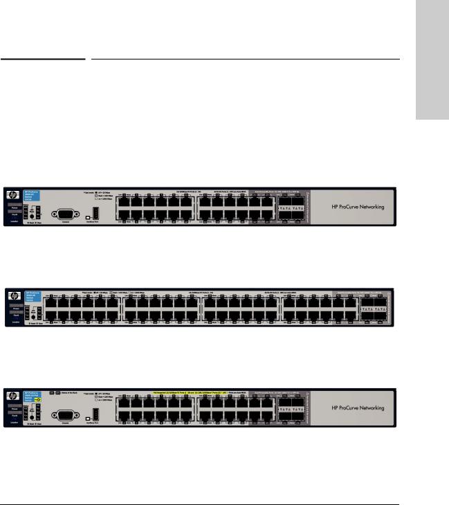
The HP ProCurve 3500, 3500yl and 6200yl switches are multiport switches that can be used to build high-performance switched networks. These switches are store-and-forward devices offering low latency for high-speed networking. The 3500 and 3500yl switches also support Redundant Power Supply and Power over Ethernet (PoE) technologies. The 6200yl switch supports Redundant Power Supply only.
HP ProCurve 3500-24 Switch (J9470A)
HP ProCurve 3500-48 Switch (J9472A)
HP ProCurve 3500-24-PoE Switch (J9471A)
Switch the Introducing
1-1

Introducing the Switch
Introducing the Switch
HP ProCurve 3500-48-PoE Switch (J9473A)
|
|
|
|
|
|
|
|
|
|
|
|
|
|
|
|
|
|
|
|
|
HP ProCurve 3500yl-24G-PWR Switch (J8692A) |
||||||||
|
ProCurve Switch |
Mdl |
EPS |
RPS |
Status of the Back |
*Spd mode: |
off = 10 Mbps |
|
|
|
|
|
PoE-Integrated 10/100/1000Base-T Ports (1 - 24T) — Ports are IEEE Auto MDI/MDI-X |
|
Dual-Personality Ports: 10/100/1000-T (T) or Mini-GBIC (M) |
Port |
|||||||||||||
|
Link |
1 |
|
3 |
5 |
7 |
9 |
11 |
Link |
13 Mode |
15 |
17 |
19 |
21T |
23T |
Link |
21M |
Mode |
23M |
||||||||||
|
3500yl-24G |
|
|
|
|
|
flash = 100 Mbps |
Mode |
each |
||||||||||||||||||||
|
J8692A |
PoE |
|
|
|
|
|
on = 1000 Mbps |
|
|
|
|
|
|
|
|
|
|
|
|
|
|
|
|
|
|
|
||
|
Status |
|
Act |
|
|
|
|
|
|
|
|
|
|
|
|
|
|
|
|
|
|
|
|
|
|
|
|
|
M) for |
Power |
PoE |
LED |
FDx |
|
|
|
|
|
|
|
|
|
|
|
|
|
|
|
|
|
|
|
|
|
|
|
|
|
(T or |
|
Tmp |
Mode |
Spd* |
|
|
|
|
|
|
|
|
|
|
|
|
|
|
|
|
|
|
|
|
|
|
|
|
|
one |
Fault |
Fan |
|
PoE |
|
|
|
|
|
|
|
|
|
|
|
|
|
|
|
|
|
|
|
|
|
|
|
|
|
only |
|
Test |
|
Usr |
|
|
|
|
|
|
|
|
|
|
|
|
|
|
|
|
|
|
|
|
|
|
|
|
|
Use |
Locator |
|
Reset |
Clear |
|
|
|
Console |
Auxiliary Port |
|
Link |
2 |
Mode |
4 |
6 |
8 |
10 |
12 |
Link |
14 Mode |
16 |
18 |
20 |
22T |
24T |
Link |
22M |
Mode |
24M |
|
|
|
|
|
|
! |
||||||||||||||||||||||||
|
|
|
|
|
|
|
|
|
|
|
|
|
|
|
|
|
|
|
|
|
|
HP ProCurve 3500yl-48G-PWR Switch (J8693A) |
||||||||||||||||
|
ProCurve Switch |
Mdl |
EPS |
RPS |
Status of the Back |
*Spd mode: |
off = 10 Mbps, |
flash = 100 Mbps, |
on = 1000 Mbps |
|
PoE-Integrated 10/100/1000Base-T Ports (1 - 48T) — Ports are IEEE Auto MDI/MDI-X |
|
|
|
|
|
|
41 |
|
Dual-Personality Ports: 10/100/1000-T (T) or Mini-GBIC (M) |
Port |
|||||||||||||||||
|
3500yl-48G |
Link |
1 |
Mode |
3 |
5 |
7 |
9 |
11 |
Link |
13 Mode |
15 |
17 |
19 |
21 |
23 |
Link |
25 Mode |
27 |
29 |
31 |
33 |
35 |
Link |
37 Mode |
39 |
43 |
45T |
47T |
Link |
45M |
Mode |
47M |
|||||
|
J8692A |
PoE |
|
|
|
|
|
|
|
|
|
|
|
|
|
|
|
|
|
|
|
|
|
|
|
|
|
|
|
|
|
|
|
|
|
|
each |
|
|
Status |
|
Act |
|
|
|
|
|
|
|
|
|
|
|
|
|
|
|
|
|
|
|
|
|
|
|
|
|
|
|
|
|
|
|
|
|
|
M) for |
Power |
PoE |
LED |
FDx |
|
|
|
|
|
|
|
|
|
|
|
|
|
|
|
|
|
|
|
|
|
|
|
|
|
|
|
|
|
|
|
|
|
|
(T or |
|
Tmp |
Mode |
Spd * |
|
|
|
|
|
|
|
|
|
|
|
|
|
|
|
|
|
|
|
|
|
|
|
|
|
|
|
|
|
|
|
|
|
|
one |
|
|
|
|
|
|
|
|
|
|
|
|
|
|
|
|
|
|
|
|
|
|
|
|
|
|
|
|
|
|
|
|
|
|
|
|
|||
Fault |
Fan |
|
PoE |
|
|
|
|
|
|
|
|
|
|
|
|
|
|
|
|
|
|
|
|
|
|
|
|
|
|
|
|
|
|
|
|
|
|
only |
|
Test |
|
Usr |
|
|
|
|
|
|
|
|
|
|
|
|
|
|
|
|
|
|
|
|
|
|
|
|
|
|
|
|
|
|
|
|
|
|
Use |
Locator |
|
Reset |
Clear |
Link |
2 |
Mode |
4 |
6 |
8 |
10 |
12 |
Link |
14 Mode |
16 |
18 |
20 |
22 |
24 |
Link |
26 Mode |
28 |
30 |
32 |
34 |
36 |
Link |
38 Mode |
40 |
42 |
44 |
46T |
48T |
Link |
46M |
Mode |
48M |
! |
|
|
|
|
||||||||||||||||||||||||||||||||||||
HP ProCurve 6200yl-24G mGBIC Switch (J8992A)
Power
Fault
Locator
The 3500yl-24G and 3500yl-48G switches have 20 and 44 auto-sensing 10/100/ 1000-T RJ-45 ports and 4 dual-personality ports—either auto-sensing 10/100/ 1000Base-T RJ-45 or mini-GBIC.
The 3500-24 and 3500-24-PoE switches have 20 auto-sensing 10/100Base-TX RJ-45 ports and 4 dual-personality ports—either auto-sensing 10/100/1000-T or SFP transceiver.
The 3500-48 and 3500-48-PoE switches have 44 auto-sensing 10/100Base-TX RJ-45 ports and 4 dual-personality ports—either auto-sensing 10/100/1000-T or SFP transceiver.
1-2
Introducing the Switch
In each of the 3500yl-24G and 3500yl-48G switches, one slot is provided in the back of the device to support a four port (two fixed CX4 ports and two X2 transceiver ports) 10 Gigabit per second Ethernet (10-GbE) module.
These products support optional network connectivity as shown in Table A-1 on page 1-3 .
Table A-1. Optional Network Connectivity, Speeds and Technologies
Transceiver Form-Factor and
Connector
Speed |
Technology |
Cabling1 |
SFP ("mini-GBIC") |
X2 |
|
|
|
Connector |
Connector |
|
|
|
|
|
100 Mbps |
100-FX |
Fiber (multimode) |
LC |
|
|
|
|
|
|
100-BX |
Fiber (single mode) |
LC |
|
|
|
|
|||
|
|
|
|
|
|
1000-T |
Copper (twisted-pair) |
RJ-452 |
|
|
1000-SX |
Fiber (multimode) |
LC |
|
|
|
|
|
|
1 Gbps |
1000-LX |
Fiber (multimode or single mode) |
LC |
|
|
|
|
|
|
|
1000-LH |
Fiber (single mode) |
LC |
|
|
|
|
|
|
|
1000-BX |
Fiber (single mode) |
LC |
|
|
|
|
|
|
|
10-Gig CX4 |
Copper (twinaxial) |
|
CX4 |
|
|
|
|
|
|
10-Gig SR |
Fiber (multimode) |
|
SC |
10 Gbps3 |
|
|
|
|
10-Gig LRM |
Fiber (multimode) |
|
SC |
|
|
10-Gig LR |
Fiber (single mode) |
|
SC |
|
|
|
|
|
|
10-Gig ER |
Fiber (single mode) |
|
SC |
|
|
|
|
|
1For supported transceivers, see www.procurve.com/faqs. Both ProCurve 10-GbE Transceivers and ProCurve Mini-GBICs and SFPs have links to a list of supported products (first question in the "General product information" category).
2The 1000Base-T mini-GBIC is supported on the 6200yl only.
3The 10Gbps transceivers are supported on the 3500yl and 6200yl switches only. They are not supported on the 3500 switches.
For technical details of cabling and technologies see "Cabling and Technology Information" in the appendices.
The 3500yl, 3500-24-PoE and 3500-48-PoE switches are designed to support Power over Ethernet (PoE) technology. The switches support 802.3af standard devices and some pre-standard PoE devices. For a list of these devices, see the FAQs for your switch model. This feature is the default and you must
Switch the Introducing
1-3

Introducing the Switch
Introducing the Switch
disable it if you do not want to use it. (Refer to the Management and Configuration Guide which is on the HP ProCurve Web site, www.procurve.com/manuals. (See page 5-1 for details.)
The dual-personality ports support either auto-sensing 10/100/1000Base-T RJ45, or SFP (mini-GBIC) transceivers. The SFP ports do not support PoE. If any of the SFP ports are used, the corresponding RJ-45 port will not be supplied with PoE power and will be disabled. For more information regarding the PoE capabilities of the 3500yl and 3500 PoE switches, see the HP ProCurve Power over Ethernet (PoE) Planning and Implementation Guide.
The 3500 and 3500yl switches can be connected to an HP ProCurve 620 Redundant and External Power Supply (RPS/EPS) and receive redundant power from that unit. If the internal power supply in the switch fails, the RPS/ EPS unit will immediately provide all the power necessary to keep the switch running. This includes power to run the switch and PoE power. If maximum PoE power is being used on all 48 ports, a 620 RPS/EPS is necessary to provide full power to the second 24 ports, and in this case, there is no redundancy.
The 6200yl switch can be connected to the HP ProCurve 620 Redundant and External Power Supply (RPS/EPS) and receive redundant power from that unit. If the internal power supply in the switch fails, the RPS/EPS unit will immediately provide the power necessary to keep the switch running. The 6200yl does not support PoE power.
The 6200yl, 3500yl and 3500 switches are designed to be used primarily as a high-density wiring closet or desktop switch. These switches can directly connect computers, printers and servers to provide dedicated bandwidth to those devices. By connecting the switch to hubs, other switches or routers, they can be used to build a switched network infrastructure. In addition, the 3500yl switches offer full network management capabilities.
This chapter describes the 3500yl, 6200yl and 3500 switches, including:
■Front and back of the switches
■Switch features
1-4
Introducing the Switch
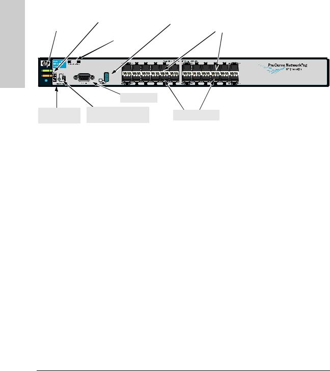
Front of the Switches
|
Front of the Switches |
|
Power, |
PoE, Temp, Fan, and |
|
Test Status LEDs |
||
Fault, and |
||
|
||
Locator |
Switch port LEDs |
|
LEDs |
|
|
|
|
|
|
|
|
|
|
|
|
|
|
|
Console port |
|
|
|
|
|
|
|
|
|
|
|
Dual-personality ports |
|||
|
|
10/100Base-TX RJ-45 ports |
|
||||||
|
|
|
|
|
|
|
|||
|
|
|
|
|
|
|
(10/100/1000-T or SFP) |
||
|
|
|
|
|
|
|
|
|
|
|
|
|
|
|
|
|
|
||
|
|
|
|
|
|
|
|
|
|
Reset and Clear |
|
Port LED Mode select |
|
|
|
||||
buttons |
|
button and indicator LEDs |
|
|
|
||||
|
|
|
|
|
|
|
|
|
|
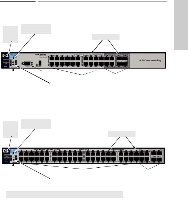
Figure 1-1. Front of the HP ProCurve 3500-24 Switch
Power, |
PoE, Temp, Fan, and |
|
Test Status LEDs |
||
Fault, and |
||
|
||
Locator |
Switch port LEDs |
|
LEDs |
Switch the Introducing
|
|
|
|
|
|
|
|
|
|
|
|
10/100Base-TX RJ-45 ports |
|
|
|
|
|
|
|
|
Dual-personality ports |
||
|
|
|
|
|
|
|
(10/100/1000-T or SFP) |
Reset and Clear |
|
Port LED Mode select |
|
|
|
||
buttons |
|
button and indicator LEDs |
|
|
|
||
|
|
|
|
|
|
|
|
On the 3500-48 switch, the Console and Auxiliary ports are located on the back of the unit.
Figure 1-2. Front of the HP ProCurve 3500-48 Switch
1-5
Introducing the Switch
Introducing the Switch
Front of the Switches
Power, |
PoE, Temp, Fan, and |
|
Test Status LEDs |
||
Fault, and |
||
|
||
Locator |
Switch port LEDs |
|
LEDs |
||
|
|
|
|
|
|
|
|
|
|
|
|
|
|
|
Console port |
|
|
|
|
|
|
|
|
|
|
PoE-Integrated 10/100Base-TX RJ-45 |
|
|
||
|
|
|
|
|
|
Dual-personality ports |
|||
|
|
|
|
|
|
|
ports* |
|
(10/100/1000-T or SFP) |
|
|
|
|
|
|||||
|
|
|
|
|
|
|
|
||
|
|
|
Port LED Mode select |
|
|
|
|||
Reset and Clear |
|
|
|
|
|||||
buttons |
|
button and indicator LEDs |
|
|
|
||||
|
|
|
|
|
|
|
|
|
|
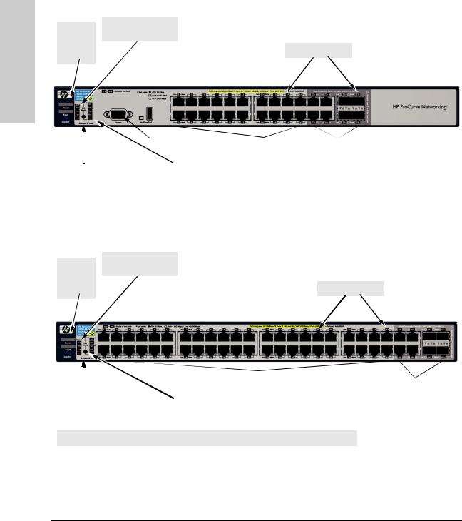
Figure 1-3. Front of the HP ProCurve 3500-24-PoE Switch
Power, |
PoE, Temp, Fan, and |
|
Test Status LEDs |
||
Fault, and |
||
|
||
Locator |
Switch port LEDs |
|
LEDs |
|
|
|
|
|
|
|
|
|
|
|
|
PoE-Integrated 10/100Base-TX RJ-45 |
|
|
|
|
|
|
Dual-personality ports |
||||
|
|
|
|
|
ports* |
|
|
|
|
|
|
|
|
|
(10/100/1000-T or SFP) |
|
|
|
|
|
|
|
|
Reset and Clear |
|
Port LED Mode select |
|
|
|
||
buttons |
|
button and indicator LEDs |
|
|
|
||
|
|
|
|
|
|
|
|
On the 3500-48-PoE switch, the Console and Auxiliary ports are located on the back of the unit.
Figure 1-4. Front of the HP ProCurve 3500-48-PoE Switch
1-6
Introducing the Switch
Front of the Switches
Power, |
PoE, Temp, Fan, and |
|
|
Fault, and |
Test Status LEDs |
|
|
Locator |
Auxiliary port |
Switch port LEDs |
|
and LED* |
|||
LEDs |
|||
Module, EPS, and |
|
||
|
|
||
|
RPS, Status LEDs |
|
|
ProCurve Switch |
Mdl |
EPS |
RPS |
Status of the Back |
*Spd mode: |
off = 10 Mbps |
|
|
|
|
|
PoE-Integrated 10/100/1000Base-T Ports (1 - 24T) — Ports are IEEE Auto MDI/MDI-X |
|
Dual-Personality Ports: 10/100/1000-T (T) or Mini-GBIC (M) |
Port |
|||||||||||||
|
Link |
1 |
|
3 |
5 |
7 |
9 |
11 |
Link |
13 Mode |
15 |
17 |
19 |
21T |
23T |
Link |
21M |
Mode |
23M |
||||||||||
|
3500yl-24G |
|
|
|
|
|
flash = 100 Mbps |
Mode |
each |
||||||||||||||||||||
|
J8692A |
PoE |
|
|
|
|
|
on = 1000 Mbps |
|
|
|
|
|
|
|
|
|
|
|
|
|
|
|
|
|
|
|
||
|
Status |
|
Act |
|
|
|
|
|
|
|
|
|
|
|
|
|
|
|
|
|
|
|
|
|
|
|
|
|
M) for |
Power |
PoE |
LED |
FDx |
|
|
|
|
|
|
|
|
|
|
|
|
|
|
|
|
|
|
|
|
|
|
|
|
|
(T or |
|
Tmp |
Mode |
Spd* |
|
|
|
|
|
|
|
|
|
|
|
|
|
|
|
|
|
|
|
|
|
|
|
|
|
one |
Fault |
Fan |
|
PoE |
|
|
|
|
|
|
|
|
|
|
|
|
|
|
|
|
|
|
|
|
|
|
|
|
|
only |
|
Test |
|
Usr |
|
|
|
|
|
|
|
|
|
|
|
|
|
|
|
|
|
|
|
|
|
|
|
|
|
Use |
Locator |
|
Reset |
Clear |
|
|
|
Console |
Auxiliary Port |
|
Link |
2 |
Mode |
4 |
6 |
8 |
10 |
12 |
Link |
14 Mode |
16 |
18 |
20 |
22T |
24T |
Link |
22M |
Mode |
24M |
! |
|
|
Console port* |
|
Dual-personality ports |
|
Reset and Clear |
10/100/1000Base-T RJ-45 |
||||
|
|||||
|
(1000Base-T* or mini-GBIC) |
||||
buttons |
|
||||
|
|
||||
|
|
|
|||
Port LED Mode select button and indicator LEDs
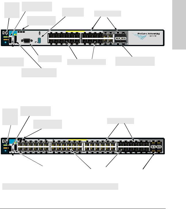
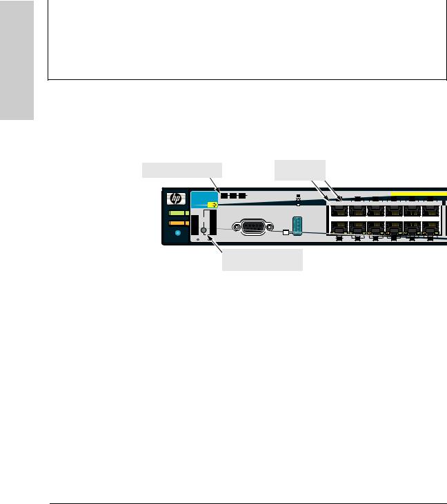
Figure 1-5. Front of the HP ProCurve 3500yl-24G Switch
Power, |
PoE, Temp, Fan, and |
|
Test Status LEDs |
|
|
Fault, and |
|
|
|
|
|
Locator |
|
Switch port LEDs |
LEDs |
Module, EPS, and |
|
|
RPS, Status LEDs |
|
|
ProCurve Switch |
Mdl |
EPS |
RPS |
Status of the Back |
*Spd mode: |
off = 10 Mbps, |
flash = 100 Mbps, |
on = 1000 Mbps |
|
PoE-Integrated 10/100/1000Base-T Ports (1 - 48T) — Ports are IEEE Auto MDI/MDI-X |
|
|
|
|
|
|
41 |
|
Dual-Personality Ports: 10/100/1000-T (T) or Mini-GBIC (M) |
Port |
|||||||||||||||||
|
3500yl-48G |
Link |
1 |
Mode |
3 |
5 |
7 |
9 |
11 |
Link |
13 Mode |
15 |
17 |
19 |
21 |
23 |
Link |
25 Mode |
27 |
29 |
31 |
33 |
35 |
Link |
37 Mode |
39 |
43 |
45T |
47T |
Link |
45M |
Mode |
47M |
|||||
|
J8692A |
PoE |
|
|
|
|
|
|
|
|
|
|
|
|
|
|
|
|
|
|
|
|
|
|
|
|
|
|
|
|
|
|
|
|
|
|
each |
|
|
Status |
|
Act |
|
|
|
|
|
|
|
|
|
|
|
|
|
|
|
|
|
|
|
|
|
|
|
|
|
|
|
|
|
|
|
|
|
|
M) for |
Power |
PoE |
LED |
FDx |
|
|
|
|
|
|
|
|
|
|
|
|
|
|
|
|
|
|
|
|
|
|
|
|
|
|
|
|
|
|
|
|
|
|
(T or |
|
Tmp |
Mode |
Spd * |
|
|
|
|
|
|
|
|
|
|
|
|
|
|
|
|
|
|
|
|
|
|
|
|
|
|
|
|
|
|
|
|
|
|
one |
|
|
|
|
|
|
|
|
|
|
|
|
|
|
|
|
|
|
|
|
|
|
|
|
|
|
|
|
|
|
|
|
|
|
|
|
|||
Fault |
Fan |
|
PoE |
|
|
|
|
|
|
|
|
|
|
|
|
|
|
|
|
|
|
|
|
|
|
|
|
|
|
|
|
|
|
|
|
|
|
only |
|
Test |
|
Usr |
|
|
|
|
|
|
|
|
|
|
|
|
|
|
|
|
|
|
|
|
|
|
|
|
|
|
|
|
|
|
|
|
|
|
Use |
|
|
|
|
|
|
|
|
|
|
|
|
|
|
|
|
|
|
|
|
|
|
|
|
|
|
|
|
|
|
|
|
|
|
|
|
|
|
|
Locator |
|
Reset |
Clear |
Link |
2 |
Mode |
4 |
6 |
8 |
10 |
12 |
Link |
14 Mode |
16 |
18 |
20 |
22 |
24 |
Link |
26 Mode |
28 |
30 |
32 |
34 |
36 |
Link |
38 Mode |
40 |
42 |
44 |
46T |
48T |
Link |
46M |
Mode |
48M |
! |
|
|
|
|
||||||||||||||||||||||||||||||||||||
|
|
|
|
|
|
|
|
Reset and Clear |
|
Port LED Mode select |
|
|
|
|
|
|
|
10/100/1000Base-T RJ-45 ports* |
|
|
|||
buttons |
|
button and indicator LEDs |
|
|
|
Dual-personality ports |
|
|
|||||||
|
|
|
|
|
|
|
(1000Base-T* or mini-GBIC) |
|
|
|
|
|
|
|
|
On the 3500yl-48G switch, the Console and Auxiliary ports are located on the back of the unit.
Figure 1-6. Front of the HP ProCurve 3500yl-48G Switch
Switch the Introducing
1-7
Introducing the Switch
Introducing the Switch
Front of the Switches
Power, |
|
|
|
|
|
Temp, Fan, and Test |
|
|
|
|
|
|
|
|
|
|
|
|
|
|
Auxiliary port |
|
|
|
|
|
|
|
|
|
|||||||||||||||||||||||||
Fault, and |
|
|
|
|
|
Status LEDs |
|
|
|
|
|
|
|
|
|
|
|
|
|
|
|
|
and LED |
|
|
|
|
|
|
|
|
|
|||||||||||||||||||||||
locator |
|
|
|
|
|
|
|
|
|
|
|
|
|
|
|
|
|
|
|
|
|
|
|
|
|
|
|
|
|
|
|
|
|
|
|
|
|
|
|
|
|
Switch port LEDs |
|
||||||||||||
LEDs |
|
|
|
|
|
|
|
|
|
|
|
|
|
|
|
|
|
|
|
|
|
|
|
|
|
|
|
|
|
|
|
|
|
|
|
|
|
|
|
|
|
|
|||||||||||||
|
|
|
|
|
|
Module and RPS |
|
|
|
|
|
|
|
|
|
|
|
|
|
|
|
|
|
|
|
|
|
|
|
|
|
|
|
|
|
|
|
|
|
|
|
|
|
|
|
|
|
|
|||||||
|
|
|
|
|
|
|
|
|
|
|
|
|
|
|
|
|
|
|
|
|
|
|
|
|
|
|
|
|
|
|
|
|
|
|
|
|
|
|
|
|
|
|
|
|
|
|
|
||||||||
|
|
|
|
|
|
|
Status LEDs |
|
|
|
|
|
|
|
|
|
|
|
|
|
|
|
|
|
|
|
|
|
|
|
|
|
|
|
|
|
|
|
|
|
|
|
|
|
|
|
|
|
|
||||||
|
|
|
|
|
|
|
|
|
|
|
|
|
|
|
|
|
|
|
|
|
|
|
|
|
|
|
|
|
|
|
|
|
|
|
|
|
|
|
|
|
|
|
|
|
|
|
|
|
|
|
|
|
|
|
|
|
|
|
|
|
|
|
|
|
|
|
|
|
|
|
|
|
|
|
|
|
|
|
|
|
|
|
|
|
|
|
|
|
|
|
|
|
|
|
|
|
|
|
|
|
|
|
|
|
|
|
|
|
|
|
|
|
|
|
|
|
|
|
|
|
|
|
|
|
|
|
|
|
|
|
|
|
|
|
|
|
|
|
|
|
|
|
|
|
|
|
|
|
|
|
|
|
|
|
|
|
|
|
|
|
|
|
|
|
|
|
|
|
|
|
|
|
|
|
|
|
|
|
|
|
|
|
|
|
|
|
|
|
|
|
|
|
|
|
|
|
|
|
|
|
|
|
|
|
|
|
|
|
|
|
|
|
|
|
|
|
|
|
|
|
|
|
|
|
|
|
|
|
|
|
|
|
|
|
|
|
|
|
|
|
|
|
|
|
|
|
|
|
|
|
|
|
|
|
|
|
|
|
|
|
|
|
|
|
|
|
|
|
|
|
|
|
|
|
|
|
|
|
|
Power
Fault
Locator
Reset and Clear
buttons
 Console port
Port LED Mode select
Mini-GBIC ports
button and indicator LEDs
Figure 1-7. Front of the HP ProCurve 6200yl-24G Switch
Network Ports
■All RJ-45 ports provide “HP Auto MDIX” features, which means you can use either straight-through or crossover twisted-pair cables to connect any network devices to the switch.
■The 3500 and 3500yl switches provide four, dual-personality ports that support either the 10/100/1000Base-T RJ-45 connector or an HP ProCurve SFP (mini-GBIC) for fiber-optic connections.
The RJ-45 connectors support the IEEE Auto MDI/MDI-X feature, which means you can use either straight-through or crossover twisted-pair cables to connect any network device to the switch.
Dual-Personality Port Operation. By default, the RJ-45 connectors are enabled. If a mini-GBIC is installed in a slot, it is enabled and the associated RJ-45 connector is disabled and cannot be used. If the mini-GBIC is removed, the associated RJ-45 port is automatically re-enabled.
The RJ-45 connector also supplies PoE power until a mini-GBIC is installed. The PoE power is turned off when a mini-GBIC is plugged in.
1-8

Introducing the Switch |
|
|
Front of the Switches |
|
|
■ Each of the 3500yl and 6200yl switches have one, 10 gigabit expansion slot |
|
|
|
||
that can accept a 4 x 10 gigabit transceiver module. The modules provide |
Introducing |
|
either copper or fiber optic media that conforms to the 10-Gigabit |
||
|
||
Ethernet standard as well as dual 10 gigabit copper or uplink ports. |
|
|
Only the 3500yl and 6200yl switches support a yl module. The yl module |
|
|
provides four ports: |
the |
|
• two 10-GbE CX4 fixed copper ports |
||
Switch |
||
• two 10-GbE flexible media slots that support different transceivers. |
||
|
||
See the HP ProCurve Switch yl Module Installation Guide for more |
|
|
information on supported transceivers. The 3500 switches do not |
|
|
support a module slot. |
|
1-9

Introducing the Switch
Introducing the Switch
Front of the Switches
|
LEDs |
|
|
Table 1-2. Switch LEDs |
|
|
|
|
Switch |
State |
Meaning |
LEDs |
|
|
|
|
|
Power |
On |
The switch is receiving power. |
(green) |
Off |
The switch is NOT receiving power. |
|
|
|
Fault |
Off |
The normal state; indicates there are no fault conditions on the switch. |
(orange) |
blink |
A fault has occurred on the switch, one of the switch ports, module in the rear of the |
|
||
|
orange* |
switch, or the fan. The Status LED for the component with the fault will blink |
|
|
simultaneously. |
|
On |
On briefly after the switch is powered on or reset, at the beginning of switch self test. |
|
|
If this LED is on for a prolonged time, the switch has encountered a fatal hardware |
|
|
failure, or has failed its self test. See chapter 4, “Troubleshooting” for more information. |
|
|
|
Locator |
|
Reserved for future development |
(Blue) |
|
|
|
|
|
Test |
Off |
The normal operational state; the switch is not undergoing self test. |
(green) |
On |
The switch self test and initialization are in progress after the switch has been power |
|
||
|
|
cycled or reset. The switch is not operational until this LED goes off. The Self Test LED |
|
|
also comes on briefly when you “hot swap” a mini-GBIC into the switch; the mini-GBIC |
|
|
is self tested when it is hot swapped. |
|
blink green* |
A component of the switch has failed its self test. The status LED for that component, |
|
|
for example an RJ-45 port, and the switch Fault LED will blink simultaneously. |
|
|
|
Port LEDs |
Link |
Indicates the port LEDs are displaying link information: |
(green – |
|
• if the port LED is on, the port is enabled and receiving a link indication from the |
Link and |
|
connected device. |
Mode) |
|
• if the port LED is off, the port has no active network cable connected, or is not |
|
|
receiving link beat or sufficient light. Otherwise, the port may have been disabled |
|
|
through the switch console, the web browser interface, or ProCurve Manager. |
|
|
if the port LED is blinking* (orange) simultaneously with the Fault LED, the |
|
|
corresponding port has failed its self test. |
|
Mode |
The operation of the Mode LED is controlled by the LED Mode select button, and the |
|
|
current setting is indicated by the LED Mode indicator LEDs near the button. Press the |
|
|
button to step from one view mode to the next. The default view is Activity (Act). |
|
|
|
LED Mode |
Act |
Indicates the port LEDs are displaying network activity information. |
View |
|
|
(green) |
|
|
|
FDx |
Indicates port LEDs are lit for ports in Full Duplex Mode. Off indicates ½ duplex. |
|
|
|
1-10

|
|
|
Introducing the Switch |
|
|
|
|
|
Front of the Switches |
|
|
|
|
|
|
|
|
|
Switch |
State |
Meaning |
|
|
|
LEDs |
|
|
|
Introducing |
|
|
|
|
|
|
|
|
Spd |
Indicates the port LEDs are displaying the connection speed at which each port is |
|
|
|
|
|
operating: |
|
|
|
|
|
• if the port LED is off, the port is operating at 10 Mbps. |
|
|
|
|
|
• if the port LED is blinking**, the port is operating at 100 Mbps. |
|
the |
|
|
|
• if the port LED is on continuously, the port is operating at 1000 Mbps. |
|
|
|
|
|
|
Switch |
|
|
|
PoE |
• If the Mode LED is on the port is providing PoE power. |
|
|
|
|
|
|
||
|
|
|
• If the Mode LED is off the port is not providing PoE power. |
|
|
|
|
|
• If the Link LED is on the port is enabled for PoE. |
|
|
|
|
|
• If the Link LED is off the port is disabled for PoE. |
|
|
|
|
|
• If the Link LED is blinking, the port has an error or the port is denied power due to |
|
|
|
|
|
insufficient power. |
|
|
|
|
Usr |
Reserved for future development |
|
|
|
|
|
|
|
|
|
Mdl |
On |
Expansion module is plugged into expansion slot and operating correctly |
|
|
|
(Module |
Blink orange |
Expansion module is plugged into expansion slot but has experienced a fault |
|
|
|
Status, |
Off |
Expansion module is not plugged into expansion slot |
|
|
|
green/ |
|
|
|
|
|
orange) (This |
|
|
|
|
|
is not |
|
|
|
|
|
applicable to |
|
|
|
|
|
the 3500 |
|
|
|
|
|
switches.) |
|
|
|
|
|
|
|
|
|
|
|
RPS Status |
On |
Normal operation. RPS is connected and operating correctly. RPS could be powering |
|
|
|
(green/ |
|
the unit. |
|
|
|
orange) |
Blink orange |
RPS is connected but has experienced a fault. |
|
|
|
|
Off |
RPS is not connected or is not powered on. |
|
|
|
|
|
|
|
|
|
EPS Status |
On |
Connected to an External Power Supply, and receiving power. |
|
|
|
(green/ |
Blink orange |
The External Power Supply is connected but has experienced a fault or is unplugged. |
|
|
|
orange) |
Off |
The switch is not connected to an EPS. (EPS is not applicable to the 3500-24 non-PoE |
|
|
|
|
|
or 3500-48 non-PoE switches.) |
|
|
|
|
|
|
|
|
|
Fan Status |
On |
Normal operation, all fans are ok. |
|
|
|
(green/ |
Blink |
One of the unit’s fans has failed. The switch Fault LED will be blinking simultaneously. |
|
|
|
orange) |
orange* |
|
|
|
|
|
|
|
|
|
|
PoE Status |
On |
When the switch is ready to start supplying PoE power. |
|
|
|
(green/ |
Off |
Should be off only during the boot process. |
|
|
|
Orange) |
Blink |
If any port has a internal hardware failure |
|
|
|
|
orange* |
|
|
|
|
|
Blink |
If any port is denied PoE power or detecting an external PD fault |
|
|
|
|
orange** |
|
|
|
|
|
|
|
|
|
|
Temp |
On |
Switch temperature is normal. |
|
|
|
(green/ |
Blink |
An over temperature condition has been detected. |
|
|
|
Orange) |
|
|
||
|
|
orange** |
|
|
|
|
|
|
|
|
|
|
|
|
|
|
|
1-11
Introducing the Switch
Introducing the Switch
Front of the Switches
Switch |
State |
Meaning |
LEDs |
|
|
|
|
|
Auxiliary |
|
Reserved for future development |
(green) |
|
|
|
|
|
* The blinking behavior is an on/off cycle once every 1.6 seconds, approximately. ** The blinking behavior is an on/off cycle once every 0.5 seconds, approximately.
LED Mode Select Button and Indicator LEDs
The operation of the Mode LED is controlled by the LED Mode select button, and the current setting is indicated by the LED Mode indicator LEDs near the button. Press the button to step from one view mode to the next.
Expansion Module LED |
Port LEDs Link |
|
|
|
|
|
|
|||
and Mode |
|
|
|
|
|
|
||||
|
|
|
|
|
|
|
|
|
||
ProCurve Switch Mdl EPS RPS Status of the Back |
*Spd mode: off = 10 Mbps |
|
|
|
PoE-Integrated 10/100/1000Base-T Ports (1 |
|||||
1 Mode |
3 |
5 |
7 |
9 |
11 |
|||||
3500yl-24G |
flash = 100 Mbps Link |
|||||||||
J8692A |
PoE |
on = 1000 Mbps |
|
|
|
|
|
|
||
Status |
|
Act |
|
|
|
|
|
|
|
|
Power PoE |
LED |
FDx |
|
|
|
|
|
|
|
|
Tmp |
Mode |
Spd* |
|
|
|
|
|
|
|
|
Fault |
Fan |
PoE |
|
Test |
Usr |
Locator |
Reset |
Clear |
Console |
Auxiliary Port |
Link 2 Mode |
4 |
6 |
8 |
10 |
12 |
LED Mode select button  and indicator LEDs
Figure 1-8. Indicator LEDs on the HP ProCurve 3500yl-24G Switch
1-12
Introducing the Switch
Front of the Switches
|
|
Port LEDs Link |
Expansion Module LEDs |
|
|
|
|
and Mode |
|
|
|
ProCurve Switch |
Mdl |
EPS |
RPS |
Status of the Back |
*Spd mode: |
off = 10 Mbps, |
flash = 100 Mbps, |
on = 1000 Mbps |
|
PoE-Integrated 10/100/1000Base-T P |
||||||||
|
3500yl-48G |
Link |
1 |
Mode |
3 |
5 |
7 |
9 |
11 |
Link |
13 Mode |
15 |
17 |
19 |
21 |
23 |
|||
|
J8692A |
PoE |
|
|
|
|
|
|
|
|
|
|
|
|
|
|
|
|
|
|
Status |
|
Act |
|
|
|
|
|
|
|
|
|
|
|
|
|
|
|
|
|
|
|
|
|
|
|
|
|
|
|
|
|
|
|
|
|
|
|
|
Power |
PoE |
LED |
FDx |
|
|
|
|
|
|
|
|
|
|
|
|
|
|
|
|
|
Tmp |
Mode |
Spd * |
|
|
|
|
|
|
|
|
|
|
|
|
|
|
|
|
|
|
|
|
|
|
|
|
|
|
|
|
|
|
|
|
|
|
||
Fault |
Fan |
|
PoE |
|
|
|
|
|
|
|
|
|
|
|
|
|
|
|
|
|
Test |
|
Usr |
|
|
|
|
|
|
|
|
|
|
|
|
|
|
|
|
Locator |
|
Reset |
Clear |
Link |
2 |
Mode |
4 |
6 |
8 |
10 |
12 |
Link |
14 Mode |
16 |
18 |
20 |
22 |
24 |
|
|
|
|
|
|
|
|
|
|
|
|
|
|
|
|
|
|
|
||
LED Mode select button and indicator LEDs
Figure 1-9. Indicator LEDs on the HP ProCurve 3500yl-48G Switch
Expansion Module LEDs
Power
Fault
Locator
|
|
|
|
|
|
|
|
|
|
|
LED Mode select button |
|
Port LEDs Link |
|
|
|
|
and indicator LEDs |
|
and Mode |
|
|
|
|
|
|
|
Figure 1-10. Indicator LEDs on the HP ProCurve 6200yl-24G Switch
■Each port has a Link LED. If it is lit, the port has a link. If the Link LED is blinking, the port has failed its self test. The Fault and Self Test LEDs will be blinking simultaneously.
■If the Activity (Act) indicator LED is lit, each port LED displays activity information for the associated port—it flickers as network traffic is received and transmitted through the port.
■If the Full Duplex (FDx) indicator LED is lit, the port LEDs light for those ports that are operating in full duplex.
■If the Speed (Spd) indicator LED is lit, the port LEDs behave as follows to indicate the connection speed for the port:
•Off = 10 Mbps
•blinking = 100 Mbps (the blinking behavior is a repeated on/off cycle once every 0.5 sec.)
•On = 1000 Mbps
■The Usr Mode LED is reserved for future development.
Switch the Introducing
1-13

Introducing the Switch
Introducing the Switch
Front of the Switches
■If the PoE indicator LED is lit, the Link and Mode LEDs indicate PoE status.
Link LED:
•On = PoE is enabled on this port.
•Off = PoE is disabled on this port.
•Slow Blinking = Internal PoE fault on this port. or has been denied power.
•Fast Blinking = This port is denied PoE power or has an external load fault.
Mode LED:
•On = PoE power is be supplied on this port.
•Off = PoE is not being supplied on this port.
Reset Button
This button is used to reset the switch while it is powered on. This action clears any temporary error conditions that may have occurred and executes the switch self test. It is also used when restoring the switch factory default configuration. See the Clear Button section, Restoring Factory Default Configuration.
Clear Button
This button is used for these purposes:
■Deleting Passwords - When pressed by itself for at least one second, the button deletes any switch console access passwords that you may have configured. Use this feature if you have misplaced the password and need console access.
This button is provided for your convenience, but its presence means that if you are concerned with the security of the switch configuration and operation, you should make sure the switch is installed in a secure location, such as a locked wiring closet.
■Restoring Factory Default Configuration - When pressed with the Reset button in a specific pattern, any configuration changes you may have made through the switch console, the web browser interface, and SNMP management are removed, and the factory default configuration is restored to the switch. For the specific method to restore the factory default configuration, see “Restoring the Factory Default Configuration” on page 11, in chapter 4, “Troubleshooting” of this manual.
1-14

Introducing the Switch
Front of the Switches
Expansion Module LEDs
“Expansion Module” LEDs refer to the LEDs specific to the expansion module. These LEDs are located on the physical expansion module bulkhead. These LEDs are only viewable in the rear of the 3500yl-48G product on the expansion slot module itself. These LEDs are duplicated on the front panel of the 3500yl24G and 6200yl-24G switches. The 3500-24/48 PoE and 3500-24/48 non-PoE switches do not have an Expansion Module LED.
|
|
Table 1-3. |
Expansion Module LEDs |
||
|
|
|
|
|
|
Name |
Color |
|
Mode |
|
Description |
|
|
|
|
|
|
Expansion Module LEDs per module |
|
|
|||
|
|
|
|
|
|
Module |
Green |
|
On |
|
Expansion module is plugged into expansion slot and operating correctly |
(Mdl) Power |
|
|
|
|
|
|
|
|
Off |
|
Expansion module's power has been turned OFF, and the card can be |
|
|
|
|
|
removed from the box if necessary. |
Module |
Orange |
|
On |
|
Expansion module is plugged into expansion slot but has experienced a |
(Mdl) Fault |
|
|
|
|
fault |
|
|
|
|
|
|
Expansion Module LEDs per port |
|
|
|||
|
|
|
|
|
|
Link |
Green |
|
On |
|
Indicates that the port LEDs are displaying link information: |
|
|
|
|
|
• if the port LED is on, the port is enabled and receiving a link indication |
|
|
|
|
|
from the connected device. |
|
|
|
Off |
|
• if the port LED is off, the port has no active network cable connected, |
|
|
|
|
|
or is not receiving link beat or sufficient light. Otherwise, the port may |
|
|
|
|
|
have been disabled through the switch console, the web browser |
|
|
|
blinking |
|
interface, or ProCurve Manager. |
|
|
|
|
• if the port LED is blinking* simultaneously with the Fault LED, the |
|
|
|
|
|
|
corresponding port has failed its self test. |
|
|
|
|
|
|
Act |
Green |
|
On |
|
Indicates the port LEDs are displaying network activity information. |
|
|
|
|
|
|
Expansion module LEDs operate in modes for Link and Activity. FDx and Spd modes have no meaning for the 10-GbE ports on the expansion module.
C a u t i o n |
It is required the switch be powered down before inserting or extracting the |
|
Expansion Module. |
|
|
Switch the Introducing
1-15
Introducing the Switch
Introducing the Switch
Back of the Switch
Back of the Switch
RPS Input Port
AC power connector
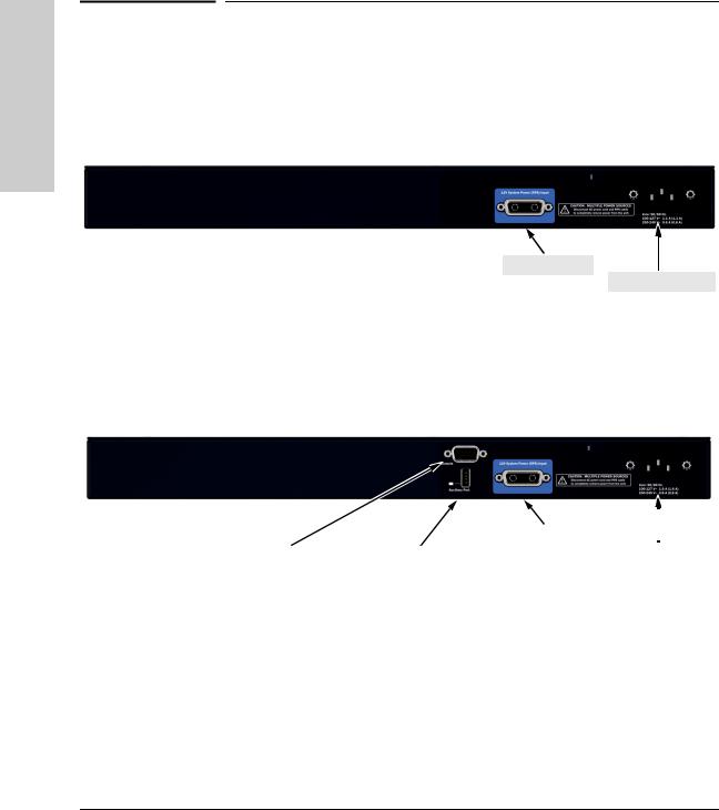
Figure 1-11. Back of the HP ProCurve 3500-24 Switch
|
|
|
|
|
|
|
|
|
|
|
|
|
RPS Input Port |
|
|
|
|
|
|
|
|
|||||
|
|
|
|
|
|
AC power connector |
||
Console Port |
|
Auxiliary Port and LED |
|
|
|
|||
|
|
|
|
|
|
|
|
|
|
|
|
|
|
|
|
|
|
Figure 1-12. Back of the HP ProCurve 3500-48 Switch
1-16
Introducing the Switch
Back of the Switch
EPS Input Port
RPS Input Port
AC power connector
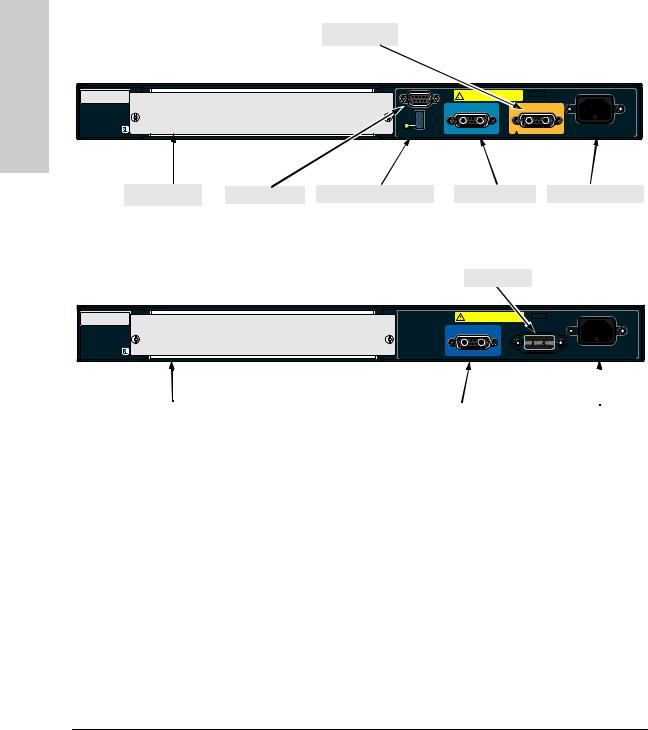
Figure 1-13. Back of the HP ProCurve 3500-24-PoE Switch
EPS Input Port
|
|
|
|
|
|
|
|
|
|
|
|
RPS Input Port |
|
|
|
|
|
|
|
|
|
|
|
Console Port |
|
Auxiliary Port and LED |
|
|
|
AC power connector |
|
|
|
|
|
|
|
|
|
|
|
|
|
|
|
|
|
Figure 1-14. Back of the HP ProCurve 3500-48-PoE Switch
EPS Input Port
Serial No. SG12345678
System MAC 0001e7
Address 123456
CAUTION: MULTIPLE POWER SOURCES Disconnect all AC power cords, and EPS and RPS cables to completely remove power from the unit.
12V System Power (RPS) Input |
PoE |
50V PoE (EPS) Input |
 Connect ProCurve 620 EPS only
Line: 50/60 Hz. 100-127 V~ 10 A 200-240 V~ 5 A
|
|
|
|
|
|
|
|
|
RPS Input Port |
|
AC power connector |
||
yl module slot |
||||||
|
|
|
|
|
||
|
|
|
|
|
|
|
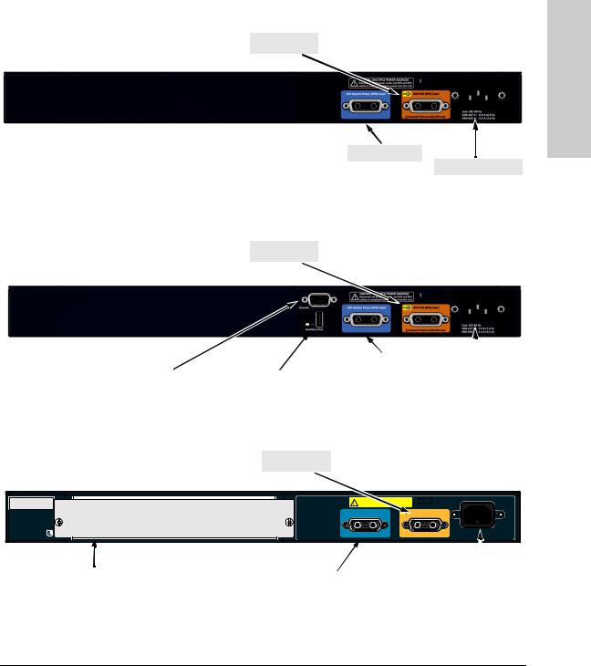
Figure 1-15. Back of the HP ProCurve 3500yl-24G Switch
Switch the Introducing
1-17
Introducing the Switch
Introducing the Switch
Back of the Switch
.
EPS Input Port
Serial No. |
SG12345678 |
CAUTION: MULTIPLE POWER SOURCES |
|
|
System MAC |
0001e7 |
Disconnect all AC power cords, and EPS and RPS |
|
|
cables to completely remove power from the unit. |
|
|||
Address |
123456 |
|
||
|
|
|
||
|
Console |
12V System Power (RPS) Input |
PoE |
50V PoE (EPS) Input |
Line: 50/60 Hz.
Auxiliary Port Connect ProCurve 620 EPS only 100-127 V~ 10 A 200-240 V~ 5 A
yl module slot Console Port Auxiliary Port and LED RPS Input Port AC power connector
|
|
Figure 1-16. Back of the HP ProCurve 3500yl-48G Switch |
|
|
|
. |
|
|
|
Do Not Use |
|
Serial No. |
SG12345678 |
CAUTION: MULTIPLE POWER SOURCES |
|
System MAC |
0001e7 |
Disconnect all AC power cords, and EPS and RPS |
|
cables to completely remove power from the unit. |
|||
Address |
123456 |
||
|
12V System Power (RPS) Input
Line: 50/60 Hz. 100-127 V~ 10 A 200-240 V~ 5 A
|
|
|
|
|
|
yl module slot |
|
RPS Input Port |
|
|
|
|
|
AC power connector |
|||
|
|
|
|
|
|
Figure 1-17. Back of the HP ProCurve 6200yl-24G Switch
yl Module Slot
Only the 3500yl and 6200yl switches support a yl module. The yl module provides 4 ports:
■two 10-GbE CX4 fixed copper ports
■two 10-GbE flexible media slots that support a number of different transceivers. See the HP ProCurve Switch yl Module Installation Guide for more information on supported transceivers.
The 3500 switches do not support a module slot.
1-18

Introducing the Switch
Back of the Switch
RPS and EPS Input Port
The 3500, 3500yl and 6200yl switches support connectivity to a redundant power supply. The “ProCurve 620 Redundant and External Power Supply (RPS/EPS) is an accessory product for these Switches. The RPS/EPS provides redundant and additional PoE power to the switch products to back up the power supply in the switch in case of loss of AC or PoE power. Or, if maximum PoE power is being used on all 48 ports, a 620 RPS/EPS will be necessary to provide full power to the second 24 ports, and in this case, there would be no redundancy.
Console Port
This port is used to connect a console to the switch by using the serial cable supplied with the switch. This connection is described under “10. Connect a Console to the Switch (Optional)” on page 20 in chapter 2, “Installing the Switch.” The console can be a PC or workstation running a VT-100 terminal emulator, or a VT-100 terminal. The console port is located on the front of the 3500-24, 3500yl-24G and 6200yl-24G switches, and on the back of the 3500-48 and 3500yl-48G switches.
Power Connector
The 3500, 3500yl and 6200yl switches do not have a power switch; they are powered on when connected to an active AC power source. These switches automatically adjust to any voltage between 100--240 volts and either 50 or 60 Hz. There are no voltage range settings required.
Switch the Introducing
1-19

Introducing the Switch
Introducing the Switch
Switch Features
Switch Features
The features of the 3500, 3500yl and 6200yl Switches include:
■The 3500yl have 24 or 48 auto-sensing 10/100/1000Base-T RJ-45 ports. The 3500 have 20 or 44 auto-sensing 10/100Base-T RJ-45 ports.
■Four dual-personality ports—either the auto sensing 10/100/1000Base-T RJ-45 or the SFP (mini-GBIC) transceivers can be used for each port.
■The 6200yl provides 24 mini-GBIC ports.
■One module slot is provided in the back of the yl switches to support a series of transceivers to provide connectivity to other switch boxes, to a 10 Gig concentrator or to any Ethernet compatible uplink.
■The auxiliary port is reserved for future development.
■The switches can be connected to an HP ProCurve RPS/EPS and receive redundant power from that unit. If the internal power supply in the switch fails, the RPS/EPS unit will immediately provide all the power necessary to keep the switch running.
■Power over Ethernet (PoE) operation—the 3500-24-PoE, 3500-48-PoE and 3500yl switches are IEEE 802.af compliant and provide up to 15.4 W per port to power IP phones, wireless access points, web cameras, and more. For more information, see the PoE Planning and Implementation Guide.
■Plug-and-play networking—all ports are enabled—just connect the network cables to active network devices and your switched network is operational.
■Auto MDI/MDI-X on all 10/100 and 10/100/1000 twisted-pair ports, meaning that all connections can be made using straight-through twistedpair cables. Cross-over cables are not required, although they will also work. The pin operation of each port is automatically adjusted for the attached device: if the switch detects that another switch or hub is connected to the port, it configures the port as MDI; if the switch detects that an end-node device is connected to the port, it configures the port as MDI-X.
■Automatic learning of the network addresses in each switch’s 8000address forwarding table, (with configurable address aging value).
■Automatically negotiated full-duplex operation for the 10/100 and 10/100/ 1000 RJ-45 ports when connected to other auto-negotiating devices—the mini-GBIC ports always operate at full duplex.
■Easy management of the switch through several available interfaces:
1-20

Introducing the Switch |
|
|
Switch Features |
|
|
• console interface—a full featured, easy to use, VT-100 terminal |
|
|
|
||
interface that is especially good for out-of-band switch management |
Introducing |
|
or for Telnet access to the switch. |
||
|
||
• Web browser interface—an easy to use built-in graphical interface |
|
|
that can be accessed from common web browsers. |
|
|
• HP ProCurve Manager—an SNMP-based, graphical network |
the |
|
management tool that you can use to manage your entire network. |
||
Switch |
||
This product is included with your new switch. |
||
■ Support for the Spanning Tree Protocol to eliminate network loops. |
||
■ Support for up to 2048 IEEE 802.1Q-compliant VLANs so you can divide |
|
|
the attached end nodes into logical groupings that fit your business needs. |
|
|
■ Support for many advanced features to enhance network performance— |
|
|
for a description, see the Management and Configuration Guide, which |
|
|
is on the HP ProCurve Web site at www.procurve.com/manuals. See page |
|
|
5-1 for details. |
|
|
■ Download of new switch software for product enhancements or bug fixes. |
|
|
■ Support for IEEE 802.3af Standard and Pre-standard PoE devices. |
|
1-21

Introducing the Switch
Switch Features
Introducing the Switch
1-22
Loading...