


 Loading...
T M 1 1 - 6 6 2 5 - 3 0 1 4 - 1 4
T E C H N I C A L M A N U A L
O P E R A T O R ’ S , O R G A N I Z A T I O N A L ,
D I R E C T S U P P O R T , A N D G E N E R A L S U P P O R T
M A I N T E N A N C E M A N U A L
F O R
M I C R O W A V E F R E Q U E N C Y C O U N T E R
T D - 1 2 2 5 A ( V ) 1 / U
( N S N 6 2 5 - 0 1 - 1 0 3 - 2 9 5 8 )
H E A D Q U A R T E R S , D E P A R T M E N T O F T H E A R M Y
S E P T E M B E R 1 9 8 1

SAFETY STEPS TO FOLLOW IF SOMEONE IS THE VICTIM OF ELECTRICAL SHOCK
DO NOT TRY TO PULL OR GRAB THE INDIVIDUAL
IF POSSIBLE , TURN OFF THE ELECTRICAL POWER
IF YOU CANNOT TURN OFF THE ELECTRICAL POWER, PULL, PUSH, OR LIFT THE PERSON TO SAFETY USING A WOODEN POLE OR A ROPE OR SOME OTHER INSULATING MATERIAL
SEND FOR HELP AS SOON AS POSSIBLE
AFTER THE INJURED PERSON IS FREE OF CONTACT WITH THE SOURCE OF ELECTRICAL SHOCK, MOVE THE PERSON A SHORT DISTANCE AWAY AND IMMEDIATELY START ARTIFICIAL RESUSCITATION
SAFETY
This |
product has been designed |
and tested according to International Safety Requirements. To ensure |
|||
safe |
operation |
and to |
keep the |
product |
safe, the information, cautions, and warnings in this manual |
must |
be heeded. |
Refer |
to Section I for |
general safety considerations applicable to this product. |
|
|
|
|
|
|
|
|
|
|
|
|
|
|
|
|
|
|
|

This manual includes copyright material reproduced by permission of the HEWLETT-PACKARD Company.
|
TM |
11-6625-3014-14 |
TECHNICAL MANUAL |
H E A D Q U A R T E R S |
|
|
||
|
D E P A R T M E N T O F T H E A R M Y |
|
NO. 11-6625-3014-14 |
Washington, |
D.C. 10 September 1981 |
O P E R A T O R ’ S , O R G A N I Z A T I O N A L ,
DIRECT SUPPORT, AND GENERAL SUPPORT
M A I N T E N A N C E M A N U A L
M I C R O W A V E F R E Q U E N C Y C O U N T E R
T D - 1 2 2 5 A ( V ) 1 / U
( N S N 6 6 2 5 - 0 1 - 1 0 3 - 2 9 5 8 )
REPORTING OF ERRORS
You can improve this manual by recommending improvements using DA Form 2028-2 located in the back of the manual. Simply tear out the self-addressed form, fill it out as shown on the sample, fold it where shown, and drop it in the mail.
If there are no blank DA Forms 2028-2 in the back of your manual, use the standard DA Form 2028 (Recommended Changes to Publications and Blank Forms) and forward to Commander, US Army Communications and Electronics Materiel Readiness Command, ATTN: DRSEL-ME-MQ, Fort Monmouth, NJ 07703.
In either case a reply will be forwarded direct to you.
TABLE OF CONTENTS
Section |
Title |
|
|
|
|
|
|
Page |
0 |
I N S T R U C T I O N S . . . . . . . . . . . . . . . . . . . . . . 0 - 1 |
|||||||
|
0 - 1 |
Scope . . . . . . . |
. . . . . . . |
. |
. |
. |
. . ...0-1 |
|
|
0 - 2 |
Indexes of |
publications . |
. . . . . . . |
. . . . . . 0-1 |
|||
|
0 - 3 |
Forms and records . . . . . . . . . . . . . . . .. 0-1 |
||||||
|
0 - 4 |
Reporting of equipment |
improvement |
|
|
|
|
|
|
|
recommendations (EIR) . . . . . . . . . . . . 0-1 |
||||||
|
0 - 5 |
Administrative |
storage . . |
. . . . . . |
. |
. |
. |
. . . 0-1 |
|
0 - 6 |
D e s t r u c t i o n o f a r m y e l e c t r o n i c s m a t e r i e l . . . . . 0 - 1 |
||||||
1840A, unless accompanied by a Manual Change Sheet indicating otherwise.
This manual is an authentiation of the manufacturer’s commercial literature which,through usage, has been found to cover the data required to operate and maintain this equipment. Since the manual was not prepared in accordance with military specifications and AR 310-3, the format has not been structured to consider levels of maintenance.
i
Model 5342A
Table of Contents
TABLE OF CONTENTS (Continued)
Section |
Title |
|
|
|
|
|
Page |
I |
GENERAL INFORMATION . . . . . . |
. . . . . . . . . . . . . . . . . . . . . . . . . . . . . . . . . |
1-1 |
||||
|
1-1. |
Introduction . |
. . . . . . . . . . . . |
. . . . . . . . . . . . . . . . . . . . . . . . . . . . . . . . . . . |
1-1 |
||
|
1-3. |
Specifications |
. . . . . . . . . . . |
. . . . . . . . . . . . . . . . . . . . . . . . . . . . . . |
1-1 |
||
|
1-5. |
Safety Considerations . . . . . |
. . . . . . . . . . . . . . . . . . . . . . . . . . . . . . . . . . . |
1-3 |
|||
|
1-7. |
Instrument |
Identification . . . |
. . . . . . . . . . . . . . . . . . . . . . . . . . . . . . . . . . |
1-3 |
||
|
1-9. |
Accessories . . . |
. . . . . . . . . . . . |
. . . . . . . . . . . . . . . . . . . . . . . . . . . . . . . . . . |
1-3 |
||
|
1-11. |
Description . . . |
. . . . . . . . . . . . |
. . . . . . . . . . . . . . . . . . . . . . . . . . . . . . . . . . . |
1-4 |
||
|
1-13. |
Options |
. |
. . . . . |
. . . . . . . . . . . . |
. . . . . . . . . . . . . . . . . . . . . . . . . . . . . . . . . . |
1-4 |
|
1-15. Service Equipment Available . . . . . . . . . . . . . . . . . . . . . . . . . . . . . . . . . |
1-4 |
|||||
|
1-17. Recommended Test Equipment . . . . . . . . . . . . . . . . . . . . . . . . . . . . . . . |
1-4 |
|||||
II |
INSTALLATION |
. |
. . . . . |
. . . . . . . . . . . |
. . . . . . . . . . . . . . . . . . . . . . . . . . . . . . . |
2-1 |
|
|
2-1. |
Introduction . . |
. . . . . . . . . . . . |
. . . . . . . . . . . . . . . . . . . . . . . . . . . . . . . . . . |
2-1 |
||
|
2-3. |
Unpacking |
and Inspection . |
. . . . . . . . . . . . . . . . . . . . . . . . . . . . . . . . . . |
2-1 |
||
|
2-5. |
Installation |
Requirements . . |
. . . . . . . . . . . . . . . . . . . . . . . . . . . . . . . . . . |
2-1 |
||
|
2-9. |
Power Cable . . . . . . . . . . |
. . . . . . . . . . . . . . . . . . . . . . . . . . . . . . . . . . |
2-2 |
|||
|
2-11. |
Operating |
Environment . . . . . . . . . . . . . . . . . . . . . . . . . . . . . . . . . . |
2-3 |
|||
|
2-15. Storage and Shipment . . . . . |
. . . . . . . . . . . . . . . . . . . . . . . . . . . . . . . . . . |
2-3 |
||||
|
2-16. |
Environment . . . . . . . . |
. . . . . . . . . . . . . . . . . . . . . . . . . |
2-3 |
|||
|
2-19. |
Packaging |
. . . . . . . . . . . . |
. . . . . . . . . . . . . . . . . . . . . . . . . . . . . . . . . . |
2-3 |
||
|
2-22. |
Field Installation of Options . . . . . . . . . . . . . . . . . . . . . . . . . . . . . . . . . . |
2-3 |
||||
|
2-24. |
Part Numbers for Ordering Option Kits . . . . . . . . . . . . . . . . . . . |
2-4 |
||||
|
2-26. |
Installation of 10 MHz Oscillator Option 001 . . . . . . . . . . . . . . . |
2-4 |
||||
|
2-28. |
Installation of Amplitude Measurement Option 002 . . . . . . . . |
2-4 |
||||
|
2-30. |
Installation of Extended Dynamic Range Option 003 . . . . . . . . |
2-7 |
||||
|
2-32. |
Installation of Digital-to-Analog Conversion |
|
||||
|
|
|
(DAC) |
Option 004 . |
. . . . . . . . . . . . . . . . . . . . . . . . . . . . |
2-7 |
|
|
2-34. |
Installation of HP-IB Option 011 . . . . . . . . . . . . . . . . . . . . . ... |
2-8 |
||||
|
2-36. |
HP-IB |
Interconnections |
. . . . . . . . . . . . . . . . . . . . . . . . . . . . . . . . . . |
2-9 |
||
|
2-39. |
5342A |
Listen Address . . |
. . . . . . . . . . . . . . . . . . . . . . . . . . . . . . . . . . |
2-9 |
||
|
2-41. |
HP-IB |
Descriptions . . . . |
. . . . . . . . . . . . . . . . . . . . . . . . . . . . . . . . . . |
2-9 |
||
III |
OPERATION . |
. . |
. . . . . |
. . . . . . . . . . . . |
. . . . . . . . . . . . . . . . . . . . . . . . . . . . . . . . . . |
3-1 |
|
|
3-1. |
Introduction . . |
. . . . . . . . . . . . |
. . . . . . . . . . . . . . . . . . . . . . . . . . . . . . . . . . |
3-1 |
||
|
3-3. |
Operating |
Characteristics . . |
. . . . . . . . . . . . . . . . . . . . . . . . . . . . |
3-1 |
||
|
3-5. |
Operating |
Ranges . . . . . |
. . . . . . . . . . . . . . . . . . . . . . . . . . . . . . . . . . |
3-1 |
||
|
3-7. |
Resolution |
Keys . . . . . . . |
. . . . . . . . . . . . . . . . . . . . . . . . . . . . . . . . . . |
3-1 |
||
|
3-10. |
CHECK, DAC, and ENTER Keys . . . . . . . . . . . . . . . . . . . . . . . . . . . |
3-2 |
||||
|
3-12. |
FREQ |
Keys |
. . . . . . . . . . . . |
. . . . . . . . . . . . . . . . . . . . . . . . . . . . . . . . . . |
3-2 |
|
|
3-14. |
Automatic |
Mode . . . . . . |
. . . . . . . . . . . . . . . . . . . . . . . . . . . . . . . . . . |
3-2 |
||
|
3-16. |
Manual Mode . . . . . . . . |
. . . . . . . . . . . . . . . . . . . . . . . . . . . . . . . . . . |
3-2 |
|||
|
3-18. |
Offset |
Frequencies . . . . |
. . . . . . . . . . . . . . . . . . . . . . . . . . . . . . . . . . |
3-2 |
||
|
3-20. |
Amplitude |
and Offset |
Measurements . . . . . . . . . . . . . . . . . . . . . |
3-2 |
||
|
3-22. |
Digital-to-Analog Converter (DAC) Operation . . . . . . . . . . . . . |
3-2 |
||||
|
3-24. |
SET, RESET, RECALL, and CHS Keys . . . . . . . . . . . . . . . . . . . . . . . |
3-2 |
||||
|
3-25. |
SAMPLE RATE, GATE, and REMOTE . . . . . . . . . . . . . . . . . . . . . . |
. 3-2 |
||||
|
3-30. |
AM |
Tolerance . . . . . . . . |
. . . . . . . . . . . . . . . . . . . . . . . . . . . . . . . . . . |
3-3 |
||
|
3-32. |
FM |
Tolerance . . . . . . . . . |
. . . . . . . . . . . . . . . . . . . . . . . . . . . . . . . . . . |
3-3 |
||
|
3-34. |
Automatic Amplitude Discrimination . . . . . . . . . . . . . . . . . . . . . |
. 3-3 |
||||
|
3-36. Maximum Input Signal Power . . . . . . . . . . . . . . . . . . . . . . . . . . . . . . . . |
3-3 |
|||||
ii |
3-39. |
Input Cable Considerations . . . . . . . . . . . . . . . . . . . . . . . . . . . . |
3-4 |
||||

|
|
|
|
|
|
|
|
|
Model 5342A |
|
|
|
|
|
|
|
|
Table of Contents |
|
|
|
TABLE OF CONTENTS (Continued) |
|
||||||
Section |
Title |
|
|
|
|
|
|
|
Page |
III |
OPERATION (Continued) |
|
|
|
|
|
|||
|
3-41. Controls, Indicators, and Connectors . . . . . . . . . . . . . . . . . . . . . . . . . |
3-4 |
|||||||
|
3-43. Operating Procedures . |
. . |
. . . . . |
. . . . . . . . . . . . . . . . . . . . . . . . . . . . . . . |
3-4 |
||||
|
3-45. Operator Key board Check |
. . . . . . . |
. . . . . . . . . . . . . . . . . . . . . . . . . . . . |
3-14 |
|||||
|
3-47. Error Code Displays |
. . . |
. . . . . . . |
. . . . . . . . . . . . . . . . . . . . . . . . . . . . . . . |
3-16 |
||||
|
3-49. |
Instrument Error Displays . . . . . . . . . . . . . . . . . . . . . . . . . . . . . . . . |
3-16 |
||||||
|
3-51. |
Operator Error Displays . . . . . . |
. . . . . . . . . . . . . . . . . . . . . . . . . . . . |
3-17 |
|||||
|
3-53. |
Limit Errors and |
Sequence |
Errors . . . . . . . . . . . . . . . . . . . . . . . . . |
3-18 |
||||
|
3-57. Options . . |
. . . . |
. . . . |
. . |
. . . . |
. . . . . . |
. . . . . . . . . . . . . . . . . . . . . . . . . . . . . . |
3-18 |
|
|
3-59. Time Base Option 001 . . |
. . . . . . |
. . . . . . . . . . . . . . . . . . . . . . . . . . . . . . . |
3-18 |
|||||
|
3-61. |
Amplitude Option 002 . . . . |
. . . . . . . . . . . . . . . . . . . . . . . . . .. |
3-18 |
|||||
|
3-63. |
Extended Dynamic Range Option 003 . . . . . . . . . . . . . . . . . . . . . |
3-18 |
||||||
|
3-65. |
HP-IB Interface Option 011 |
. . . . . . . . . . . . . . . . . . . . . . . . . . . . . . |
3-18 |
|||||
|
3-67. |
Digital-to-Analog Converter (DAC) Option 004 . . . . . . . . |
3-19 |
||||||
|
3-69. |
HP-lB Programming (Option 011) . . . . . . . . . . . . . . . . . . . . . . . . . . . . . |
3-19 |
||||||
|
3-79. 9825A Program Examples . . . |
. . . . . . |
. . . . . . . . . . . . . . . . . . . . . . . . . . . . |
3-25 |
|||||
|
3-81. |
HP-lB Programming |
Notes . . . . |
. . . . . . . . . . . . . . . . . . . . . . . . . . . . . . . |
3-28 |
||||
|
3-83. Remote |
Programming |
of |
Diagnostic Mode 6 |
|
||||
|
|
|
(Option 002,011 |
Only) |
. . . . . . . . . . . . . . . . . . . . . . . . . . . . . . |
3-30 |
|||
IV |
PERFORMANCE TESTS |
. . . . . |
. . |
. . . . |
. . . . . |
. . . . . . . . . . . . . . . . . . . . . . . . . . . . . |
4-1 |
||
|
4-1. |
Introduction |
. . . . . |
. . |
. . . . |
. . . . . . |
. . . . . . . . . . . . . . . . . . . . . . . . . . . . . . . |
4-1 |
|
|
4-3. |
Operational |
Verification |
. . . . . . |
. . . . . . . . . . . . . . . . . . . . . . . . . . . . . . . |
4-1 |
|||
|
4-5. |
Complete Performance Test . . . . |
. . . . . . . . . . . . . . . . . . . . . . . . . . . . . . |
4-1 |
|||||
|
4-7. |
Equipment Required |
. . . |
. . . . . . |
. . . . . . . . . . . . . . . . . . . . . . . . . . . . . . . |
4-1 |
|||
|
4-9. |
Test Record |
. . . . . . |
. . |
. . . . |
. . . . . . |
. . . . . . . . . . . . . . . . . . . . . . . . . . . . . . . |
4-1 |
|
|
4-11. |
Operational |
Verification |
Procedures . . . . . . . . . . . . . . . . . . . . . . . . . . |
4-2 |
||||
|
4-12. |
Self-Check . . . |
. |
. . . . . |
. . . . . . |
. . . . . . . . . . . . . . . . . . . . . . . . . . . . . . . |
4-2 |
||
|
4-13. |
10 |
Hz—500 MHz Input Sensitivity Test, |
|
|||||
|
|
|
(Standard and Option 003 1nstruments Only) . . . . . . . . . . |
. 4-2 |
|||||
|
4-14. |
10 |
Hz—500 MHz Input |
Minimum Level and |
|
||||
|
|
|
Amplitude Accuracy Test (Option 002) . . . . . . . . . . . . . . . . |
4-3 |
|||||
|
4-15. |
10 |
Hz—500 MHz Input |
Maximum |
|
||||
|
|
|
Input Test (Option 002) |
. . . . . . . . . . . . . . . . . . . . . . . . . . . . . . |
4-4 |
||||
|
4-16. |
500 |
MHz-18 GHz Input Sensitivity Test (Standard and |
|
|||||
|
|
|
Option 003 |
Instruments |
Only) . . . . . . . . . . . . . . . . . . . . . . . . |
4-5 |
|||
|
4-17. |
500 |
MHz—18 GHz Input Minimum Level and Amplitude |
|
|||||
|
|
|
Accuracy Test (Option 002) . . . . . . . . . . . . . . . . . . . . . . . . . . . |
4-6 |
|||||
|
4-18. |
500 MHz-18 GHz High Level Test . . . . . . . . . . . . . . . . . . . . . . . . |
4-7 |
||||||
|
4-19. Option 011 HP-IB Verification Program . . . . . . . . . . . . . . . . . . . . . . . . |
4-7 |
|||||||
|
4-27. |
Digital-to-Analog Converter (DAC) Output Test (Option 004) . . |
. 4-16 |
||||||
|
4-28. |
Performance |
Test |
Procedures . . |
. . . . . . . . . . . . . . . . . . . . . . . . . . . . . . . |
4-17 |
|||
|
4-29. |
10 Hz—500 |
MHz |
Input Sensitivity Test, |
|
||||
|
|
|
(Standard and Option 003 Instruments Only) . . . . . . . . . . |
. 4-17 |
|||||
|
4-30. |
10 Hz—500 MHz Input Sensitivity Test, 1 . . . . . . . . . . . . . . |
4-18 |
||||||
|
4-31. |
500 |
MHz—18 GHz Input Sensitivity Test (Standard and |
|
|||||
|
|
|
Option 003 |
Instruments |
Only) |
4-19 |
|||
|
4-32. |
500 MHz-18 GHz lnput SWR Test . . . . . . . . . . . . . . . . . . . . . . |
4-20 |
||||||
|
4-33. |
500 MHz-18 GHz Maximum Input Test . . . . . . . . . . . . . . . . . . |
. 4-22 |
||||||
|
4-34. |
FM |
Tolerance Test . |
. . . . . |
. . . . . . . . . . . . . . . . . . . . . . . . |
4-24 |
|||
|
4-35. |
Automatic Amplitude Discrimination Test . . . . . . . . . . . . . . . . . |
4-26 |
||||||
iii

Model 5342A
Table of Contents
TABLE OF CONTENTS (Continued)
Section |
Title |
|
|
|
|
Page |
IV |
PERFORMANCE TESTS (Continued) |
|
|
|||
|
4-36. |
500 MHz—18 GHz Input Minimum Level and Amplitude |
|
|||
|
|
Accuracy Test (Option 002) . . . . . . . . . . . . . . . . . . . . . . . . . . . |
4-27 |
|||
|
4-37. |
10 Hz—500 MHz Input |
Minimum Level and |
|
||
|
|
Amplitude Accuracy Test (Option 002) . . . . . . . . . . . . . . . . |
4-28 |
|||
|
4-38. |
10 Hz—500 MHz Input |
Maximum |
|
||
|
|
Input Test (Option 002) . . . . . . . . . . . . . . . . . . . . . . . . . . . . . . |
4-29 |
|||
|
4-39. |
10 Hz—500 MHz Input |
SWR Test (Option 002) . . . . . . . |
4-30 |
||
|
4-40. |
Digital-to-Analog Converter (DAC) Output |
|
|||
|
|
Test (Option 004) . . . . |
. . . . . . . . . . . . . . . . . . . . . . . . . . . . . . . . |
4-31 |
||
V |
ADJUSTMENTS . |
. . . . . . . . . . . |
. . . . . . . . |
. . . . . . . . . . . . . . . . . . . . . . . . . . . . . . . . |
5-1 |
|
|
5-1. |
Introduction . . . . . . . . |
. . . . . . . . |
. . . . . . . . . . . . . . . . . . . . . . . . . . . . . . . . |
5-1 |
|
|
5-4. |
Equipment |
Required |
. . . . . . . . |
. . . . . . . . . . . . . . . . . . . . . . . . . . . . . . . . |
5-1 |
|
5-6. |
Factory Selected Components |
. . . . . . . . . . . . . . . . . . . . . . . . . . . . |
5-1 |
||
|
5-8. |
Adjustment Locations |
. . . . . . . |
. . . . . . . . . . . . . . . . . . . . . . . . . . . . |
5-1 |
|
|
5-10. Safety Considerations |
. . . . . . . . |
. . . . . . . . . . . . . . . . . . . . . . . . . . . . . . . . |
5-1 |
||
|
5-12. Adjustment Procedures . . . . . . |
. . . . . . . . . . . . . . . . . . . . . . . . . . . . . . . . |
5-3 |
|||
|
5-13. |
Power Supply Adjustments |
. . . . . . . . . . . . . . . . . . . . . . . . . . . . . |
. 5-3 |
||
|
5-17. |
Main |
Synthesizer |
Adjustment . . . . . . . . . . . . . . . . . . . . . . . . . . . . |
5-4 |
|
|
5-19. |
Offset |
Synthesizer |
Adjustments . . . . . . . . . . . . . . . . . . . . . . . . . . . |
5-5 |
|
|
5-21. |
IF Adjustment . . . |
. . . . . . . |
. . . . . . . . . . . . . . . . . . . . . . . . . . . . . . . |
. 5. -.8 |
|
|
5-28. |
Direct Count Adjustment |
. . . . . . . . . . . . . . . . . . . . . . . . . . . |
|||
|
5-30. Oscillator Adjustments |
. . . . . . . |
. . . . . . . . . . . . . . . . . . . . . . . . . . . . . . . . |
5-8 |
||
|
5-31. |
A24 Standard Oscillator . . |
. . . . . . . . . . . . . . . . . . . . . . . . . . . . . . . . |
5-8 |
||
|
5-32. |
Option 001 Oven Oscillator (10544A) . . . . . . . . . . . . . . . . . . . . . |
. 5-9 |
|||
|
5-33. Option 002 Amplitude Measurement Adjustments . . . . . . . . . . . . . |
5-10 |
||||
|
5-34. |
A16 Adjustments |
. . . . . . . . |
. . . . . . . . . . . . . . . . . . . . . . . . . . . . . . . . |
5-10 |
|
|
5-38. |
A27 Adjustments (Resistors A27R9,A27R10) . . . . . . . . . . . . . . . . |
5-11 |
|||
|
5-39. Option 002/003 Adjustments . |
. . . . . . . . . . . . . . . . . . . . . . . . . . . . . . . . |
5-12 |
|||
|
5-40. |
A11, A25 Adjustments (Resistors A11R14, A25R31) . . . . . . . . . . |
5-12 |
|||
|
5-41. Option 004 Digital-to-Analog (DAC) Adjustments . . . . . . . . . . . . . . |
5-13 |
||||
V I |
REPLACEABLE PARTS . . . . . . |
. . . . . . . . |
. . . . . . . . . . . . . . . . . . . . . . . . . . . . . . . . |
6-1 |
||
|
6-1. |
Introduction . . . . . . . . |
. . . . . . . . |
. . . . . . . . . . . . . . . . . . . . . . . . . . . . . . . . |
6-1 |
|
|
6-3. |
Exchange |
Assemblies |
. . . . . . . . |
. . . . . . . . . . . . . . . . . . . . . . . . . . . . . . . . |
6-1 |
|
6-5. |
Abbreviations and Reference |
Designations . . . . . . . . . . . . . . . . . . . . |
6-1 |
||
|
6-7. |
Replaceable Parts List. . . . . . |
. . . . . . . . . . . . . . . . . . . . . . . . |
6-4 |
||
|
6-11. Ordering Information |
. . . . . . . |
. . . . . . . . . . . . . . . . . . . . . . . . . . . . . . . . |
6-4 |
||
|
6-14. Direct Mail Order System . . . . |
. . . . . . . . . . . . . . . . . . . . . . . . . . . . . . . . |
6-4 |
|||
|
6-17. Option Retrofit Kits . |
. . . . . . . . |
. . . . . . . . . . . . . . . . . . . . . . . . . . . . . . . . |
6-4 |
||
V II |
MANUAL CHANGES . . . . . . . |
. . . . . . . . |
. . . . . . . . . . . . . . . . . . . . . . . . . . . . . . . |
7-1 |
||
|
7-1. |
Introduction . . . . . . . . |
. . . . . . . . |
. . . . . . . . . . . . . . . . . . . . . . . . . . . . . . . . |
7-1 |
|
|
7-3. |
Manual Changes . . . . |
. . . . . . . . |
. . . . . . . . . . . . . . . . . . . . . . . . . . . . . . . . |
7-1 |
|
|
7-6. |
Older Instruments . . . |
. . . . . . . . |
. . . . . . . . . . . . . . . . . . . . . . . . . . . . . . . . |
7-7 |
|
V l ll |
SERVICE |
|
8-1. |
8-3.
8-5.
. . . . . . . . . . . . . . . . . . . . . . . . . . . . . . . . . . . . . . . . . . . . . . . . . . . . . . . . . . 8-1 Introduction . . . . . . . . . . . . . . . . . . . . . . . . . . . . . . . . . . . . . . . . . . . . . . 8-1 Schematic Diagram Symbols and Reference Designators . . . . . . . 8-1 Reference Designations . . . . . . . . . . . . . . . . . . . . . . . . . . . . . . . . . 8-1
iv
Model 5342A
Table of Contents
TABLE OF CONTENTS (Continued)
Section Title Page
Vlll |
SERVICE (Continued) |
|
|
|
|
|
||||
|
8-7. |
Identification Markings on Printed-Circuit Boards . . . . . . . . . . . . . |
8-2 |
|||||||
|
8-11. |
|
Assembly |
Identification . . . . . . . . . . . . . . . . . |
. . . . . . . . . . . . . . . . . |
8-4 |
||||
|
8-13. |
Safety Considerations . . . . . . . . . . . . . . . . . . . . . . |
. . . . . . . . . . . . . . . . . |
8-4 |
||||||
|
8-18. |
|
Safety |
Symbols |
. . . . . . . . . . . . . . . . . . . . . . . . . |
. . . . . . . . . . . . . . . . . |
8-5 |
|||
|
8-20. |
Signal Names |
. |
. . . |
. . . . . . . . . . . . . . . . . . . . . . . . . |
. . . . . . . . . . . . . . . . . |
8-6 |
|||
|
8-22. |
Disassembly |
and |
Reassembly . . . . . . . . . . . . . . . |
. . . . . . . . . . . . . . . . . |
8-12 |
||||
|
8-24. |
|
Top Cover Removal . . . . . . . . . . . . . . . . . . . . |
. . . . . . . . . . . . . . . . . |
8-12 |
|||||
|
8-26. |
|
Bottom Cover Removal . . . . . . . . . . . . . . . . . . |
. . . . . . . . . . . . . . . . |
8-12 |
|||||
|
8-28. |
Front Frame Removal . . . . . . . . . . . . . . . . . . . . . . |
. . . . . . . . . . . . . . . . . |
8-12 |
||||||
|
8-30. |
|
Removal of A1 Display Assembly and A2 Display |
|
||||||
|
|
|
Assembly from Front Panel Frame. . . . . . . . |
. . . . . . . . . . . . . . . |
8-13 |
|||||
|
8-32. |
|
Replacement of LED’s in Front Panel Switches . . . . . . . . . . . . . |
8-13 |
||||||
|
8-34. |
|
Removal of U1 Sampler, A25 Preamplifier, and |
|
||||||
|
|
|
A26 |
Sampler |
Driver . . . . . . . . . . . . . . . . . . . |
. . . . . . . . . . . . . . . . . |
8-13 |
|||
|
8-36. |
Factory Selected Components . . . . . . . . . . . . . . |
. . . . . . . . . . . . . . . . . |
8-15 |
||||||
|
8-38. |
|
Procedure for Selecting Resistor R15 on |
|
|
|||||
|
|
|
Direct Count Amplifier . . . . . . . . . . . . . . . . . |
. . . . . . . . . . . . . . . . |
8-15 |
|||||
|
8-40. |
|
Procedure for Selecting Resistor R16 for Capacitor C10 |
|
||||||
|
|
|
on Direct Count Amplifier A3 . . . . . . . . . |
. . . . . . . . . . . . . . . . . |
8-16 |
|||||
|
8-42. |
|
Procedures for Selecting Resistor R16 on |
|
|
|||||
|
|
|
Main |
Loop |
Amplifier A9 . . . . . . . . . . . . . . |
. . . . . . . . . . . . . . . . . |
8-16 |
|||
|
8-44. |
|
Procedure for Selecting Resistor A16R2 on |
|
|
|||||
|
|
|
A16 Assembly (Option 002 or 003) . . . . . . . |
. . . . . . . . . . . . . . . . |
8-17 |
|||||
|
8-46. |
Service Accessory Kit 10842A. . . . . . . . . . . . . . . . . |
. . . . . . . . . . . . . . . . |
8-18 |
||||||
|
8-48. |
|
Equipment |
Supplied . . . . . . . . . . . . . . . . . . . . |
. . . . . . . . . . . . . . . . . |
8-18 |
||||
|
8-50. |
|
Replaceable Parts . . . . . . . . . . . . . . . . . . . . . |
. . . . . . . . . . . . . . . . |
8-18 |
|||||
|
8-52. |
|
Using Extender Board 05342-60036 . . . . . . . . |
. . . . . . . . . . . . . . . . . |
8-20 |
|||||
|
8-58. |
Logic Symbols |
. |
. . . |
. . . . . . . . . . . . . . . . . . . . . . . . . |
. . . . . . . . . . . . . . . . . |
8-22 |
|||
|
8-60. |
|
Logic Concepts |
. . . . . . . . . . . . . . . . . . . . . . . . |
. . . . . . . . . . . . . . . . . |
8-22 |
||||
|
8-62. |
|
Negation . |
. |
. . . |
. . . . . . . . . . . . . . . . . . . . . . . . . . . . . . . . . . . . . |
8-22 |
|||
|
8-64. |
|
Logic Implementation and Polarity Indication . . . . . . . . . . . . . . |
8-23 |
||||||
|
8-73. |
|
Other |
Symbols |
. . . . . . . . . . . . . . . . . . . . . . . . . |
. . . . . . . . . . . . . . . . . |
8-25 |
|||
|
8-75. |
|
Dependency Notation “C” “G” “V” “F” . . . . . . |
. . . . . . . . . . . . |
8-26 |
|||||
|
8-77. |
|
Control |
Blocks |
. . . . . . . . . . . . . . . . . . . . . . |
. . . . . . . . . . . . . . . |
8-27 |
|||
|
8-79. |
|
Complex Logic Devices . . . . . . . . . . . . . . |
. . . . . . . . . . . . . |
8-28 |
|||||
|
8-81. |
Theory of |
Operation . . . . . . . . . . . . . . . . . . . . . . |
. . . . . . . . . . . . . . . . . |
8-36 |
|||||
|
8-83. |
Harmonic |
Heterodyne Technique . . . . . . . |
. . . . . . . . . . . . . . . |
8-36 |
|||||
|
8-94. |
HP |
5342A |
Overall Operation . . . . . . . . . . . |
. . . . . . . . . . . . |
8-39 |
||||
|
8-99. |
FM |
Tolerance |
. . |
. . |
. . . . . . . . . . . . . . . . . . . . . . . . . |
. . . . . . . . . . . . . . . . . |
8-40 |
||
|
8-101. |
Automatic Amplitude Discrimination . . . . . . . . . . |
. . . . . . . . . . . . . . . |
8-40 |
||||||
|
8-105. |
Sensitivity |
. |
. . . . |
. |
. . |
. . . . . . . . . . . . . . . . . . . . . . . . . |
. . . . . . . . . . . . . . . . . |
8-41 |
|
|
8-110. |
HP 5342A Block Diagram Description . . . . . . . |
. . . . . . . . . . . . . . . . . |
8-42 |
||||||
|
8-112. |
|
Direct |
Count |
Section . . . . . . . . . . . . . . . . . . . |
. . . . . . . . . . . . . . . . . |
8-42 |
|||
|
8-114. |
|
Synthesizer |
Section . . . . . . . . . . . . . . . . . . . . |
. . . . . . . . . . . . . . . . . |
8-42 |
||||
|
8-116. |
|
Main Loop |
Operation . . . . . . . . . . . . . . . . . . |
. . . . . . . . . . . . . . . . . |
8-42 |
||||
|
8-120. |
|
Offset |
Loop |
|
Operation . . . . . . . . . . . . . . . . . |
. . . . . . . . . . . . . . . . . |
8-43 |
||
|
8-124. |
|
IF Section . . |
. |
. . |
. . . . . . . . . . . . . . . . . . . . . . . . |
. . . . . . . . . . . . . . . . . |
8-43 |
||
|
8-126. |
|
Time Base/PSR |
Section . . . . . . . . . . . . . . . . . |
. . . . . . . . . . . . . . . . . |
8-46 |
||||
|
8-128. |
|
Control |
Section |
. . . . . . . . . . . . . . . . . . . . . . . . |
. . . . . . . . . . . . . . . . . |
8-46 |
|||
|
8-130. |
Detailed Theory |
of |
Operation . . . . . . . . . . . . . . |
. . . . . . . . . . . . . . . . |
8-46 |
||||
v
Model 5342A
Table of Contents
TABLE OF CONTENTS (Continued)
Section |
Title |
|
|
|
|
|
Page |
|
VIII |
SERVICE |
(Continued) |
|
|||
|
8-132. |
A1 Display Assembly and A2 Display Driver Assembly . . . . . . . . . |
8-46 |
||||
|
8-138. |
Keyboard Operation . . . . . . . . . . . . . . . . . . . . . . . . . . . . . . . . . . . . . |
8-47 |
||||
|
8-145. A3 Direct Count Amplifier Assembly . . . . . . . . . . . . . . . . . . . . . . . . |
. 8-48 |
|||||
|
8-152. |
A4 Offset VCO . . . . . . |
. . . . . . . . . . . . . . . . . . . . . . . . . . . . . . . . . . . . . . |
. 8-49 |
|||
|
8-154. |
A5 RF |
Multiplexer Assembly . . . . . . . . . . . . . . . . . . . . . . . . . . . . . . . . |
8-49 |
|||
|
8-158. A6 Offset Loop Amp/Search Generator Assembly . . . . . . . . . . . . . |
8-50 |
|||||
|
8-166. |
A7 |
Mixer/Search Control Assembly . . . . . . . . . . . . . . . . . . . . . . . . . . |
8-51 |
|||
|
8-172. A8 Main VCO Assembly . . . . . . . . . . . . . . . . . . . . . . . . . . . . . . . . . . . |
. 8-52 |
|||||
|
8-176. |
A9 Main Loop Amplifier Assembly . . . . . . . . . . . . . . . . . . . . . . . . . . . |
8-53 |
||||
|
8-181. |
A10 Divide-by-N Assembly . . . . . . . . . . . . . . . . . . . . . . . . . . . . . . . . . . |
8-53 |
||||
|
8-190. |
Two Modulus Prescaler Technique . . . . . . . . . . . . . . . . . . . . . . . |
. 8-55 |
||||
|
8-198 |
Counter (Divider) Chain Utilizing 9’s Complement . . . . . . . . . |
8-56 |
||||
|
8-202. |
A11 |
IF |
Limiter Assembly . . . . . . . . . . . . . . . . . . . . . . . . . . . . . . . . . . . . |
8-57 |
||
|
8-206. |
A12 |
IF |
Detector Assembly . . . . . . . . . . . . . . . . . . . . . . . . . . . . . . . . |
8-57 |
||
|
8-215. |
A13 Counter Assembly . . . . . . . . . . . . . . . . . . . . . . . . . . . . . . . . . . . . . . |
8-59 |
||||
|
8-225. |
A14 |
Microprocessor |
Assembly . . . . . . . . . . . . . . . . . . . . . . . . . . . . . . . |
8-60 |
||
|
8-228. |
Microprocessor Operation . . . . . . . . . . . . . . . . . . . . . . . . . . . . . . . |
8-60 |
||||
|
8-240. |
A15 |
Option 011 HP-IB Assembly . . . . . . . . . . . . . . . . . . . . . . . . . . . . . |
8-65 |
|||
|
8-242. A16 Option 002 Amplitude Measurements Assembly and |
|
|||||
|
|
|
A16 Option 003 Extended Dynamic Range Assembly . . . . . |
. 8-65 |
|||
|
8-244. |
A17 |
Timing Generator Assembly . . . . . . . . . . . . . . . . . . . . . . . . . . . . . |
8-65 |
|||
|
8-247. |
Pseudorandom Sequence Generation . . . . . . . . . . . . . . . . . . . . . |
8-65 |
||||
|
8-257. |
Gate Time Generation . . . . . . . . . . . . . . . . . . . . . . . . . . . . . . . . . . . |
8-67 |
||||
|
8-262. |
Sample Rate Generation . . . . . . . . . . . . . . . . . . . . . . . . . . . . . . . . . |
8-68 |
||||
|
8-266. A18 Time Base Buffer Assembly . . . . . . . . . . . . . . . . . . . . . . . . . . . . . . |
8-68 |
|||||
|
8-269. A19, A20, A21 Power Supply . . . . . . . . . . . . . . . . . . . . . . . . . . . . . . . . . |
8-69 |
|||||
|
8-278. |
A22 |
Motherboard . |
. . . . . . . . . . . . . . . . . . . . . . . . . . . . . . . . . . . . . . . . . |
8-71 |
||
|
8-280. |
A23 Power Module . . . . . . . . . . . . . . . . . . . . . . . . . . . . . . . . . . . . . . . . |
8-71 |
||||
|
8-282. |
A24 |
Oscillator Assembly . . . . . . . . . . . . . . . . . . . . . . . . . . . . . . . . . . . . |
8-71 |
|||
|
8-284. |
A25 |
Preamplifier . . . |
. . . . . . . . . . . . . . . . . . . . . . . . . . . . . . . . . . . . . . . . |
8-71 |
||
|
8-290. |
A26 Sampler Driver Assembly . . . . . . . . . . . . . . . . . . . . . . . . . . . . . . . |
8-72 |
||||
|
8-294. |
Options Theory (Options 002,003,004, and 011) . . . . . . . . . . . . . . |
8-72 |
||||
|
8-296. |
Option 002 Amplitude Measurements Overall Theory . . . . . . . . . |
8-73 |
||||
|
8-297. |
Introduction . . . . |
. . . . . . . . . . . . . . . . . . . . . . . . . . . . . . . . . . . . . . . . |
8-73 |
|||
|
8-300. |
Block Diagram . . . . . . . . . . . . . . . . . . . . . . . . . . . . . . . . . . . . . . . . . . |
8-73 |
||||
|
8-305. |
Option |
002 Detailed |
Theory . . . . . . . . . . . . . . . . . . . . . . . . . . . . . . . . . |
8-73 |
||
|
8-306. |
U2 High Frequency Amplitude Assembly (5088-7035) . . . . . . . |
8-73 |
||||
|
8-310. |
A27 Low Frequency Amplitude Assembly . . . . . . . . . . . . . . . . . |
. 8-75 |
||||
|
8-314. |
A16 |
Amplitude Assembly . . . . . . . . . . . . . . . . . . . . . . . . . . . . . . . . |
8-75 |
|||
|
8-331. Option 003 Extended Dynamic Range . . . . . . . . . . . . . . . . . . . . . . . . |
8-77 |
|||||
|
8-340. |
Option 004 Digital-to-Analog Conversion (DAC) . . . . . . . . . . . . . . |
8-79 |
||||
|
8-346. |
Option 011 Hewlett-Packard Interface Bus (HP-IB) . . . . . . . . . . . . |
8-80 |
||||
|
8-347. |
Introduction . . . . |
. . . . . . . . . . . . . . . . . . . . . . . . . . . . . . . . . . . . . . . . |
8-80 |
|||
|
8-349. |
Interface Registers . . . . . . . . . . . . . . . . . . . . . . . . . . . . |
8-80 |
||||
|
8-358. |
Command Decoding ROM’s . . . .. . . . . . . . . . . ... . . |
8-81 |
||||
|
8-366. |
Acceptor Handshake . . . . . . . . . . . . . . . . . . . . .. |
8-82 |
||||
|
8-369. |
Source |
Handshake . . . . . . . . . . . . . . . . . . . . . |
8-83 |
|||
|
8-372. |
Assembly |
Locations |
. . . . . . . . . . . . . . . . . . . . . . . . . . . . . . . . . . . . . . |
8-84 |
||
|
8-374. |
Troubleshooting to the Assembly Level (Standard Instrument) . |
. 8-84 |
||||
|
8-375. |
Troubleshooting |
Technique . . . . . . . . . . . . . . . . . . . . . . . . . . . . . . |
8-84 |
|||
|
8-379. |
Recommended Test |
Equipment . . . . . . . . . . . . . . . . . . . . . . . . . . . . . . |
8-85 |
|||
vi
Model 5342A
Table of Contents
TABLE OF CONTENTS (Continued)
|
|
|
Page |
APPENDIX |
A |
References . . . . . . . . . . . ........ ... |
A-1 |
|
B |
Maintenance Allocation . . . . . . . . . . . . . . |
. B-1 |
|
C |
Additional Authorization List . . . . . . . . |
C-1 |
vii
Model 5342A
List of Tables
Table
1-1.
1-2.
1-3.
1-4.
3-1.
3-2
3-3.
3-4.
4-1.
4-2.
4-3.
4-4.
4-5.
5-1.
6-1.
6-2.
6-3.
6-4.
6-5.
6-6.
6-7.
6-8.
6-9.
7-1.
8-1.
8-2.
8-3.
8-4.
8-5.
8-6.
8-7.
8-8.
8-9.
8-10.
8-11.
8-12.
8-13.
8-14.
8-15.
8-16.
8-17.
8-18.
8-19.
8-20.
8-21.
8-21A.
8-21B.
8-21C.
viii
LIST OF TABLES
Title
Model 5342A Specifications . . . . . . . . . . . . . . . . . . . . . . . . . . . . . . . . . . . . . . . .
Equipment Supplied . . . . . . . . . . . . . . . . . . . . . . . . . . . . . . . . . . . . . . . . . . . . . . .
Accessories Available . . . . . . . . . . . . . . . . . . . . . . . . . . . . . . . . . . . . . . . . . . . . . .
Recommended Test Equipment . . . . . . . . . . . . . . . . . . . . . . . . . . . . . . . . . . . . .
HP-IB Interface Capability . . . . . . . . . . . . . . . . . . . . . . . . . . . . . . . . . . . . . . . . . .
5342A Bus Message Usage . . . . . . . . . . . . . . . . . . . . . . . . . . . . . . . . . . . . . . . . . .
Address Selection . . . . . . . . . . . . . . . . . . . . . . . . . . . . . . . . . . . . . . . . . . . . . . . . . .
Option 001 HP-IB Program Code Set . . . . . . . . . . . . . . . . . . . . . . . . . . . . . . . .
Operational Verification Record . . . . . . . . . . . . . . . . . . . . . . . . . . . . . . . . . . . .
Model 5342A Program . . . . . . . . . . . . . . . . . . . . . . . . . . . . . . . . . . . . . . . . . . . .
Model 9825A Program Description . . . . . . . . . . . . . . . . . . . . . . . . . . . . . . . . . .
Sample Printout . . . . . . . . . . . . . . . . . . . . . . . . . . . . . . . . . . . . . . . . . . . . . . . . . . .
Performance Test Record . . . . . . . . . . . . . . . . . . . . . . . . . . . . . . . . . . . . . . . . . . .
Adjustments . . . . . . . . . . . . . . . . . . . . . . . . . . . . . . . . . . . . . . . . . . . . . . . . . . . . . .
Exchange Assemblies . . . . . . . . . . . . . . . . . . . . . . . . . . . . . . . . . . . . . . . . . . . . . .
Abbreviations and Reference Designations . . . . . . . . . . . . . . . . . . . . . . . . . .
Replaceable Parts . . . . . . . . . . . . . . . . . . . . . . . . . . . . . . . . . . . . . . . . . . . . . . . . . .
Option 001 Replaceable Parts . . . . . . . . . . . . . . . . . . . . . . . . . . . . . . . . . . . . . . .
Option 002 Replaceable Parts . . . . . . . . . . . . . . . . . . . . . . . . . . . . . . . . . . . . . . .
Option 003 Replaceable Parts . . . . . . . . . . . . . . . . . . . . . . . . . . . . . . . . . . . . . . .
Option 004 Replaceable Parts . . . . . . . . . . . . . . . . . . . . . . . . . . . . . . . . . . . . . . .
Option 011 Replaceable Parts . . . . . . . . . . . . . . . . . . . . . . . . . . . . . . . . . . . . . . .
Manufacturers Code List . . . . . . . . . . . . . . . . . . . . . . . . . . . . . . . . . . . . . . . . . . .
Manual |
Backdating . . . . . . . . . . . . . . . . . . . . . . . . . . . . . . . . . . . . . . . . . . . . . . . . |
7-1 |
|
Assembly Identification . . . . . . . . . . . . . . . . . . . . . . . . . . . . . . . . . . . . . . . . . . . . |
8-4 |
||
Signal Names . . . . . . . . . . . . . . . . . . . . . . . . . . . . . . . . . . . . . . . . . . . . . . . . . . . . . . |
8-6 |
||
10842A Kit Contents . . . . . . . . . . . . . . . . . . . . . . . . . . . . . . . . . . . . . . . . . . . . . . . |
8-18 |
||
Replaceable Parts for Extender Board 05342-60036 . . . . . . . . . . . . . . . . . . . |
. 8-18 |
||
Overall |
Troubleshooting . . . . . . . . . . . . . . . . . . . . . . . . . . . . . . . . . . . . . . . . . . . |
8-85 |
|
Assemblies Tested by Test Mode . . . . . . . . . . . . . . . . . . . . . . . . . . . . . . . . . . . . |
8-88 |
||
Probable Failed Assemblies by Test Mode . . . . . . . . . . . . . . . . . . . . . . . . . . . |
8-89 |
||
Diagnostic Modes of the 5342A . . . . . . . . . . . . . . . . . . . . . . . . . . . . . . . . . . . . . |
8-90 |
||
A14 |
Microprocessor Troubleshooting . . . . . . . . . . . . . . . . . . . . . . . . . . . . . . . . |
8-91 |
|
A19, A20, A21 Power Supply Troubleshooting . . . . . . . . . . . . . . . . . . . . . . . . |
8-97 |
||
A1, |
A2 |
Keyboard/Display Troubleshooting . . . . . . . . . . . . . . . . . . . . . . . . . . |
8-102 |
A3 Direct Count Amplifier Troubleshooting . . . . . . . . . . . . . . . . . . . . . . . . . |
8-104 |
||
A13 |
Counter Troubleshooting . . . . . . . . . . . . . . . . . . . . . . . . . . . . . . . . . . . . . |
8-105 |
|
A17 |
Timing Generator Troubleshooting . . . . . . . . . . . . . . . . . . . . . . . . . . . . . |
8-109 |
|
A8, A9, A10 Main Loop Snythesizer Troubleshooting . . . . . . . . . . . . . . . . |
8-113 |
||
A11, A12, A25, U1 IF Troubleshooting . . . . . . . . . . . . . . . . . . . . . . . . . . . . . . |
8-116 |
||
A4, A6, A7 Offset Loop Synthesizer Troubleshooting . . . . . . . . . . . . . . . . . |
8-122 |
||
A26 Sampler Driver Troubleshooting . . . . . . . . . . . . . . . . . . . . . . . . . . . . . . . |
8-124 |
||
A5 |
RF |
Multiplexer Troubleshooting . . . . . . . . . . . . . . . . . . . . . . . . . . . . . . . . |
8-125 |
Option 002 Amplitude Measurement Troubleshooting . . . . . . . . . . . . . . . |
8-127 |
||
Option 001 HP-IB Troubleshooting . . . . . . . . . . . . . . . . . . . . . . . . . . . . . . . . . |
8-137 |
||
Acceptor Handshake (HP-IB) . . . . . . . . . . . . . . . . . . . . . . . . . . . . . . . . . . . . . . |
8-137 |
||
Source Handshake (HP-IB) . . . . . . . . . . . . . . . . . . . . . . . . . . . . . . . . . . . . . . . . |
8-138 |
||
U23, U26 ROM Table (HP-IB) . . . . . . . . . . . . . . . . . . . . . . . . . . . . . . . . . . . . . . |
8-139 |
||
LIST OF FIGURES
Figure |
Title |
|
|
|
|
|
|
Page |
1-1. |
Model 5342A Microwave Frequency Counter . . . . . . . . . . . . . . . . . . . . . . . . |
1-1 |
||||||
2-1. |
Line |
Voltage Selection . . |
. . . . . . . . . . . . . . . . . . . . . . . . . . . . . . . . . . . . . . . . . . . |
2-1 |
||||
2-2. |
Power Cable HP Part Numbers versus Mains Plugs Available . . . . . . . . . . |
2-2 |
||||||
2-3. |
Hewlett-Packard Interface Bus Connection . . . . . . . . . . . . . . . . . . . . . . . . . |
2-10 |
||||||
3-1. |
Front Panel Controls and Indicators . . . . . . . . . . . . . . . . . . . . . . . . . . . . . . . . . |
3-5 |
||||||
3-2. |
Rear Panel Controls and Connectors . . . . . . . . . . . . . . . . . . . . . . . . . . . . . . . . |
3-7 |
||||||
3-3. |
Operating |
Procedures . . . |
. . . . . . . . . . . . . . . . . . . . . . . . . . . . . . . . . . . . . . . . . . . |
3-8 |
||||
3-4. |
Amplitude |
Measurements |
(Option 002) . . . . . . . . . . . . . . . . . . . . . . . . . . . . . . |
3-12 |
||||
3-5. |
DAC Operation (Option 004) . . . . . . . . . . . . . . . . . . . . . . . . . . . . . . . . . . . . . . . |
3-13 |
||||||
8-1. |
Schematic |
Diagram Notes |
. . . . . . . . . . . . . . . . . . . . . . . . . . . . . . . . . . . . . . . . . |
8-3 |
||||
8-2. |
Front Frame, A25, A26, and U1 Removale . . . . . . . . . . . . . . . . . . . . . . . . . . . . |
8-14 |
||||||
8-3. |
10842A |
Service Accessory |
Kit . . . . . . . . . . . . . . . . . . . . . . . . . . . . . . . . . . . . . . . |
8-19 |
||||
8-4. |
Extender Board (05342-60036) Test Points R1, R2, and R3 . . . . . . . . . . . . . . |
8-20 |
||||||
8-5. |
Extender Board (05342-60036) Schematic Diagram . . . . . . . . . . . . . . . . . . . . . |
8-21 |
||||||
8-6. |
Harmonic |
Heterodyne Technique . . . . . . . . . . . . . . . . . . . . . . . . . . . . . . . . . . . |
8-37 |
|||||
8-7. |
Frequency |
Relationships |
. . . . . . . . . . . . . . . . . . . . . . . . . . . . . . . . . . . . . . . . . . . |
8-38 |
||||
8-8. |
HP 5342A Simplified Block Diagram . . . . . . . . . . . . . . . . . . . . . . . . . . . . . . . . . |
8-39 |
||||||
8-9. |
HP |
5342A |
Block |
Diagram |
. . . . . . . . . . . . . . . . . . . . . . . . . . . . . . . . . . . . . . . . . . . |
8-44 |
||
8-10. |
Block Diagram of Synthesizer Section . . . . . . . . . . . . . . . . . . . . . . . . . . . . . . . |
8-45 |
||||||
8-11. |
Timing Diagram of A6 Search Generator Operation . . . . . . . . . . . . . . . . . . |
8-51 |
||||||
8-12. |
Data Transfer Timing in A10 Circuit . . . . . . . . . . . . . . . . . . . . . . . . . . . . . . . . . |
8-54 |
||||||
8-13. |
0Filter Timing on A12 IF Detector . . . . . . . . . . . . . . . . . . . . . . . . . . . . . . . . . . . |
8-58 |
||||||
8-14. |
A14U21 |
Expanded Block |
Diagram . . . . . . . . . . . . . . . . . . . . . . . . . . . . . . . . . . . |
8-61 |
||||
8-15. |
Memory |
Arrangement . . |
. . . . . . . . . . . . . . . . . . . . . . . . . . . . . . . . . . . . . . . . . . . |
8-64 |
||||
8-16. |
A19, A20, and A21 Power Supply Block Diagram . . . . . . . . . . . . . . . . . . . . . |
. 8-70 |
||||||
8-17. |
Option 002 Amplitude Measurement Block Diagram . . . . . . . . . . . . . . . . . . |
8-74 |
||||||
8-18. |
Option 003 Extended Dynamic Range Block Daigram . . . . . . . . . . . . . . . . . |
8-78 |
||||||
8-19. |
5342A Front (A1 Display) View . . . . . . . . . . . . . . . . . . . . . . . . . . . . . . . . . . . . . |
8-142 |
||||||
8-20. |
5342A Rear View . |
. . . . . . . |
. . . . . . . . . . . . . . . . . . . . . . . . . . . . . . . . . . . . . . . . . |
8-143 |
||||
8-21. |
5342A Top View (Assembly Locations and Adjustments) . . . . . . . . . . . . . . |
8-144 |
||||||
8-22. |
5342A Bottom View, Options Installed . . . . . . . . . . . . . . . . . . . . . . . . . . . . . . |
8-145 |
||||||
8-23. |
5342A |
Detailed Block Diagram . . . . . . . . . . . . . . . . . . . . . . . . . . . . . . . . . . . . . |
8-147 |
|||||
8-24. |
A1 Display Assembly and A2 Display Drive Assembly . . . . . . . . . . . . . . . . |
8-149 |
||||||
8-25. |
Option 004 Display Driver Additions on A2 Assembly . . . . . . . . . . . . . . . . |
8-151 |
||||||
8-26. |
A3 Direct Count Amplifier Assembly . . . . . . . . . . . . . . . . . . . . . . . . . . . . . . . |
8-153 |
||||||
8-27. |
A4 Offset VCO Assembly . . |
. . . . . . . . . . . . . . . . . . . . . . . . . . . . . . . . . . . . . . . . |
8-155 |
|||||
8-28. |
A5 |
RF |
Multiplexer Assembly . . . . . . . . . . . . . . . . . . . . . . . . . . . . . . . . . . . . . . . |
8-157 |
||||
8-29. |
A6 Offset Loop Amp/Search Generator Assembly . . . . . . . . . . . . . . . . . . . |
8-159 |
||||||
8-30. |
A7 |
Mixer/Search |
Control |
Assembly . . . . . . . . . . . . . . . . . . . . . . . . . . . . . . . . |
8-161 |
|||
8-31. |
A8 |
Main |
VCO Assembly |
. . . . . . . . . . . . . . . . . . . . . . . . . . . . . . . . . . . . . . . . . . . |
8-163 |
|||
8-32. |
A9 Main Loop Amplifier Assembly . . . . . . . . . . . . . . . . . . . . . . . . . . . . . . . . . |
8-165 |
||||||
8-33. |
A10 Divide-by-N Assembly . . . . . . . . . . . . . . . . . . . . . . . . . . . . . . . . . . . . . . . . |
8-167 |
||||||
8-34. |
A11 |
IF |
Limiter Assembly |
. . . . . . . . . . . . . . . . . . . . . . . . . . . . . . . . . . . . . . . . . . . |
8-169 |
|||
8-35. |
A12 |
IF |
|
Detector |
Assembly . . . . . . . . . . . . . . . . . . . . . . . . . . . . . . . . . . . . . . . . . |
8-171 |
||
8-36. |
A13 |
Counter Assembly . |
. . . . . . . . . . . . . . . . . . . . . . . . . . . . . . . . . . . . . . . . . . . |
8-173 |
||||
8-37. |
A14 |
Microprocessor Assembly . . . . . . . . . . . . . . . . . . . . . . . . . . . . . . . . . . . . . |
8-175 |
|||||
8-38. |
Option |
011 |
A15 |
HP-IB Assembly . . . . . . . . . . . . . . . . . . . . . . . . . . . . . . . . . . . |
8-177 |
|||
ix
Model 5342A
List of Figures
Figure
8-39.
8-40.
8-41.
8-42.
8-43.
8-44.
8-45.
8-46.
LIST OF FIGURES (Continued)
Title |
|
Page |
|
Option 002 A16 Amplitude |
Measurements, |
|
|
|
A27 Low Frequency Amplifier, and |
|
|
|
U2 High Frequency Amplifier Assemblies . . . . . . . . . . .... |
8-179 |
|
Option 003 A16 Extended Dynamic Range Assembly . . . . . . . . . . . . . . . . . |
8-181 |
||
A17 |
Timing Generator Assembly . . . . . . . . . . . . . . . . . . . . . . . . . . . . . . . . . . . |
8-183 |
|
A18 |
Time Base Buffer Assembly . . . . . . . . . . . . . . . . . . . . . . . . . . . . . . . . . . . . |
8-185 |
|
A19, A20, A21, and A23 Power Supply Assembly . . . . . . . . . . . . . . . . . . . . . |
8-187 |
||
A24 Oscillator Assemblies . . . . |
. . . . . . . .’ . . . . . . . . . . . . . . . . . . . . . . . . . . . . . |
8-189 |
|
A25 |
Preamplifier Assembly |
. . . . . . . . . . . . . . . . . . . . . . . . . . . . . . . . . . . . . . . . |
8-191 |
A26 Sampler Driver Assembly . |
. . . . . . . . . . . . . . . . . . . . . . . . . . . . . . . . . . . . . |
8-193 |
|
x
|
|
|
TM 11-6625-3014-14 |
|
|
SECTION |
O |
|
|
INSTRUCTIONS |
|
0-1. |
SCOPE. |
|
|
|
This manual describes Microwave Frequency Counter TD-1225A(V)l/U (fig. l-l) |
||
and |
provides |
maintenance instructions. |
Throughout this manual, the TD-1225A(V)l/U |
is refered to |
as the Hewlett-Packard (HP) Model 5342A. |
||
0-2. |
INDEXES |
OF PUBLICATIONS. |
|
a.DA Pam 310-4. Refer to the latest issue of DA Pam 310-4 to determine whether there are new editions, changes, or additional publications pertaining to the equipment.
b.DA Pam 310-7. Refer to DA Pam 310-7 to determine whether there are modification work orders (MWO’S) pertaining to the equipment.
0-3. FORMS AND RECORDS.
a. Reports of Maintenance and Unsatisfactory Equipment. Maintenance forms, records, and reports which are used by maintenance personnel at all levels of maintenance are listed in and prescribed by TM 38-750.
b. Report of Packaging and Handling Deficiencies. |
Fill |
out and forward |
SF 364 (Report of Discrepancy (ROD))as prescribed in AR 735-11-2/DLAR |
||
4140.55/NAVSUPINST 4610.33B/AFR 75-18/MCO p4610.19C and |
DLAR |
4500.15. |
c. Discrepancy in Shipment Report (DISREP) (SF 361). Fill out and forward Discrepancy in Shipment Report (DISREP) (SF 361) as prescribed in AR 55-38/NAVSUPINST 4610.33B/AFR 75-18/MCO P4610.19C and DLAR 4500.15.
0-4. REPORTING OF EQUIPMENT IMPROVEMENT RECOMMENDATIONS (EIR).
EIR’s will be prepared using DA Form 2407, Maintenance Request. Instructions for preparing EIR’s are provided in TM 38-750, The Army Maintenance Management System. EIR’s should be mailed directly to
Commander, US Army Communications and Electronics Materiel Readiness Command, ATTN: DRSEL-ME-MQ, Fort Monmouth, New Jersey 07703. A reply will be furnished directly to you.
0-5. ADMINISTRATIVE STORAGE.
Administrative storage of equipment issued to and used by Army activities shall be in accordance with TM 740-90-1.
0-6. DESTRUCTION OF ARMY ELECTRONICS MATERIEL.
Destruction of Army electronics materiel to prevent enemy use shall be in accordance with TM 750-244-2.
0-1

Model 5342A
General Information
SECTION I
GENERAL INFORMATION
1-1. INTRODUCTION
1-1. This manual provides operating and service information for the Hewlett-Packard Model 5342A Microwave Frequency Counter, shown in Figure 1-1.
1-3. SPECIFICATIONS
1-4. Specifications of the 5342A are listed in Table 1-1.
Figure 1-1. Model 5342A Microwave Frequency Counter
1-1


|
|
|
|
|
|
|
|
|
Model 5342A |
||
|
|
|
|
|
|
|
|
General |
Information |
||
|
Table 1-1. Model 5342A Specifications (Continued) |
|
|
|
|
|
|
||||
|
|
|
|
|
|
|
|
|
|||
EXTENDED DYNAMIC RANGE |
|
|
GENERAL |
|
|
|
|
|
|||
|
(OPTION 003) |
Accuracy: ±1 count ± time base error. |
|
|
|||||||
Option 003 provides an attenuator that automati- |
Resolution: Front panel pushbuttons select 1 Hz to |
|
|||||||||
cally extends the dynamic range of operation for |
1 MHz. |
|
|
|
|
|
|
|
|||
input 1. |
|
|
Residual stability: When counter and source use |
|
|||||||
INPUT 1: |
|
|
common time base or counter uses external |
|
|||||||
|
|
higher |
stability time base, <4 |
X 10-11 r m s |
|
||||||
Frequency range: 500 MHz to 18 GHz |
typcial. |
|
|
|
|
|
|
|
|
||
Sensitivity: |
|
|
|
|
|
|
|
|
|
||
|
Display: |
11-digit LED |
display, |
sectionalized |
to |
|
|||||
500 MHz to 12.4 GHz -22 dB |
|
||||||||||
read GHz, MHz, kHz, and |
Hz. |
|
|
|
|||||||
12.4 GHz to 18 GHz |
-15 dBm |
|
|
|
|||||||
Self-check: |
|
Selected |
from |
front panel push- |
|
||||||
Maximum operating level: +20 dBm. |
|
|
|||||||||
buttons. Measures |
75 |
MHz for |
resolution |
|
|||||||
Dynamic |
range: |
|
|
||||||||
|
chosen. |
|
|
|
|
|
|
|
|||
500 |
MHz to 12.4 GHz |
42 dB |
|
|
|
|
|
|
|
||
Frequency |
offset: Selected |
from |
front panel |
|
|||||||
12.4 GHz to 18 GHz |
35 dB |
|
|||||||||
pushbuttons. Displayed frequency is offset by |
|
||||||||||
Damage level: +25 dBm, peak |
|
||||||||||
entered |
value to 1 |
Hz resolution. |
|
|
|
||||||
SWR: <5:1 |
|
|
|
|
|||||||
|
Sample rate: Variable from less than 20 ms be- |
|
|||||||||
|
|
|
|
||||||||
DIGITAL-TO-ANALOG CONVERTER |
tween measurements to HOLD which holds |
|
|||||||||
display |
|
indefinitely. |
|
|
|
|
|
|
|||
|
(OPTION 004) |
IF out: Rear panel BNC connector provides 25 |
|
||||||||
Option 004 provides the ability to convert any |
MHz to 125 MHz output of down-converted |
|
|||||||||
three consecutive displayed digits into an analog |
microwave signal. |
|
|
|
|
|
|
||||
voltage output. A display of produces V out- |
Operating temperature: 0°C to 50°C. |
|
|
|
|||||||
put; 999 produces 9.99V full scale. |
Power requirements: 100/120/220/240V |
rms, +5%, |
|
||||||||
Accuracy: ±5 mV, ±0.3 mV/°C (from 25°C) |
-10%, 48—66 Hz; 100 VA max. |
|
|
|
|||||||
Conversion Speed: |
|
Accessories furnished: Power cord, 229 cm (7½ ft.) |
|
||||||||
reading. |
|
Size: 133 mm H X 213 mm W X 498 mm D |
|
|
|||||||
Resolution: 10 mV |
|
|
|
|
|
|
|
|
|
|
|
Output: 5 mA. Impedance <1.0 ohm. |
Weight: Net 9.1 kg (20 Ibs.). |
|
|
|
|
|
|||||
Connector: Type BNC female on rear panel. |
Shipping 12.7 kg (28 Ibs.). |
|
|
|
|||||||
|
|
|
|
|
|
|
|
|
|
|
|
1-5. SAFETY CONSIDERATIONS
1-6. This product is a Safety Class I instrument (provided with a protective earth terminal). Safety information pertinent to the operation and servicing of this instrument is included in appropriate sections of this manual.
1 - 7 . I N S T R U M E N T I D E N T I F I C A T I O N
1-8. Hewlett-Packard instruments have a 2-section, 10-character serial number (0000A00000),
which is located |
on the rear panel. The |
four-digit serial prefix |
identifies instrument changes. If |
|
the |
serial prefix |
of your instrument differs from that listed on the title page of this manual, there |
||
are |
differences |
between this manual |
and your instrument. |
Instruments having higher serial |
prefixes are covered with a “Manual Changes” sheet included with this manual. If the change sheet is missing, contact the nearest Hewlett-Packard Sales and Service Office listed at the back of this manual. Instruments having a lower serial prefix than that listed on the title page, are covered in Section VII.
1-9. ACCESSORIES
1-10. Table 1-2 lists accessory equipment supplied and Table 1-3 lists accessories available.
Table 1-2. Equipment Supplied
DESCRIPTION |
HP PART NUMBER |
|
|
Detachable Power Cord 229 cm (7½ feet long) |
8120-1378 |
|
|
1-3
Model 5342A
General Information
Table 1-3. Accessories Available
|
DESCRIPTION |
HP PART NUMBER |
|
|
|
Bail Handle |
Kit |
5061-2002 |
Rack Mounting Adapter Kit (Option 908) |
5061-0057 |
|
Rack Mounting Adapter Kit with slot for access |
K70-59992A |
|
to front connectors from rear. |
|
|
Transit Case |
|
9211-2682 |
Service Accessory Kit (refer to paragraph 1-16) |
Model 10842A |
|
Microwave |
Attenuators |
Model 8491B, 8494/5/6H |
Signature Analyzer |
Model 5004A |
|
|
|
|
1-11. DESCRIPTION
1-12. The 5342A Microwave Frequency Counter measures the frequency of signals in the range of 10 Hz to 18 GHz, with a basic sensitivity of -25 dBm. Signals in the frequency range of 10 Hz to 500 MHz are measured by the direct count method. Signals in the frequency range of 500 MHz to 18 GHz are down-converted to an IF by a heterodyne conversion technique for application to the counter circuits. The unique conversion technique employed results in high sensitivity and FM tolerance in addition to automatic amplitude discrimination. The counted IF is added to the local oscillator frequency to determine the unknown frequency for display.
1-13. OPTIONS
1-14. Options available with the 5342A are described in Table 1-1 and paragraph 3-57. If an option is included in the initial order, it will be installed at the factory and ready for operation upon receipt. If an option is ordered for field installation it will be supplied as a retrofit kit. Refer to Section II for kit part numbers and installation instructions.
1-15. SERVICE EQUIPMENT AVAILABLE
1-16. Extender boards are available for servicing printed circuit assemblies while extended from the instrument. The extender boards allow assemblies to be extended from their plug-in connectors for monitoring with appropriate test equipment. Extender boards for each assembly are supplied in Service Accessory Kit 10842A as described in paragraph 8-46.
1-17. RECOMMENDED TEST EQUIPMENT
1-18. The test equipment listed in Table 1-4 is recommended for use during performance tests, adjustments, and troubleshooting. Substitute test equipment may be used if it meets the required characteristics listed in the table.
1-4
|
|
|
|
|
|
|
|
|
|
|
|
|
|
|
|
Model 5342A |
|
|
|
|
|
|
|
|
|
|
|
|
|
|
|
|
|
General Information |
|
|
|
|
|
|
|
|
|
|
Table 1-4 Recommended Test Equipment |
|
|
|
|
||||
|
|
|
|
|
|
|
|
|
|
|
|
|
|
|
|||
|
|
|
INSTRUMENT |
|
|
|
|
REQUIRED |
USE* |
RECOMMENDED |
|
||||||
|
|
|
|
|
CHARACTERISTICS |
|
MODEL |
|
|||||||||
|
|
|
|
|
|
|
|
|
|
|
|
||||||
Oscilloscope |
|
|
|
|
100 |
MHz bandwidth |
T,A,OV,P |
|
HP 1740A |
|
|||||||
Signal |
Generator |
|
|
|
|
10 |
Hz—10 MHz |
T,A,OV,P |
|
HP 651B |
|
||||||
|
|
|
|
|
|
|
|
|
|
10 |
MHz—2.4 |
GHz |
|
HP |
8620C/86222A |
|
|
|
|
|
|
|
|
|
|
|
|
2 GHz—18 GHz |
|
HP |
8620C/86290A |
|
|||
Spectrum |
Analyzer |
|
RF inputs from 1 MHz—500 MHz |
T,A,P |
HP 141T/8552A/8554B |
|
|||||||||||
DC |
Voltmeter |
|
|
|
20V Range, 0.05V |
Resolution |
T,A |
|
HP 3465A |
|
|||||||
AC |
Voltmeter |
|
|
|
|
10 MHz-350 MHz |
T,A |
|
HP 3406A |
|
|||||||
AC |
Voltmeter |
|
|
|
100 kHz, 1% accuracy |
A (Opt. 002) |
|
HP 3400A |
|
||||||||
Logic |
State |
Analyzer |
|
|
HP |
1740A compatibility |
T |
HP 1607A (use |
|
||||||||
|
|
|
|
|
|
|
|
|
|
|
|
|
|
with HP 1740A) |
|
||
Signature |
Analyzer |
|
|
5342A compatibility |
T |
|
HP |
5004A |
|
||||||||
Power Splitter |
|
|
|
|
DC—18 GHz |
OV,P |
|
HP 11667A |
|
||||||||
Logic |
Pulser |
|
|
|
|
|
TTL |
compatibility |
T |
|
HP 546A |
|
|||||
Current Tracer |
|
|
|
|
1 mA—1 A range |
T |
|
HP 547A |
|
||||||||
Logic Probe |
|
|
|
|
|
TTL |
compatibility |
T |
|
HP 545A |
|
||||||
Step |
Attenuator |
|
|
|
DC—18 GHz 10 dB steps |
OV,P |
|
HP 8495B |
|
||||||||
AP Clips (4) |
|
|
|
|
Clip for 14 pin/16 pin IC’s |
T |
HP P/N 1400-0734 |
|
|||||||||
Isolation |
Transformer |
|
|
120V IN — Isolated |
120V OUT |
T |
Allied |
Electronics |
|
||||||||
|
|
|
|
|
|
|
|
|
|
|
|
|
|
P/N |
705-0048 |
|
|
Extender |
Boards |
|
|
|
|
|
2 X 10 pin |
T |
HP P/N 05342-60030 |
|
|||||||
|
|
|
|
|
|
|
|
|
|
|
2 X 12 pin |
|
HP P/N 05342-60031 |
|
|||
|
|
|
|
|
|
|
|
|
|
|
2 X 15 pin |
|
HP P/N 05342-60032 |
|
|||
|
|
|
|
|
|
|
|
|
|
2 X 18 pin (2) |
|
HP P/N 05342-60033 |
|
||||
|
|
|
|
|
|
|
|
|
|
2 X 22 pin (2) |
|
HP P/N 05342-60034 |
|
||||
|
|
|
|
|
|
|
|
|
|
|
2 X 24 pin |
|
HP P/N 05342-60035 |
|
|||
|
|
|
|
|
|
|
|
|
|
A 14 Extender |
|
HP P/N 05342-60036 |
|
||||
|
|
|
|
|
|
|
|
|
|
A15 Extender |
|
HP P/N 05342-60039 |
|
||||
Power Meter |
|
|
|
|
10 |
MHz—18 |
GHz |
A,OV,P |
|
HP 436A |
|
||||||
Power |
Sensor |
|
|
|
|
10 |
MHz—18 |
GHz |
A,OV,P |
|
HP 8481A |
|
|||||
|
|
|
|
|
|
|
|
|
-30 dBm to +20 dBm |
|
|
|
|
|
|||
50Ω Termination |
|
|
|
|
DC—18 GHz |
P |
HP 909A (Option 012) |
|
|||||||||
Microwave |
Amplifier |
|
|
1 GHz, >+20 dBm Output |
P (Opt. 002) |
|
HP 489A |
|
|||||||||
Signal |
Generator |
|
|
|
100 |
MHz, +20 |
dBm |
A (Opt. 002) |
|
HP 8601A |
|
||||||
Signal |
Generator |
|
|
|
>100 MHz, >+20 dBm |
P,OV, |
|
HP 3312A |
|
||||||||
|
|
|
|
|
|
|
|
|
|
|
|
|
(Option 002) |
|
|
|
|
Swept |
Frequency |
Analyzer |
|
100 |
MHz—18 |
GHz |
P |
|
HP 8755B |
|
|||||||
15 MHz—18GHz |
Modulator |
|
HP |
8755B compatibility |
P |
|
HP |
11665B |
|
||||||||
15 MHz-18 GHz Detectors |
|
|
|
0.1—18 GHz |
P |
|
HP 11664A |
|
|||||||||
|
(2 |
required) |
|
|
|
|
|
|
|
|
|
|
|
|
|||
Oscilloscope |
Mainframe |
|
|
HP |
8755B compatibility |
P |
|
HP 182T |
|
||||||||
Directional Coupler |
|
|
|
|
2—18 GHz |
P |
|
HP 11692D |
|
||||||||
Directional |
Coupler |
|
|
|
100—500 MHz |
P |
|
HP 778D |
|
||||||||
Signal |
Generator |
|
|
|
(Two Microwave sources needed |
P |
HP 8620C Mainframe |
|
|||||||||
|
Mainframe |
|
|
|
for automatic amplitude |
|
|
|
|
|
|||||||
|
|
|
|
|
|
|
|
|
discrimination test — see |
|
|
|
|
|
|||
|
|
|
|
|
|
|
|
|
|
paragraph 4-35) |
|
|
|
|
|
||
Bus |
System |
Analyzer |
|
|
Control HP-IB lines |
T (Opt. 011) |
|
HP |
59401A |
|
|||||||
|
|
|
|
|
|
|
|
|
|
|
|||||||
*T |
= |
Troubleshooting |
OV |
= Operational Verification |
|
|
|
|
|
||||||||
A |
= |
Adjustments |
|
P |
= |
Full Performance Testing |
|
|
|
|
|
||||||
1-5

Model 5342A
Installation
SECTION II
INSTALLATION
2-1. INTRODUCTION
2-2. This section contains information for unpacking, inspection, storage, and installation.
2-3. UNPACKING AND INSPECTION
2-4. If the shipping carton is damaged, inspect the instrument for visible damage (scratches, dents, etc.). If the instrument is damaged, notify the carrier and the nearest Hewlett-Packard Sales and Service Office immediately (offices are listed at the back of this manual). Keep the
shipping carton and packing material for |
the carrier’s inspection. |
The Hewlett-Packard Sales |
||
and Service Office will arrange |
for |
repair |
or replacement of your |
instrument without waiting for |
the claim against the carrier to |
be |
settled. |
|
|
2-5. INSTALLATION REQUIREMENTS
CAUTION
Before connecting the instrument to ac power lines, be sure that the voltage selector is properly positioned as described below.
2-6. LINE VOLTAGE REQUIREMENTS. The 5342A is equipped with a power module that contains a printed-circuit line voltage selector to select 100- 120-, 220-, or 240-volt ac operation. Before applying power, the pc selector must be set to the correct position and the correct fuse must be installed as described below.
2-7. Power line connections are selected by the position of the plug-in circuit card in the module. When the card is plugged into the module, the only visible markings on the card indicate the line voltage to be used. The correct value of line fuse, with a 250-voIt rating, must be installed after the card is inserted. This instrument uses a 0.75A fuse (HP Part No. 2110-0360) for
100/120-volt operation; |
a 0.375A fuse |
(HP |
Part No. 2110-0421) for 220/240-volt operation. |
2-8. To convert from |
one line voltage |
to |
another, the power cord must be disconnected from |
the power module before the sliding window covering the fuse and card compartment can be moved to expose the fuse and circuit card. See Figure 2-1.
Figure 2-1. Line Voltage Selection
2-1
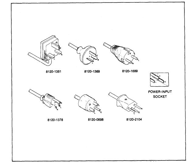
Model 5342A
Installation
2-9. Power Cable
2-10. The 5342A is shipped with a three-wire power cable. When the cable is connected to an appropriate ac power source, this cable connects the chassis to earth ground. The type of power cable plug shipped with each instrument depends on the country of destination. Refer to Figure 2-2 for the part numbers of the power cable and plug configurations available.
Figure 2-2. Power Cable HP Part Numbers versus Mains Plugs Available
WARNING
BEFORE SWITCHING ON THIS INSTRUMENT, THE
PROTECTIVE EARTH TERMINALS OF THIS INSTRU-
MENT MUST BE CONNECTED TO THE PROTECTIVE
CONDUCTOR OF THE (MAINS) POWER CORD. THE
MAINS PLUG SHALL ONLY BE INSERTED IN A
SOCKET OUTLET PROVIDED WITH A PROTECTIVE
EARTH CONTACT, THE PROTECTIVE ACTION MUST
NOT BE NEGATED BY THE USE OF AN EXTENSION
CORD (POWER CABLE) WITHOUT A PROTECTIVE
CONDUCTOR (GROUNDING).
2-2
Model 5342A
Installation
2-11. Operating Environment
2-12. TEMPERATURE. The 5342A may be operated in temperatures from 0°C to +55°C.
2-13. HUMIDITY. The 5342A may be operated in environments with humidity up to 95%. However, it should be protected from temperature extremes which cause condensation in the instrument.
2-14. ALTITUDE. The 5342A may be operated at altitudes up to 4,600 metres (15,000 feet).
2 - 1 5 . S T O R A G E A N D S H I P M E N T
2-16. Environment
2-17. The instrument may be stored or shipped in environments within the following limits:
TEMPERATURE . . . . . . . . . . . . . . . . . -40°C to +75°C
HUMIDITY . . . . . . . . . . . . . . . . . . . . . . . . . . Up to 95%
ALTITUDE . . . . . . . . . . . . . 7,620 metres (25,000 feet)
2-18. The instrument should also be protected from temperature extremes which cause condensation within the instrument.
2-19. Packaging
2-20. ORIGINAL PACKAGING. Containers and materials identical to those used in factory packaging are available through Hewlett-Packard offices. If the instrument is being returned to Hewlett-Packard for servicing, attach a tag indicating the type of service required, return address, model number, and full serial number. Also, mark the container FRAGILE to ensure careful handling. In any correspondence, refer to the instrument by model number and full serial number.
2-21. OTHER PACKAGING. |
The following general instructions should be used for repacking |
with commercially available |
materials: |
a.Wrap instrument in heavy paper or plastic. (If shipping to Hewlett-Packard office or
service center, attach tag indicating type of service required, return address, model number, and full serial number.)
b. Use strong shipping container. A double-wall carton made of 350-pound test material is adequate.
c. |
Use a |
layer of |
shock-absorbing material |
70 to 100 mm (3-to |
4-inch) thick around all sides |
|
of the instrument to provide firm cushioning and prevent |
movement inside container. |
|||
|
Protect |
control |
panel with cardboard. |
|
|
d. Seal shipping container securely.
e. Mark shipping container FRAGILE to ensure careful handling.
f. In any correspondence, refer to instrument by model number and full serial number.
2 - 2 2 . F I E L D I N S T A L L A T I O N O F O P T I O N S
2-23. Procedures for field installation of Options 001,002,003,004, and 011 are described in the following paragraphs.
2-3
Model 5342A
Installation
2-24. Part Numbers for Ordering Option Kits
2-25. To obtain the necessary parts for installation of an option, order by part number as listed below (refer to Section VI for ordering information):
Option |
Name |
Part Number |
|
001 |
High Stability Time Base |
HP Model 10544A |
|
002 |
Amplitude Measurement |
05342-60200 |
(Kit) |
003 |
Extended Dynamic Range |
05342-60201 |
(Kit) |
*004 |
Digital-to-Analog Converter |
05342-60202 |
(Kit) |
001 |
HP-IB I/O |
05342-60019 (HP-IB Assy.) |
|
|
|
05342-60029 (HP-IB |
Input Assy.) |
|
*NOTE |
|
|
If the instrument in which Option 004 is to be installed |
|
||
has a series number 1812 or lower, the U7 ROM on |
|
||
A14 Microprocessor will have to be replaced. Order |
|
||
U7 ROM Part Number 1818-0706 to replace the old |
|
||
U7 |
ROM (1818-0331). |
|
|
2-26. Installation of 10 MHz Oscillator Option 001
2-27. Option 001 consists of oven-controlled crystal oscillator time base 10544A, which has a pc card connector. Option 001 is installed in the same connector on the motherboard as the standard oscillator (A24). See Figure 8-44. To install Option 001, proceed as follows:
a.Remove the standard oscillator from A24 connector.
b.Install Option 001 oscillator into A24 connector.
c.Attach Option 001 oscillator to the motherboard by means of two 6/32X5/16 pan head screws. Install the screws from the bottom of the motherboard using star washers.
d.Perform Option 001 oscillator adjustment as described in paragraph 5-32.
2-28. Installation of Amplitude Measurement Option 002
2-29. Option 002 consists of U2 High Frequency Amplitude assembly and A27 Low Frequency Amplitude Assembly modules and the A16 Amplitude Assembly pc board. U2 is connected to the high frequency input of the 5342A, A27 is connected to the low frequency input and both of the modules are connected to the A16 board by the coax wires supplied. See photo of installed option, Figure 8-22, and schematic diagram, Figure 8-39. To install the components proceed as follows:
NOTE
The parts that comprise this option are listed in Table 6-5.
a.Remove the top and bottom covers and top plate from instrument.
b.Place instrument top down.
c.At inside front panel, disconnect cables from A1J1,J1J3,J25J1 (IF OUT lNT), and A25J2 (IF OUT EXT).
d.Solder one end of the white/red/green 14-inch wire (8120-0483) to AT1 feedthrough capacitor terminal on A25 Preamplifier assembly.
2-4

Model 5342A
Installation
e . Install coax assembly 8120-2268 through A22 motherboard from top of instrument at A16 slot. Place the wires through the holes as shown below:
NOTE
Prior to installing A27 Low Frequency Amplitude Assembly, connect the wires as described below.
f.Solder one end of the black/white/blue 14-inch wire (8120-0471) to C7 feedthrough capacitor terminal on A27.
g.Place heat shrinkable tubing (0890-0983) over connection at C7,
h.Place heat shrinkable tubing (0890-0983) over three of the coax wires (red, blue, and green) that were installed in step e. and solder these wires to the terminals listed below:
Coax Terminal
Red A27C10
Blue A27C9
Green A27C8
i.Apply heat to shrink the tubing at the connections made in step g and h.
j.Remove attaching nut from front panel N-type input connector and disconnect rigid coax W1 from J1 on U1 Sampler. Remove W1 from instrument.
k.Mount A27 Low Frequency Amplitude Assembly in the recessed angle of the casting behind front frame, see Figure 8-22. Attach A27 to casting with two pan head screws supplied. Place a star washer under the other screw.
l.The wire previously soldered to A27C10 has a black ground wire attached. Solder the end of this black wire to the ground lug installed in preceding step.
m.Solder the free end of white/red/green wire (other end connected to A25AT1 in step d) to A22 motherboard at XA16B, pin 3 (ATT).
NOTE
Prior to installing U2 High Frequency Amplitude Assembly, connect the color-coded wires as shown below. Place heat shrinkable tubing (0890-0983 for coax and 0890-0706 for single wires) over all connections to U2.
2-5

Model 5342A
Installation
n.Connect rigid coax (8120-2516) from U2 High Frequency Amplitude Assembly to J1 on
|
Sampler U1. Install U2 input connector through front panel. Fasten with attaching nut. |
o. |
Solder white/black/red wire (from U2) to A22 motherboard XA16B, pin |
p. |
Solder white/brown/red wire (from U2) to A22 motherboard XA16B, pin |
q. |
Harness the coax cables and wires with tie wraps supplied. |
r. |
Connect cable 05342-60119 from A27J1 to A1J3. |
s. |
Connect cable A1J3/A27J2 to A27J2. |
t. |
Reconnect A1J1,J1 (IF OUT INT) and J2 (IF OUT EXT) and harness with tie wrap. |
u.Harness the white cables with tie wraps supplied.
|
|
|
|
|
NOTE |
|
|
|
The ROM and U2 High Frequency Amplitude |
||
|
|
|
Assembly are supplied as a matched pair and are |
||
|
|
|
included |
under one replaceable part number |
|
|
|
|
(05342-80005). |
||
v. |
Install |
the |
ROM |
(supplied with option) into U3 socket on A16 (05342-60038) board. |
|
w. |
Replace resistor |
R2 on |
A16 board with a resistor of the value labeled on U2 assembly. |
||
x . Insert |
the plug of 8120-2268 cable into mating socket on A16 board (05342-60038) and |
||||
|
install |
A16 |
into |
connector XA16. |
|
y.Perform the Option 002 adjustments listed under paragraph 5-33 through 5-39 of this manual.
z. |
Perform the operational |
verification |
procedures in paragraphs 4-14, 4-15, and 4-17 |
|
of this manual. |
|
|
|
|
|
NOTE |
|
If the instrument does not meet the specified |
||
|
accuracy of ±1.5 dB as described in paragraph 4-14, |
||
|
perform the |
following |
procedures. |
Replace resistor R6 from the A27 Low Frequency Amplitude Assembly and replace with a resistor of a higher or lower value as shown below. For lower power readings increase the value and for higher power readings decrease the value of resistor R6 as follows:
dB Change |
R6 Changes (ohms) |
0.2 |
10 |
0.4 |
20 |
0.6 |
30 |
0.8 |
40 |
1.0 |
50 |
2-6

Model 5342A
Installation
2-30. Installation of Extended Dynamic Range Option 003
2-31. Option 003 consists of A16 Extended Dynamic Range Assembly (05342-60037) and U2 Attenuator Assembly (5088-7038). See Figure 8-22 for location of U2 (Option 002 or 003).
NOTE
The parts that comprise this option are listed at the end of Table 6-6.
a.Remove the top and bottom covers and top plate from instrument.
b.Place instrument top down.
c.At inside front panel, disconnect cable from A1J1,A1J3,A25J1 (IF OUT INT), and A25J2 (IF OUT EXT).
d.Solder one end of the white/red/green 14-inch wire (8120-0483) to AT1 feedthrough capacitor terminal on A25 Preamplifier Assembly.
e.Solder free end of white/red/green wire (other end connected to A25AT1 in step d) to A22 Motherboard at XA16B, pin 3 (ATT).
f. Solder white/bIack/red wire (from U2) to A22 Motherboard XA16B, pin 
g.Solder white/brown/red wire (from U2) to A22 Motherboard XA16B, pin 
h.Remove the N-type input connector from front panel and replace with U2 (5088-7038).
i.Connect rigid coax (supplied) from U2 to J1 on Sampler U1.
j.Install A16 board (05342-60037) into XA16 connector.
k. Perform the operational verification procedures in paragraphs 4-13 and 4-16 of this manual.
2-32. Installation of Digital-to-Analog Conversion (DAC) Option 004
2-33. Option 004 consists of an A2 Display Driver Assembly (05342-60028) that contains DAC circuitry added to the standard A2 circuit. Interconnecting wires are included with the Option 004 retrofit kit (05342-60202). Procedures for installation of Option 004 are as follows:
2-7

Model 5342A
Installation
a.Remove top and bottom covers, front frame and A1-A2 assemblies. Refer to disassembly procedures, paragraph 8-22.
b.Replace the original A2 board (05342-60002) with Option 004 A2 board (05342-60028) and reassemble unit.
c.If the series number of the instrument is 1812 or lower, the U7 ROM, 1818-0331 on the A14 Microprocessor board will have to be replaced with U7 ROM, 1818-0706 as described in step d. If instrument has the 1818-0706 ROM, proceed to step e.
CAUTION
ROM U7 is a large-scale MOS IC. Its inputs are susceptible to damage by high voltage and by static charges. Particular care should be exercised when servicing this IC or handling it under conditions where static charges can build up.
d.Remove top plate from 5342A. Remove A14 Microprocessor and replace ROM U7 part number 1818-0331 with part number 1818-0706. Install A14.
e.At bottom of 5342A connect coax cable to the connector at the bottom rear of A2 board labeled D/A OUTP. Solder the other end of this cable to the DAC OUT connector on the rear paneI.
f.Connect the white/gray wire to the pin (push-on) labeled LDA at bottom rear of A2 Display Driver board. Solder other end of wire to LDA terminal on A22 Motherboard as shown in figure below.
g.Connect red wire (+15V) and violet wire (-15V) to the proper terminals (push-on pins) on A2 Display Driver board (see Figure 8-25, component locator for location). Connect
other end of these wires to terminals on A22 Motherboard as shown in figure below.
h.Reassemble instrument and perform operational verification procedures in paragraph 4-27 of this manual.
2-34. Installation of HP-IB Option 011
2-35. Option 011 consist of printed-circuit assembly A15 and interconnection board A29. The interconnection board mounts inside the 5342A rear panel and is connected to A22 Motherboard via a cable strap. Procedures for installation of Option 011 are as follows (see photo of installed option, Figure 8-22):
a.Remove top and bottom covers and top panel from the 5342A.
b.Insert A15 assembly into A15 slot. See Figure 8-21 for location.
2-8

Model 5342A
Installation
c.If 5342A is equipped with Option 001 Oscillator, remove oscillator assembly by removing two attaching screws from A22 Motherboard.
N O TE
In the following step, make sure that the address switch (A29S1) is located as shown in Figure 8-20.
d.Insert the A29 Interconnection board (05342-60019) into the rear panel slots provided (from inside). Screw the two mounting studs (0380-0644) and washers (2100-3171) into the HP-IB connector to attach the board to the rear panel,
e.Connect the plug of the cable strap from A29 to J2 on A22 Motherboard with arrow on installed plug pointing toward front panel.
f.Perform the Option 011 HP-IB Verification in paragraph 4-19 of this manual.
g.Refer to paragraph 2-36 for HP-IB interconnection data and to paragraph 3-69 for programming information.
2-36. HP-IB Interconnections
2-37. HEWLETT-PACKARD INTERFACE BUS. Interconnection data concerning the rear panel HP-IB connector is provided in Figure 2-3. This connector is compatible with the HP 10631A/ B/C/D HP-IB cables. The HP-IB system allows interconnection of up to 15 (including the controller) HP-IB compatible instruments. The HP-IB cables have identical “piggy back” connectors on both ends so that several cables can be connected to a single source without special adapters or switch boxes. System components and devices may be connected in virtually any configuration desired. There must, of course, be a path from the calculator (or other controller) to every device operating on the bus. As a practical matter, avoid stacking more than three or four cables on any one connector. If the stack gets too large, the force on the stack produces great leverage which can damage the connector mounting. Be sure each connector is firmly (finger tight) screwed in place to keep it from working loose during use.
2-38. CABLE LENGTH RESTRICTIONS. To achieve design performance with the HP-IB, proper voltage levels and timing relationship must be maintained. If the system cable is too long, the lines cannot be driven properly and the system will fail to perform properly. Therefore, when interconnecting an HP-IB system, it is important to observe the following rules:
a.The total cable length for the system must be less than or equal to 20 metres (65 feet).
b.The total cable length for the system must be equal to or Iess than 2 metres (6.6 feet) times
the total number of devices connected to the bus.
c.The total number of instruments connected to the bus must not exceed 15.
2-39. 5342A Listen Address
2-40. The 5342A contains a rear panel HP-IB Instrument address selection switch. There are five
setting and changing the listen address are provided in Section III of this manual along with programming codes.
2-41. HP-IB Descriptions
2-42. A description of the HP-IB is provided in Section Ill of this manual, A study of this information is necessary if the user is not familiar with the HP-IB concept. Additional information concerning the design criteria and operation of the bus is available in IEEE Standard 488-1975, titled “IEEE Standard Digital Interface for Programmable Instrumentation”.
2-9

Model 5342A
Installation
Figure 2-3. Hewlett-Packard Interface Bus Connection
2-10

Model 5342A
Operation
SECTION Ill
OPERATION
3-1. INTRODUCTION
3-2. This section contains operating information including operating characteristics, descriptions of controls and indicators, and operating procedures.
3-3. OPERATING CHARACTERISTICS
3-4. The following paragraphs describe the operating ranges and modes, resolution, sample rate, AM and FM characteristics, and auto-amplitude discrimination. Front panel controls and indicators are described in Figure 3-1, rear paneI controls and connectors are described in Figure 3-2. Operating procedures are explained in Figure 3-3. Amplitude measurements (Option 002) are described in Figure 3-4. DAC operation (Option 004) is described in Figure 3-5.
3-5. Operating Ranges
3-6. There are two basic operating ranges: 10 Hz to 500 MHz and 500 MHz to 18 GHz. Frequencies in the lower range are measured directly while measurements in the 500 MHz to 18 GHz range are made indirectly by a harmonic heterodyne down-conversion technique. Provision is made to select either range by a front-panel slide switch. A separate input connector is provided for each range. When the range switch is in the 10 Hz—500MHz position, the signal at the BNC connector is routed to the direct count circuits of the 5342A. In this range, input impedance is selectable via the 50Ω−1— ΜΩ switch. When the range switch is in the 500 MHz—18 GHz range, the input signal is applied via the front-panel type N connector to the down-conversion circuits of the 5342A.
3-7. Resolution Keys
3-8. The best case resolution is the value represented by the least significant digit (LSD) in the display. In the 5342A, a maximum resolution of 1 Hz can be selected (by the pushbutton keys on the front panel labeled in blue, preceded by the blue key being pressed). The display is divided into four sections for ease of determining GHz,MHz,kHz,and Hz resolution. Half-sized used as space fillers within a section to improve interpretation of the display. For example, a signal measured to 100 kHz resolution will be displayed thus:
3-9. The pushbutton keys on the front panel under the RESOLUTION label are used for other purposes when the blue key is not in effect (has not been pressed). When the blue key has not been pressed, the keys are defined by the black number on the keys and are used to enter frequency offsets, manual center frequencies, and amplitude offsets as described in Figure 3-1.
3-1
Model 5342A
Operation
3-10. CHECK, DAC, and ENTER keys
3-11. The CHECK, DAC, and ENTER keys are used as described in Figure 3-1.
3-12. FREQ Keys
3-13. Two of the pushbutton keys on the front paneI under the FREQ label are used to select the automatic or manual mode of operation. The other keys in this section of the keyboard control the use of the RESOLUTON keys. Use of these keys is described in detail in Figure 3-1.
3-14. Automatic Mode
3-15. The automatic mode of operation is selected by pressing the AUTO key. Input signals in the 500 MHz—18 GHz range are acquired, measured, and displayed automatically. When power is initially turned on, the 5342A goes into this mode automatically.
3-16. Manual Mode
3-17. The manual mode of operation is selected by pressing the MAN (MHz) key. To operate in this mode, input signals in the 500 MHz-18 GHz range must be known to within 50 MHz and this frequency (called the manual center frequency) must be entered into the display prior to the measurement. Use of the manual mode is described in detail in Figure 3-3.
3-18. Offset Frequencies
3-19. It is sometimes desirable to add or subtract a constant to\from a frequency measurement. For example, by measuring a radio IF and knowing the LO, the counter can display the RF input when the LO frequency is entered as a positive offset. It may be easier to tune an oscillator to a specific frequency if the desired frequency is entered as a negative offset and the oscillator tuned until the counter reads zero. Frequency offsets are described in Figure 3-3.
3-20. Amplitude and Offset Measurements
3-21. When Amplitude Option 002 is installed, the amplitude is displayed in addition to the frequency of the input signal. The frequency is displayed to 1 MHz resolution in the five leftmost digits and the amplitude is displayed to 0.1 dB resolution in the four rightmost digits of the display. An arbitrary value can be selected as an amplitude offset and can be added to or subtracted from the measured value as described in Figure 3-4.
3-22. Digital-to-Analog Converter (DAC) Operation
3-23. When DAC Option 004 is installed, any three consecutive digits of the display can be selected and converted to a corresponding analog voltage output. The voltage is available at the BNC connector on the rear panel (labeled DAC OUT) and is between and 9.99 volts dc. For example, if the selected digits are the output is volts and if the selected digits are 999 the output is 9.99 volts dc. Operating procedures are listed in Figure 3-5.
3-24. SET, RESET, RECALL, and CHS Keys
3-25. The SET, RESET, RECALL, and CHS keys allow offsets and center frequencies to be entered, reset the measurement process, recall previous values, and change the sign of offsets as described in Figure 3-3.
3-26. SAMPLE RATE, GATE, and REMOTE
3-27. The SAMPLE RATE control adjusts the deadtime between the end of one measurement and the start of the next measurement. The duration of the measurement is determined by the
3-2
Loading...