


 Loading...
HP 640 ProBook G3 Notebook PC HP 650 ProBook G3 Notebook PC
Maintenance and Service Guide IMPORTANT! This document is intended for HP authorized service providers only.
© Copyright 2016 HP Development Company,
L.P.
AMD is a trademark of Advanced Micro Devices, Inc. Bluetooth is a trademark owned by its proprietor and used by HP Inc. under license. Intel is a trademark of Intel Corporation in the U.S. and other countries. Windows is either a registered trademark or trademark of Microsoft Corporation in the United States and/or other countries.
Product notice
This guide describes features that are common to most models. Some features may not be available on your computer.
Not all features are available in all editions of Windows. This computer may require upgraded and/or separately purchased hardware, drivers and/or software to take full advantage of Windows functionality. Windows 10 is automatically updated, which is always enabled. ISP fees may apply and additional requirements may apply over time for updates. See http://www.microsoft.com.
The information contained herein is subject to change without notice. The only warranties for HP products and services are set forth in the express warranty statements accompanying such products and services. Nothing herein should be construed as constituting an additional warranty. HP shall not be liable for technical or editorial errors or omissions contained herein.
First Edition: December 2016
Document Part Number: 912636-001

Safety warning notice
 WARNING! To reduce the possibility of heat-related injuries or of overheating the device, do not place the device directly on your lap or obstruct the device air vents. Use the device only on a hard, at surface. Do not allow another hard surface, such as an adjoining optional printer, or a soft surface, such as pillows or rugs or clothing, to block air ow. Also, do not allow the AC adapter to contact the skin or a soft surface, such as pillows or rugs or clothing, during operation. The device and the AC adapter comply with the user-accessible surface temperature limits de ned by the International Standard for Safety of Information Technology Equipment (IEC 60950-1).
iii
iv Safety warning notice

Table of contents
1 Product description ....................................................................................................................................... |
1 |
2 External component dent c t on .................................................................................................................. |
7 |
Right ....................................................................................................................................................................... |
7 |
Left ......................................................................................................................................................................... |
9 |
Display ................................................................................................................................................................. |
10 |
Top ........................................................................................................................................................................ |
11 |
TouchPad ........................................................................................................................................... |
11 |
Lights ................................................................................................................................................. |
12 |
Buttons, speakers, and ngerprint reader ........................................................................................ |
13 |
Keys ................................................................................................................................................... |
15 |
Using the hot keys ............................................................................................................................. |
17 |
Bottom ................................................................................................................................................................. |
18 |
Front ..................................................................................................................................................................... |
19 |
Rear ...................................................................................................................................................................... |
20 |
Locating system information .............................................................................................................................. |
20 |
3 Illustrated parts catalog .............................................................................................................................. |
22 |
Computer major components .............................................................................................................................. |
22 |
Display assembly subcomponents ...................................................................................................................... |
27 |
Mass storage devices ........................................................................................................................................... |
29 |
Miscellaneous parts ............................................................................................................................................. |
30 |
4 Removal and replacement procedures preliminary requirements .................................................................... |
32 |
Tools required ...................................................................................................................................................... |
32 |
Service considerations ......................................................................................................................................... |
32 |
Plastic parts ....................................................................................................................................... |
32 |
Cables and connectors ...................................................................................................................... |
33 |
Drive handling ................................................................................................................................... |
33 |
Grounding guidelines ........................................................................................................................................... |
34 |
Electrostatic discharge damage ........................................................................................................ |
34 |
Packaging and transporting guidelines .......................................................................... |
35 |
Workstation guidelines ................................................................................................... |
35 |
Equipment guidelines ..................................................................................................... |
36 |
v
5 Removal and replacement procedures for Authorized Service Provider parts ................................................... |
37 |
Component replacement procedures .................................................................................................................. |
37 |
Service door ....................................................................................................................................... |
37 |
Battery ............................................................................................................................................... |
38 |
Hard drive .......................................................................................................................................... |
39 |
Solid-state drive (select products only) ............................................................................................ |
41 |
WWAN module (select products only) ............................................................................................... |
42 |
WLAN module .................................................................................................................................... |
43 |
Optical drive ....................................................................................................................................... |
45 |
Keyboard ........................................................................................................................................... |
47 |
Memory .............................................................................................................................................. |
50 |
Hinge cover ........................................................................................................................................ |
53 |
Base enclosure .................................................................................................................................. |
55 |
System board .................................................................................................................................... |
57 |
Fan and heat sink assembly .............................................................................................................. |
59 |
Optical drive board ............................................................................................................................ |
62 |
Top cover and TouchPad .................................................................................................................... |
63 |
RTC battery ........................................................................................................................................ |
66 |
Speaker .............................................................................................................................................. |
68 |
Power button board .......................................................................................................................... |
69 |
Fingerprint reader (select products only) ......................................................................................... |
70 |
Smart card reader .............................................................................................................................. |
72 |
Near Field Communication module ................................................................................................... |
74 |
Audio board ....................................................................................................................................... |
76 |
Serial board ....................................................................................................................................... |
78 |
Display assembly ................................................................................................................................................. |
80 |
6 Computer Setup (BIOS), TPM, and HP Sure Start ............................................................................................. |
86 |
Using Computer Setup ......................................................................................................................................... |
86 |
Starting Computer Setup .................................................................................................................. |
86 |
Using a USB keyboard or USB mouse to start Computer Setup (BIOS) .......................... |
86 |
Navigating and selecting in Computer Setup ................................................................................... |
86 |
Restoring factory settings in Computer Setup ................................................................................. |
87 |
Updating the BIOS ............................................................................................................................. |
87 |
Determining the BIOS version ......................................................................................... |
87 |
Downloading a BIOS update ........................................................................................... |
88 |
Changing the boot order using the f9 prompt .................................................................................. |
89 |
TPM BIOS settings (select products only) ........................................................................................................... |
89 |
Using HP Sure Start (select products only) ......................................................................................................... |
89 |
vi
7 Using HP PC Hardware Diagnostics (UEFI) ....................................................................................................... |
90 |
Downloading HP PC Hardware Diagnostics (UEFI) to a USB device .................................................................... |
90 |
8 Backing up, restoring, and recovering ........................................................................................................... |
92 |
Creating recovery media and backups ................................................................................................................ |
92 |
Creating HP Recovery media (select products only) ......................................................................... |
92 |
Using Windows tools ........................................................................................................................................... |
93 |
Restore and recovery ........................................................................................................................................... |
94 |
Recovering using HP Recovery Manager ........................................................................................... |
94 |
What you need to know before you get started ............................................................. |
94 |
Using the HP Recovery partition (select products only) ................................................. |
95 |
Using HP Recovery media to recover .............................................................................. |
95 |
Changing the computer boot order ................................................................................ |
96 |
Removing the HP Recovery partition (select products only) ......................................... |
97 |
9 pec c t ons .............................................................................................................................................. |
98 |
Computer speci cations ...................................................................................................................................... |
98 |
35.56 cm (14-in) display speci cations ............................................................................................................ |
100 |
39.62 cm (15.6-in) display speci cations ......................................................................................................... |
103 |
Hard drive speci cations ................................................................................................................................... |
104 |
Solid-state drive speci cations ......................................................................................................................... |
107 |
10 Power cord set requirements .................................................................................................................... |
110 |
Requirements for all countries .......................................................................................................................... |
110 |
Requirements for speci c countries and regions ............................................................................................. |
110 |
11 Statement of memory volatility ................................................................................................................ |
112 |
Nonvolatile memory usage ............................................................................................................................... |
114 |
Questions and answers ..................................................................................................................................... |
116 |
Using HP Sure Start (select models only) .......................................................................................................... |
117 |
12 Recycling ................................................................................................................................................ |
118 |
Index ........................................................................................................................................................... |
119 |
vii
viii

1Product description
Category |
Description |
|
|
Product Name |
HP 640 ProBook G3 Notebook PC |
|
HP 650 ProBook G3 Notebook PC |
|
|
Processors |
7th Generation Intel® Core™ i3 Processor, Kabylake U, dual-core, BGA: |
|
i3-7100U (Kit processor) |
|
7th Generation Intel® Core™ i5 Processor, Kabylake U, dual-core, BGA: |
|
i5-7200U (Kit processor) |
|
i5-7300U (Roadmap processor) |
|
7th Generation Intel® Core™ i7 Processor, Kabylake U, dual-core, BGA: |
|
i7-7600U (Roadmap processor) |
|
7th Generation Intel® Core i5 Processor, Kabylake H, Quad Core, BGA ULT: |
|
(select products only) |
|
i5-7440HQ (Roadmap processor) 45w/35w cTDP (select products only) |
|
7th Generation Intel® Core i7 Processor, Kabylake H, Quad Core, BGA ULT: |
|
(select products only) |
|
i7-7820HQ (Roadmap processor) 45w 45w/35w cTDP (select products only) |
|
|
Chipset |
Intel Kabylake Chipset—The chipset is integrated with the processor. |
|
Skylake PCH QM175 (select products only) |
|
|
Graphics |
Intel UMA Graphics (GT2) - with shared video memory |
|
AMD Radeon R7 M465 (128-bit) w/2 GB GDDR5 (128Mb x 32, 1.35V, 5Gbps, |
|
Qty 4) |
|
Supporting 2 display port and 1 D-sub through docking |
|
Supports 3 independent displays when on the Quest 2 dock |
|
|
Panel |
Anti-glare panels for 14” products: |
|
14.0" HD AG SVA 45% CG 220 nits eDP 1.2 Slim (1366x768) |
|
14.0" HD AG SVA 45% CG 220 nits eDP 1.2 Slim (1366x768) with camera |
|
14.0" HD AG SVA 45% CG 220 nits eDP 1.2 Slim (1366x768) with WWAN |
|
14.0" HD AG SVA 45% CG 220 nits eDP 1.2 Slim (1366x768) with camera |
|
and with WWAN |
|
14.0" FHD AG SVA 60% CG 300 nits eDP 1.2 + PSR slim (1920x1080) |
|
14.0" FHD AG SVA 60% CG 300 nits eDP 1.2 + PSR slim (1920x1080) with |
|
camera |
|
14.0" FHD AG SVA 60% CG 300 nits eDP 1.2 + PSR slim (1920x1080) with |
|
WWAN |
|
14.0" FHD AG SVA 60% CG 300 nits eDP 1.2 + PSR slim (1920x1080) with |
|
camera and WWAN |
1

Category |
Description |
|
|
|
14.0" FHD Slim eDP SVA 60% 300 nits (1920 x 1080) Touch with camera |
|
and with WWAN |
|
Chemically Strengthened Soda Lime Glass, GF2-MM - Air-Gap Bonded |
|
Anti-glare panels for 15" products with LED backlight: |
|
15.6" HD AG SVA 45% CG 220 nits eDP 1.2 Slim (1366x768) |
|
S15.6" HD AG SVA 45% CG 220 nits eDP 1.2 Slim (1366x768) with camera |
|
15.6" HD AG SVA 45% CG 220 nits eDP 1.2 Slim (1366x768) with WWAN |
|
15.6" HD AG SVA 45% CG 220 nits eDP 1.2 Slim (1366x768) with camera |
|
and with WWAN |
|
15.6" FHD AG SVA 60% CG 300 nits eDP 1.2 + slim (1920x1080) |
|
15.6" FHD AG SVA 60% CG 300 nits eDP 1.2 + slim (1920x1080) with |
|
camera |
|
15.6" FHD AG SVA 60% CG 300 nits eDP 1.2 + slim (1920x1080) with WWAN |
|
15.6" FHD AG SVA 60% CG 300 nits eDP 1.2 + slim (1920x1080) with |
|
camera and WWAN |
|
14.0" FHD Slim eDP SVA 60% 300 nits (1920 x 1080) Touch with camera |
|
and with WWAN |
|
Chemically Strengthened Soda Lime Glass, GF2-MM - Air-Gap Bonded |
|
|
Memory |
Two SODIMM slots |
|
Both slots are customer accessible / upgradeable |
|
DDR4 PC4 SODIMMS - System supports run rate at 2133—Supports Dual |
|
Channel Memory up to 16 GB. |
|
DDR4 PC4 SODIMMS - System supports run rate at 2400 (select products |
|
only) |
|
4096 MB Total System Memory (4096 MB x 1) |
|
8192 MB Total System Memory (4096 MB x 2) |
|
8192 MB Total System Memory (8192 MB x 1) |
|
12288 MB Total System Memory (8192 MB + 4096 MB) |
|
16384 MB Total System Memory (8192 MB x 2) |
|
|
Hard drive |
Supports SATA3, 7mm, 2.5" HDDs: |
|
500GB 7200 RPM |
|
500GB 7200 RPM self-encrypting drive (Opal 2) |
|
500GB 7200 RPM (FIPS-140-2) (Opal 2) |
|
1TB 5400 RPM |
|
500GB 5400 rpm Hybrid |
|
|
Solid-state drive |
M.2 (2280) Solid State Drive |
|
128GB M2 SATA-3 SS Value |
|
256GB SATA-3 SS TLC (Opal 2) |
|
512GB PCIe Value |
|
256GB PCIe Gen3x4 NVMe SS TLC |
2Chapter 1 Product description
Category |
Description |
|
|
|
360GB PCIe Gen3x4 SS TLC (Intel) |
|
512GB PCIe Value |
|
512GB PCIe Gen3x4 NVMe SS TLC |
|
512GB SATA SS TLC (FIPS) |
|
512GB PCIe Gen3x4 NVMe SS TLC (Opal 2) |
|
512GB PCIe Gen3x4 NVMe SS MLC |
|
|
Optical drive (select products only) |
SATA 9.0mm optical drives: |
|
DVD-ROM (defeatured combo) |
|
DVD+/-RW SuperMulti DL |
|
Blu-ray WriterSATA |
|
Supports "No Optical weight saver" option |
|
|
Audio and video |
Microphone (Dual Array) only for products without a webcam |
|
Microphone (Dual Array) only for products with a webcam |
|
Camera (720p) |
|
Supports “no camera” option |
|
Stereo Speakers (2) |
|
|
Serial port |
15” products only |
|
RS-232 /Serial Port |
|
Supports "no serial port" option” |
|
|
Ethernet |
Intel I219LM (Jacksonville-LM) 10/100/1000 Ethernet NIC with dash |
|
Support - supports roadmap processors |
|
Intel I219V (Jacksonville-V) 10/100/1000 Ethernet NIC with dash Support - |
|
supports kit processors |
|
The following support HBMA (via UEFI PXE boot and Windows OS): |
|
embedded NIC, Quest, HP3005, Ace Plus, Bert, and Ernie |
|
The following dongles only support S3 wake on LAN: Ace Plus |
|
S3/S4/S5 wake on LAN |
|
|
Wireless LAN |
WPAN Bluetooth: |
|
BT 4.0 only supported via Realtek Sanji2 |
|
BT 4.2 only supported via Intel Sandy Peak, Windstorm Peak vPro & |
|
Winstorm Peak non-vPro |
|
WLAN: |
|
WLAN options via Minicard connector: |
|
Intel Dual band wireless-AC 8265 802.11AC 2x2 WiFi + BT 4.2 Combo |
|
Adaptor (vPro) (Windstorm Peak) |
|
Intel Dual band wireless-AC 8265 802.11AC 2x2 WiFi + BT 4.2 Combo |
|
Adaptor (non-vPro) (Windstorm Peak non-vPro) |
|
Intel Dual band wireless-AC 3168 802.11AC 1x1 WiFi + BT 4.2 Combo |
|
Adaptor (non-vPro) (Sandy Peak 1) |
3

Category |
Description |
|
|
|
Realtek RTL8723BE-VB 802.11b/g/n 1x1 Wi-Fi + BT4.0 Combo Adapter |
|
(Sanji2) |
|
Intel Dual Band Wireless-AC 7265 D1 802.11 AC 2x2 WiFi + BT 4.2 Combo |
|
Adapter (non-vPro) Stone Peak 2 D1 |
|
WLAN Antennas (2) con ured at top of panel on all units) |
|
Bluetooth Disabled IOPT |
|
Support "No WLAN/No BT" option |
|
Support for Miracast |
|
Support for S3/S4 wake on Wireless LAN (Intel Only.) |
|
Support for WiFi SAR in BIOS (Intel Card Only.) |
|
Support for HP Sure Connect |
|
NFC (select products only) |
|
Integrated NFC Galapagos NXP NPC100 I2C NCI 10mmx25mm module |
|
NFC Antenna (con gured on NFC SKUs only) |
|
NFC Cable |
|
Supports "No NFC" option |
|
|
Wireless WAN (select products only) |
SIM Module (3FF/micro SIM): (user accessible on side of unit) |
|
WWAN options via connector: |
|
Foxconn HP lt4120 LTE/EVDO/HSPA+ w/GPS M.2 (Amstel) (WW, except |
|
Indonesia, China, India, Japan) |
|
Huawei HP lt4132, LTE/HSPA+ w/GPS M.2 (Macan) (APJ, LA, EMEA) |
|
Fibocom HP hs3210 WW HSPA+ w/o GPS (Wrangler 2) |
|
WWAN Antennas (2) (world wide 5 band, con ured at top of panel on all |
|
units) |
|
Supports "No WWAN" option |
|
Supports WWAN After Market Option (for Europe, Middle East, and Africa |
|
only) |
|
|
External media cards |
SD Media Reader slot supports SD, SDHC, and SDXC. |
|
|
Ports |
VGA (Dsub 15 pin) supporting 1920 x 1200 external resolution @ 60Hz |
|
Hot Plug / Unplug and auto detect |
|
DisplayPort 1.2 |
|
(1) USB Type C Charging Port |
|
(2) USB 3.0 Port (1 Charging) |
|
RJ-45 / Ethernet |
|
Docking connector |
|
Headphone / Microphone (Combo jack) |
|
RS-232 /Serial Port (select products only) |
|
AC Port (4.5mm) |
|
|
Docking |
Quest 2 dock support |
|
|
4Chapter 1 Product description

Category |
Description |
|
|
|
|
Keyboard/pointing devices |
HP Advanced Keyboard |
|
|
Touchpad, Spill-resistant with drain |
|
|
Touchpad, Spill-resistant with drain, DuraKeys and backlit |
|
|
Dual Point, Spill-resistant with drain, DuraKeys and backlit |
|
|
|
|
Power requirements |
Battery: |
|
|
3-cell HP Long Life Prismatic 48 WHr ( 4.21 Ahr ) Battery |
|
|
|
|
|
AC adapter: |
|
|
45 Watt Smart nPFC 3 pin RC 4.5mm connector - non slim |
|
|
45 Watt Smart nPFC 3 pin RC 4.5mm connector - non slim 2 prong |
|
|
65 Watt Smart nPFC 3 pin RC 4.5mm connector |
|
|
65 Watt Smart nPFC EM 4.5mm connector |
|
|
90 Watt Smart PFC 3 pin 4.5mm (select products only) |
|
|
|
|
|
Power Cord (localized): |
|
|
2-wire plug - 1m |
|
|
3-wire plug - 1.8m |
|
|
3-wire plug - 1m |
|
|
|
|
Security |
Supports Security Lock |
|
|
TPM 2.0 ( n neon; soldered down) |
|
|
Fingerprint Reader (select products only) |
|
|
Integrated Smart Card Reader (Active) |
|
|
Preboot Authentication (Password, Smart Card) |
|
|
|
|
Operating system |
Operating System Version: |
|
|
Windows 10: Redstone 1 |
|
|
Preinstalled: |
|
|
● |
Win 10 Home 64 |
|
● |
Win 10 Home 64 Single Language |
|
● |
Win 10 Home 64 CPPP |
|
● |
Win 10 Home 64 High-end CPPP |
|
● |
Win 10 Home 64 High-end |
|
● |
Win 10 Home 64 High-end Single Language |
|
● |
Win 10 Home 64 StF MSNA for Higher Education Strategic |
|
● |
Win 10 Pro 64 |
|
● |
Win 10 Pro 64 Shape the Future MSNA High End |
|
● |
Win 10 Pro 64 Shape the Future Standard |
|
● |
Win 10 Pro 64 Shape the Future Strategic |
5

Category |
Description |
|
|
|
|
|
● |
FreeDOS 2.0 |
|
|
|
Serviceability |
End user replaceable parts: |
|
|
AC adapter |
|
|
|
|
6Chapter 1 Product description
2 External component dent c t on
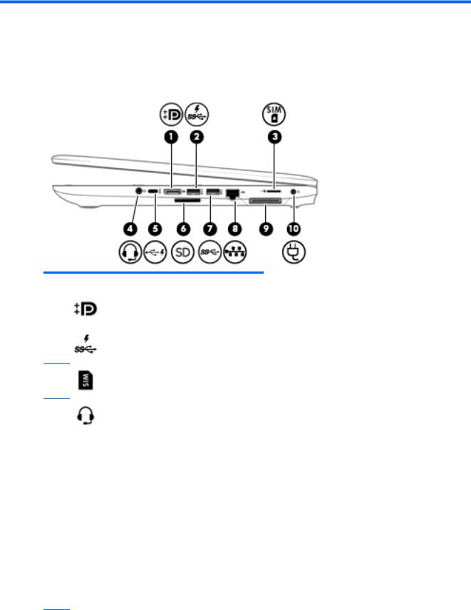
Right
Component |
|
Description |
|
|
|
(1) |
Dual-Mode DisplayPort |
Connects an optional digital display device, such as a high- |
|
|
performance monitor or projector. |
|
|
|
(2) |
USB 3.x charging port |
When the computer is on, connects and charges a USB device, |
|
|
such as a cell phone, camera, activity tracker, or smartwatch, |
|
|
and provides high-speed data transfer. |
(3) |
Micro SIM card slot (select products only) |
Supports a wireless micro subscriber identity module (micro SIM) card.
(4) |
Audio-out (headphone)/Audio-in (microphone) |
Connects optional powered stereo speakers, headphones, |
|
|
combo jack |
earbuds, a headset, or a television audio cable. Also connects an |
|
|
|
optional headset microphone. This jack does not support |
|
|
|
optional microphone-only devices. |
|
|
|
WARNING! To reduce the risk of personal injury, adjust the |
|
|
|
volume before putting on headphones, earbuds, or a headset. |
|
|
|
For additional safety information, refer to the Regulatory, |
|
|
|
Safety, and Environmental Notices. |
|
|
|
To access this guide: |
|
|
|
1. |
Type support in the taskbar search box, and then select |
|
|
|
the HP Support Assistant app. |
|
|
|
‒ or – |
|
|
|
Click the question mark icon in the taskbar. |
|
|
2. |
Select My PC, select the pec c t ons tab, and then |
|
|
|
select User Guides. |
NOTE: When a device is connected to the jack, the computer speakers are disabled.
Right 7
Component |
|
Description |
|
|
|
|
|
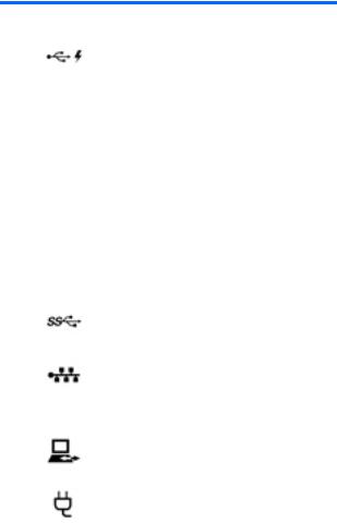
(5) |
USB Type-C charging port |
When the computer is on, connects and charges a USB device |
|
|
|
that has a Type-C connector, such as a cell phone, camera, |
|
|
|
activity tracker, or smartwatch, and provides data transfer. |
|
|
|
|
|
(6) |
Memory card reader |
Reads optional memory cards that store, manage, share, or |
|
|
|
access information. |
|
|
|
To insert a card: |
|
|
|
1. |
Hold the card label-side up, with the connectors facing the |
|
|
|
computer. |
|
|
2. |
Insert the card into the memory card reader, and then |
|
|
|
press in on the card until it is rmly seated. |
|
|
To remove a card: |
|
|
|
▲ |
Press in on the card, and then remove it from the memory |
|
|
|
card reader. |
|
|
|
|
(7) |
USB 3.x port |
Connects a USB device, such as a cell phone, camera, activity |
|
|
|
tracker, or smartwatch, and provides data transfer. |
|
|
|
|
|
(8) |
RJ-45 (network) jack/status lights |
Connects a network cable. |
|
|
|
● |
Green (right): The network is connected. |
|
|
● |
Amber (left): Activity is occurring on the network. |
|
|
|
|
(9) |
Docking port |
Connects an optional docking device. |
|
|
|
|
|
(10) |
Power connector |
Connects an AC adapter. |
|
|
|
|
|
8 Chapter 2 External component identi cation
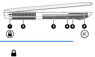
Left
Component |
|
Description |
|
|
|
(1) |
Security cable slot |
Attaches an optional security cable to the computer. |
|
|
NOTE: The security cable is designed to act as a deterrent, but |
|
|
it may not prevent the computer from being mishandled or |
|
|
stolen. |
|
|
|
(2) |
Vent |
Enables air ow to cool internal components. |
|
|
NOTE: The computer fan starts up automatically to cool |
|
|
internal components and prevent overheating. It is normal for |
|
|
the internal fan to cycle on and o during routine operation. |
|
|
|
(3) |
Optical drive (select products only) |
Depending on your computer model, reads an optical disc or |
|
|
reads and writes to an optical disc. |
|
|
|
(4) |
Optical drive light (select products only) |
On: The optical drive is in use. |
|
|
: The optical drive is not in use. |
|
|
|
(5) |
Optical drive eject button (select products only) |
Releases the optical drive disc tray. |
|
|
|
(6) |
Smart card reader (depending on the |
Supports optional smart cards. |
|
con guration) |
|
|
|
|
Left 9
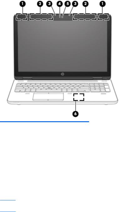
Display
Component |
Description |
|
|
|
|
(1) |
WLAN antennas* |
Send and receive wireless signals to communicate with wireless local |
|
|
area networks (WLANs). |
|
|
|
(2) |
WWAN antennas* |
Send and receive wireless signals to communicate with wireless wide |
|
|
area networks (WWANs). |
|
|
|
(3) |
Internal microphones |
Record sound. |
|
|
|
(4) |
Webcam light (select products only) |
On: The webcam is in use. |
|
|
|
(5) |
Webcam (select products only) |
Records video and captures photographs. Some models allow you to |
|
|
video conference and chat online using streaming video. |
To use the webcam:
▲ Type camera in the taskbar search box, and then select
Camera.
(6)Near Field Communication (NFC) tapping area* (select products only)
Tap another NFC-enabled device to the NFC tapping area to transfer les.
*The antennas are not visible from the outside of the computer. For optimal transmission, keep the areas immediately around the antennas free from obstructions.
For wireless regulatory notices, see the section of the Regulatory, Safety, and Environmental Notices that applies to your country or region.
To access this guide:
1.Type support in the taskbar search box, and then select the HP Support Assistant app.
‒ or –
Click the question mark icon in the taskbar.
10 Chapter 2 External component identi cation
Component |
Description |
|
|
2. Select My PC, select the pec |
c t ons tab, and then select User Guides. |
|
|
Top
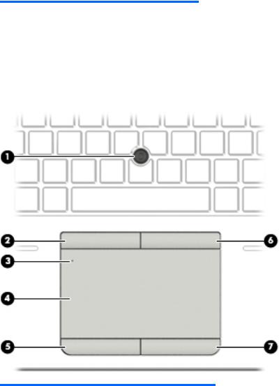
TouchPad
Component |
|
Description |
|
|
|
|
|
(1) |
Pointing stick (select products only) |
Moves the pointer and selects or activates items on the screen. |
|
|
|
|
|
(2) |
Left pointing stick button (select products only) |
Functions like the left button on an external mouse. |
|
|
|
|
|
(3) |
TouchPad light |
● |
On: The TouchPad is o . |
|
|
● |
: The TouchPad is on. |
|
|
|
|
(4) |
TouchPad zone |
Reads your nger gestures to move the pointer or activate |
|
|
|
items on the screen. |
|
|
|
|
|
(5) |
Left TouchPad button |
Functions like the left button on an external mouse. |
|
|
|
|
|
(6) |
Right pointing stick button (select products |
Functions like the right button on an external mouse. |
|
|
only) |
|
|
|
|
|
|
(7) |
Right TouchPad button |
Functions like the right button on an external mouse. |
|
|
|
|
|
Top 11
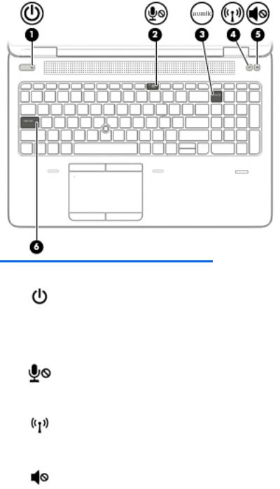
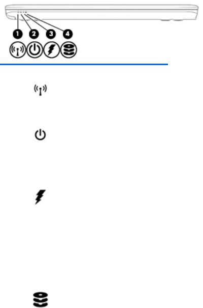
Lights
Component |
|
Description |
|
|
|
|
|
(1) |
Power light |
● |
On: The computer is on. |
|
|
● |
Blinking: The computer is in the Sleep state, a power-saving |
|
|
|
state. The computer shuts o power to the display and |
|
|
|
other unneeded components. |
|
|
● |
: The computer is o or in Hibernation. Hibernation is a |
|
|
|
power-saving state that uses the least amount of power. |
|
|
|
|
(2) |
Microphone mute light |
● |
Amber: Microphone sound is o . |
|
|
● |
: Microphone sound is on. |
|
|
|
|
(3) |
Num lk light |
On: Num lk is on. |
|
|
|
|
|
(4) |
Wireless light |
On: An integrated wireless device, such as a wireless local area |
|
|
|
network (WLAN) device and/or a Bluetooth® device, is on. |
|
|
|
NOTE: On some models, the wireless light is amber when all |
|
|
|
wireless devices are o . |
|
|
|
|
|
(5) |
Mute light |
● |
Amber: Computer sound is o . |
|
|
● |
White: Computer sound is on. |
|
|
|
|
(6) |
Caps lock light |
On: Caps lock is on, which switches the key input to all capital |
|
|
|
letters. |
|
|
|
|
|
12 Chapter 2 External component identi cation
Buttons, speakers, and n erpr nt reader
Component |
|
Description |
|
|
|
|
|
|
|
(1) |
Power button |
● |
When the computer is o press the button to turn on the |
|
|
|
|
computer. |
|
|
|
● |
When the computer is on, press the button brie y to initiate |
|
|
|
|
Sleep. |
|
|
|
● |
When the computer is in the Sleep state, press the button |
|
|
|
|
brie y to exit Sleep. |
|
|
|
● |
When the computer is in Hibernation, press the button |
|
|
|
|
brie y to exit Hibernation. |
|
|
|
CAUTION: Pressing and holding down the power button results |
||
|
|
in the loss of unsaved information. |
|
|
|
|
If the computer has stopped responding and shutdown |
||
|
|
procedures are ine ective press and hold the power button for at |
||
|
|
least 5 seconds to turn o the computer. |
|
|
|
|
To learn more about your power settings, see your power |
||
|
|
options. |
|
|
|
|
▲ |
Type power options in the taskbar search box, and then |
|
|
|
|
select Power Options. |
|
|
|
|
‒ or – |
|
|
|
|
Right-click the Power meter icon |
, and then select |
|
|
|
Power Options. |
|
|
|
|
|
|
(2) |
Speakers |
Produce sound. |
|
|
|
|
|
|
|
Top 13

Component |
|
Description |
|
|
|
(3) |
Wireless button |
Turns the wireless feature on or o but does not establish a |
|
|
wireless connection. |
|
|
A wireless network must be set up before a wireless connection is |
|
|
possible. |
|
|
|
(4) |
Volume mute button |
Mutes and restores speaker sound. |
|
|
|
(5) |
Fingerprint reader (select products only) |
Allows a ngerprint logon to Windows®, instead of a password |
|
|
logon. |
|
|
|
14 Chapter 2 External component identi cation

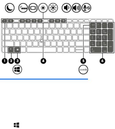
Keys
 NOTE: Refer to the illustration that most closely matches your computer.
Component |
|
Description |
|
|
|
(1) |
esc key |
Displays system information when pressed in combination with |
|
|
the fn key. |
|
|
|
(2) |
fn key |
Executes frequently used system functions when pressed in |
|
|
combination with a function key, the num lk key, the esc key, or |
|
|
other key. |
|
|
See Using the hot keys on page 17 |
|
|
|
(3) |
Windows key |
Opens the Start menu. |
|
|
NOTE: Pressing the Windows key again will close the Start |
|
|
menu. |
|
|
|
(4) |
Function keys |
Execute frequently used system functions in combination with |
|
|
the fn key. |
|
|
See Using the hot keys on page 17. |
|
|
|
(5) |
Embedded numeric keypad |
A numeric keypad superimposed over the keyboard alphabet |
|
|
keys that enables you to add, subtract, and perform other |
|
|
numeric tasks. When num lk is pressed, the keypad can be used |
|
|
like an external numeric keypad. Each key on the keypad |
|
|
performs the function indicated by the icon in the upper-right |
|
|
corner of the key. |
|
|
NOTE: If the keypad function is active when the computer is |
|
|
turned o that function is reinstated when the computer is |
|
|
turned back on. |
|
|
|
(6) |
Windows application key |
Displays options for a selected object. |
|
|
|
(7) |
num lk key |
Turns the embedded numeric keypad on and o . |
|
|
|
Top 15
Component |
|
Description |
|
|
|
(1) |
esc key |
Displays system information when pressed in combination with |
|
|
the fn key. |
|
|
|
(2) |
fn key |
Executes frequently used system functions when pressed in |
|
|
combination with a function key, the num lk key, the esc key, or |
|
|
other key. |
|
|
See Using the hot keys on page 17 |
|
|
|
(3) |
Windows key |
Opens the Start menu. |
|
|
NOTE: Pressing the Windows key again will close the Start |
|
|
menu. |
|
|
|
(4) |
Function keys |
Execute frequently used system functions in combination with |
|
|
the fn key. |
|
|
See Using the hot keys on page 17. |
|
|
|
(5) |
num lk key |
Alternates between the navigational and numeric functions on |
|
|
the integrated numeric keypad. |
|
|
|
(6) |
Integrated numeric keypad |
A separate keypad to the right of the alphabet keyboard that |
|
|
enables you to add, subtract, and perform other numeric tasks. |
|
|
When num lk is on, the integrated keypad can be used like an |
|
|
external numeric keypad. |
|
|
|
16 Chapter 2 External component identi cation

Using the hot keys
To use a hot key:
▲Press the fn key, and then press one of the keys listed in the following table.
Press fn+function key Description
Initiates Sleep, which saves your information in system memory. The display and other system components turn o and power is conserved. To exit Sleep, brie y press the power button.
CAUTION: To reduce the risk of information loss, save your work before initiating Sleep.
Turns the keyboard backlight o or on.
NOTE: To conserve battery power, turn o this feature.
Switches the screen image between display devices connected to the system. For example, if a monitor is connected to the computer, repeatedly pressing this key alternates the screen image from the computer display to the monitor display to a simultaneous display on both the computer and the monitor.
Decreases the screen brightness incrementally as long as you hold down the key.
Increases the screen brightness incrementally as long as you hold down the key.
Decreases speaker volume incrementally while you hold down the key.
Increases speaker volume incrementally while you hold down the key.
Mutes the microphone.
Top 17
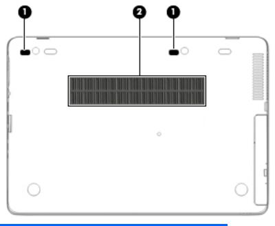
Bottom
Component |
|
Description |
|
|
|
(1) |
Docking station support holes |
Support an optional docking station. |
|
|
|
(2) |
Vent |
Enables air ow to cool internal components. |
|
|
NOTE: The computer fan starts up automatically to cool |
|
|
internal components and prevent overheating. It is normal |
|
|
for the internal fan to cycle on and o during routine |
|
|
operation. |
|
|
|
18 Chapter 2 External component identi cation
Front
Component |
|
Description |
|
|
|
|
|
(1) |
Wireless light |
On: An integrated wireless device, such as a wireless local |
|
|
|
area network (WLAN) device and/or a Bluetooth® device |
|
|
|
and/or a WWAN device, is on. |
|
|
|
NOTE: On some models, the wireless light is amber when |
|
|
|
all wireless devices are o . |
|
|
|
|
|
(2) |
Power light |
● |
On: The computer is on. |
|
|
● |
Blinking: The computer is in the Sleep state, a power- |
|
|
|
saving state. The computer shuts o power to the |
|
|
|
display and other unneeded components. |
|
|
● |
: The computer is o or in Hibernation. |
|
|
|
Hibernation is a power-saving state that uses the |
|
|
|
least amount of power. |
|
|
|
|
(3) |
Battery light |
When AC power is connected: |
|
|
|
● |
White: The battery charge is greater than 90 percent. |
|
|
● |
Amber: The battery charge is from 0 to 90 percent. |
|
|
● |
: The battery is not charging. |
When AC power is disconnected (battery not charging):
|
|
● |
Blinking amber: The battery has reached a low |
|
|
|
battery level. When the battery has reached a critical |
|
|
|
battery level, the battery light begins blinking |
|
|
|
rapidly. |
|
|
● |
: The battery is not charging. |
|
|
|
|
(4) |
Drive light |
● |
Blinking white: The hard drive is being accessed. |
|
|
● |
Amber: HP 3D DriveGuard has temporarily parked the |
|
|
|
hard drive. |
|
|
|
|
Front 19
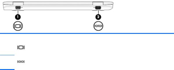
Rear
Component |
|
Description |
|
|
|
(1) |
External monitor port |
Connects an external VGA monitor or projector. |
(2) |
Serial port (select products only) |
Connects an optional device such as a serial modem, mouse, or printer.
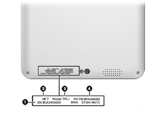
Locating system information
Important system information is located on the bottom edge of the tablet or on the keyboard base. You may need the information when travelling internationally or when you contact support:
(1): Serial number
(2): Product number
(3): Model number
(4): Warranty period
20 Chapter 2 External component identi cation
Using Windows, brie y press the fn+esc key combination to display the System Information screen, which provides the product name and serial number of your computer, as well as information about the memory, processor, BIOS, and keyboard.
Locating system information 21

3Illustrated parts catalog
Computer major components
 NOTE: HP continually improves and changes product parts. For complete and current information on supported parts for your computer, go to http://partsurfer.hp.com, select your country or region, and then follow the on-screen instructions.


 NOTE: Details about your computer, including model, serial number, product key, and length of warranty, are on the service tag at the bottom of your computer. See Locating system information on page 20 for details.
22 Chapter 3 Illustrated parts catalog
Loading...