


 Loading...
Maintenance & Service Guide
HP Compaq 6005 Pro Business PC
© Copyright 2009 Hewlett-Packard Development Company, L.P. The information contained herein is subject to change without notice.
Microsoft and Windows are trademarks of Microsoft Corporation in the U.S. and other countries.
The only warranties for HP products and services are set forth in the express warranty statements accompanying such products and services. Nothing herein should be construed as constituting an additional warranty. HP shall not be liable for technical or editorial errors or omissions contained herein.
This document contains proprietary information that is protected by copyright. No part of this document may be photocopied, reproduced, or translated to another language without the prior written consent of Hewlett-Packard Company.
Maintenance & Service Guide
HP Compaq 6005 Pro Business
PC
First Edition (September 2009)
Document Part Number: 581653-001

About This Book
 WARNING! Text set off in this manner indicates that failure to follow directions could result in bodily harm or loss of life.
 CAUTION: Text set off in this manner indicates that failure to follow directions could result in damage to equipment or loss of information.
 NOTE: Text set off in this manner provides important supplemental information.
iii
iv About This Book

Table of contents
1 Product Features |
|
Microtower Chassis .............................................................................................................................. |
1 |
Standard Configuration Features ......................................................................................... |
1 |
Front Panel Components ..................................................................................................... |
2 |
Media Card Reader Components ........................................................................................ |
3 |
Rear Panel Components ..................................................................................................... |
4 |
Serial Number Location ....................................................................................................... |
5 |
Small Form Factor ................................................................................................................................ |
6 |
Standard Configuration Features ......................................................................................... |
6 |
Front Panel Components ..................................................................................................... |
7 |
Media Card Reader Components ........................................................................................ |
8 |
Rear Panel Components ..................................................................................................... |
9 |
Serial Number Location ..................................................................................................... |
10 |
2 Installing and Customizing the Software |
|
Installing the Operating System ......................................................................................................... |
12 |
Downloading Microsoft Windows Updates ......................................................................................... |
12 |
Installing or Upgrading Device Drivers (Windows systems) ............................................................... |
12 |
Accessing Disk Image (ISO) Files ...................................................................................................... |
13 |
Protecting the Software ...................................................................................................................... |
13 |
3 Computer Setup (F10) Utility |
|
Computer Setup (F10) Utilities ........................................................................................................... |
14 |
Using Computer Setup (F10) Utilities ................................................................................ |
15 |
Computer Setup—File ....................................................................................................... |
16 |
Computer Setup—Storage ................................................................................................ |
17 |
Computer Setup—Security ................................................................................................ |
20 |
Computer Setup—Power ................................................................................................... |
23 |
Computer Setup—Advanced ............................................................................................. |
24 |
Recovering the Configuration Settings ............................................................................................... |
27 |
4 Computer Diagnostic Features |
|
Hewlett-Packard Vision Diagnostics ................................................................................................... |
28 |
v
Accessing HP Vision Diagnostics ...................................................................................... |
28 |
Survey Tab ........................................................................................................................ |
29 |
Test Tab ............................................................................................................................. |
29 |
Status Tab ......................................................................................................................... |
30 |
History Tab ........................................................................................................................ |
31 |
Errors Tab .......................................................................................................................... |
31 |
Help Tab ............................................................................................................................ |
31 |
Saving and Printing Information in HP Vision Diagnostics ................................................ |
32 |
Downloading the Latest Version of HP Vision Diagnostics ................................................ |
32 |
Protecting the Software ...................................................................................................................... |
32 |
5 Desktop Management |
|
Initial Configuration and Deployment ................................................................................................. |
33 |
HP Client Automation Agent .............................................................................................. |
34 |
HP Client Manager ............................................................................................................ |
34 |
Remote System Installation ................................................................................................................ |
35 |
Software Updating and Management ................................................................................................. |
35 |
HP Client Management Interface ....................................................................................... |
36 |
HP SoftPaq Download Manager ........................................................................................ |
36 |
HP System Software Manager .......................................................................................... |
36 |
HP ProtectTools Security Manager ................................................................................... |
37 |
HP Client Automation Starter and Standard Editions ........................................................ |
38 |
HP Client Automation Enterprise Edition ........................................................................... |
38 |
HP Client Manager from Symantec ................................................................................... |
38 |
Altiris Client Management Suite ......................................................................................... |
39 |
HP Client Catalog for Microsoft System Center & SMS Products ..................................... |
39 |
Remote Management Technology ..................................................................................... |
40 |
Configuring the Intel Management Engine ........................................................................ |
40 |
Verdiem Surveyor .............................................................................................................. |
42 |
HP Proactive Change Notification ..................................................................................... |
42 |
Subscriber’s Choice ........................................................................................................... |
42 |
Retired Solutions ............................................................................................................... |
43 |
ROM Flash ......................................................................................................................................... |
43 |
Remote ROM Flash ........................................................................................................... |
43 |
HPQFlash .......................................................................................................................... |
43 |
Boot Block Emergency Recovery Mode ............................................................................................. |
44 |
Replicating the Setup ......................................................................................................................... |
45 |
Copying to Single Computer .............................................................................................. |
45 |
Copying to Multiple Computers .......................................................................................... |
45 |
Creating a Bootable Device ............................................................................................... |
46 |
Supported USB Flash Media Device ................................................................. |
46 |
Unsupported USB Flash Media Device ............................................................. |
48 |
Dual-State Power Button .................................................................................................................... |
49 |
vi
HP Web Site Support ......................................................................................................................... |
50 |
Industry Standards ............................................................................................................................. |
50 |
Asset Tracking and Security ............................................................................................................... |
50 |
Password Security ............................................................................................................. |
54 |
Establishing a Setup Password Using Computer Setup ................................... |
54 |
Establishing a Power-On Password Using Computer Setup ............................ |
54 |
Entering a Power-On Password ........................................................................ |
55 |
Entering a Setup Password ............................................................................... |
55 |
Changing a Power-On or Setup Password ....................................................... |
55 |
Deleting a Power-On or Setup Password ......................................................... |
56 |
National Keyboard Delimiter Characters ........................................................... |
56 |
Clearing Passwords .......................................................................................... |
57 |
DriveLock ........................................................................................................................... |
57 |
Using DriveLock ................................................................................................ |
57 |
DriveLock Applications ...................................................................................... |
58 |
Smart Cover Sensor .......................................................................................................... |
58 |
Setting the Smart Cover Sensor Protection Level ............................................. |
58 |
Smart Cover Lock .............................................................................................................. |
59 |
Locking the Smart Cover Lock .......................................................................... |
59 |
Unlocking the Smart Cover Lock ....................................................................... |
59 |
Using the Smart Cover FailSafe Key ................................................................ |
59 |
Cable Lock Provision ......................................................................................................... |
60 |
Fingerprint Identification Technology ................................................................................. |
60 |
Fault Notification and Recovery ......................................................................................... |
60 |
Drive Protection System .................................................................................................... |
60 |
Surge-Tolerant Power Supply ............................................................................................ |
60 |
Thermal Sensor ................................................................................................................. |
61 |
6 Serial ATA Drive Guidelines and Features |
|
SATA Hard Drives .............................................................................................................................. |
62 |
SATA Hard Drive Cables .................................................................................................................... |
63 |
SATA Data Cable .............................................................................................................. |
63 |
SATA Power Cable ............................................................................................................ |
63 |
ATA SMART Drives ............................................................................................................................ |
64 |
Hard Drive Capacities ........................................................................................................................ |
64 |
7 Identifying the Chassis, Routine Care, and Disassembly Preparation |
|
Chassis Designations ......................................................................................................................... |
65 |
Small Form Factor (SFF) ................................................................................................... |
65 |
Microtower (MT) ................................................................................................................. |
66 |
Electrostatic Discharge Information .................................................................................................... |
66 |
Generating Static ............................................................................................................... |
66 |
Preventing Electrostatic Damage to Equipment ................................................................ |
67 |
vii
Personal Grounding Methods and Equipment ................................................................... |
67 |
Grounding the Work Area .................................................................................................. |
68 |
Recommended Materials and Equipment .......................................................................... |
68 |
Operating Guidelines .......................................................................................................................... |
69 |
Routine Care ...................................................................................................................................... |
69 |
General Cleaning Safety Precautions ................................................................................ |
69 |
Cleaning the Computer Case ............................................................................................ |
69 |
Cleaning the Keyboard ...................................................................................................... |
70 |
Cleaning the Monitor .......................................................................................................... |
70 |
Cleaning the Mouse ........................................................................................................... |
71 |
Service Considerations ...................................................................................................................... |
71 |
Power Supply Fan ............................................................................................................. |
71 |
Tools and Software Requirements .................................................................................... |
71 |
Screws ............................................................................................................................... |
71 |
Cables and Connectors ..................................................................................................... |
72 |
Hard Drives ........................................................................................................................ |
72 |
Lithium Coin Cell Battery ................................................................................................... |
72 |
8 Removal and Replacement Procedures Microtower (MT) Chassis |
|
Serial Number Location ...................................................................................................................... |
73 |
Preparation for Disassembly .............................................................................................................. |
74 |
Access Panel ...................................................................................................................................... |
75 |
Front Bezel ......................................................................................................................................... |
76 |
Removing Bezel Blanks ..................................................................................................................... |
77 |
Cable Management ............................................................................................................................ |
78 |
Cable Connections ............................................................................................................................. |
79 |
Memory .............................................................................................................................................. |
80 |
Expansion Cards ................................................................................................................................ |
83 |
Drive Positions ................................................................................................................................... |
87 |
Installing and Removing Drives .......................................................................................................... |
88 |
System Board Drive Connections ...................................................................................... |
90 |
Removing an External 5.25-inch or 3.5-inch Drive ............................................................ |
91 |
Installing an External 5.25-inch or 3.5-inch Drive .............................................................. |
94 |
Removing an Internal 3.5-inch Hard Drive ......................................................................... |
97 |
Installing an Internal 3.5-inch Hard Drive ........................................................................... |
98 |
Removing and Replacing a Removable 3.5-inch SATA Hard Drive .................................. |
99 |
Fan/Baffle Assembly ........................................................................................................................ |
104 |
Front I/O Assembly ........................................................................................................................... |
105 |
Power Switch/LED Assembly ........................................................................................................... |
106 |
Heat sink .......................................................................................................................................... |
107 |
Processor ......................................................................................................................................... |
108 |
Speaker ............................................................................................................................................ |
109 |
Rear Chassis Fan ............................................................................................................................. |
110 |
viii
Power Supply ................................................................................................................................... |
111 |
System Board ................................................................................................................................... |
112 |
Battery .............................................................................................................................................. |
113 |
Type 1 Battery Holder ...................................................................................................... |
114 |
Type 2 Battery Holder ...................................................................................................... |
114 |
Type 3 Battery Holder ...................................................................................................... |
115 |
External Security Devices ................................................................................................................ |
116 |
Cable Lock ....................................................................................................................... |
116 |
Padlock ............................................................................................................................ |
116 |
HP Business PC Security Lock ........................................................................................ |
117 |
Front Bezel Security ........................................................................................................ |
118 |
9 Removal and Replacement Procedures Small Form Factor (SFF) Chassis |
|
Preparation for Disassembly ............................................................................................................ |
120 |
Access Panel .................................................................................................................................... |
121 |
Front Bezel ....................................................................................................................................... |
122 |
Bezel Blanks ..................................................................................................................................... |
123 |
Installing Additional Memory ............................................................................................................ |
124 |
DIMMs ............................................................................................................................. |
124 |
DDR3-SDRAM DIMMs .................................................................................................... |
124 |
Populating DIMM Sockets ............................................................................................... |
125 |
Installing DIMMs .............................................................................................................. |
125 |
Expansion Cards .............................................................................................................................. |
128 |
Cable Management .......................................................................................................................... |
133 |
Cable Connections ........................................................................................................................... |
134 |
Drive Positions ................................................................................................................................. |
135 |
Installing and Removing Drives ........................................................................................................ |
136 |
System Board Drive Connections .................................................................................... |
138 |
Removing an External 5.25-inch Drive ............................................................................ |
139 |
Installing an Optical Drive into the 5.25-inch Drive Bay ................................................... |
140 |
Removing an External 3.5-inch Drive .............................................................................. |
143 |
Installing a Drive into the 3.5-inch External Drive Bay ..................................................... |
145 |
Removing and Replacing the Primary 3.5-inch Internal SATA Hard Drive ...................... |
147 |
Removing and Replacing a Removable 3.5-inch SATA Hard Drive ................................ |
151 |
Baffle ................................................................................................................................................ |
155 |
Front Fan Assembly ......................................................................................................................... |
156 |
Front I/O/Power Switch Assembly .................................................................................................... |
157 |
Speaker ............................................................................................................................................ |
159 |
Heat sink .......................................................................................................................................... |
160 |
Processor ......................................................................................................................................... |
161 |
Power Supply ................................................................................................................................... |
162 |
System Board ................................................................................................................................... |
164 |
Battery .............................................................................................................................................. |
165 |
ix
Type 1 Battery Holder ...................................................................................................... |
166 |
Type 2 Battery Holder ...................................................................................................... |
166 |
Type 3 Battery Holder ...................................................................................................... |
167 |
External Security Devices ................................................................................................................ |
168 |
Installing a Security Lock ................................................................................................. |
168 |
Cable Lock ...................................................................................................... |
168 |
Padlock ........................................................................................................... |
169 |
HP Business PC Security Lock ....................................................................... |
169 |
Front Bezel Security ........................................................................................ |
171 |
Using the Small Form Factor Computer in a Tower Orientation ...................................................... |
173 |
Appendix A Connector Pin Assignments |
|
Keyboard .......................................................................................................................................... |
174 |
Mouse ............................................................................................................................................... |
174 |
Ethernet RJ-45 ................................................................................................................................. |
175 |
Serial Interface, Powered and Non-Powered ................................................................................... |
175 |
USB .................................................................................................................................................. |
175 |
Microphone ....................................................................................................................................... |
176 |
Headphone ....................................................................................................................................... |
176 |
Line-in Audio .................................................................................................................................... |
176 |
Line-out Audio .................................................................................................................................. |
176 |
Monitor ............................................................................................................................................. |
177 |
4-Pin Power (for CPU) ...................................................................................................................... |
177 |
SATA Data and Power ..................................................................................................................... |
178 |
PCI Express .................................................................................................................................... |
178 |
PCI Express .................................................................................................................................... |
179 |
DVI Connector .................................................................................................................................. |
181 |
DisplayPort Connector ..................................................................................................................... |
182 |
Appendix B Power Cord Set Requirements |
|
General Requirements ..................................................................................................................... |
183 |
Japanese Power Cord Requirements .............................................................................................. |
183 |
Country-Specific Requirements ........................................................................................................ |
184 |
Appendix C POST Error Messages |
|
POST Numeric Codes and Text Messages ..................................................................................... |
186 |
Interpreting POST Diagnostic Front Panel LEDs and Audible Codes .............................................. |
193 |
Appendix D Troubleshooting Without Diagnostics |
|
Safety and Comfort .......................................................................................................................... |
197 |
Before You Call for Technical Support ............................................................................................. |
197 |
Helpful Hints ..................................................................................................................................... |
198 |
Solving General Problems ................................................................................................................ |
200 |
x
Solving Power Problems .................................................................................................................. |
204 |
Solving Hard Drive Problems ........................................................................................................... |
205 |
Solving Media Card Reader Problems ............................................................................................. |
208 |
Solving Display Problems ................................................................................................................. |
210 |
Solving Audio Problems ................................................................................................................... |
214 |
Solving Printer Problems .................................................................................................................. |
216 |
Solving Keyboard and Mouse Problems .......................................................................................... |
217 |
Solving Hardware Installation Problems ........................................................................................... |
219 |
Solving Network Problems ............................................................................................................... |
221 |
Solving Memory Problems ............................................................................................................... |
224 |
Solving Processor Problems ............................................................................................................ |
226 |
Solving CD-ROM and DVD Problems .............................................................................................. |
227 |
Solving USB Flash Drive Problems .................................................................................................. |
229 |
Solving Front Panel Component Problems ...................................................................................... |
230 |
Solving Internet Access Problems .................................................................................................... |
231 |
Solving Software Problems .............................................................................................................. |
233 |
Contacting Customer Support .......................................................................................................... |
234 |
Appendix E Password Security and Resetting CMOS |
|
Resetting the Password Jumper ...................................................................................................... |
236 |
Clearing and Resetting the CMOS ................................................................................................... |
237 |
Appendix F Specifications |
|
Microtower Chassis .......................................................................................................................... |
239 |
Small Form Factor Chassis .............................................................................................................. |
241 |
Index ................................................................................................................................................................. |
243 |
xi
xii

1 Product Features
Microtower Chassis
Standard Configuration Features
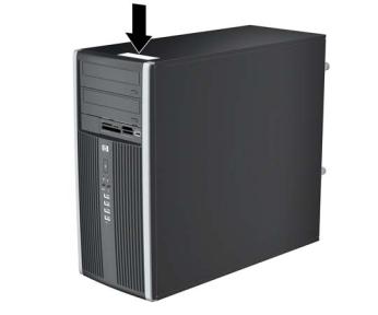
The HP Compaq Microtower features may vary depending on the model. For a complete listing of the hardware and software installed in the computer, run the diagnostic utility (included on some computer models only). Instructions for using the utility are provided in the Troubleshooting Guide.
Figure 1-1 Microtower Configuration
Microtower Chassis |
1 |

Front Panel Components
Drive configuration may vary by model.
Table 1-1 Front Panel Components
1 |
5.25-inch Optical Drives1 |
6 |
Optical Drive Eject Buttons |
2 |
Optical Drive Activity Lights |
7 |
3.5-inch Media Card Reader (optional)2 |
3 |
Hard Drive Activity Light |
8 |
Dual-State Power Button |
|
|
|
|
4 |
Microphone/Headphone Connector |
9 |
Power On Light |
|
|
|
|
5 |
USB (Universal Serial Bus) 2.0 Ports |
10 |
Headphone Connector |
NOTE: When a device is plugged into the Microphone/Headphone Connector, a dialog box will pop up asking if you want to use the connector for a microphone line Line-In device or a headphone. You can reconfigure the connector at any time by double-clicking the Realtek HD Audio Manager icon in the Windows taskbar.
NOTE: The Power On Light is normally green when the power is on. If it is flashing red, there is a problem with the computer and it is displaying a diagnostic code. Refer to the Troubleshooting Guide to interpret the code.
1Some models have bezel blanks covering one or both of the 5.25-inch drive bays.
2Some models have a bezel blank covering the 3.5-inch drive bay.
2 Chapter 1 Product Features

Media Card Reader Components
The media card reader is an optional device available on some models only. Refer to the following illustration and table to identify the media card reader components.
Figure 1-2 Media Card Reader Components
Table 1-2 Media Card Reader Components
No. |
Slot |
Media |
|
|
|
|
|
|
|
1 |
xD |
● |
xD-Picture Card (xD) |
|
|
|
|
|
|
2 |
MicroSD |
● |
MicroSD (T-Flash) |
● MicroSDHC |
3Media Card Reader Activity Light
4 |
SD/MMC+/miniSD |
● |
Secure Digital (SD) |
● |
MiniSDHC |
● |
MultiMediaCard 4.0 |
|
|
● |
Secure Digital High |
● |
MultiMediaCard |
|
(MMC Plus) |
|
|
|
Reduced Size |
||||
|
|
|
Capacity (SDHC) |
|
(MMC) |
● |
|
|
|
● |
MiniSD |
● |
Reduced Size |
|
MultiMediaCard 4.0 |
|
|
|
(MMC Mobile) |
||||
|
|
|
|
|
MultiMediaCard (RS |
|
MMC Micro (adapter |
|
|
|
|
|
MMC) |
● |
|
|
|
|
|
|
|
|
required) |
|
|
|
|
|
|
|
|
5 |
USB |
● |
USB (Universal Serial |
|
|
|
|
|
|
|
Bus) Port |
|
|
|
|
|
|
|
|
|
|
|
|
6 |
CompactFlash I/II |
● |
CompactFlash Card |
● |
CompactFlash Card |
● |
MicroDrive |
|
|
|
Type 1 |
|
Type 2 |
|
|
|
|
|
|
|
|
|
|
7 |
MS PRO/MS PRO DUO |
● |
Memory Stick (MS) |
● |
Memory Stick Select |
● |
Memory Stick PRO |
|
|
● |
MagicGate Memory |
● |
Memory Stick Duo |
|
Duo (MS PRO Duo) |
|
|
|
Memory Stick PRO- |
||||
|
|
|
Stick (MG) |
|
(MS Duo) |
● |
|
|
|
● |
MagicGate Memory |
● |
Memory Stick PRO |
|
HG Duo |
|
|
|
Memory Stick Micro |
||||
|
|
|
Duo |
|
(MS PRO) |
● |
|
|
|
|
|
|
|
|
(M2) (adapter |
|
|
|
|
|
|
|
required) |
|
|
|
|
|
|
|
|
8 |
1394 |
● |
1394 Port (available |
|
|
|
|
|
|
|
on select models only) |
|
|
|
|
|
|
|
|
|
|
|
|
Microtower Chassis |
3 |

Rear Panel Components
Table 1-3 Rear Panel Components
1 |
Power Cord Connector |
6 |
Line-Out Connector for powered audio |
|
|
|
devices (green) |
|
|
|
|
2 |
Line-In Audio Connector (blue) |
7 |
PS/2 Keyboard Connector (purple) |
|
|
|
|
3 |
PS/2 Mouse Connector (green) |
8 |
VGA Monitor Connector |
|
|
|
|
4 |
Serial Connector |
9 |
DisplayPort Monitor Connector |
|
|
|
|
5 |
RJ-45 Network Connector |
10 |
Universal Serial Bus (USB) |
NOTE: Arrangement and number of connectors may vary by model.
An optional second serial port and an optional parallel port are available from HP.
When a device is plugged into the blue Line-In Audio Connector, a dialog box will pop up asking if you want to use the connector for a line-in device or a microphone. You can reconfigure the connector at any time by double-clicking the Realtek HD Audio Manager icon in the Windows taskbar.
The monitor connectors on the system board are inactive when a graphics card is installed in the computer.
If a graphics card is installed into the PCI, PCI Express x1, or the PCI Express x16 slot, the connectors on the graphics card and the system board may be used at the same time. The connectors on the system board may be used at the same time only if an ATI graphics card is installed in the PCI Express x16 connector. Some settings may need to be changed in Computer Setup to use both connectors. For information about setting the boot VGA controller, refer to the Computer Setup (F10) Utility Guide.
4 Chapter 1 Product Features
Serial Number Location
Each computer has a unique serial number and product ID number that are located on the top cover of the computer. Keep these numbers available for use when contacting customer service for assistance.
Figure 1-3 Serial Number and Product ID Location
Microtower Chassis |
5 |

Small Form Factor
Standard Configuration Features
The HP Compaq Small Form Factor features may vary depending on the model. For a complete listing of the hardware and software installed in the computer, run the diagnostic utility (included on some computer models only). Instructions for using the utility are provided in the Troubleshooting Guide.
 NOTE: The Small Form Factor computer can also be used in a tower orientation. For more information, see Using the Small Form Factor Computer in a Tower Orientationon page 173 in this guide.
Figure 1-4 Small Form Factor Configuration
6 Chapter 1 Product Features

Front Panel Components
Drive configuration may vary by model.
Figure 1-5 Front Panel Components
Table 1-4 Front Panel Components
1 |
5.25-inch Optical Drive1 |
6 |
USB (Universal Serial Bus) Ports |
2 |
Optical Drive Activity Light |
7 |
Microphone/Headphone Connector |
|
|
|
|
3 |
Optical Drive Eject Button |
8 |
3.5-inch Media Card Reader (optional)2 |
4 |
Dual-State Power Button |
9 |
Hard Drive Activity Light |
|
|
|
|
5 |
Power On Light |
10 |
Headphone Connector |
NOTE: When a device is plugged into the Microphone/Headphone Connector, a dialog box will pop up asking if you want to use the connector for a microphone line Line-In device or a headphone. You can reconfigure the connector at any time by double-clicking the Realtek HD Audio Manager icon in the Windows taskbar.
NOTE: The Power On Light is normally green when the power is on. If it is flashing red, there is a problem with the computer and it is displaying a diagnostic code. Refer to the Troubleshooting Guide to interpret the code.
1Some models are configured with a 5.25-inch bezel blank covering this bay.
2Some models are configured with a 3.5-inch bezel blank covering this bay.
Small Form Factor |
7 |

Media Card Reader Components
The media card reader is an optional device available on some models only. Refer to the following illustration and table to identify the media card reader components.
Figure 1-6 Media Card Reader Components
Table 1-5 Media Card Reader Components
No. |
Slot |
Media |
|
|
|
|
|
|
|
1 |
xD |
● |
xD-Picture Card (xD) |
|
|
|
|
|
|
2 |
MicroSD |
● |
MicroSD (T-Flash) |
● MicroSDHC |
3Media Card Reader Activity Light
4 |
SD/MMC+/miniSD |
● |
Secure Digital (SD) |
● |
MiniSDHC |
● |
MultiMediaCard 4.0 |
|
|
● |
Secure Digital High |
● |
MultiMediaCard |
|
(MMC Plus) |
|
|
|
Reduced Size |
||||
|
|
|
Capacity (SDHC) |
|
(MMC) |
● |
|
|
|
● |
MiniSD |
● |
Reduced Size |
|
MultiMediaCard 4.0 |
|
|
|
(MMC Mobile) |
||||
|
|
|
|
|
MultiMediaCard (RS |
|
MMC Micro (adapter |
|
|
|
|
|
MMC) |
● |
|
|
|
|
|
|
|
|
required) |
|
|
|
|
|
|
|
|
5 |
USB |
● |
USB (Universal Serial |
|
|
|
|
|
|
|
Bus) Port |
|
|
|
|
|
|
|
|
|
|
|
|
6 |
CompactFlash I/II |
● |
CompactFlash Card |
● |
CompactFlash Card |
● |
MicroDrive |
|
|
|
Type 1 |
|
Type 2 |
|
|
|
|
|
|
|
|
|
|
7 |
MS PRO/MS PRO DUO |
● |
Memory Stick (MS) |
● |
Memory Stick Select |
● |
Memory Stick PRO |
|
|
● |
MagicGate Memory |
● |
Memory Stick Duo |
|
Duo (MS PRO Duo) |
|
|
|
Memory Stick PRO- |
||||
|
|
|
Stick (MG) |
|
(MS Duo) |
● |
|
|
|
● |
MagicGate Memory |
● |
Memory Stick PRO |
|
HG Duo |
|
|
|
Memory Stick Micro |
||||
|
|
|
Duo |
|
(MS PRO) |
● |
|
|
|
|
|
|
|
|
(M2) (adapter |
|
|
|
|
|
|
|
required) |
|
|
|
|
|
|
|
|
8 |
1394 |
● |
1394 Port (available |
|
|
|
|
|
|
|
on select models only) |
|
|
|
|
|
|
|
|
|
|
|
|
8 Chapter 1 Product Features

Rear Panel Components
Figure 1-7 Rear Panel Components
Table 1-6 Rear Panel Components
1 |
RJ-45 Network Connector |
6 |
DisplayPort Monitor Connector |
|
|
|
|
2 |
Serial Connector |
7 |
VGA Monitor Connector |
|
|
|
|
3 |
PS/2 Mouse Connector (green) |
8 |
PS/2 Keyboard Connector (purple) |
|
|
|
|
4 |
Power Cord Connector |
9 |
Line-Out Connector for powered audio |
|
|
|
devices (green) |
|
|
|
|
5 |
Universal Serial Bus (USB) |
10 |
Line-In Audio Connector (blue) |
NOTE: Arrangement and number of connectors may vary by model.
An optional second serial port and an optional parallel port are available from HP.
When a device is plugged into the blue Line-In Audio Connector, a dialog box will pop up asking if you want to use the connector for a line-in device or a microphone. You can reconfigure the connector at any time by double-clicking the Realtek HD Audio Manager icon in the Windows taskbar.
The monitor connectors on the system board are inactive when a graphics card is installed in the computer.
If a graphics card is installed into the PCI, PCI Express x1, or the PCI Express x16 slot, the connectors on the graphics card and the system board may be used at the same time. The connectors on the system board may be used at the same time only if an ATI graphics card is installed in the PCI Express x16 connector. Some settings may need to be changed in Computer Setup to use both connectors. For information about setting the boot VGA controller, refer to the Computer Setup (F10) Utility Guide.
Small Form Factor |
9 |

Serial Number Location
Each computer has a unique serial number and product ID number in the location shown below. Keep these numbers available for use when contacting customer service for assistance.
Figure 1-8 Serial Number and Product ID Location
10 Chapter 1 Product Features

2 Installing and Customizing the Software
If your computer was not shipped with a Microsoft operating system, some portions of this documentation do not apply. Additional information is available in online help after you install the operating system.
 NOTE: If the computer was shipped with Windows Vista or Windows 7 loaded, you will be prompted to register the computer with HP Total Care before installing the operating system. You will see a brief movie followed by an online registration form. Fill out the form, click the Begin button, and follow the instructions on the screen.
 CAUTION: Do not add optional hardware or third-party devices to the computer until the operating system is successfully installed. Doing so may cause errors and prevent the operating system from installing properly.
 NOTE: Be sure there is a 10.2-cm (4-inch) clearance at the back of the unit and above the monitor to permit the required airflow.
11

Installing the Operating System
The first time you turn on the computer, the operating system is installed automatically. This process takes about 5 to 10 minutes, depending on which operating system is being installed. Carefully read and follow the instructions on the screen to complete the installation.
 CAUTION: Once the automatic installation has begun, DO NOT TURN OFF THE COMPUTER UNTIL THE PROCESS IS COMPLETE. Turning off the computer during the installation process may damage the software that runs the computer or prevent its proper installation.
 NOTE: If the computer shipped with more than one operating system language on the hard drive, the installation process could take up to 60 minutes.
If your computer was not shipped with a Microsoft operating system, some portions of this documentation do not apply. Additional information is available in online help after you install the operating system.
Downloading Microsoft Windows Updates
1.To set up your Internet connection, click Start > Internet Explorer and follow the instructions on the screen.
2.Once an Internet connection has been established, click the Start button.
3.Select the All Programs menu.
4.Click on the Windows Update link.
In Windows Vista and Windows 7, the Windows Update screen appears. Click view available updates and make sure all critical updates are selected. Click the Install button and follow the instructions on the screen.
In Windows XP, you will be directed to the Microsoft Windows Update Web site. If you see one or more pop-up windows that ask you to install a program from http://www.microsoft.com, click Yes to install the program. Follow the instructions on the Microsoft Web site to scan for updates and install critical updates and service packs.
It is recommended that you install all of the critical updates and service packs.
5.After the updates have been installed, Windows will prompt you to reboot the machine. Be sure to save any files or documents that you may have open before rebooting. Then select Yes to reboot the machine.
Installing or Upgrading Device Drivers (Windows systems)
When installing optional hardware devices after the operating system installation is complete, you must also install the drivers for each of the devices.
If prompted for the i386 directory, replace the path specification with C:\i386, or use the Browse button in the dialog box to locate the i386 folder. This action points the operating system to the appropriate drivers.
Obtain the latest support software, including support software for the operating system from http://www.hp.com/support. Select your country and language, select Download drivers and software (and firmware), enter the model number of the computer, and press Enter.
12 Chapter 2 Installing and Customizing the Software
Accessing Disk Image (ISO) Files
There are disk image files (ISO files) included on your PC that contain the installation software for additional software. These CD image files are located in the folder C:\SWSetup\ISOs. Each .iso file can be burned to CD media to create an installation CD. It is recommended that these disks be created and the software installed in order to get the most from your PC. The software and image file names are:
●Corel WinDVD SD and BD – installation software for WinDVD – used to play DVD movies
●HP Insight Diagnostics OR Vision Diagnostics – software to perform diagnostic activities on your PC
Protecting the Software
To protect the software from loss or damage, keep a backup copy of all system software, applications, and related files stored on the hard drive. Refer to the operating system or backup utility documentation for instructions on making backup copies of your data files.
Accessing Disk Image (ISO) Files 13

3 Computer Setup (F10) Utility
Computer Setup (F10) Utilities
Use Computer Setup (F10) Utility to do the following:
●Change system default settings.
●Set the system date and time.
●Set, view, change, or verify the system configuration, including settings for processor, graphics, memory, audio, storage, communications, and input devices.
●Modify the boot order of bootable devices such as hard drives, optical drives, or USB flash media devices.
●Enable Quick Boot, which is faster than Full Boot but does not run all of the diagnostic tests run during a Full Boot. You can set the system to:
◦always Quick Boot (default);
◦periodically Full Boot (from every 1 to 30 days); or
◦always Full Boot.
●Select Post Messages Enabled or Disabled to change the display status of Power-On Self-Test (POST) messages. Post Messages Disabled suppresses most POST messages, such as memory count, product name, and other non-error text messages. If a POST error occurs, the error is displayed regardless of the mode selected. To manually switch to Post Messages Enabled during POST, press any key (except F1 through F12).
●Establish an Ownership Tag, the text of which is displayed each time the system is turned on or restarted.
●Enter the Asset Tag or property identification number assigned by the company to this computer.
●Enable the power-on password prompt during system restarts (warm boots) as well as during power-on.
●Establish a setup password that controls access to Computer Setup (F10) Utility and the settings described in this section.
●Secure integrated I/O functionality, including the serial, USB, or parallel ports, audio, or embedded NIC, so that they cannot be used until they are unsecured.
●Enable or disable removable media boot ability.
●Solve system configuration errors detected but not automatically fixed during the Power-On SelfTest (POST).
14 Chapter 3 Computer Setup (F10) Utility

●Replicate the system setup by saving system configuration information on USB flash media device or other storage media emulating a diskette and restoring it on one or more computers.
●Execute self-tests on a specified ATA hard drive (when supported by drive).
●Enable or disable DriveLock security (when supported by drive).
Using Computer Setup (F10) Utilities
Computer Setup can be accessed only by turning the computer on or restarting the system. To access the Computer Setup Utilities menu, complete the following steps:
1.Turn on or restart the computer.
2.As soon as the computer is turned on, press F10 when the monitor light turns green to enter Computer Setup. Press Enter to bypass the title screen, if necessary.
 NOTE: If you do not press F10 at the appropriate time, you must restart the computer and again press F10 when the monitor light turns green to access the utility.
3.Select your language from the list and press Enter.
4.A choice of five headings appears in the Computer Setup Utilities menu: File, Storage, Security, Power and Advanced.
5.Use the arrow (left and right) keys to select the appropriate heading. Use the arrow (up and down) keys to select the option you want, then press Enter. To return to the Computer Setup Utilities menu, press Esc.
6.To apply and save changes, select File > Save Changes and Exit.
●If you have made changes that you do not want applied, select Ignore Changes and Exit.
●To reset to factory settings or previously saved default settings (some models), select Apply Defaults and Exit.
 CAUTION: Do NOT turn the computer power OFF while the ROM is saving the Computer Setup (F10) changes because the CMOS could become corrupted. It is safe to turn off the computer only after exiting the F10 Setup screen.
Table 3-1 Computer Setup (F10) Utility
Heading |
Table |
|
|
|
|
File |
Table 3-2 Computer Setup—File on page 16 |
|
|
|
|
Storage |
Table 3-3 Computer Setup—Storage on page 17 |
|
|
|
|
Security |
Table 3-4 Computer Setup—Security on page 20 |
|
|
|
|
Power |
Table 3-5 |
Computer Setup—Power on page 23 |
|
|
|
Advanced |
Table 3-6 |
Computer Setup—Advanced (for advanced users) |
|
on page 24 |
|
|
|
|
Computer Setup (F10) Utilities 15

Computer Setup—File
 NOTE: Support for specific Computer Setup options may vary depending on the hardware configuration.
Table 3-2 Computer Setup—File
Option |
Description |
|
|
|
|
System Information |
Lists: |
|
|
● |
Product name |
|
● SKU number (some models) |
|
|
● |
Processor type/speed/stepping |
|
● |
Cache size (L1/L2/L3) |
|
● Installed memory size/speed, number of channels (single or dual) (if applicable) |
|
|
● Integrated MAC address for embedded, enabled NIC (if applicable) |
|
|
● System BIOS (includes family name and version) |
|
|
● |
Chassis serial number |
|
● |
Asset tracking number |
|
● |
Management Mode |
|
|
|
About |
Displays copyright notice. |
|
|
|
|
Set Time and Date |
Allows you to set system time and date. |
|
|
|
|
Flash System ROM |
Allows you to update the system ROM with a BIOS image file located on a USB flash media device |
|
|
or CD-ROM. |
|
|
|
|
Replicated Setup |
Save to Removable Media |
|
|
Saves system configuration, including CMOS, to a USB flash media device or a diskette-like device |
|
|
(a storage device set to emulate a diskette drive). |
|
|
Restore from Removable Media |
|
|
Restores system configuration from a USB flash media device or a diskette-like device. |
|
|
|
|
Default Setup |
Save Current Settings as Default |
|
|
Saves the current system configuration settings as the default. |
|
|
Restore Factory Settings as Default |
|
|
Restores the factory system configuration settings as the default. |
|
|
|
|
Apply Defaults and |
Applies the currently selected default settings and clears any established passwords. |
|
Exit |
|
|
|
|
|
Ignore Changes |
Exits Computer Setup without applying or saving any changes. |
|
and Exit |
|
|
Save Changes and Exit Saves changes to system configuration or default settings and exits Computer Setup.
16 Chapter 3 Computer Setup (F10) Utility

Computer Setup—Storage
 NOTE: Support for specific Computer Setup options may vary depending on the hardware configuration.
Table 3-3 Computer Setup—Storage
Option |
Description |
|
|
Device Configuration Lists all installed BIOS-controlled storage devices.
When a device is selected, detailed information and options are displayed. The following options may be presented.
Emulation Type
Allows you to select a drive emulation type for a certain storage device. (For example, a Zip drive can be made bootable by selecting diskette emulation.)
Drive Emulation Type Options
ATAPI Zip drive:
●None (treated as Other).
●Diskette (treated as diskette drive). CD-ROM: No emulation options available. ATAPI LS-120:
●None (treated as Other).
●Diskette (treated as diskette drive). Hard Disk
●None (prevents BIOS data accesses and disables it as a boot device).
●Hard Disk (treated as hard disk).
Translation Mode (ATA disks only)
Lets you select the translation mode to be used for the device. This enables the BIOS to access disks partitioned and formatted on other systems and may be necessary for users of older versions of UNIX (e.g., SCO UNIX version 3.2). Options are Automatic, Bit-Shift, LBA Assisted, User, and Off.
CAUTION: Ordinarily, the translation mode selected automatically by the BIOS should not be changed. If the selected translation mode is not compatible with the translation mode that was active when the disk was partitioned and formatted, the data on the disk will be inaccessible.
Translation Parameters (ATA disks only)
NOTE: This feature appears only when User translation mode is selected.
Allows you to specify the parameters (logical cylinders, heads, and sectors per track) used by the BIOS to translate disk I/O requests (from the operating system or an application) into terms the hard drive can accept. Logical cylinders may not exceed 1024. The number of heads may not exceed 256. The number of sectors per track may not exceed 63. These fields are only visible and changeable when the drive translation mode is set to User.
SATA Default Values
Allows you to specify the default values for the Translation Mode for ATA devices.
Computer Setup (F10) Utilities 17

Table 3-3 Computer Setup—Storage (continued)
Option |
Description |
|
|
Storage Options |
Removable Media Boot |
|
Enables/disables ability to boot the system from removable media. |
|
eSATA Port |
|
Allows you to enable eSATA support. This causes one of the SATA connectors to become eSATA |
|
capable. |
|
Max eSATA Speed |
|
Allows you to choose 1.5 Gbps or 3.0 Gbps as the maximum eSATA speed. By default, the speed |
|
is limited to 1.5 Gbps for maximum reliability. |
|
CAUTION: Consult your eSATA drive and cable manufacturer before enabling 3.0 Gbps speed. |
|
Some drive and cable combinations may not run reliably at 3.0 Gbps. |
|
SATA Emulation |
|
Allows you to choose how the SATA controller and devices are accessed by the operating system. |
|
There are up to four supported options: Legacy Mode IDE, Native Mode IDE, AHCI, and RAID. |
|
Legacy Mode IDE - This is the most backwards-compatible setting of these options. Operating |
|
systems usually do not require additional driver support in IDE mode. |
|
Native Mode IDE - Allows software to communicate with the SATA controller like a traditional PATA |
|
controller using natively assigned PCI resources. The difference between it and Legacy Mode IDE |
|
is that legacy mode uses the legacy resources for PATA controllers (IRQs 14 and 15, I/Os |
|
1F0h-1F7h, 3F6h, 170h-177h, etc.). |
|
AHCI (default option) - Allows operating systems with AHCI device drivers loaded to take advantage |
|
of more advanced features of the SATA controller. |
|
RAID - Allows DOS and boot access to RAID volumes. Use this mode with the RAID device driver |
|
loaded in the operating system to take advantage of RAID features. |
|
NOTE: The RAID/AHCI device driver must be installed prior to attempting to boot from a RAID/ |
|
AHCI volume. If you attempt to boot from a RAID/AHCI volume without the required device driver |
|
installed, the system will crash (blue screen). RAID volumes may become corrupted if they are |
|
booted to after disabling RAID. |
|
For more information on RAID, go to http://www.hp.com/support. Select your country and language, |
|
select See support and troubleshooting information, enter the model number of the computer, |
|
and press Enter. In the Resources category, click Manuals (guides, supplements, addendums, |
|
etc). Under Quick jump to manuals by category, click White papers. |
|
|
18 Chapter 3 Computer Setup (F10) Utility
Loading...