


 Loading...
HP R/T3000 G2 UPS
User Guide
Abstract
This document includes installation, configuration, and operation information for the HP R/T3000 G2 UPS. This document is for the person who installs and maintains power products. HP assumes you are qualified in the servicing of high-voltage equipment and trained in recognizing hazards in products with hazardous energy levels.
Part Number: 651176-002
June 2012
Edition: 2
© Copyright 2011, 2012 Hewlett-Packard Development Company, L.P.
The information contained herein is subject to change without notice. The only warranties for HP products and services are set forth in the express warranty statements accompanying such products and services. Nothing herein should be construed as constituting an additional warranty. HP shall not be liable for technical or editorial errors or omissions contained herein.
Microsoft®, Windows®, Windows Server®, and Windows Vista® are U.S. registered trademarks of Microsoft Corporation. Bluetooth® is a trademark owned by its proprietor and used by Hewlett-Packard Company under license.

Contents |
|
Component identification............................................................................................................... |
7 |
UPS R/T3000 G2 overview........................................................................................................................ |
7 |
UPS front panel......................................................................................................................................... |
7 |
UPS front panel controls ............................................................................................................................. |
8 |
UPS front panel LED indicators .................................................................................................................... |
8 |
HP UPS R/T3000 models ........................................................................................................................... |
9 |
R/T3000 NA and R/T3000j JPN rear panel ................................................................................................ |
9 |
R/T3000h NA and R/T3000h JPN rear panel............................................................................................ |
10 |
R/T3000 INT rear panel .......................................................................................................................... |
11 |
REPO port .............................................................................................................................................. |
11 |
ERM rear panel....................................................................................................................................... |
12 |
Installation ................................................................................................................................. |
13 |
Precautions............................................................................................................................................. |
13 |
Preparing to install the hardware............................................................................................................... |
13 |
Tools and materials........................................................................................................................ |
13 |
Selecting a site.............................................................................................................................. |
14 |
Readying the equipment ................................................................................................................. |
14 |
Installing the mounting rails ...................................................................................................................... |
14 |
Installing the UPS in a rack ....................................................................................................................... |
17 |
Connecting the battery leads........................................................................................................... |
18 |
Attaching the UPS front bezel.......................................................................................................... |
20 |
Connecting the host computer ......................................................................................................... |
20 |
Connecting the REPO port .............................................................................................................. |
21 |
Connecting the ground bonding cable ............................................................................................. |
23 |
Connecting the UPS to utility power ................................................................................................. |
24 |
Connecting devices to the UPS ........................................................................................................ |
24 |
Connecting the UPS cord retention clips ........................................................................................... |
25 |
Charging the UPS batteries ............................................................................................................. |
25 |
Starting power to the load .............................................................................................................. |
26 |
Installing the ERM in a rack ...................................................................................................................... |
26 |
Connecting the battery leads........................................................................................................... |
27 |
Attaching the ERM front bezel ......................................................................................................... |
28 |
Connecting the ERM to the UPS ....................................................................................................... |
29 |
Switching on the ERM circuit breaker ............................................................................................... |
30 |
Charging the ERM batteries ............................................................................................................ |
30 |
Installing the optional UPS Network Module ............................................................................................... |
31 |
Connecting the UPS Network Module .............................................................................................. |
32 |
Installing the UPS as a tower..................................................................................................................... |
32 |
Connecting the battery leads........................................................................................................... |
33 |
Rotating the logo badge................................................................................................................. |
33 |
Attaching the UPS front bezel.......................................................................................................... |
34 |
Attaching the tower conversion stands.............................................................................................. |
34 |
Continuing the installation .............................................................................................................. |
34 |
Installing the ERM as a tower .................................................................................................................... |
35 |
Rotating the logo badge................................................................................................................. |
35 |
Attaching the ERM front bezel ......................................................................................................... |
35 |
Contents |
3 |
Attaching the tower conversion stands.............................................................................................. |
35 |
Continuing the ERM installation ....................................................................................................... |
37 |
Installing the extension bars (if included) .................................................................................................... |
38 |
Connecting and securing the power cords .................................................................................................. |
39 |
UPS operations........................................................................................................................... |
40 |
Modes of operation ................................................................................................................................. |
40 |
Standby mode .............................................................................................................................. |
40 |
Operate mode .............................................................................................................................. |
40 |
Configure mode ............................................................................................................................ |
41 |
Battery mode ................................................................................................................................ |
41 |
Auto-Bypass mode ......................................................................................................................... |
41 |
Operating the UPS front panel controls ...................................................................................................... |
41 |
Configuring the UPS ................................................................................................................................ |
42 |
Initiating a self-test ................................................................................................................................... |
43 |
Silencing an audible alarm....................................................................................................................... |
44 |
Verifying the REPO port connection ........................................................................................................... |
44 |
Powering down the UPS........................................................................................................................... |
44 |
Maintenance .............................................................................................................................. |
45 |
Removing the UPS front bezel ................................................................................................................... |
45 |
Removing the ERM front bezel................................................................................................................... |
45 |
Replacing the batteries............................................................................................................................. |
45 |
Important battery safety information ................................................................................................. |
46 |
Battery care and storage guidelines ................................................................................................. |
46 |
Determining when to replace batteries.............................................................................................. |
46 |
Obtaining new batteries................................................................................................................. |
47 |
UPS battery replacement procedure ................................................................................................. |
47 |
Testing the new battery module ....................................................................................................... |
48 |
Replacing the UPS ................................................................................................................................... |
49 |
Replacing the ERM .................................................................................................................................. |
49 |
Replacing the UPS option card.................................................................................................................. |
49 |
Updating the UPS firmware ...................................................................................................................... |
50 |
Configuring a USB to serial converter............................................................................................... |
50 |
Reassigning the USB COM ports ..................................................................................................... |
51 |
Power management .................................................................................................................... |
53 |
Power Protector software .......................................................................................................................... |
53 |
Troubleshooting .......................................................................................................................... |
55 |
LED troubleshooting ................................................................................................................................. |
55 |
UPS is in Auto-Bypass mode...................................................................................................................... |
56 |
UPS is in Converter Off mode ................................................................................................................... |
57 |
General alarm condition .......................................................................................................................... |
57 |
Bypass is out of range.............................................................................................................................. |
58 |
Battery condition ..................................................................................................................................... |
58 |
UPS is on battery..................................................................................................................................... |
58 |
Input voltage is out of range ..................................................................................................................... |
58 |
Overtemperature condition ....................................................................................................................... |
59 |
Internal UPS fault condition....................................................................................................................... |
59 |
REPO condition....................................................................................................................................... |
59 |
Site wiring condition................................................................................................................................ |
59 |
Overload condition ................................................................................................................................. |
59 |
Checksum failure error ............................................................................................................................. |
60 |
UPS does not start ................................................................................................................................... |
60 |
Contents |
4 |
Low battery shutdowns ............................................................................................................................. |
60 |
UPS does not provide the expected backup time ......................................................................................... |
60 |
UPS frequently switches between utility and battery power............................................................................ |
60 |
Specifications............................................................................................................................. |
61 |
UPS physical specifications....................................................................................................................... |
61 |
ERM physical specifications ...................................................................................................................... |
61 |
UPS input specifications ........................................................................................................................... |
61 |
UPS output specifications.......................................................................................................................... |
61 |
Power protection specifications ....................................................................................................... |
62 |
Output tolerance specifications........................................................................................................ |
62 |
Output feature specifications ........................................................................................................... |
62 |
Battery specifications ............................................................................................................................... |
62 |
High-voltage UPS battery runtimes ............................................................................................................. |
63 |
Low-voltage UPS battery runtimes .............................................................................................................. |
63 |
Environmental specifications ..................................................................................................................... |
63 |
REPO port specifications .......................................................................................................................... |
63 |
Spares....................................................................................................................................... |
64 |
Ordering spares...................................................................................................................................... |
64 |
UPS spare parts list.................................................................................................................................. |
64 |
ERM spare parts list ................................................................................................................................. |
65 |
Hardware options ................................................................................................................................... |
65 |
Support and other resources ........................................................................................................ |
66 |
Before you contact HP.............................................................................................................................. |
66 |
HP contact information............................................................................................................................. |
66 |
Warranty information.................................................................................................................. |
67 |
Limited warranty ..................................................................................................................................... |
67 |
$250,000 Computer Load Protection Guarantee......................................................................................... |
67 |
Pre-Failure Battery Warranty ..................................................................................................................... |
67 |
Recommended duration of use .................................................................................................................. |
68 |
Regulatory compliance notices ..................................................................................................... |
69 |
Regulatory compliance identification numbers ............................................................................................. |
69 |
Federal Communications Commission notice............................................................................................... |
69 |
FCC rating label............................................................................................................................ |
69 |
FCC Notice, Class A Equipment ...................................................................................................... |
69 |
FCC Notice, Class B Equipment ...................................................................................................... |
69 |
Declaration of conformity for products marked with the FCC logo, United States only....................................... |
70 |
Modifications.......................................................................................................................................... |
70 |
Cables................................................................................................................................................... |
70 |
Canadian notice (Avis Canadien).............................................................................................................. |
70 |
European Union regulatory notice ............................................................................................................. |
71 |
Disposal of waste equipment by users in private households in the European Union ......................................... |
71 |
Japanese notice ...................................................................................................................................... |
72 |
BSMI notice ............................................................................................................................................ |
72 |
Korean notice ......................................................................................................................................... |
72 |
Chinese notice ........................................................................................................................................ |
73 |
Battery replacement notice........................................................................................................................ |
73 |
Taiwan battery recycling notice................................................................................................................. |
73 |
Power cord statement for Japan................................................................................................................. |
74 |
Electrostatic discharge................................................................................................................. |
75 |
Contents |
5 |
Preventing electrostatic discharge .............................................................................................................. |
75 |
Grounding methods to prevent electrostatic discharge.................................................................................. |
75 |
Acronyms and abbreviations........................................................................................................ |
76 |
Documentation feedback ............................................................................................................. |
77 |
Index......................................................................................................................................... |
78 |
Contents 6

Component identification
UPS R/T3000 G2 overview
The HP UPS R/T3000 G2 features a 2U rack-mount with convertible tower design and offers power protection for loads up to a maximum of 3300 VA/3000 W (these numbers might vary by model).
To benefit from the latest product enhancements, update to the latest versions of UPS firmware and software.
NOTE: To download the latest versions of UPS firmware and software, see the HP website (http://www.hp.com/go/rackandpower).
UPS front panel
Item |
Description |
|
|
1 |
Battery compartment |
2 |
Front panel display |
|
|
Component identification 7

UPS front panel controls
Item |
Description |
Function |
|
|
|
1 |
Test/Alarm Reset button |
Silences UPS alarms ("Silencing an audible |
|
|
alarm" on page 44) |
2 |
Off button |
Places the UPS in Standby mode (on page |
|
|
40) |
|
|
|
3 |
On button |
Powers up the UPS ("Starting power to the |
|
|
load" on page 26) |
|
|
|
4 |
Battery Start button |
Starts the UPS on battery power when |
|
|
pressed with the On button |
UPS front panel LED indicators
Component identification 8
The front panel is shown with the bezel removed.
Item |
LED description |
Load level |
|
|
|
1 |
Self Test |
On—The load level is greater than 10%. |
2 |
Battery Fault |
On—The load level is greater than 25%. |
3 |
Site Wiring Fault |
On—The load level is greater than 50%. |
4 |
Overtemperature |
On—The load level is greater than 75%. |
5 |
Overload |
On—The load level is greater than 100%. |
6 |
On Bypass |
|
7 |
On Battery |
|
8 |
Utility |
|
For more information, see "LED troubleshooting (on page 55)" .
HP UPS R/T3000 models
UPS model |
Description |
|
|
|
|
R/T3000 NA and R/T3000j JPN |
• |
Domestic/Japanese |
|
• |
Low-voltage |
|
• Nondetachable NEMA L5-30 plug |
|
|
|
|
R/T3000h NA and R/T3000h |
• |
Domestic |
JPN |
• |
High-voltage |
|
• Nondetachable NEMA L6-20 plug |
|
|
|
|
R/T3000 INT |
• |
International |
|
• |
High-voltage |
|
• Detachable country-specific plug |
|
|
|
|
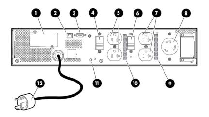
R/T3000 NA and R/T3000j JPN rear panel
Item |
Description |
|
|
1 |
UPS option card |
2 |
USB communications port |
3 |
Serial communications port |
Component identification 9
Item |
Description |
|
|
4 |
Load segment circuit breaker |
5 |
Load segment 1 (two NEMA 5-20R T-Slot receptacles) |
|
|
6 |
Load segment circuit breaker |
7 |
Load segment 2 (two NEMA 5-20R T-Slot receptacles) |
8 |
PDU output (NEMA L5-30R) receptacle (load segment 1) |
|
|
9 |
Cord retention clip attachment location |
10 |
Cord retention clip attachment location |
11 |
Ground bonding screw |
12 |
Power cord with L5-30 plug |
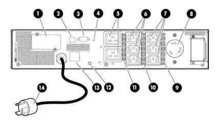
R/T3000h NA and R/T3000h JPN rear panel
Item |
Description |
|
|
1 |
UPS option card |
2 |
USB communications port |
3 |
Serial communications port |
4 |
Ground bonding screw |
5 |
Load segment 1 and 2 (one IEC-320-C19 receptacle) |
6 |
Load segment 1 (three IEC-320-C13 receptacles) |
7 |
Load segment 2 (three IEC-320-C13 receptacles) |
8 |
PDU output (L6-20) receptacle (load segment 1) |
9 |
Cord retention clip attachment location |
10 |
Cord retention clip attachment location |
11 |
Cord retention clip attachment location |
12 |
Ground bonding screw |
13 |
REPO port |
14 |
Power cord with L6-20 plug |
Component identification 10
R/T3000 INT rear panel
Item |
Description |
|
|
1 |
UPS option card |
2 |
USB communications port |
3 |
Serial communications port |
4 |
Ground bonding screw |
5 |
Load segment 1 and 2 (one IEC-320-C19 receptacle) |
6 |
Load segment 1 (three IEC-320-C13 receptacles) |
7 |
Load segment 2 (three IEC-320-C13 receptacles) |
8 |
Cord retention clip attachment location |
9 |
Cord retention clip attachment location |
10 |
Cord retention clip attachment location |
11 |
Ground bonding screw |
12 |
REPO port |
13 |
Input power receptacle (IEC-320-C19) for country-specific plug |
|
attachment |
|
|
REPO port
The UPS includes an isolated REPO port. When properly wired, the REPO feature enables the power at the UPS output receptacles to be switched off from a remote location. To use this feature, the REPO port must be connected to a remote, normally-open switch (not supplied). The REPO switch is used in conjunction with a main disconnect device that removes the AC source from the input of the UPS. When the switch is closed:
•The REPO feature immediately powers down protected devices and does not utilize the orderly shutdown procedure initiated by power management software.
•The REPO feature shuts down UPS units operating under either utility or battery power.
NOTE: If the UPS was operating on battery power when the remote switch was closed, no power is available to the load devices until utility power is restored and the UPS has been manually powered up.
To restore power to the load devices after the REPO feature is activated, press the On button after the AC source is reconnected to the UPS.
Component identification 11

IMPORTANT: Pressing and holding the On button without utility present normally initiates a battery start and the UPS assumes the load. However, if the On button is pressed and a REPO is detected, battery start is inhibited and the UPS is not able to assume the load. The electronics module fan spins, and the Self Test, Battery Fault, Site Wiring Fault, and Overtemperature LEDs and an audible alarm are active as long as the On button is held.
To power down the entire network in the event of an emergency, the REPO ports of multiple UPS units can be connected to a single switch.
ERM rear panel
Item |
Description |
|
|
1 |
Circuit breaker |
|
|
2 |
ERM output connector cable (to the UPS) |
|
|
3 |
ERM input connector (from another ERM) |
|
|
Component identification 12

Installation
Precautions
Save these instructions. This document contains important safety instructions that should be followed during installation, operation, and maintenance of the UPS and batteries.
WARNING: A risk of personal injury from electric shock and hazardous energy levels exists. The installation of options and routine maintenance and service of this product must be performed by individuals who are knowledgeable about the procedures, precautions, and hazards associated with AC power products.
This symbol indicates that the UPS exceeds the recommended weight for one individual to handle safely.
37 kg WARNING: To reduce the risk of personal injury or damage to the equipment, observe 82 lb local occupational health and safety requirements and guidelines for manual material
handling.
This symbol indicates that the ERM exceeds the recommended weight for one individual to handle safely.
45 kg WARNING: To reduce the risk of personal injury or damage to the equipment, observe 100 lb local occupational health and safety requirements and guidelines for manual material
handling.
WARNING: To prevent personal injury from earth conductor leakage current:
•Do not operate the UPS while disconnected from the utility power source.
•Disconnect load devices before disconnecting the UPS from the utility power source.
Preparing to install the hardware
Before installing the hardware:
1.Be sure the necessary tools and materials (on page 13) are available.
2.Select an installation site ("Selecting a site" on page 14).
3.Prepare the equipment ("Readying the equipment" on page 14) for installation in the rack.
Tools and materials
The following tools are required for installation:
•Phillips screwdriver
•10-mm hex-nut driver
The following items are supplied with the rack:
•Screws
Installation 13

•Hex nuts
•Cage nuts
•Cage nut-fitting tool
Selecting a site
WARNING: To prevent fire or electric shock, install the unit in a temperatureand humidity-controlled indoor environment, free of conductive contaminants.
When selecting a site, consider the following factors:
•Elevated operating ambient temperature—If the equipment is installed in a closed or multi-unit rack assembly, the operating ambient temperature of the rack environment might be greater than room ambient temperature. Install the equipment in an environment compatible with the operating temperature ("Environmental specifications" on page 63).
•Reduced air flow—In the rack, the rate of air flow required for safe operation of the equipment must not be compromised.
•Circuit overloading—Consideration should be given to the connection of the equipment to the supply circuit and the effect that overloading of the circuits might have on overcurrent protection and supply wiring. Appropriate consideration of equipment nameplate ratings should be used when addressing this concern.
•Reliable earthing—Reliable earthing of rack-mounted equipment should be maintained. Particular attention should be given to supply connections other than direct connections to the branch circuit, such as the use of power strips.
•Electrical requirements—All models require a dedicated (unshared) branch circuit, suitably rated for the specific UPS as stated in "Input specifications ("UPS input specifications" on page 61)" .
Readying the equipment
1.Check the battery recharge date specified on the label that is affixed to the shipping carton.
IMPORTANT: Do not use the battery if the recharge date has passed. If the date on the battery recharge date label has passed without the battery being recharged, contact an HP authorized service representative for directions.
2.Transport the packaged unit to its installation location.
3.Unpack the equipment near the rack where the unit will be assembled.
CAUTION: Always plan the rack installation so that the heaviest item is on the bottom of the rack. Install the heaviest item first, and continue to populate the rack from the bottom to the top.
Installing the mounting rails
Installation 14
WARNING: To reduce the risk of personal injury or damage to the equipment, be sure that:
•The leveling feet are extended to the floor.
•The full weight of the rack rests on the leveling feet.
•The stabilizing feet are attached to the rack if it is a single-rack installation.
•The racks are coupled together in multiple-rack installations.
•Only one component is extended at a time. A rack may become unstable if more than one component is extended for any reason.
If preparing the rails for integrated shipping, follow the same instructions in "Installing the UPS in a rack (on page 17)" or "Installing the UPS as a tower (on page 32)."
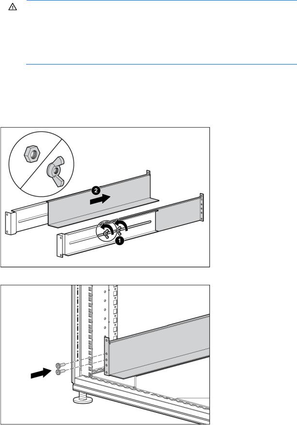
Mounting hardware for squareand round-holed racks is included in the UPS kit. To install the mounting rails:
1.Loosen the wing nuts or hex nuts, and then extend the brackets to the appropriate length.
2.Insert screws through the rack into the mounting rail and the front of each mounting bracket.
Installation 15

3.Install cage nuts or clip nuts into the rear of the rack.
4.Insert screws through the mounting rail into the cage nuts or clip nuts.
Installation 16

5.Tighten the wing nuts or hex nuts.
6.Install the rear stabilization bracket using wing nuts. Wait until the unit is installed and the brackets are adjusted before tightening the nuts.
Installing the UPS in a rack
Before installing the unit, review and adhere to all warnings provided in "Precautions (on page 13)."
WARNING: A risk of personal injury or damage to the equipment exists. Uneven loading of equipment in the rack might cause the rack to become unstable. Install the heavier components first, and then continue to populate the rack from the bottom to the top.
1.Install the mounting rails.
Installation 17
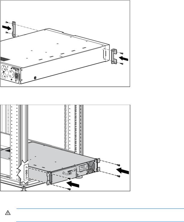
2.Install the mounting ears on the chassis using the screws provided.
3.With one person on each side, lift the chassis to rail level and slide the chassis on the mounting rails.
4.Attach the chassis to the rack using the supplied screws.
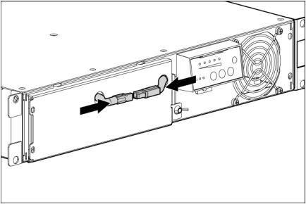
Connecting the battery leads
WARNING: To prevent personal injury from electric shock or damage to the equipment, remove the battery lead labels, and verify that the ERM circuit breakers are in the Off position.
Installation 18
Installation 19
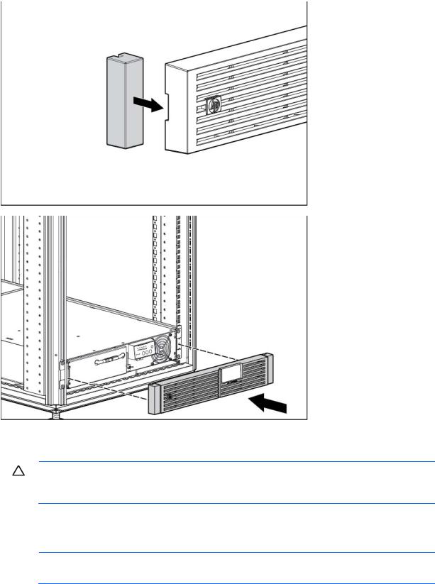
Attaching the UPS front bezel
Connecting the host computer
CAUTION: Only one communications port can be connected to the host computer. Connecting more than one will result in unexpected UPS behavior. If an option card is installed, the serial and USB communications ports are automatically disabled.
Connect the UPS to a host computer using either the USB cable or the DB9 serial cable included with the UPS. Install HP Power Protector on the host computer. See the HP website (http://www.hp.com/go/rackandpower) to download the latest version of HP Power Protector.
NOTE: To install and configure the software, see the software user guide. The software user guide is available for download from the HP website (http://www.hp.com/go/rackandpower).
Installation 20
 651176-002 User Manual")
Connecting the serial communications port
CAUTION: Use only the computer interface cable supplied with the UPS to connect the communications port to the host computer.
IMPORTANT: Power protector software requires the communications port to be appropriately cabled to the host computer.
Connecting the USB communications port
Connecting the REPO port
WARNING: The pins on the REPO port are polarity sensitive. Be sure to verify polarity while connecting the REPO port.
Installation 21

WARNING: To meet the requirements stated in NEC (NFPA 70) Articles 645-10 and 645-11, a UPS installed in a computer equipment room must be connected to a REPO circuit.
IMPORTANT: The remote switch must be in the Off (open) position to enable power to the output receptacles.
NOTE: Wire the connector block using stranded, nonshielded wire (AWG #22 - #18, or equivalent).
Separate wire pairs are attached to a single, normally-open contact in a parallel connection. HP recommends using different colors for the positive and negative wires.
If a connector becomes disconnected and is reconnected with reversed polarity, a REPO is initiated. To avoid REPO port disconnect:
•Minimize wire strain while connecting the REPO port.
Installation 22
•Avoid allowing the wires to hang in the rear of the UPS.
•Use tie wraps and tie wrap blocks to secure the wires tightly to the rack and the rear of the UPS.
For more information about the REPO port, see "REPO port (on page 11)".
For information about verifying the REPO connection, see "Verifying the REPO port connection (on page 44)".
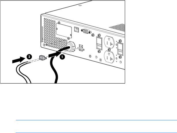
Connecting the ground bonding cable
NOTE: UPS appearance might vary depending on the specific unit installed.
The ground bonding screw is provided as an attachment point for conductors. Use a ground bonding cable if the rack contains any conductors for the purpose of functional grounding or bonding of ungrounded metal parts.
Installation 23
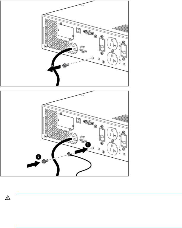
The ground bonding cable is not included.
Connecting the UPS to utility power
WARNING: To prevent injury from electric shock or damage to the equipment:
•Plug the input line cord into a grounded (earthed) electrical outlet that is installed near the equipment and is easily accessible.
•Do not disable the grounding plug on the input line cord. The grounding plug is an important safety feature.
•Do not use extension cords.
Connect the UPS to a grounded utility power outlet. When the UPS is plugged in, it automatically enters Standby mode and begins charging the batteries.
Connecting devices to the UPS
Installation 24
Loading...