


 Loading...
Operating and Service Manual
Agilent 346A/B/C Noise Source
(Including Options
001, 002, and 004)
Serial Numbers
This manual applies directly to instruments with serial numbers prefixed 4124A and below.
Instruments with serial prefixes 4124A and above are supplied with the noise source ENR data preloaded on diskette -
see Chapters 3 & 4.
With changes described in Chapter 2 Manual Changes, this manual also applies to the following prefixes.
Agilent 346B - 2015A and 1935A
Manufacturing Part Number: 00346-90139
July 2001 Supersedes: June 2001
© Copyright 2001 Agilent Technologies

Notice
Information contained in this document is subject to change without notice. Agilent Technologies makes no warranty of any kind with regard to this material, including, but not limited to, the implied warranties of merchantability and fitness for a particular purpose. Agilent Technologies shall not be liable for errors contained herein or for incidental or consequential damages in connection with the furnishings, performance, or use of this material. No part of this document may be photocopied, reproduced, or translated to another language without the prior written consent of Agilent Technologies.
Certification
Agilent Technologies certifies that this product met its published specifications at the time of shipment from the factory. Agilent Technologies further certifies that its calibration measurements are traceable to the United States National Institute of Standards and Technology and/or The United Kingdom National Physics Laboratories, to the extent allowed by the Institution’s calibration facility, and to the calibration facilities of other International Standards Organization members.
Warranty
This Agilent Technologies instrument product is warranted against defects in material and workmanship for a period of one year from date of shipment. During the warranty period, Agilent Technologies will at its option, either repair or replace products which prove to be defective. For warranty service or repair, this product must be returned to a service facility designated by Agilent Technologies. Buyer shall prepay shipping charges to Agilent Technologies and Agilent Technologies shall pay shipping charges, duties, and taxes for products returned to Aglent
ii

Technologies from another country. Agilent Technologies warrants that its software and firmware designated by Agilent Technologies for use with an instrument will execute its programming instructions when properly installed on that instrument. Agilent Technologies does not warrant that the operation of the instrument, or firmware will be uninterrupted or error free.
Limitation of Warranty
The foregoing warranty shall not apply to defects resulting from improper or inadequate maintenance by Buyer, Buyer-supplied software or interfacing, unauthorized modification or misuse, operation outside of the environmental specifications for the product, or improper site preparation or maintenance. NO OTHER WARRANTY IS EXPRESSED OR IMPLIED. AGILENT TECHNOLOGIES SPECIFICALLY DISCLAIMS THE IMPLIED WARRANTIES OF MERCHANTABILITY AND FITNESS FOR A PARTICULAR PURPOSE.
Exclusive Remedies
THE REMEDIES PROVIDED HEREIN ARE BUYER’S SOLE AND EXCLUSIVE REMEDIES. AGILENT TECHNOLOGIES SHALL NOT BE LIABLE FOR ANY DIRECT, INDIRECT, SPECIAL, INCIDENTAL, OR CONSEQUENTIAL DAMAGES, WHETHER BASED ON CONTRACT, TORT, OR ANY OTHER LEGAL THEORY.
Safety Notices
This guide uses warnings and cautions to denote hazards.
iii

WARNING
CAUTION
A warning calls attention to a procedure, practice or the like, which, if not correctly performed or adhered to, could result in injury or the loss of life. Do not proceed beyond a warning until the indicated conditions are fully understood and met.
A caution calls attention to a procedure, practice or the like, which, if not correctly performed or adhered to, could result in damage or the destruction of part or all of the equipment. Do not proceed beyond a caution until the indicated conditions are fully understood and met.
iv

v

Table of Contents |
|
|
Page |
1. General Information |
|
Introduction . . . . . . . . . . . . . . . . . . . . . . . . . . . . . . . . . . . . . . . . . . . . . . . . . . . . . . . . . |
. . 2 |
Specifications . . . . . . . . . . . . . . . . . . . . . . . . . . . . . . . . . . . . . . . . . . . . . . . . . . . . . . |
. . 2 |
Instruments Covered in This Manual . . . . . . . . . . . . . . . . . . . . . . . . . . . . . . . . . . . . |
. . 9 |
Description . . . . . . . . . . . . . . . . . . . . . . . . . . . . . . . . . . . . . . . . . . . . . . . . . . . . . . . . . . |
. 10 |
Model Characteristics of Individual Noise Sources . . . . . . . . . . . . . . . . . . . . . . . . . |
11 |
Warranty. . . . . . . . . . . . . . . . . . . . . . . . . . . . . . . . . . . . . . . . . . . . . . . . . . . . . . . . . . . |
12 |
Equipment Available But Not Supplied . . . . . . . . . . . . . . . . . . . . . . . . . . . . . . . . . . |
12 |
Options . . . . . . . . . . . . . . . . . . . . . . . . . . . . . . . . . . . . . . . . . . . . . . . . . . . . . . . . . . . . |
12 |
Installation. . . . . . . . . . . . . . . . . . . . . . . . . . . . . . . . . . . . . . . . . . . . . . . . . . . . . . . . . . . |
13 |
Handling Precautions . . . . . . . . . . . . . . . . . . . . . . . . . . . . . . . . . . . . . . . . . . . . . . . . |
13 |
Initial Inspection . . . . . . . . . . . . . . . . . . . . . . . . . . . . . . . . . . . . . . . . . . . . . . . . . . . . |
13 |
Original Packaging. . . . . . . . . . . . . . . . . . . . . . . . . . . . . . . . . . . . . . . . . . . . . . . . . . . |
14 |
Mating Connectors . . . . . . . . . . . . . . . . . . . . . . . . . . . . . . . . . . . . . . . . . . . . . . . . . . . |
14 |
Storage and Shipping Environment . . . . . . . . . . . . . . . . . . . . . . . . . . . . . . . . . . . . . |
14 |
Operation . . . . . . . . . . . . . . . . . . . . . . . . . . . . . . . . . . . . . . . . . . . . . . . . . . . . . . . . . . . . |
15 |
Operating Environment. . . . . . . . . . . . . . . . . . . . . . . . . . . . . . . . . . . . . . . . . . . . . . . |
16 |
Recommended Test Equipment . . . . . . . . . . . . . . . . . . . . . . . . . . . . . . . . . . . . . . . . . |
16 |
Operator’s Check . . . . . . . . . . . . . . . . . . . . . . . . . . . . . . . . . . . . . . . . . . . . . . . . . . . . |
17 |
Operator’s Maintenance. . . . . . . . . . . . . . . . . . . . . . . . . . . . . . . . . . . . . . . . . . . . . . . |
22 |
Performance Tests . . . . . . . . . . . . . . . . . . . . . . . . . . . . . . . . . . . . . . . . . . . . . . . . . . . . . |
24 |
Adjustments . . . . . . . . . . . . . . . . . . . . . . . . . . . . . . . . . . . . . . . . . . . . . . . . . . . . . . . . . |
25 |
Replaceable Parts . . . . . . . . . . . . . . . . . . . . . . . . . . . . . . . . . . . . . . . . . . . . . . . . . . . . . |
26 |
Replaceable Parts List . . . . . . . . . . . . . . . . . . . . . . . . . . . . . . . . . . . . . . . . . . . . . . . . |
27 |
Service . . . . . . . . . . . . . . . . . . . . . . . . . . . . . . . . . . . . . . . . . . . . . . . . . . . . . . . . . . . . . . |
29 |
Principles of Operation . . . . . . . . . . . . . . . . . . . . . . . . . . . . . . . . . . . . . . . . . . . . . . . |
29 |
Troubleshooting . . . . . . . . . . . . . . . . . . . . . . . . . . . . . . . . . . . . . . . . . . . . . . . . . . . . . |
29 |
Repair . . . . . . . . . . . . . . . . . . . . . . . . . . . . . . . . . . . . . . . . . . . . . . . . . . . . . . . . . . . . . |
30 |
Returning a Noise Source for Calibration. . . . . . . . . . . . . . . . . . . . . . . . . . . . . . . . . |
30 |
2. Manual Changes
Manual Changes . . . . . . . . . . . . . . . . . . . . . . . . . . . . . . . . . . . . . . . . . . . . . . . . . . . . . . 34
Change A. . . . . . . . . . . . . . . . . . . . . . . . . . . . . . . . . . . . . . . . . . . . . . . . . . . . . . . . . . . 34
3. Using the ENR Data Diskette
vii

Introduction . . . . . . . . . . . . . . . . . . . . . . . . . . . . . . . . . . . . . . . . . . . . . . . . . . . . . . . . . . 36 Loading the ENR Data from Diskette. . . . . . . . . . . . . . . . . . . . . . . . . . . . . . . . . . . . . . 37
Saving the ENR Data to the Noise Figure Analyzer’s Internal Memory . . . . . . . . . . 40 Copying the ENR Data to the Noise Figure Analyzer’s Internal Memory . . . . . . . . . 41
4. ENR File Format |
|
Format Details . . . . . . . . . . . . . . . . . . . . . . . . . . . . . . . . . . . . . . . . . . . . . . . . . . . . . . . . |
44 |
Comment Records . . . . . . . . . . . . . . . . . . . . . . . . . . . . . . . . . . . . . . . . . . . . . . . . . . . . |
44 |
Header Fields . . . . . . . . . . . . . . . . . . . . . . . . . . . . . . . . . . . . . . . . . . . . . . . . . . . . . . . |
44 |
ENR Data. . . . . . . . . . . . . . . . . . . . . . . . . . . . . . . . . . . . . . . . . . . . . . . . . . . . . . . . . . . |
46 |
Examples. . . . . . . . . . . . . . . . . . . . . . . . . . . . . . . . . . . . . . . . . . . . . . . . . . . . . . . . . . . . . |
49 |
A. Caring for Connectors |
|
Introduction . . . . . . . . . . . . . . . . . . . . . . . . . . . . . . . . . . . . . . . . . . . . . . . . . . . . . . . . . . |
52 |
Connector Part Numbers . . . . . . . . . . . . . . . . . . . . . . . . . . . . . . . . . . . . . . . . . . . . . . |
52 |
Handling and Storage . . . . . . . . . . . . . . . . . . . . . . . . . . . . . . . . . . . . . . . . . . . . . . . . . |
52 |
Visual Inspection . . . . . . . . . . . . . . . . . . . . . . . . . . . . . . . . . . . . . . . . . . . . . . . . . . . . . . |
53 |
Obvious Defects and Damage . . . . . . . . . . . . . . . . . . . . . . . . . . . . . . . . . . . . . . . . . . . |
53 |
Mating Plane Surfaces . . . . . . . . . . . . . . . . . . . . . . . . . . . . . . . . . . . . . . . . . . . . . . . . |
53 |
Precision 7 mm Connectors. . . . . . . . . . . . . . . . . . . . . . . . . . . . . . . . . . . . . . . . . . . . . |
54 |
Sexed Connectors . . . . . . . . . . . . . . . . . . . . . . . . . . . . . . . . . . . . . . . . . . . . . . . . . . . . |
55 |
Cleaning . . . . . . . . . . . . . . . . . . . . . . . . . . . . . . . . . . . . . . . . . . . . . . . . . . . . . . . . . . . . . |
57 |
Compressed Air . . . . . . . . . . . . . . . . . . . . . . . . . . . . . . . . . . . . . . . . . . . . . . . . . . . . . . |
57 |
Cleaning Alcohol . . . . . . . . . . . . . . . . . . . . . . . . . . . . . . . . . . . . . . . . . . . . . . . . . . . . . |
57 |
Precision 7 mm Connectors. . . . . . . . . . . . . . . . . . . . . . . . . . . . . . . . . . . . . . . . . . . . . |
58 |
Cleaning Interior Surfaces . . . . . . . . . . . . . . . . . . . . . . . . . . . . . . . . . . . . . . . . . . . . . |
59 |
Drying Connectors. . . . . . . . . . . . . . . . . . . . . . . . . . . . . . . . . . . . . . . . . . . . . . . . . . . . |
60 |
Mechanical Inspection: Connector Gages . . . . . . . . . . . . . . . . . . . . . . . . . . . . . . . . . . . |
61 |
Mechanical Specifications . . . . . . . . . . . . . . . . . . . . . . . . . . . . . . . . . . . . . . . . . . . . . . . |
62 |
Precision 7mm Connectors . . . . . . . . . . . . . . . . . . . . . . . . . . . . . . . . . . . . . . . . . . . . . |
62 |
Sexed Connectors . . . . . . . . . . . . . . . . . . . . . . . . . . . . . . . . . . . . . . . . . . . . . . . . . . . . |
63 |
50 Ohm Type-N Connectors . . . . . . . . . . . . . . . . . . . . . . . . . . . . . . . . . . . . . . . . . . . . |
63 |
75 Ohm Type-N Connectors . . . . . . . . . . . . . . . . . . . . . . . . . . . . . . . . . . . . . . . . . . . . |
64 |
Using Connector Gages . . . . . . . . . . . . . . . . . . . . . . . . . . . . . . . . . . . . . . . . . . . . . . . . . |
65 |
Inspecting and Cleaning the Gage . . . . . . . . . . . . . . . . . . . . . . . . . . . . . . . . . . . . . . . |
65 |
Zeroing the Gage . . . . . . . . . . . . . . . . . . . . . . . . . . . . . . . . . . . . . . . . . . . . . . . . . . . . . |
65 |
Making Connections. . . . . . . . . . . . . . . . . . . . . . . . . . . . . . . . . . . . . . . . . . . . . . . . . . . . |
68 |
Align Connectors Carefully. . . . . . . . . . . . . . . . . . . . . . . . . . . . . . . . . . . . . . . . . . . . . |
68 |
To Make a Preliminary Connection . . . . . . . . . . . . . . . . . . . . . . . . . . . . . . . . . . . . . . |
69 |
Final Connection Using a Torque Wrench . . . . . . . . . . . . . . . . . . . . . . . . . . . . . . . . . |
70 |
Disconnection. . . . . . . . . . . . . . . . . . . . . . . . . . . . . . . . . . . . . . . . . . . . . . . . . . . . . . . . |
71 |
Adapters . . . . . . . . . . . . . . . . . . . . . . . . . . . . . . . . . . . . . . . . . . . . . . . . . . . . . . . . . . . . . |
73 |
Principles of Microwave Connector Care . . . . . . . . . . . . . . . . . . . . . . . . . . . . . . . . . . . |
75 |
viii

1 |
General Information |
1

NOTE
General Information
Introduction
Introduction
This manual contains operating and service information for the Agilent Technologies model 346A, 346B, and 346C Noise Sources.
Included in the manual is information necessary to operate the noise sources.
Specifications
The “Specifications - Table 1-1” on page 3, page 4, and page 5 are performance standards or limits against which the noise source may be tested. These specifications for the noise source when used with a Noise Figure Analyzer are ONLY valid if the analyzer has been allowed to meet its specified warm up time of 60 minutes.
ENR expanded uncertainty analysis and supplemental characteristics are not specifications but are typical characteristics included as additional information for the user.
Specifications are valid at ambient temperature 23 ±1 oCelsius only.
2 |
Chapter 1 |

|
|
|
General Information |
|
|
|
|
Introduction |
|
|
Specifications - Table 1-1 |
|
|
|
Frequency Range |
|
|
|
|
|
|
|
|
|
|
346A/B |
|
10 MHz — 18 GHz |
|
|
|
|
|
|
|
346C |
|
10 MHz — 26.5 GHz |
|
|
|
|
|
|
Operating |
|
|
|
|
Temperature |
|
|
|
|
|
0 oC to 55 oC |
|
|
|
Excess Noise |
|
|
|
|
Ratio (ENR) |
|
|
|
|
Range1 |
|
|
|
|
|
|
|
||
|
346A |
4.5 - 6.5 dB |
||
|
|
|
||
|
346B |
1416 dB |
||
|
|
|
||
|
346C |
12 - 17 dB |
||
|
|
|
|
|
1.ENR values are given at cardinal frequency points over the frequency range of each noise source. Calibrated values at cardinal frequencies printed on each noise source label and on a separate report supplied with each Agilent 346 Noise Source. Specifications are valid at calibration temperature only.
Chapter 1 |
3 |
General Information
Introduction
Specifications - Table 1-1 Continued
Maximum
Standing Wave
Ratio (SWR) and
Reflection
Coefficient (r) for
Source ON/OFF
States
Instrument model |
Frequency Range |
Maximum |
Reflection |
|
|
(GHz) |
Standing Wave |
Coefficient |
|
|
|
|
Ratio (SWR) |
(Rho) (r) |
|
|
|
|
|
346A/B1 |
0.01 |
- 0.03 |
<1.3:1 |
0.13 |
|
0.03 |
- 5.0 |
<1.15:1 |
0.07 |
|
|
|
|
|
|
5.0 - 18.0 |
<1.25:1 |
0.11 |
|
|
|
|
|
|
346C |
0.01-18.0 |
<1.25:1 |
0.11 |
|
|
|
|
|
|
|
18.0 |
- 26.5 |
<1.35:1 |
0.15 |
|
|
|
|
|
1.Maximum change in complex reflection coefficient between source ON and source OFF at all frequencies for 346A only: 0.01.
4 |
Chapter 1 |

General Information
Introduction
Specifications - Table 1-1 Continued
Impedance
50 ohm nominal
Maximum reverse power
1 Watt
Power required
28 ±1 V
346A/B |
60 mA peak, 30 mA average for source ON |
|
|
346C |
45 mA |
|
|
Connectors1
346 |
Output |
APC-3.5 (male) standard1 |
|
|
|
346 |
Input |
Bias: BNC (f) |
|
|
|
1.Also mates with female SMA connectors. See option information for other connector styles.
Dimensions
140 x 21 x 31mm (5.5 x 0.8 x 1.2 in)
Net Weight
0.1kg (3.5 oz.)
1.For correct connector usage, refer Table A-2 for the torque settings.
Chapter 1 |
5 |
General Information
Introduction
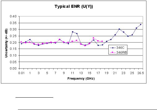
Excess Noise Ratio Expanded Uncertainty (U(Y)) - Table 1-2
ENR values are given at cardinal frequency points over the frequency range of each noise source. These ENR values are printed on the noise source label and on a separate printed report supplied with the 346 Noise Source. Included in the printed report is the measurement uncertainty for each cardinal frequency point.
A significant proportion of the expanded uncertainty (U(Y)) is based on the uncertainties provided by the United States National Institute of Standards and Technology (NIST) and/or The United Kingdom National Physics Laboratories (NPL). Agilent therefore reserve the right to change the overall expanded uncertainties based on changes in uncertainty values within the National Standards Institutes.
Uncertainties are valid at ambient temperature 23°C ±1°C (296K) only.
A typical characteristic plot of ENR (U(Y)) versus each cardinal frequency point is shown in Figure 1-1. the uncertainties given are typical - refer to the printed calibration report for the actual uncertainties for your noise source.
Figure 1-1 |
Characteristic1ENR Plot versus Cardinal Frequency Points |
1. Characteristic values are met or bettered by 90% of instruments with 90% confidence.
6 |
Chapter 1 |

General Information
Introduction
Excess Noise Ratio Expanded Uncertainty (U(Y)) - Table 1-2
Continued
Characteristic
ENR (U(Y))
Specification
Instrument model |
Frequency |
ENR Uncertainty (±dB)1 |
|
|
(GHz) |
|
|
|
|
|
|
346A |
0.01- 1.5 |
0.21 |
|
|
|
|
|
|
1.5 |
- 3.0 |
0.20 |
|
|
|
|
|
3.0 |
- 7.0 |
0.20 |
|
|
|
|
|
7.0 |
- 18.0 |
0.23 |
|
|
|
|
346B |
0.01- 1.5 |
0.20 |
|
|
|
|
|
|
1.5 |
- 3.0 |
0.19 |
|
|
|
|
|
3.0 |
- 7.0 |
0.20 |
|
|
|
|
|
7.0 |
- 18.0 |
0.23 |
|
|
|
|
346C |
0.01- 1.5 |
0.22 |
|
|
|
|
|
|
1.5 |
- 3.0 |
0.19 |
|
|
|
|
|
3.0 |
- 7.0 |
0.20 |
|
|
|
|
|
7.0 |
- 18.0 |
0.28 |
|
|
|
|
|
18.0 - 26.5 |
0.34 |
|
|
|
|
|
1.Characteristic values are met or bettered by 90% of instruments with 90% confidence.
Chapter 1 |
7 |

General Information
Introduction
Supplemental Characteristics - Table 1-3
Supplemental
Characteristics
ENR variation with |
<0.01 dB/°C for 30 MHz to 26.5 GHz |
temperature: |
|
|
|
ENR variation with |
Internal current regulator for <0.02 dB variation |
voltage: |
for 28 ±1 V |
|
|
Switching speed: |
|
For repetitive operation (in previous state for less than 5 seconds):
Turn-on: < 20 μs
Turn-off: <80 μs
For single-shot operation (in previous state more than 5 seconds):
Turn-on: < 3 ms
Turn-off: <80 μs
8 |
Chapter 1 |

NOTE
General Information
Instruments Covered in This Manual
Instruments Covered in This Manual
The noise sources covered by this manual have a two-part serial number. The first four digits and letter constitute the serial number prefix. The last five digits form a sequential suffix that is unique to each noise source. The prefix is the same for all noise sources of a particular configuration. It will change when a design modification occurs. The contents of this manual apply directly to those instruments having the same serial number prefixes listed under SERIAL NUMBERS on the title page.
A noise source manufactured after the printing of this manual may have a serial number prefix which is not listed on the title page. This unlisted serial number prefix indicates the noise source is different than those documented in this manual. If manual changes are needed, the manual for this newer noise source is accompanied by a Manual Changes supplement. The supplement contains "change information" that explains how to adapt this manual to the newer noise source.
In addition to change information, the supplement may contain information for correcting errors in the manual. The supplement is identified with the manual print date and part number, both of which appear on the manual title page.
For information concerning a serial number prefix that is not listed on the title page in the Manual Change supplement, contact your nearest Agilent Technologies office.
Agilent/Hewlett-Packard 346 Noise Sources which were manufactured before the printing of this manual will have a serial number prefix lower than the one listed on the title page. Manual changes for these older models are found in Chapter 2 “Manual Changes”.
Agilent Technologies are migrating their existing product serial numbers to a new format. All new products use this new format. The format is the first two letters signify the country of manufacture, for example, US representing the USA, the next four numbers,the serial number prefix, and the last five numbers form a sequential suffix that is unique to each product. For example, US123456789, where 1234 is the prefix and 56789 is the suffix. The two letters MY represent Malaysia.
Chapter 1 |
9 |
General Information
Description
Description
The noise source produces noise output (power-on) when +28 V is applied. When it is off, there is residual noise due to thermal agitation in the noise source (power-off). These two noise levels are used to measure the gain and added noise of the device under test, and consequently, its noise figure.
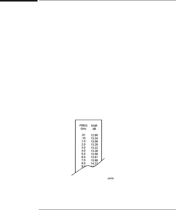
The Excess Noise Ratio (ENR) for each noise source has been measured at major frequencies and recorded on a label attached to the noise source (see Figure 1-2). ENR references power-on to the noise power that exists at 290 Kelvin (17 °C ). In addition, a separate calibration sheet showing the complex reflection coefficient in both the on and off states is included with each instrument.
All three models are provided with a BNC female connector for power input. The output connector is a male APC-3.5 on the standard noise sources. Type-N and APC-7 connectors are available as options for the Agilent 346A and 346B Noise Sources. In addition to these general characteristics, certain characteristics apply to the specific models. These characteristics are listed in Table 1-4.
Figure 1-2 |
A Partial View of Typical Calibration Label |
10 |
Chapter 1 |

|
|
|
General Information |
|
|
|
Description |
Table 1-4 |
Model Characteristics of Individual Noise Sources |
||
Agilent 346A |
|
Agilent 346B |
Agilent 346C |
|
|
|
|
Reflection coefficient differential |
Reflection coefficient |
Reflection coefficient |
|
between on and off states is specified |
differential between on and off |
differential between on and off |
|
to be no greater than 0.01. |
states is not specified, but is |
states is not specified, but is |
|
|
|
less than 0.1 typically. |
less than 0.1 typically. |
|
|
|
|
Specified output noise spectrum |
Specified output noise |
Specified output noise |
|
from 10 MHz to 18 GHz. |
spectrum from 10 MHz to |
spectrum from 10 MHz to |
|
|
|
18 GHz. |
26.5 GHz. |
|
|
|
|
Nominal ENR is 6 dB over the |
Nominal ENR is 15 dB over the |
Nominal ENR is 15 dB over the |
|
specified frequency range. |
specified frequency range. |
specified frequency range. |
|
|
|
|
|
Not directly usable for |
Suitable for Agilent/HP 8970A |
Suitable for Agilent/HP 8970A |
|
Agilent/HP 8970A IF attenuator |
IF attenuator calibration |
IF attenuator calibration |
|
calibration (Special Function |
(Special Function 33). |
(Special Function 33). |
|
33). 10 dB of gain is required. |
|
|
|
|
|
|
|
Not directly usable for |
Suitable for Agilent/HP 8970B |
Suitable for Agilent/HP 8970B |
|
Agilent/HP 8970B IF attenuator |
IF attenuator calibration. |
IF attenuator calibration. |
|
calibration. Refer to |
|
Refer to "Calibration, IF |
Refer to "Calibration, IF |
"Calibration, IF Attenuators" in |
Attenuators" in the Agilent/HP |
Attenuators" in the Agilent/HP |
|
the Agilent/HP 8970B Operating |
8970B Operating Manual. |
8970B Operating Manual. |
|
Manual. |
|
|
|
|
|
|
|
Chapter 1 |
11 |
General Information
Description
Warranty
The noise sources are warranted and certified as indicated in this manual. Connector damage resulting from improper use is not covered under warranty.
|
Equipment Available But Not Supplied |
|
The following equipment is available from Agilent Technologies for use |
|
with the noise sources: |
|
• 8710-1766: 3/4" Torque Wrench (APC-7) |
|
• 5060-0344: 9/16" Torque Wrench (APC-3.5) |
|
|
NOTE |
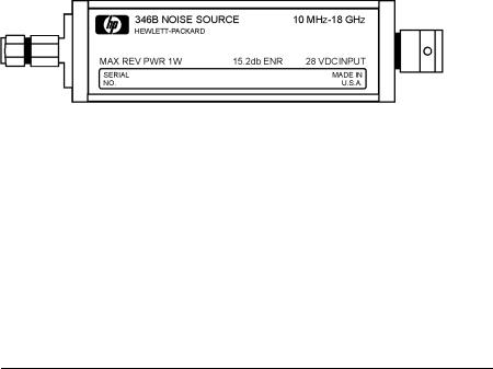
Agilent/HP Model 346B Noise Sources with serial prefixes of 2037A and |
|
below, have an APC-3.5 connector of a different configuration (See Figure |
|
1-3). The 9/16" torque wrench will not fit these older models. |
|
|
Figure 1-3 |
Agilent/HP Noise source with Older APC-3.5 Connector |
Options
The Agilent 346A and 346B Noise Sources are available with the following output connector options:
•Option 001, Type-N (male)
•Option 002, APC-7
•Option 004, Type-N (female)
Since the APC-7 and Type-N connectors do not operate up to 26.5 GHz, no output connector options are available for the Agilent 346C.
12 |
Chapter 1 |

CAUTION
CAUTION
General Information
Installation
Installation
Handling Precautions
Do not disassemble the noise source. The diode module is static sensitive and can be damaged or the calibration can be altered.
Do not drop the noise source. Dropping can damage the unit or alter the calibration.
Proper connector care is essential. See Operator’s Maintenance in the Operation section of this manual for more information.
Initial Inspection
Inspect the shipping container for damage. Inspect the noise source for mechanical damage incurred in transit. If the shipping container or cushioning material is damaged, it should be kept until the contents of the shipment have been checked for completeness and the noise source has been mechanically and electrically checked. If the contents are incomplete, if there is mechanical damage or a defect, or if the noise source does not work electrically, notify the nearest Agilent Technologies office. If the shipping container is damaged, or the cushioning material shows signs of unusual stress, notify the carrier as well as the Agilent Technologies office. Keep the shipping materials for the carrier’s inspection.
Chapter 1 |
13 |
General Information
Installation
Original Packaging
Container and materials identical to those used in factory packaging are available through Agilent Technologies offices. If the noise source is being returned to Agilent Technologies for servicing, attach a tag indicating the name and address of the company, the technical contact person, phone number and extension, the model number, serial number, type of service being requested, and failure symptoms if applicable. Mark the shipping container FRAGILE. In any correspondence, refer to the noise sources by model number and serial number.
Mating Connectors
The noise sources can be mated with other instrumentation having the connectors listed in Table 1-5.
Table 1-5 |
Connectors That Can Be Mated With the Noise Sources |
||
|
Configuration |
Mating Connector |
|
|
|
|
|
|
Input: all units |
BNC male1 |
|
|
Output: standard |
APC-3.5 female |
|
|
|
SMA female |
|
|
|
|
|
|
Opt.001 |
Type-N female |
1 |
|
|
|
|
|
|
|
|
|
Opt.002 |
APC-7 |
|
|
|
|
|
|
Opt.004 |
Type-N male1 |
|
|
|
|
|
|
1Must comply with U.S. Military Standard MII,C-39012 |
||
Storage and Shipping Environment
The noise sources should be stored in a clean, dry environment. The following environmental limitations apply to both storage and shipment:
•Temperature: -55 °C to +75 °C
•Humidity: <95% relative
•Altitude: <15300 meters (50000 feet)
14 |
Chapter 1 |
CAUTION
NOTE
Figure 1-4
General Information
Operation
Operation
This section refers to operation with noise figure meters. For more detailed operating instructions, refer to the operating manual for the noise figure meter used.
Use a dc blocking capacitor to protect the noise source from damage when connected to any system where a dc voltage is present on the output center conductor.
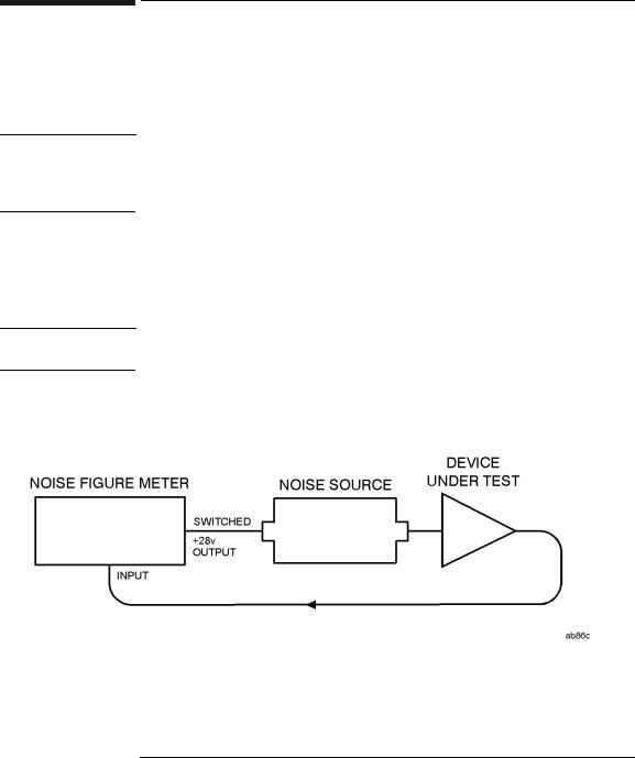
Noise figure measurements of devices (such as amplifiers, mixers, transistors, and receivers) can be made using the noise source with a noise figure meter. Figure 1-4 depicts a simple test setup for a noise figure measurement.
The noise figure meter must have a +28 ±1 V switched supply.
Typical Noise Figure Measurement Test Setup
Chapter 1 |
15 |

General Information
Operation
Operating Environment
The operating environment of the noise sources should be within the following limitations:
•Temperature: 0 °C to +55 °C
•Humidity: <95% relative
•Altitude: <4600 metres (15 000 feet)
Recommended Test Equipment
Table 1-6 is a list of equipment that can be used to perform an operational verification check.
Table 1-6 |
Recommended Test Equipment For Operator’s Checks |
|||
Check |
|
Instrument |
Critical Specification |
Recommended Model |
No. |
|
|
|
|
|
|
|
|
|
1 |
|
Power Meter and Power |
Minimum Sensitivity: 0.1 nW |
Agilent/HP E4418A |
|
|
Sensor |
Frequency Range: 10 MHz to |
with |
|
|
|
||
|
|
|
18 GHz |
Agilent/HP 8481D, or |
|
|
|
|
|
|
|
|
|
E4412A, or E9300A |
|
|
|
|
|
|
|
Power Supply |
Voltage: 28.0 ±1.0 V |
Agilent/HP 6028A |
|
|
|
Current: 100 mA |
|
|
|
|
|
|
2 |
|
Noise Figure Meter |
Voltage Output: 28.0 ±1.0 V |
Agilent/HP 8970B |
|
|
|
Input Noise Figure:<7.4 FdB |
or |
|
|
|
at 100 MHz |
Agilent N8972/3/4/5A |
|
|
|
|
|
|
|
|
|
|
16 |
Chapter 1 |
General Information
Operation
Operator’s Check
The operator’s checks in this section should be performed if failure of the noise source is suspected. The checks can be used only to verify that the noise sources are producing a broadband noise spectrum. They cannot be used to check the units against specifications. Only one of the checks is necessary to verify operation. Table 1-6 shows the recommended test equipment used for each check.
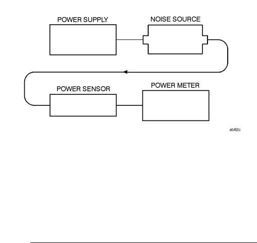
Operator’s Check with Power Meter (Check 1)
Step 1. Connect the equipment as shown in Figure 1-5.
Figure 1-5 |
Operator’s Check Test Setup 1 |
Step 2. Turn the power supply OFF. Zero the power meter.
Step 3. Turn the power supply ON (+28 V). Measure the power output with the noise source on.
Step 4. Verify that the result of the measurement is within the following limits and hence the noise source is operating correctly:
•Agilent 346A Power output = -66 ±4 dBm.
•Agilent 346B Power output = -56 ±4 dBm.
•Agilent 346C Power output = -56 ±4 dBm.
Chapter 1 |
17 |
General Information
Operation
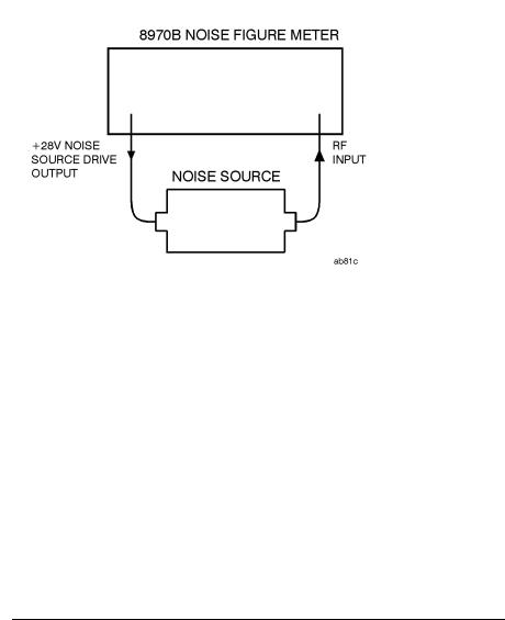
Operator’s Check with Agilent/HP 8970B Noise Figure Meter (Check 2a)
Step 1. Remove any cables from the noise figure meter input. Press PRESET. After 5 seconds, verify the noise figure display shows --FdB and the left display shows 30 MHz.
Step 2. Connect the equipment as shown in Figure 1-6.
Figure 1-6 |
Operator’s Check Test Setup 2a |
Step 3. Enter a tuned frequency of 100 MHz. (See "Fixed Frequency Tuning" in the Agilent/HP 8970B Operating Manual).
Step 4. Enter special function 5.3 to enable the instrument for spot ENR entry. (See "Special Functions" in the Agilent/HP 8970B Operating Manual).
Step 5. Enter the ENR at 100 MHz from the noise source calibration label. (See "Spot ENR, Thot, and TCold, in the Agilent/HP 8970B Operating Manual).
Step 6. Confirm that the noise source is operating correctly.
The noise figure measurement of the noise figure meter will appear in the noise figure display. If the result of the measurement is less than 7.4 FdB, the noise source is operating.
Step 7. Press PRESET to return the instrument to preset conditions.
18 |
Chapter 1 |
Loading...