


TM 11-6625-2495-14&P
TECHNICAL MANUAL
OPERATOR’S, ORGANIZATIONAL, DIRECT SUPPORT, AND GENERAL SUPPORT MAINTENANCE MANUAL (INCLUDING REPAIR PARTS AND SPECIAL TOOLS LISTS)
FOR
GENERATOR, SIGNAL SG-747/U (HEWLETT-PACKARD 3300A)
(NSN 6625-00-118-6736)
HEADQUARTERS, DEPARTMENT OF THE ARMY
4 AUGUST 1980
5 |
1 |
2 |
3 |
4 |
5 |
SAFETY STEPS TO FOLLOW IF SOMEONE IS THE VICTIM OF ELECTRICAL SHOCK
DO NOT TRY TO PULL OR GRAB THE INDIVIDUAL
IF POSSIBLE, TURN OFF THE ELECTRICAL POWER
IF YOU CANNOT TURN OFF THE ELECTRICAL POWER, PULL, PUSH, OR LIFT THE PERSON TO SAFETY USING A DRY WOODEN POLE OR A DRY ROPE OR SOME OTHER INSULATING MATERIAL
SEND FOR HELP AS SOON AS POSSIBLE
AFTER THE INJURED PERSON IS FREE OF CONTACT WITH THE SOURCE OF ELECTRICAL SHOCK, MOVE THE PERSON A SHORT DISTANCE AWAY AND IMMEDIATELY START ARTIFICIAL RESUSCITATION
TM 11-6625-2495-14&P
WARNING
Adequate ventilation should be provided while using TRICHLOROTRIFLUOROETHANE. Prolonged breathing of vapor should be avoided. The solvent should not be used near heat or open flame; the products of decomposition are toxic and irritating. Since TRICHLOROTRIFLUOROETHANE dissolves natural oils, prolonged contact with skin should be avoided. When necessary, use gloves which the solvent cannot penetrate. If the solvent is taken internally, consult a physician immediately.
WARNING
When the output ground is floated above Power Line Ground, all BNC connectors will be at the offset voltage.
a/(b blank)

TM 11-6625-2495-14&P
This manual contains copyrighted material which is reproduced by permission of the HEWLETT-PACKARD Company.
TECHNICAL MANUAL |
HEADQUARTERS |
|
DEPARTMENT OF THE ARMY |
No. 11-6625-2495-14&P |
WASHINGTON, DC, 4 August 1980 |
|
OPERATOR’S, ORGANIZATIONAL, DIRECT SUPPORT, |
|
AND GENERAL SUPPORT MAINTENANCE MANUAL, |
|
(INCLUDING REPAIR PARTS AND SPECIAL TOOLS LISTS) |
|
FOR |
|
GENERATOR, SIGNAL SG-747/U |
|
(HEWLETT-PACKARD 3300A) |
|
(NSN 6625-00-118-6736) |
REPORTING OF ERRORS
You can improve this manual by recommending improvements using DA Form 2028-2 located in the back of the manual. Simply tear out the self-addressed form, fill it out as shown on the sample, fold it where shown, and drop it in the mail.
If there are no blank DA Forms 2028-2 in back of your manual, use the standard DA Form 2028 (Recommended Changes to Publications and Blank Forms) and forward it to the Commander, US Army Communications and Electronics Materiel Readiness Command, ATTN: DRSEL-ME-MQ, Fort Monmouth, NJ 07703.
In either case, a reply will be furnished direct to you.
|
|
TABLE OF CONTENTS |
|
SECTION |
|
|
Page |
0 |
INTRODUCTION............................................................................ |
0-1 |
|
|
0-1. SCOPE................................................................................... |
0-1 |
|
|
0-2. INDEXES OF PUBLICATIONS.............................................. |
0-1 |
|
|
0-3. FORMS AND RECORDS....................................................... |
0-1 |
|
|
0-4. |
REPORTING EQUIPMENT IMPROVEMENT |
|
|
|
RECOMMENDATIONS (EIR) ................................................ |
0-1 |
|
0-5. |
ADMINISTRATIVE STORAGE .............................................. |
0-1 |
|
0-6. |
DESTRUCTION OF ARMY ELECTRONICS MATERIAL ...... |
0-1 |
This manual is an authentication of the manufacturer’s commercial literature which through usage, has been found to cover the data required to operate and maintain this equipment. The manual was not prepared in accordance with military specifications and AR 310-3, the format has not been structured to consider levels of maintenance.
i
|
|
|
|
|
|
TM 11-6625-2495-14&P |
|
|
|
TABLE OF CONTENTS (Continued) |
|
|
|||
Section |
|
|
Page |
Section |
|
|
Page |
I |
GENERAL INFORMATION ........................ |
1-1 |
V |
MAINTENANCE (Cont’d) |
|
||
|
1-1. |
General.......................................... |
1-1 |
|
5-13. |
Maximum Output Level, |
|
|
1-5. |
Electronic Frequency Control ........ |
1-1 |
|
|
Loaded.................................... |
5-1 |
|
1-7. |
Output System............................... |
1-1 |
|
5-16. |
Square Wave Response ............... |
5-2 |
|
1-9. |
Instrument and Manual |
|
|
5-18. |
Sync Output .................................. |
5-2 |
|
|
Identification............................ |
1-1 |
|
5-19. |
Remote Frequency Control |
|
Section |
|
|
Page |
|
|
Check ..................................... |
5-2 |
II |
INSTALLATION.......................................... |
2-1 |
|
5-20. |
Channel B-A Check ...................... |
5-3 |
|
|
2-1. |
Introduction.................................... |
2-1 |
|
5-21. |
Adjustment and Calibration........... |
5-3 |
|
2-3. |
Initial Inspection............................. |
2-1 |
|
5-22. |
Cover Removal ............................. |
5-3 |
|
2-5. |
Power Requirements..................... |
2-1 |
|
5-23. |
Power Supply Adjustments ........... |
5-3 |
|
2-7. |
Grounding Requirements .............. |
2-1 |
|
5-26. |
Power Supply Ripple Check.......... |
5-3 |
|
2-10. |
Installation ..................................... |
2-1 |
|
5-27. |
Power Supply Regulation Check... |
5-3 |
|
2-12. |
Bench Mounting ............................ |
2-1 |
|
5-28. |
Oven Regulation. .......................... |
5-3 |
|
2-14. |
Rack Mounting .............................. |
2-1 |
|
5-29. |
Frequency Symmetry Adjust......... |
5-3 |
|
2-16. |
Repackaging for Shipment ............ |
2-1 |
|
5-32. |
Current Source Adjust................... |
5-5 |
Section |
|
|
Page |
|
5-33. |
Dial Adjustment............................. |
5-5 |
III |
OPERATING INSTRUCTIONS .................. |
3-1 |
|
5-34. |
Dial Calibrate................................. |
5-5 |
|
|
3-1. |
Introduction.................................... |
3-1 |
|
5-38. |
Distortion Adjust............................ |
5-6 |
|
3-3. |
Controls and Indicators ................. |
3-1 |
|
5-39. |
DC Output Level Adjust ................ |
5-6 |
|
3-5. |
Turn On Procedure........................ |
3-1 |
|
5-41. |
Square Wave Adjust ..................... |
5-6 |
|
3-7. |
Operating Instructions ................... |
3-1 |
|
5-43. |
Repair Procedures. ....................... |
5-6 |
Section |
|
|
Page |
|
5-44. |
Servicing Etched Circuit Boards ... |
5-6 |
IV |
THEORY OF OPERATION ........................ |
4-1 |
|
5-46. |
Servicing Rotary Switches ............ |
5-7 |
|
|
4-1. |
Introduction.................................... |
4-1 |
|
5-48. |
Replacement of Factory |
|
|
4-3. |
General Description....................... |
4-1 |
|
|
Selected Components ............ |
5-7 |
|
4-13. |
Schematic Theory ......................... |
4-2 |
|
5-50. |
Troubleshooting Procedure........... |
5-7 |
|
4-14. |
Frequency Control Network........... |
4-2 |
|
5-54. |
Malfunction Isolation Plug ............. |
5-7 |
|
4-17. |
Current Sources ............................ |
4-2 |
|
5-56. |
Precautions ................................... |
5-8 |
|
4-19. |
Triangle Integrator ......................... |
4-2 |
|
5-59. |
Troubleshooting Tree.................... |
5-8 |
|
4-21. |
Voltage Comparator |
|
|
5-62. |
Troubleshooting Tables ................ |
5-10 |
|
|
Multivibrator ............................ |
4-2 |
Section |
|
|
Page |
|
4-23. |
Sine Wave Synthesizer. ................ |
4-2 |
VI |
CIRCUIT DIAGRAMS ................................ |
6-1 |
|
|
4-25. |
Output Amplifiers........................... |
4-2 |
|
6-1. |
Introduction ................................... |
6-1 |
|
4-27. |
Power Supply ................................ |
4-3 |
|
6-3. |
Schematic Diagrams..................... |
6-1 |
|
4-30. |
Oven.............................................. |
4-3 |
|
6-4. |
Component Location Diagrams .... |
6-1 |
Section |
|
|
Page |
|
6-5. |
Plug-In Receptacle........................ |
6-1 |
V |
MAINTENANCE ......................................... |
5-1 |
Section |
|
|
Page |
|
|
5-1. |
Introduction.................................... |
5-1 |
VII |
REPLACEABLE PARTS ............................ |
7-1 |
|
|
5-3. |
Performance Checks..................... |
5-1 |
|
7-1. |
Introduction ................................... |
7-1 |
|
5-5. |
Dial Accuracy................................. |
5-1 |
|
7-4. |
Ordering Information ..................... |
7-1 |
|
5-7. |
Distortion Check ............................ |
5-1 |
|
7-6. |
Non-Listed Parts ........................... |
7-1 |
|
5-8. |
Frequency Response .................... |
5-1 |
Appendix |
|
|
|
|
5-10. |
Maximum Output Level, |
|
A |
References................................................. |
A-1 |
|
|
|
No Load .................................. |
5-1 |
B |
Not Applicable. |
|
|
|
|
|
|
C |
Not Applicable. |
|
|
|
|
|
|
D |
Maintenance Allocation.............................. |
D-1 |
|
|
|
|
LIST OF TABLES |
|
|
|
|
Number |
|
|
Page |
Number |
|
|
Page |
1-1. |
Specifications ............................................. |
1-0 |
5-4. |
Troubleshooting Aid ................................... |
5-8 |
||
5-1. |
Required Test Equipment........................... |
5-0 |
5-5. |
Maintenance Correlation Table.................. |
5-10 |
||
5-2. |
Power Supply Adjustments......................... |
5-3 |
5-6. |
Factory Selected Components................... |
5-11 |
||
5-3. |
Integrator Feedback Capacitance. ............. |
5-7 |
7-1. |
Replaceable Parts...................................... |
7-2 |
||
|
|
|
|
7-2. |
Part No - National Stock |
|
|
|
|
|
|
|
No. Cross Reference Index.................. |
7-9 |
|
ii
|
|
|
|
TM 11-6625-2495-14&P |
|
|
|
LIST OF ILLUSTRATIONS |
|
||
Number |
|
Page |
Number |
|
Page |
1-1. |
Model 3300A Function Generator .............. |
1-0 |
5-7. |
Malfunction Isolating Plug .......................... |
5-8 |
3-1. |
Description of Front and Rear Panel |
|
5-8. |
Troubleshooting Tree................................. |
5-9 |
|
Controls and Connectors....................... |
3-0 |
5-9. |
Normal Oscillator Wave Forms .................. |
5-10 |
4-1. |
Block Diagram ............................................ |
4-1 |
6-1. |
3300A Top and Bottom Views ................... |
6-2 |
5-1. |
600 ohm or 50 ohm Load Output Test |
|
6-2. |
Oscillator Circuit Schematic (A11, A13 |
|
|
Setup ..................................................... |
5-2 |
|
and A14)................................................ |
6-3 |
5-2. |
Remote Frequency Control Test Setup...... |
5-2 |
6-3. |
Range Switch Connections to Plug-In Unit 6-4 |
|
5-3. |
Adjustment Point Location.......................... |
5-4 |
6-4. |
Output Amplifiers Schematic |
|
5-4. |
Voltage Monitoring Points Top and |
|
|
(A15 and A16) .................................... |
6-5/6-6 |
|
Bottom ................................................... |
5-4 |
6-5. |
Power Supply Schematic (A12 and A11) 6-7/6-8 |
|
5-5. |
Symmetry Adjustment ................................ |
5-5 |
6-6. |
J6 Plug-In Receptacle................................ |
6-9 |
5-6. |
DC Output Level Adjust Test Setup ........... |
5-5 |
7-1. |
Modular Cabinet Parts ............................... |
7-0 |
iii
TM 11-6625-2495-14&P
SECTION 0
INTRODUCTION
0-1. SCOPE.
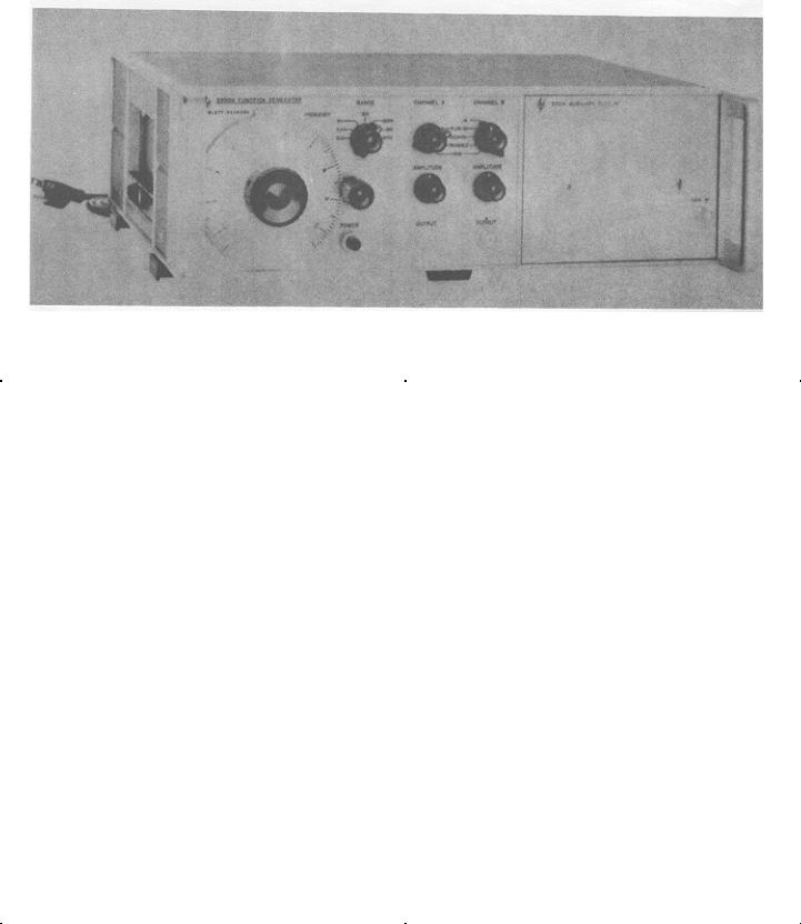
This manual describes Generator, Signal SG-747/U (HP-3300A) (fig. 1-1) and provides maintenance instructions. Throughout this manual, SG-747/U is referred to as the Hewlett-Packard HP-3300A Function Generator.
0-2. INDEXES OF PUBLICATIONS.
a.DA Pam 310-4. Refer to the latest issue of DA Pam 310-4 to determine whether there are new editions, changes, or additional publications pertaining to the equipment.
b.DA Pam 310-7. Refer to DA Pam 310-7 to determine whether there are modification work orders (MWO’s) pertaining to the equipment.
0-3. FORMS AND RECORDS.
a.Reports of Maintenance and Unsatisfactory Equipment. Maintenance forms, records, and reports which are to be used by maintenance personnel at all levels of maintenance are listed in and prescribed by TM 38-750.
b.Report of Packaging and Handling Deficiencies. Fill out and forward DD Form 6 (Packaging Improvement Report) as prescribed in AR 735-11-2/NAVSUPINST 4440,127E/AFR 400-54/MCO 4430.3E and DSAR 4140.55.
c.Discrepancy in Shipment Report (DISREP) (SF 361). Fill out and forward Discrepancy in Shipment Report (DISREP) (SF 361) as prescribed in AR 55-38/NAVSUPINST 4610.33B/AFR 75-18/MCO P4610.19C and DSAR 4500.15.
0-4. REPORTING OF EQUIPMENT IMPROVEMENT RECOMMENDATIONS (EIR).
EIRs will be prepared using DA Form 2407, Maintenance Request. Instructions for preparing EIRs are provided in TM 38-750, The Army Maintenance Management System. EIRs should be mailed directly to Commander, US Army Communications and Electronics Materiel Readiness Command, ATTN: DRSEL-ME-MQ, Fort Monmouth, New Jersey 07703. A reply will be furnished directly to you.
0-5. ADMINISTRATIVE STORAGE.
Administrative storage of equipment issued to and used by Army activities shall be in accordance with TM 740-90-
1.
0-6. DESTRUCTION OF ARMY ELECTRONICS MATERIEL.
Destruction of Army Electronics materiel to prevent enemy use shall be in accordance with TM 750-244-2.
0-1
TM 11-6625-2494-14&P
Figure 1-1. Model 3300A Function Generator
Table 1-1. |
Specifications |
|
AVAILABLE PLUG-IN UNITS: |
|
SINE WAVE DISTORTION: <1%. 0.01 Hz to 10 |
Model 3301A Auxiliary Plug-In. |
|
kHz; <3%, 10 kHz to 100kHz on the X10K range. |
Model 3302A Trigger Plug-In. |
|
|
Model 3304A Sweep/Offset Plug-In. |
|
SQUARE WAVE RESPONSE: <250 nsec rise and |
Model 3305A Sweep Plug-In. |
|
fall time on all ranges; <500 nsec rise and fall |
|
|
time in -A; <1% sag; <5% overshoot at full out- |
OUTPUT WAVEFORMS: Sinusoidal, square, and |
|
put; <1% symmetry error. |
triangle selected by panel switch. (Any two |
|
|
outputs available simultaneously. |
|
TRIANGLE LINEARITY: <1% 0.01 Hz to 10 kHz; |
|
|
<2%, 10 kHz to 100 kHz at full output; < 1% |
FREQUENCY RANGE: 0.01 Hz to 100 kHz in |
|
symmetry error. |
seven decade ranges. |
|
SYNC PULSE OUTPUT: > 10 volts peak-to-peak |
FREQUENCY RESPONSE: ± 1%, 0.01 Hz to 10 |
|
|
|
open circuit, <5 μsec duration. Sync pulse |
|
kHz; ± 3%, 10 kHz to 100 kHz on the X10K |
|
occurs at crest of sine and triangle wave. |
range. |
|
DC STABILITY: Drift: <±0.25%6 of peak-to-peak |
|
|
|
DIAL ACCURACY:. ± 1% of maximum dial setting |
|
amplitude over a period of 24 hours. (After 30 |
(1 minor division) 0. 01 Hz to 10 kHz; ±2% of |
|
minute warmup). |
maximum dial setting (2 minor divisions) 10 |
|
|
kHz to 100 kHz. T. C. 0. 1%/°C. |
|
REMOTE FREQUENCY CONTROL: 0 to -10 volts |
|
|
will linearly change frequency > 1 decade with- |
MAXIMUM OUTPUT PER CHANNEL: > 35 volts |
|
in a single range. Frequency resetability with |
peak-to-peak open circuit; > 15 volts peak-to- |
|
respect to voltage ±1% of maximum frequency |
peak into 600 ohms; > 2 volts peak-to-peak into |
|
on range selected. |
50 ohms. |
|
POWER: 115 or 230 volts ±10%, 48 to 440 Hz. |
|
|
|
OUTPUT ATTENUATORS (both channels): 40 dB |
|
Less than 50 watts. |
range. |
|
DIMENSIONS: (inches and millimeters) 5" high |
|
|
|
OUTPUT IMPEDANCE: 600 ohms nominal (both |
|
(127 mm), 16" wide (406 mm), 11" deep |
channels) ± 20%. |
|
(279 mm). |
1-0
Model 3300A |
Section I |
SECTION I
GENERAL INFORMATION
1-1. GENERAL.
1-7. OUTPUT SYSTEM.
1-2. The Hewlett-Packard Model 3300A Function Generator is a solid state instrument useful for most general purpose frequency testing applications. Three output waveforms are available from front panel connectors; sine, square, and triangle. A sync pulse is also available from a rear panel connector.
1-3. The -hp- Model 3300A Function Generator is a type of relaxation oscillator. The triangle and square wave voltage functions are inherent in the oscillatory system. The sine wave is produced by synthesizing the triangle wave.
1-4. The -hp- Model 3301A Auxiliary Plug-in or another 3300A plug-in is required to provide internal connection for basic unit (main frame) operation.
1-5. ELECTRONIC FREQUENCY CONTROL.
1-6. Frequency of the -hp- Model 3300A can be controlled by either the front panel frequency dial or an external voltage applied to a rear terminal connector. This feature is useful for sweeping filters, amplifiers and other frequency-dependent devices and for externally programming frequencies for production testing. An input voltage of approximately -0. 5 to -10 volts will linearly control the frequency over any one range (one decade).
If desired the frequency can be controlled over more than one decade, by applying a +0.3 to -10 volts to the FREQUENCY CONTROL BNC. A +0. 3 to -10 V input will linearly control the frequency over approximately a 50:1 range.
1-8. The -hp- Model 3300A has two completely separate output channels. Each output is dc coupled and can be fully floating with respect to power line ground. An internal shield reduces radiated interference and provides common mode rejection with floating output. Separate connectors on the rear panel provide
terminals for circuit ground ( ), output ground (
 ),
),
shield ground ( ), and power line ground (
 ). The output ground may be floated from power line ground by up to +250 volts. Any two of the three waveforms are available simultaneously from the front panel connectors.
1-9. INSTRUMENT |
AND |
MANUAL |
IDENTIFICATION. |
|
|
1-10. Hewlett-Packard uses a two-section serial number. The first section (prefix) identifies a series of instruments. The last section (suffix) identifies a particular instrument within this series. If a letter is included with the serial number, it identifies the country in which the instrument was manufactured.
1-11. If the serial prefix of your instrument differs from the one on the title page of this manual, a change sheet will be supplied to make this manual compatable with newer instruments or the backdating information in Appendix C will adapt this manual to earlier instruments. All correspondence with Hewlett-Packard should include the complete serial number.
1-1
Model 3300A |
Section II |
|
SECTION II |
|
INSTALLATION |
2-1. INTRODUCTION.
2-2. This section contains information and instructions necessary for the installation and shipping of the Model 3300A Function Generator. Included are initial inspection procedures, power and grounding requirements, installation information, and instructions for repackaging for shipment.
2-3. INITIAL INSPECTION.
2-4. This instrument was carefully inspected both mechanically and electrically before shipment. It should be physically free of mars or scratches and in perfect electrical order upon receipt. To confirm this, the instrument should be inspected for physical damage in transit. Also check for supplied accessories and test the electrical performance of the instrument using the Performance Checks outlined in Section V.
2-5. POWER REQUIREMENTS.
2-6. The Model 3300A can be operated from any source of 115 or 230 volts (* 109%), at 48 - 440 Hz. With the instrument disconnected from the ac power source, move the slide switch (located on the rear panel) until the desired line voltage appears. Power dissipation is approximately 50 watts.
2-7. GROUNDING REOUIREMENTS.
2-8. To protect operating personnel, the National Electrical Manufacturers’ Association (NEMA) recommends that the Instrument panel and cabinet be grounded. All Hewlett-Packard instruments are equipped with a three -conductor power cable which, when plugged into an appropriate receptacle, grounds the instrument. The offset pin on the power cable threeprong connector is the ground wire.
2-9. To preserve the protection feature when operating the instrument from a two-contact outlet, use a three-prong to two-prong adapter and connect the green pigtail on the adapter to ground.
2-10. INSTALLATION.
2-11. The Model 3300A is fully transistorized; therefore, no special cooling is required. However, the instrument should not be operated where the ambient temperature exceeds 55°C (131F).
2-12. BENCH MOUNTING.
2-13. The Model 3300A is shipped with plastic feet and tilt stand in place, ready for use as a bench instrument.
2-14. RACK MOUNTING.
2-15. The Model 3300A may be rack mounted by using the 5" Rack Mount Kit (-hp- Part No. 5060-0775). Instructions for the conversion are included with the kit. The rack mount for the Model 3300A is a standard width of 19 inches.
2-16. REPACKAGING FOR SHIPMENT.
2-17. The following paragraphs contain a general guide for repackaging of the instrument for shipment. Refer to Paragraph 2-18 if the original container is to be used: 2-19 if it is not. If you have any questions, contact your local -hp- Sales and Service Office. (See Appendix B for office locations).
NOTE
If the instrument is to be shipped to Hewlett-Packard for service or repair, attach a tag to the instrument identifying the owner and indicate the service or repair to be accomplished; include the model number and full serial number of the instrument. In any correspondence, identify the instrument by model number, serial number and serial number prefix.
2-18. If original container is to be used, proceed as follows:
a.Place instrument in original container if available. If original container is not available, one can be purchased from your nearest -hp- Sales and Service Office.
b.Ensure that container is well sealed with strong tape or metal bands.
2-19. If original container is not to be used, proceed as follows:
a.Wrap instrument in heavy paper or plastic before placing in an inner container.
b.Place packing material around all sides of instrument and protect panel face with cardboard strips.
c.Place instrument and inner container in heavy carton or wooden box and seal with strong tape or metal bands.
d.Mark shipping container with "DELICATE INSTRUMENT, " "FRAGILE", etc.
2-1

Section II |
Model 3300A |
(1)115V/230V Slide Switch: S2 makes proper connections in primary of input transformer for selected input line voltage.
(2)Power Input Jack: J1, male receptacle for input power cable.
(3)POWER Pushbutton: S1, a on-off switch which illuminates when in the on position and power is applied to the instrument.
(4)RANGE Switch: S3, a seven position rotary switch which selects frequency determining feedback parameters in the basic oscillatory circuit.
(5)FREQUENCY Dial: R4, a linear dial which controls frequency within the decade selected by the RANGE Switch (4).
(6)Vernier Frequency Control: a fine frequency adjustment knob.
(7)CHANNEL A Function Switch: S4, a four position rotary switch which selects the desired OUTPUT (10).
(8)CHANNEL B Function Switch: S5, a five position rotary switch which selects the desired OUTPUT (11).
(9)AMPLITUDE Controls: R12 and R9 attenuators which vary the output level of the respective channels.
(10)and (11)
OUTPUT Connectors: J2 and J3, BNC jacks for connection to the respective outputs of the function generator.
(12)FREQUENCY CONTROL: J5, a BNC jack for applying external frequency control voltage.
(13)SYNC OUT: J4, a BNC jack for connection to sync pulse which occurs at the crests of the sine and triangle wave.
(14)FREQ DIAL-FREQ CONTROL Shorting Bar: completes the circuits to the FREQUENCY Dial for internal frequency control.
(15)Common Grounding Straps: ties circuit, output, and shield grounds to power-line ground. Should be connected unless otherwise specified.
Figure 3-1. Description of Front and Rear Panel Controls and Connectors
3-0
Model 3300A |
Section III |
SECTION III
OPERATING INSTRUCTIONS
3-1. INTRODUCTION.
3-2. This section consists of instructions and information necessary for the operation of the -hp- Model 3300A Function Generator.
3-3. CONTROLS AND INDICATORS.
3-4. Each operating control and connector located on the 3300A is identified and described in Figure 3-1. The description of each component is keyed to an illustration of that component.
3-5. TURN ON PROCEDURE.
NOTE
One of the plug-ins must be in place and locked in before the 3300A is turned on. To remove a plug-in, turn off the 3300A and turn the LOCK knob fully counter-clockwise. This unlocks the plug-in and pushes it part way out for ease of removal. To install a plugin, turn the LOCK knob fully counter - clockwise and push into place in the 3300A until it hits the stop, then turn the LOCK knob fully clockwise.
3-6. To turn on the Model 3300A, proceed as follows: (Refer to Figure 3-1).
a.Set 115/230 V slide switch (1) to line voltage to be used, and check for proper value fuse (.6 amp slow-blow for 115 volt operation, .4 amp slow-blow for 230 volt operation).
b.Connect Power Input Jack (2) to the ac line voltage with the power cord furnished with instrument.
c.Depress POWER button (3); ensure that light in button illuminates.
3-7. OPERATING INSTRUCTIONS.
NOTE
For small signal applications to obtain optimum signal to noise performance, use an external 20 dB attenuator.
3-8. To operate the Model 3300A locally using the FREQUENCY dial, proceed as follows: (See Figure 3-1).
a.Select desired frequency by settings RANGE Switch (4) and FREQUENCY Dial (5).
b.Select desired function by setting CHANNEL A and/or CHANNEL B Function Switch (7) or
(8). PLUG-IN position is used for plug-in function(s).
c.Set AMPLITUDE controls (9) for desired output level at the OUTPUT connectors(10) or (11).
3-9. To control the frequency of the Model 3300A externally (remotely) proceed as follows:
a.Remove FREQ DIAL-to-FREQ CONTROL shorting bar (14).
CAUTION
VOLTAGE APPLIED TO FREQ
CONTROL BNC SHOULD BE LIMITED
TO A VALUE BETWEEN +0.3 AND -15
VOLTS. VOLTAGES OUTSIDE THIS
RANGE WILL DAMAGE THE
INSTRUMENT.
b.Apply a negative dc voltage from -0.5 to -10 volts to the FREQUENCY CONTROL BNC (12).
NOTE
-0.5 to -10 volts will linearly control the frequency over one decade of range selected. A +0.3 to -10 volts will linearly control the frequency over 50:1 range.
c.Select desired frequency range and set amplitude of externally applied voltage for desired frequency.
d.All 3300A controls except the FREQUENCY dial are operated in the same manner as in Paragraph 3-8.
3-10. To dc offset the output function of the 3300A with either the 3301A or 3302A Plug-in, proceed as follows:
a.Remove CKT GND-to-OUTPUT GND shorting bar (15).
CAUTION
DO NOT EXCEED ± 25 V DC OFFSET
VOLTAGE BETWEEN OUTPUT
GROUND AND CIRCUIT GROUND.
b.Connect the desired dc offset voltage, up to
3-1
Section III
± 25 V, between CKT GND and the common grounds. OUTPUT GND, SHIELD GND, and PWR LINE GND should be shorted together (15).
c.If more than ± 25 V dc offset is desired, short CKT GND. OUTPUT GND, and SHIELD GND together (15). Up to ± 250 V
Model 3300A
dc may be applied between this common ground and PWR LINE GND.
WARNING
WHEN THE OUTPUT GROUND IS FLOATED ABOVE POWER LINE GROUND. ALL BNC CONNECTORS WILL BE AT THE OFFSET VOLTAGE.
3-2
Model 3300A |
Section IV |
SECTION IV
THEORY OF OPERATION
4-1. INTRODUCTION.
4-2. This section contains a description of the theory of operation of the -hp- Model 3300A Function Generator with the -hp- Model 3301A Auxiliary Plug-in.
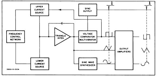
4-3. GENERAL DESCRIPTION.
4-4. The Model 3300A contains a frequency control network, two current sources, a triangle integrator, a voltage comparator multivibrator, a sine wave synthesizer and output amplifiers. (Refer to Figure 4-1
4-5. The Model 3301A Auxiliary Plug-in provides internal connections which facilitate Model 3300A operation.
4-6. The voltage comparator multivibrator, current sources and triangle integrator form the basic function generating loop. The voltage comparator multivibrator changes state at predetermined limits on the positive and negative slopes of the output of the triangular integrator. This change of state shuts off the upper current source, reverses the input to the triangle integrator. A cycle is as follows: when the amplitude of the positive slope of the triangle wave reaches the upper predetermined limit of the voltage comparator multivibrator, the multivibrator changes state. This change of state reverses the current into the triangle integrator through control of the upper current source which causes the output of the integrator to decrease. The decrease continues until the amplitude of the negative slope reaches the lower predetermined limit. At this point, the voltage comparator multivibrator changes state and again reverses the direction of current at the input of the integrator and causes the output of the
integrator to rise. This rise continues until the voltage comparator multivibrator again changes state thus completing the cycle.
4-7. The frequency control network, governed internally by the FREQUENCY Dial or externally through the FREQUENCY CONTROL, determines the amount of current in the current sources, which varies the frequency as follows: an increase or decrease in input current increases or decreases the slope of the triangle wave, respectively. (A change in direction of input current reverses the slope. ) Frequency will increase if the + and - slopes are increased, as less time is required for the + or - slope of the triangle wave to reach the predetermined limits in the voltage comparator multivibrator.
4-8. The sine wave is synthesized from the triangle wave by a nonlinear network. This network consists of resistors and diodes biased so different diodes conduct during different voltage levels of the triangle wave. These diodes, when conducting, provide additional shunt paths within the network. Each additional shunt path changes the slope of the triangle wave so that the wave is shaped to a sine wave.
4-9. The output amplifiers are dc coupled and fully floating with respect to power line ground. CHANNEL A and CHANNEL B amplifiers are identical and use a differential amplifier at the input. To maintain the same peak-to-peak amplitude regardless of function selected, the overall closed loop gain of the amplifier is varied with function selection.
Figure 4-1. Block Diagram
4-1
Section IV
4-10. The sync pulse is produced by an RC differentiating network. The negative pulse at the output is in phase with the positive crest of the sine and triangle wave.
4-11. Power Supply (Refer to Figure 6-5) can operate on either 115 or 230 volts input and delivers 3 pairs of voltages, +40V, ±26.5V, and +20V. The 40 volt supply provides power for the oven heater. The 26.5 volt supplies are regulated and the 20 volt supplies are double regulated.
4-12. Critical temperature sensitive components are housed within an oven in which the temperature is maintained at approximately 800 C (1760 F).
4-13. SCHEMATIC THEORY.
4-14. FREQUENCY CONTROL NETWORK.
4-15. (Refer to Figure 6-2) The FREQUENCY dial (R4) in conjunction with the RANGE switch (S3) provides internal frequency control. The basic frequency equation
can be expressed as F= |
i |
|
|
2C |
e out |
where i is the current to the triangle integrator, C is the triangle integrator feedback capacitor and e out is the peak-to-peak voltage of the triangle wave.
4-16. The position of the RANGE switch determines the integrating capacitor C. The FREQUENCY dial or external control voltage determines the current i. The frequency control voltage is applied to the current control transistor Al IQ5, which establishes the amount of current available to the triangle integrator from the current sources AllQ6 and AllQ7.
4-17. CURRENT SOURCES.
4-18. The state of current source A11Q6 is controlled by the voltage comparator multivibrator, and in turn, controls the direction of the current in the input of the triangle integrator. When A11Q6 is on, a current, 2 i, flows through it and divides, i into the integrator and i through current source A11Q7. When the bi-stable multivibrator changes state and gates A11Q6 off, 2 i no longer flows; however, the current through A11Q7 remains the same. Therefore, a current equal to i but opposite in direction flows from the triangle integrator input.
4-19. TRIANGLE INTEGRATOR.
4-20. The triangle integrator consists of an impedance converter A11Q8 (a field effect transistor), a differential amplifier A13Q1 and A13Q2, an emitter follower A13Q3, diode A13CR1, and the capacitive feedback network: this circuit integrates the constant current inputs into the positive and negative slopes which make up the triangle wave. The triangle wave is applied to the inputs of the output amplifiers, sine wave synthesizer and voltage comparator multivibrator.
4-21. VOLTAGE COMPARATOR MULTIVIBRATOR.
4-22. The voltage comparator multivibrator consists of a voltage comparator switching network, A14Q8, A14CR13 and A14CR14; a bi-stable multivibrator A14Q9 and Q10 and an emitter follower A14Q11. A14CR19 and
4-2
Model 3300A
R45 provide a low resistive path to ensure rapid rise and fall time of the square wave in the event the capacitance of the load is high. When the positive slope of the triangle wave reaches +20 volts, A14CR13 is turned on. A14Q9 is then turned on which turns A14Q10 off. The rise in the collector voltage of A14Q10 is coupled through emitter follower A14Q11 and through A14CR20 and A14CR21 into the emitter circuit of A11Q6, and turns it on. The output slope then becomes negative. A11Q6 remains on until the negative slope reaches zero volts. At the zero point on the negative slope A14CR14 is turned on which causes the bi-stable multivibrator to change state so that A14Q9 is now off and A14Q10 is on. The decrease in A14Q10 collector voltage gates the current source, A11Q6, off which reverses the integrator input current. The positive slope then begins increasing toward the upper limit, +20 volts. The output of the emitter follower is differentiated by A14C7 and A14R48 to provide the sync output. A negative sync pulse occurs at the crest of sine and triangular wave, see Figure 4-1.
4-23. SINE WAVE SYNTHESIZER.
4-24. (See Figure 6-2) The sine wave synthesizer comprises four control transistors, the biased diodes with associated voltage dividers, a differential amplifier A14Q5, A14Q6 and the output amplifier A14Q7. A14R17 andA14R29 adjust the operating points of the voltage dividers to minimize distortion. The diodes are biased by the four control transistors A14Q1 through A14Q4 and the voltage dividers to provide twelve different current paths in the input to the differential amplifier as the triangle wave progresses. Each slope of the triangle wave is modified in twelve steps so that the waveform appearing at the base of A14Q5 approximates a sine wave. The sine wave synthesizing network is isolated by the differential amplifier A14Q5 and A14Q6 and amplifier A14Q7.
4-25. OUTPUT AMPLIFIERS. Figure 6-4).
4-26. The etched circuit assemblies A15 and A16 are identical. CHANNEL A and CHANNEL B differ due to the -A output of CHANNEL B. The input for CHANNEL B with its function switch in -A position, A16 Pin 5, is taken from the junction of A15R20 and R21, XA15 Pin 11. The output amplifiers are variable gain amplifiers. Gain is varied by changing the amount of feedback for the different functions. The following reference designators should be prefixed by applicable assembly number. The feedback is varied by resistors R1 through R5 and R23 C8 combination, to maintain equal peak-to-peak amplitude of the various functions for a given AMPLITUDE control setting. A differential amplifier, Q1 and Q2, make up the first stage followed by two additional amplifiers Q3 and Q4. The trimmer C2 in the feedback network is used to shape the square wave. The AMPLITUDE control provides a nominal 600 ohms output impedance, independent of amplitude control setting.
Model 3300A
4-27. POWER SUPPLY (Figure 6-5).
4-28. The power supply consists of two full wave rectifiers CR1 thru CR4 and four series regulated supplies. AllCR1 provides a stable reference for the two negative regulated supplies which in turn are the references for the two positive regulated supplies. The two 20 volt supplies are double regulated. The operation of the four supplies is similar: A differential amplifier senses and amplifies any change. The change is applied through a driver stage to the series regulator which then changes its conduction to oppose the change.
4-29. Operation of the positive and negative supplies is similar. Diodes CR2 thru CR5 and CR7 thru CR9 determine the maximum current permitted to flow in the series regulating transistors. Referring to Figure 6-5, +26.5 volt supply, it can be seen that an increase in current through R5 and R6 increases the overall forward bias on the diode network CR2 thru CR5. The magnitude of this forward bias is determined by the sum of the forward biased base-emitter diode voltage of Q1 and Q2 in addition to the voltage drop across the R5-R6
Section IV
combination. When this forward bias increases to a level sufficient to allow the diodes to conduct, any increase in the collector current of Q4 will pass through the diodes and not enter the base of Q2. This, in thru, limits the maximum current in the series regulating transistors.
4-30. OVEN.
4-31. (See Figure 6-5.) The desired oven temperature is automatically maintained by a thermal control loop. The loop consists of a thermistor, a signal amplifier, a power amplifier, and the heater resistors. The operation of the loop is as follows: The resistance of RT1 (thermistor) decreases with an increase in temperature which causes the base current of A11Q9 to increase. The corresponding decrease of A11Q9 collector voltage is coupled into the base circuit of the power amplifier Q7. The collector current of Q7 then decreases which decreases the current through the heater resistors generating less heat and the temperature decreases. The response of the loop is improved by the physical location of A11R27 in close proximity to the thermistor.
4-3

Section V
Instrument Type
Electronic Counter
Distortion Analyzer
Oscilloscope
Probe 10:1
DC Voltmeter
Resistor
Resistor
Resistor
Capacitor
Variable Line Voltage
Transformer
DC Power Supply
AC Voltmeter
Printed Circuit
Extender Board
Printed Circuit
Extender Board
Table 5-1. Required Test Equipment
Required Characteristics
Range: dc to 100 kHz Accuracy: 0.1%
Range: 10 Hz to 100kHz Freq. Accuracy: +2% Sensitivity: 0.3%fullscale Input: 1 volt rms
Sensitivity: 50 mV/cm Bandwidth: dc to 30 MHz
Bandwidth: dc to 30 MHz Division Accuracy: ±2%
Accuracy: + 1% F. S. Range: 10 mV to 50 V Input Impedance: 10 MΩ
600 ohms 1/4 watt +5%
50 ohms 1/4 watt +5%
20 K 1/4 watt +5%
1 μ F 50 V
Range: 100 to 130 V
Range: 0 - 10 volts, 500 mA
Range:10 Hz to 4 MHz 30 mV to 300 V full scale
Use
Performance Checks,
Adjustment and
Calibration
Performance Checks
Performance Checks,
Adjustment
Calibration, Repair
Performance Checks,
Adjustment and
Calibration, Repair
Adjustment and
Calibration, Repair
Performance Checks
Performance Checks
Adjustment and
Calibration
Adjustment and
Calibration
Performance Checks
Performance Checks,
Adjustment and
Calibration
Adjustment and
Calibration
15 Pin |
Repair |
|
22 Pin |
Repair |
|
|
5-0 |
Model 3300A
Recommended Instrument
-hp- 5245L Electronic Counter with 5262A Plugin Time Interval Unit
-hp- Model 331A Distortion
Analyzer
-hp- 175A Oscilloscope with -hp- Plug-in 1750B Vertical Amplifier
-hp- 10001A Probe 10:1
-hp- 3440A Digital Volt-
meter with Plug-in -hp-
Model 3443A
-hp- Part No. 0730-0010
-hp- Part No. 0683-5105
-hp- Part No. 0686-2035
-hp- Part No. 0160-0859
Superior Type UCIM
-hp- 723A Power Supply
-hp- 400F/FL Voltmeter
-hp- Part No. 5060-0049
-hp- Part No. 5060-0630
Model 3300A |
Section V |
SECTION V
MAINTENANCE
5-1. INTRODUCTION.
5-2. This section contains information necessary for the proper maintenance of the -hp- Model 3300A Function Generator. The required test equipment is listed in Table 5-1. Test equipment with comparable characteristics can be substituted if recommended equipment is not available.
5-3. PERFORMANCE CHECKS.
5-4. The performance checks are front panel procedures designed to compare the -hp- Model 3300A with its specifications. (See Table 1-1). These checks may be accomplished with either the 3301A Auxiliary Plug-in or Malfunction Isolating Aid Plug (see Figure 5-7) installed in the 3300A. These operations should be completed before any attempt is made to adjust or calibrate the instrument. Allow a 30 minute warm-up period before making performance checks. If a performance check indicates that the instrument does not meet specifications refer to the applicable paragraph in the Adjustment and Calibration procedure contained in this Section. (See Table 5-5).
5-5. DIAL ACCURACY.
a.Test equipment required: Frequency Counter (-hp- Model 5245L).
b.Connect CHANNEL A OUTPUT to the
frequency counter and set the 3300A
control as follows: |
|
CHANNEL A function switch |
......... SINE |
CHANNEL A AMPLITUDE ............ |
mid |
|
position |
c.Check frequency with dial at 1 and 10 for each position of RANGE switch.
d.Accuracy should be * 1% of maximum dial setting (one minor division) on X. 01 through X1K ranges, and ± 2% of maximum dial setting (two minor divisions) on X10K range.
5-6. Since the specification gives % of maximum dial setting (full scale, the accuracy will always be + 1 or 2 minor divisions at any point on the dial.
5-7. DISTORTION CHECK.
a.Test equipment required: Distortion Analyzer (-hp- Model 331A).
b.Connect the OUTPUT of CHANNEL A to distortion analyzer and set 3300A controls
as follows: |
|
FREQUENCY dial ...................... |
10 |
RANGE switch............................ |
X1K |
CHANNEL A function switch ...... |
SINE |
CHANNEL A AMPLITUDE |
|
control................................. |
mid position |
c.Distortion should be less than 1%.
d. Position the RANGE switch to X10K. Distortion should be less than 3%.
NOTE
The sine function is electronically synthesized from the triangle function. Satisfactory performance of Distortion Check assures symmetry and triangle linearity.
5-8. FREQUENCY RESPONSE:
5-9. Test equipment required: Oscilloscope (-hp- Model 175/1750B).
a.Set up convenient reference level on oscilloscope at 1 kHz.
b.Vary frequency over the entire range except X10K. Amplitude should vary < ± 1%.
c.Vary frequency over the X10K range. Amplitude should vary < + 3%.
5-10. MAXIMUM OUTPUT LEVEL, NO LOAD.
a.Test equipment required: Oscilloscope (-hp- Model 175A/1750B).
b.Connect the OUTPUT of CHANNEL A to Oscilloscope and set 3300A controls as follows:
CHANNEL A function switch...... |
SQUARE |
CHANNEL A AMPLITUDE......... |
Max. CW |
c.The peak-to peak voltage should be > 35 volts over entire frequency range.
5-11. Repeat 5-10 above with CHANNEL A function switch set to SINE and TRIANGLE. The minimum peak- to-peak voltage should remain 35 volts.
5-12. Repeat 5-10 and 5-11 on CHANNEL B.
5-13. MAXIMUM OUTPUT LEVEL, LOADED.
a.Test equipment required: Oscilloscope (-hp- Model 175A/1750B), 600 ohm, and 50 ohm resistor, see Table 5-1.
b.Connect OUTPUT of CHANNEL A and 600 ohm resistor as shown in Figure 5-1. Set the 3300A controls as follows:
FREQUENCY dial................... |
10 |
RANGE switch ........................ |
X100 |
CHANNEL A AMPLITUDE...... |
|
control ............................. |
Max. CW |
CHANNEL A function switch... |
SQUARE |
c.Peak-to-peak voltage should be > 15 volts.
5-1
Section V |
Model 3300A |
|
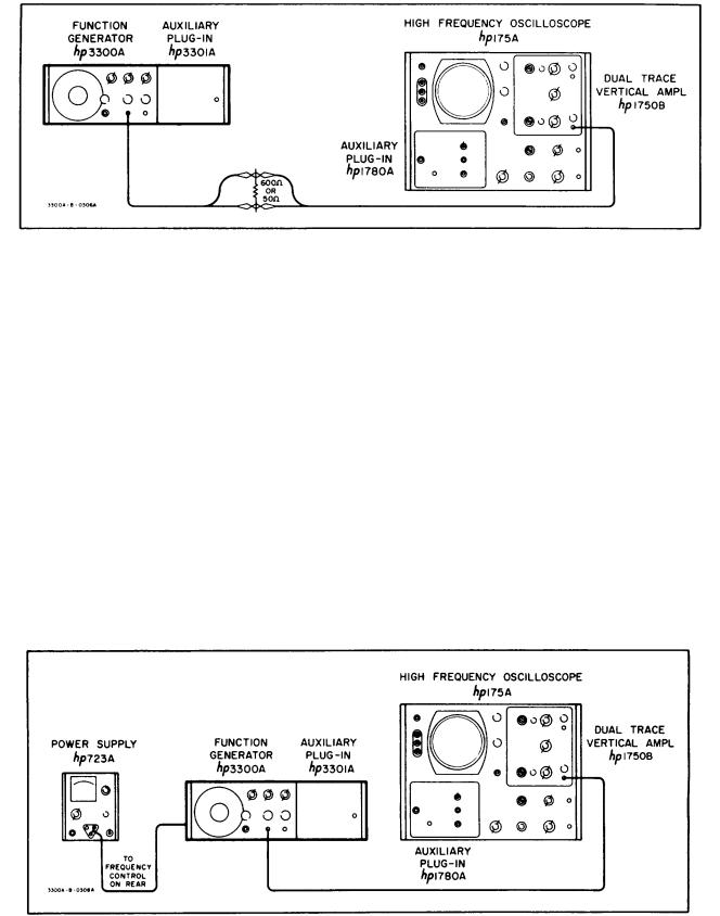
Figure 5-1. 600 ohm or 50 ohm Load Output Test Setup |
||
5-14. |
Repeat 5-13 on CHANNEL |
B. Limit should |
5-18. SYNC OUTPUT. |
remain > 15 volts peak-to-peak. |
|
a. Test equipment required: Oscilloscope (-hp- |
|
5-15. |
Repeat 5-13 and 5-14 |
except load the |
Model 175A/1750B) and 10:1 Probe (-hp- |
instrument with the 50 ohm resistor. |
CHANNEL A and |
Model 10001A). |
|
CHANNEL B voltage output should be > 2 volts peak-to- |
b. Connect SYNC OUTPUT to oscilloscope |
||
peak. |
|
|
and set 3300A controls as follows: |
|
|
|
|
FREQUENCY dial...................... |
10 |
5-16. |
SQUARE WAVE RESPONSE. |
|
RANGE switch ........................... |
X1K |
|
a. Test equipment required: Oscilloscope (-hp- |
c. Pulse should be > 10 volts peak-to-peak |
||
|
Model 175A/1750B) and 10:1 Probe (-hp- |
and < 5 microsecond duration. |
||
|
Model 10001A). |
|
5-19. REMOTE FREQUENCY CONTROL CHECK. |
|
|
b. Connect CHANNEL A OUTPUT without a |
a. Test equipment required: DC Power Supply |
||
|
load to the oscilloscope using the 10:1 |
(-hp- Model 723A) and Oscilloscope (-hp- |
||
|
Probe, and set the 3300A controls as |
Model 175A/1750B). |
|
|
|
follows: |
|
CAUTION |
|
|
CHANNEL A function ................. |
SQUARE |
VOLTAGE APPLIED TO FREQUENCY |
|
|
FREQUENCY dial ...................... |
10 |
CONTROL BNC SHOULD BE LIMITED |
|
|
RANGE switch............................ |
X10K |
TO A VALUE BETWEEN 0 AND |
|
|
c. Verify: Rise and fall time |
<250 nano sec. |
NEGATIVE 15 VOLTS. VOLTAGES |
|
|
Sag |
<1% |
OUTSIDE THIS RANGE |
WILL |
|
Overshoot (full output) <5% |
DAMAGE THE INSTRUMENT. |
|
|
|
Symmetry error |
<1% |
|
|
5-17 |
Repeat 5-16 on CHANNEL B. |
|
|
|
Figure 5-2. Remote Frequency Control Test Setup
5-2
 Loading...