


 Loading...
User’s Guide
Part Number 33120-90005
August 1997
For Safety information, Warranties, and Regulatory information, see the pages behind the Index.
©Copyright Hewlett-Packard Company 1994, 1997 All Rights Reserved.
HP 33120A
Function Generator /
Arbitrary Waveform Generator

Note: Unless otherwise indicated, this manual applies to all Serial Numbers.
The HP 33120A is a high-performance 15 MHz synthesized function generator with built-in arbitrary waveform capability. Its combination of bench-top and system features makes this function generator a versatile solution for your testing requirements now and in the future.
Convenient bench-top features
∙10 standard waveforms
∙Built-in 12-bit 40 MSa/s arbitrary waveform capability
∙Easy-to-use knob input
∙Highly visible vacuum-fluorescent display
∙Instrument state storage
∙Portable, ruggedized case with non-skid feet
Flexible system features
∙Four downloadable 16,000-point arbitrary waveform memories
∙HP-IB (IEEE-488) interface and RS-232 interface are standard
∙SCPI (Standard Commands for Programmable Instruments) compatibility
∙Optional HP 34811A BenchLink/Arb Waveform Generation Software for Microsoft®WindowsTM
HP 33120A
Function Generator /
Arbitrary Waveform Generator

The Front Panel at a Glance
1 |
Function / Modulation keys |
5 |
Recall / Store instrument state key |
2 |
Menu operation keys |
6 |
Enter Number key |
3 |
Waveform modify keys |
7 |
Shift / Local key |
4 |
Single / Internal Trigger key |
8 |
Enter Number “units” keys |
|
(Burst and Sweep only) |
|
|
2
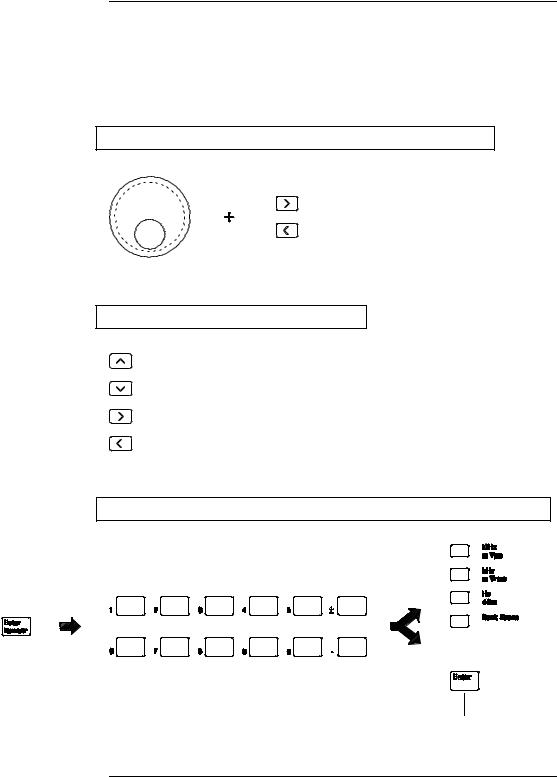
Front-Panel Number Entry
You can enter numbers from the front-panel using one of three methods.
Use the knob and the arrow keys to modify the displayed number.
Use the arrow keys to edit individual digits.
Increments the flashing digit.
Decrements the flashing digit.
Moves the flashing digit to the right.
Moves the flashing digit to the left.
Use the “Enter Number” mode to enter a number with the appropriate units.
Use “Enter” for those operations that do not require units to be specified (AM Level, Offset, % Duty, and Store/Recall State).
3
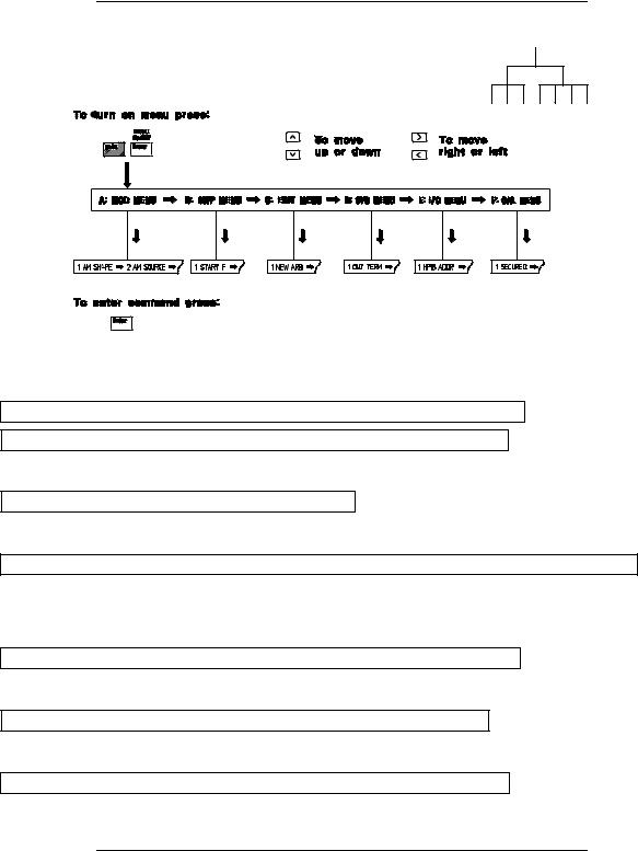
The Front-Panel Menu at a Glance
The menu is organized in a top-down tree structure with three levels.
A: MODulation MENU
1: AM SHAPE ’ 2: AM SOURCE ’ 3: FM SHAPE ’ 4: BURST CNT ’ 5: BURST RATE ’
’ 6: BURST PHAS ’ 7: BURST SRC ’ 8: FSK FREQ ’ 9: FSK RATE ’ 10: FSK SRC
B:SWP (Sweep) MENU
1:START F ’ 2: STOP F ’ 3: SWP TIME ’ 4: SWP MODE
C:EDIT MENU*
1: NEW ARB ’ [ 2: POINTS ] ’ [ 3: LINE EDIT ] ’ [ 4: POINT EDIT ] ’ [ 5: INVERT ] ’ [ 6: SAVE AS ] ’ 7: DELETE
*The commands enclosed in square brackets ( [ ] ) are “hidden” until you make a selection from the NEW ARB command to initiate a new edit session.
D: SYStem MENU
1: OUT TERM ’ 2: POWER ON ’ 3: ERROR ’ 4: TEST ’ 5: COMMA ’ 6: REVISION
E: Input / Output MENU
1: HPIB ADDR ’ 2: INTERFACE ’ 3: BAUD RATE ’ 4: PARITY ’ 5: LANGUAGE
F:CALibration MENU*
1:SECURED ’ [ 1: UNSECURED ] ’ [ 2: CALIBRATE ] ’ 3: CAL COUNT ’ 4: MESSAGE
*The commands enclosed in square brackets ( [ ] ) are “hidden” unless the function generator is UNSECURED for calibration.
4

Display Annunciators
Adrs |
Function generator is addressed to listen or talk over a remote interface. |
Rmt |
Function generator is in remote mode (remote interface). |
Trig |
Function generator is waiting for a single trigger or external trigger (Burst, Sweep). |
AM |
AM modulation is enabled. |
FM |
FM modulation is enabled. |
Ext |
Function generator is set for an external modulation source (AM, FSK, Burst). |
FSK |
FSK (frequency-shift keying) modulation is enabled. |
Burst |
Burst modulation is enabled. |
Swp |
Sweep mode is enabled. |
ERROR |
Hardware or remote interface command errors are detected. |
Offset |
The waveform is being output with an offset voltage. |
Shift |
“Shift” key has been pressed. Press “Shift” again to turn off. |
Num |
“Enter Number” mode is enabled. Press “Shift-Cancel” to disable. |
Arb |
Arbitrary waveform function is enabled. |
|
Sine waveform function is enabled. |
|
Square waveform function is enabled. |
|
Triangle waveform function is enabled. |
|
Ramp waveform function is enabled. |
To review the display annunciators, hold down the Shift key as you turn on the function generator.
5
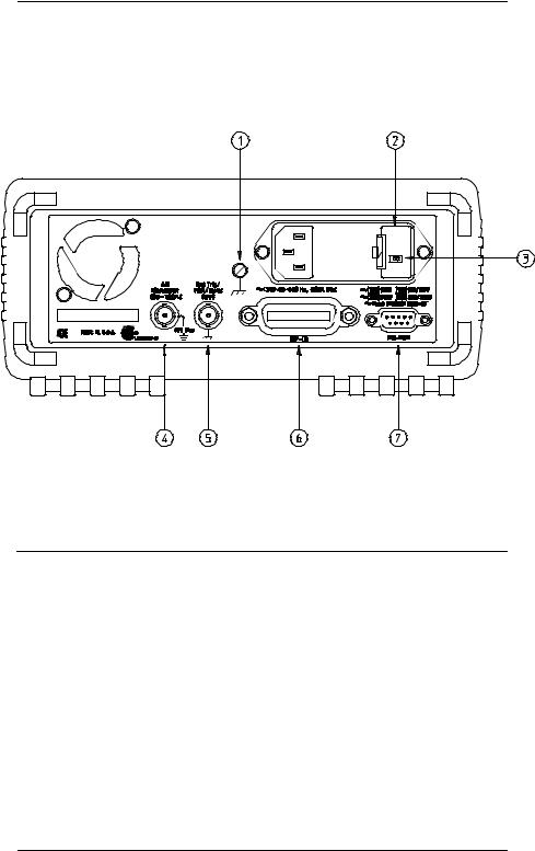
The Rear Panel at a Glance
1 |
Chassis ground |
5 |
External Trigger / FSK / Burst modulation |
2 |
Power-line fuse-holder assembly |
|
input terminal |
3 |
Power-line voltage setting |
6 |
HP-IB (IEEE-488) interface connector |
4 |
AM modulation input terminal |
7 |
RS-232 interface connector |
Use the front-panel Input / Output Menu to:
∙Select the HP-IB or RS-232 interface (see chapter 4).
∙Set the HP-IB bus address (see chapter 4).
∙Set the RS-232 baud rate and parity (see chapter 4).
6

In This Book
Quick Start Chapter 1 prepares the function generator for use and helps you get familiar with a few of its front-panel features.
Front-Panel Menu Operation Chapter 2 introduces you to the front-panel menu and describes some of the function generator’s menu features.
Features and Functions Chapter 3 gives a detailed description of the function generator’s capabilities and operation. You will find this chapter useful whether you are operating the function generator from the front panel or over the remote interface.
Remote Interface Reference Chapter 4 contains reference information to help you program the function generator over the remote interface.
Error Messages Chapter 5 lists the error messages that may appear as you are working with the function generator. Each listing contains enough information to help you diagnose and solve the problem.
Application Programs Chapter 6 contains several remote interface application programs to help you develop programs for your application.
Tutorial Chapter 7 discusses the fundamentals of signal generation and modulation techniques.
Specifications Chapter 8 lists the function generator’s specifications.
For information on using the Phase-Lock Option for the HP 33120A, refer to the User’s and Service Guide included with the Option 001.
If you have questions relating to the operation of the HP 33120A, call 1-800-452-4844 in the United States, or contact your nearest Hewlett-Packard Sales Office.
If your HP 33120A fails within three years of purchase, HP will repair or replace it free of charge. Call 1-800-258-5165 (“Express Exchange”) in the United States, or contact your nearest Hewlett-Packard Sales Office.
7

Contents
Chapter 1 Quick Start
To prepare the function generator for use 15 If the function generator does not turn on 16 To adjust the carrying handle 18
To set the output frequency 19 To set the output amplitude 20 To set a dc offset voltage 21 To set the duty cycle 22
To output a stored arbitrary waveform 23 To output a dc voltage 24
To store the instrument state 25
To rack mount the function generator 27
Chapter 2 Front-Panel Menu Operation
Front-panel menu reference 31 A front-panel menu tutorial 33
To select the output termination 40 To output a modulated waveform 41 To output an FSK waveform 44
To output a burst waveform 47 To output a frequency sweep 49 To trigger a burst or sweep 51
To turn off the comma separator 52
Chapter 3 Features and Functions
Output Configuration 55
Amplitude Modulation (AM) 71
Frequency Modulation (FM) 76
Burst Modulation 81
Frequency-Shift Keying (FSK) Modulation 90
Frequency Sweep 94
Triggering 98
Arbitrary Waveforms 103
System-Related Operations 109
Remote Interface Configuration 114
Calibration Overview 118
Power-On and Reset State 123
Contents
9

Contents
Contents
Chapter 4 Remote Interface Reference
SCPI Command Summary 127 Simplified Programming Overview 136 Using the APPLy Command 138 Output Configuration Commands 145 AM Modulation Commands 154
FM Modulation Commands 157 Burst Modulation Commands 160
Frequency-Shift Keying (FSK) Commands 167 Frequency Sweep Commands 170
Arbitrary Waveform Commands 174 Triggering 186
System-Related Commands 188 Calibration Commands 193 RS-232 Interface Configuration 195 RS-232 Interface Commands 200 The SCPI Status Registers 201 Status Reporting Commands 209
An Introduction to the SCPI Language 211 Halting an Output in Progress 216
To set the HP-IB address 217
To select the remote interface 218 To set the baud rate 219
To set the parity 220
SCPI Conformance Information 221 IEEE-488 Conformance Information 225
Chapter 5 Error Messages
Execution Errors 229
Self-Test Errors 237
Calibration Errors 238
Arbitrary Waveform Errors 240
10
Contents
Chapter 6 Application Programs
HP BASIC Programs 244
C Language Programs 244 QuickBASIC Language Programs 247 Using the APPLy Command 248 Using the Low-Level Commands 252
Downloading an Arbitrary Waveform over HP-IB 255 Using the Status Registers 261
Downloading an Arbitrary Waveform over RS-232 267
Chapter 7 Tutorial
Direct Digital Synthesis 273
Signal Imperfections 276
Creating Arbitrary Waveforms 278
Output Amplitude Control 280
Floating Signal Generators 282
Attributes of AC Signals 283
Modulation 287
Chapter 8 Specifications
Frequency Characteristics 298
Sinewave Spectral Purity 298
Signal Characteristics 298
Output Characteristics 298
Modulation Characteristics 299
Frequency Sweep 299
System Characteristics 299
General Specifications 300
Product Dimensions 301
Index 303
Declaration of Conformity 309
Contents
11

1
1
Quick Start

Quick Start
One of the first things you will want to do with your function generator is to become acquainted with its front panel. We have written the exercises in this chapter to prepare the function generator for use and help you get familiar with some of the front-panel operations.
The front panel has two rows of keys to select various functions and operations. Most keys have a shifted function printed in blue above
the key. To perform a shifted function, press Shift (the Shift annun-
ciator will turn on). Then, press the key that has the desired label above it. For example, to select the AM (amplitude modulation)
function, press Shift AM |
(the shifted version of the |
key). |
If you accidentally press |
Shift , just press it again to turn off the |
|
Shift annunciator. |
|
|
Most keys also have a number printed in green next to the key.
To enable the number mode, press Enter Number (the Num annunciator
will turn on). Then, press the keys that have the desired numbers printed next to them. For example, to select the number “10”,
press Enter Number 1 0 |
(next to the |
and Recall keys). |
If you accidentally press |
Enter Number |
, just press Shift Cancel |
to turn off the Num annunciator. |
|
|
14

Chapter 1 Quick Start
To prepare the function generator for use
1
To prepare the function generator for use
The following steps help you verify that the function generator is ready for use.
1 Check the list of supplied items.
Verify that you have received the following items with your function generator. If anything is missing, contact your nearest Hewlett-Packard Sales Office.
One power cord.
This User’s Guide.
One Service Guide.
One folded Quick Reference card.
Certificate of Calibration.
2Connect the power cord and turn on the function generator.
The front-panel display will light up while the function generator performs its power-on self-test. The HP-IB bus address is displayed.
Notice that the function generator powers up in the sine wave function at 1 kHz with an amplitude of 100 mV peak-to-peak (into a 50Ω termination).
To review the power-on display with all annunciators turned on, hold down Shift as you turn on the function generator.
3Perform a complete self test.
The complete self-test performs a more extensive series of tests than those performed at power-on. Hold down Shift as you press the Power switch to turn on the function generator; hold down the key for more than 5 seconds. The self-test will begin when you release the key.
If the self-test is successful, “PASS” is displayed on the front panel. If the self-test is not successful, “FAIL” is displayed and the ERROR annunciator turns on. See the Service Guide for instructions on returning the function generator to Hewlett-Packard for service.
15

Chapter 1 Quick Start
If the function generator does not turn on
If the function generator does not turn on
Use the following steps to help solve problems you might experience when turning on the function generator. If you need more help, see the Service Guide for instructions on returning the function generator to Hewlett-Packard for service.
1Verify that there is ac power to the function generator.
First, verify that the function generator’s Power switch is in the
“On” position. Also, make sure that the power cord is firmly plugged into to the power module on the rear panel. You should also make sure that the power source you plugged the function generator into is energized.
2Verify the power-line voltage setting.
The line voltage is set to the proper value for your country when the function generator is shipped from the factory. Change the voltage setting if it is not correct. The settings are: 100, 120, 220, or 240 Vac (for 230 Vac operation, use the 220 Vac setting).
See the next page if you need to change the line-voltage setting.
3Verify that the power-line fuse is good.
The function generator is shipped from the factory with a 500 mAT fuse installed. This is the correct fuse for all line voltages.
See the next page if you need to change the power-line fuse.
To replace the 500 mAT fuse, order HP part number 2110-0458.
16

Chapter 1 Quick Start
If the function generator does not turn on
1
1Remove the power cord. Remove the fuse-holder assembly from the rear panel.
2Remove the line-voltage selector from the assembly.
3Rotate the line-voltage selector until the correct voltage appears in the window.
Fuse: 500 mAT (for all line voltages)
HP Part Number: 2110-0458
4Replace the fuse-holder assembly in the rear panel.
100, 120, 220 (230), or 240 Vac
Verify that the correct line voltage is selected and the power-line fuse is good.
17
Chapter 1 Quick Start
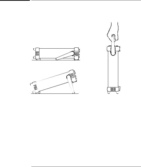
To adjust the carrying handle
To adjust the carrying handle
To adjust the position, grasp the handle by the sides and pull outward. Then, rotate the handle to the desired position.
Bench-top viewing positions |
Carrying position |
18

Freq
Enter Number
1 
 .
. 
 2
2
MHz m Vpp
Chapter 1 Quick Start
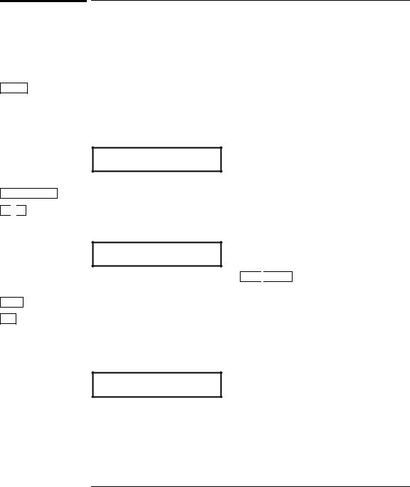
To set the output frequency
1
To set the output frequency
At power-on, the function generator outputs a sine wave at 1 kHz with an amplitude of 100 mV peak-to-peak (into a 50Ω termination).
The following steps show you how to change the frequency to 1.2 MHz.
1Enable the frequency modify mode.
The displayed frequency is either the power-on value or the previous frequency selected. When you change functions, the same frequency is used if the present value is valid for the new function.
1.000,000,0 KHz
2Enter the magnitude of the desired frequency.  1
1
Notice that the Num annunciator turns on and “ENTER NUM” flashes on the display, indicating that the number mode is enabled.
1.2
To cancel the number mode, press Shift 
 Cancel .
3Set the units to the desired value.
The units are selected using the arrow keys on the right side of the front panel. As soon as you select the units, the function generator outputs the waveform with the displayed frequency. To turn off the flashing digit, move the cursor to the left of the display using the arrow keys.
1.200,000,0 MHz
1You can also use the knob and arrow keys to enter a number.
See “Front-Panel Number Entry” on page 3 for more information.
19
Ampl
Enter Number
5 
 0
0
Shift
kHz
m Vrms
Chapter 1 Quick Start
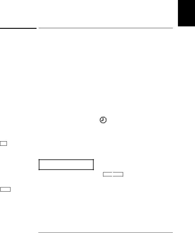
To set the output amplitude
To set the output amplitude
At power-on, the function generator outputs a sine wave with an amplitude of 100 mV peak-to-peak (into a 50Ω termination).
The following steps show you how to change the amplitude to 50 mVrms.
1Enable the amplitude modify mode.
The displayed amplitude is either the power-on value or the previous amplitude selected. When you change functions, the same amplitude is used if the present value is valid for the new function.
100.0 mVPP
2Enter the magnitude of the desired amplitude.  1
1
Notice that the Num annunciator turns on and “ENTER NUM” flashes on the display, indicating that the number mode is enabled.
50
To cancel the number mode, press Shift 
 Cancel .
3Set the units to the desired value.
The units are selected using the arrow keys on the right side of the front panel. As soon as you select the units, the function generator outputs the waveform with the displayed amplitude. To turn off the flashing digit, move the cursor to the left of the display using the arrow keys.
50.00 mVRMS
1You can also use the knob and arrow keys to enter a number.
See “Front-Panel Number Entry” on page 3 for more information.
20

Chapter 1 Quick Start
To set a dc offset voltage
1
To set a dc offset voltage
At power-on, the function generator outputs a sine wave with a dc offset voltage of 0 volts (into a 50Ω termination). The following steps show you how to change the offset to –1.5 mVdc.
Offset |
1 Enable the offset modify mode. |
The displayed offset voltage is either the power-on value or the previous offset selected. When you change functions, the same offset is used if the present value is valid for the new function.
Enter Number
± 
 1
1 
 .
. 
 5
5
Shift
kHz
m Vrms
+0.000 VDC
2 Enter the magnitude of the desired offset. |
1 |
|
Notice that the Num annunciator turns on and “ENTER NUM” flashes on the display, indicating that the number mode is enabled. Notice that ± toggles the displayed value between + and – .
-1.5
To cancel the number mode, press Shift 
 Cancel .
3Set the units to the desired value.
At this point, the function generator outputs the waveform with the displayed offset. Notice that the Offset annunciator turns on, indicating that the waveform is being output with an offset. The annunciator will turn on when the offset is any value other than 0 volts. To turn off the flashing digit, move the cursor to the left of the display using the arrow keys.
-01.50 mVDC
1You can also use the knob and arrow keys to enter a number.
See “Front-Panel Number Entry” on page 3 for more information.
21
Chapter 1 Quick Start
To set the duty cycle
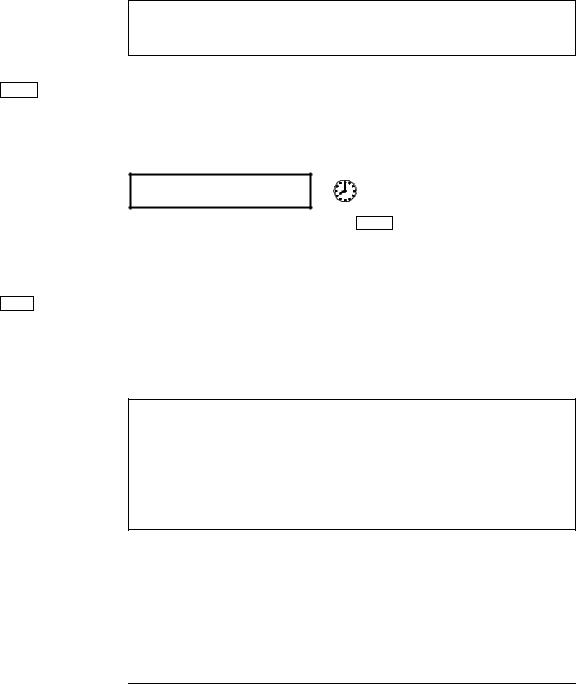
To set the duty cycle
Applies only to square waves. At power-on, the duty cycle for square waves is 50%. You can adjust the duty cycle for a square waveform from 20% to 80%, in increments of 1% (for frequencies above 5 MHz, the range is 40% to 60%). The following steps show you how to change the duty cycle to 45%.
|
|
|
|
1 |
Select the square wave function. |
|
|
|
|
|
|||
|
|
|
|
|
Notice that the |
annunciator turns on, indicating that the |
|
|
|
|
|
square wave function is enabled. |
|
|
|
|
|
|
|
|
Shift |
|
% Duty |
2 |
Enable the duty cycle modify mode. |
||
|
|
|
|
|||
|
|
|
|
|
The displayed duty cycle is either the power-on value or the previous |
|
|
|
|
|
|
value selected. |
|
Enter Number
4 
 5
5
Enter
50 % DUTY
This message appears on the display for approximately 10 seconds. Repeat this step as needed.
3Enter the desired duty cycle.  1
1
Notice that the Num annunciator turns on and “ENTER NUM” flashes on the display, indicating that the number mode is enabled.
45
To cancel the number mode, press Shift 
 Cancel .
4 Output the waveform with the displayed duty cycle.
45 % DUTY
1You can also use the knob and arrow keys to enter a number.
See “Front-Panel Number Entry” on page 3 for more information.
22

Chapter 1 Quick Start
To output a stored arbitrary waveform
1
To output a stored arbitrary waveform
There are five built-in arbitrary waveforms stored in non-volatile memory for your use. You can output these waveforms directly from non-volatile memory. The following steps show you how to output an
“exponential rise” waveform from memory.
Shift |
|
Arb List |
1 Display the list of arbitrary waveforms. |
The list contains the five built-in arbitrary waveforms (sinc, negative ramp, exponential rise, exponential fall, and cardiac). The list may also contain up to four user-defined arbitrary waveform names. The first choice on this level is “SINC”.
SINC
This message appears on the display for approximately 10 seconds.
Repeat this step as needed.
> 
 >
>
Enter
2Move across to the EXP_RISE choice.  1
1
EXP_RISE
3Select and output the displayed arbitrary waveform.
Notice that the Arb annunciator turns on, indicating that the output is an arbitrary waveform. The waveform is output using the present settings for frequency, amplitude, and offset unless you change them.
The selected waveform is now assigned to the Arb key. Whenever you press this key, the selected arbitrary waveform is output.
1You can also use the knob to scroll left or right through the choices in the list.
See “Front-Panel Number Entry” on page 3 for more information.
23

Enter Number
1 
 5
5 
 5
5
Shift
kHz
m Vrms
Chapter 1 Quick Start
To output a dc voltage
To output a dc voltage
In addition to generating waveforms, you can also output a dc voltage in the range ± 5 Vdc (into a 50Ω termination). The following steps show you how to output +155 mVdc.
1 Press the Offset key and hold it down for more than 2 seconds.
To enter the dc voltage mode, press the Offset key or any key in the top row of function keys and hold it down for more than 2 seconds. The displayed voltage is either the power-on value or the previous offset voltage selected.
DCV
+0.000 VDC
2Enter the magnitude of the desired voltage.  1
1
Notice that the Num annunciator turns on and “ENTER NUM” flashes on the display, indicating that the number mode is enabled.
155
To cancel the number mode, press Shift 
 Cancel .
3Set the units to the desired value.
At this point, the function generator outputs the displayed dc voltage. Notice that the Offset annunciator turns on (all other annunciators are off), indicating that a dc voltage is being output. The annunciator will turn on when the offset is any value other than 0 volts.
+155.0 mVDC
1You can also use the knob and arrow keys to enter a number.
See “Front-Panel Number Entry” on page 3 for more information.
24
Chapter 1 Quick Start
To store the instrument state
1
|
|
|
To store the instrument state |
|||
|
|
|
You can store up to three different instrument states in non-volatile |
|||
|
|
|
memory. This enables you to recall the entire instrument configuration |
|||
|
|
|
with just a few key presses from the front panel. The following steps |
|||
|
|
|
show you how to store and recall a state. |
|||
|
|
|
1 Set up the function generator to the desired configuration. |
|||
|
|
|
The state storage feature “remembers” the function, frequency, |
|||
|
|
|
amplitude, dc offset, duty cycle, as well as any modulation parameters. |
|||
|
|
|
|
|
||
Shift |
|
Store |
2 Turn on the state storage mode. |
|||
|
|
|
Three memory locations (numbered 1, 2, and 3) are available to store |
|||
|
|
|
instrument configurations. The instrument configuration is stored in |
|||
|
|
|
non-volatile memory and is remembered when power has been off. |
|||
|
|
|
|
|
|
|
|
|
|
|
STORE 1 |
|
|
|
|
|
|
|
|
|
|
|
|
|
|
|
|
|
|
|
|
|
|
|
Enter
This message appears on the display for approximately 10 seconds. Repeat this step as needed.
3Store the instrument state in memory location “2”.  1
1
Use the up and down arrow keys to select the memory location.
STORE 2
To cancel the store operation, press Shift 
 Store again or let the display time-out after 10 seconds.
4Save the instrument state.
The instrument state is now stored. To recall the stored state, turn to the next page.
1You can also use the knob or “enter number” mode to enter a memory location. See “Front-Panel Number Entry” on page 3 for more information.
25
Recall
Enter
Chapter 1 Quick Start
To store the instrument state
To verify that the state was stored properly, you can turn the power off before recalling the state.
5Recall the stored instrument state.
To recall the stored state, you must use the same memory location used previously to store the state. Use the up and down arrow keys to change the displayed storage location.
RECALL 2
To cancel the restore operation, press Recall again.
This message appears on the display for approximately 10 seconds. Repeat this step as needed.
6Restore the instrument state.
The function generator should now be configured in the same state as when you stored the setup on the previous page.
When power is turned off, the function generator automatically stores its state in memory location “0”. You can recall the power-down state, but you cannot store the state to location “0” from the front panel.
Use the POWER ON LAST STATE command in the SYS MENU to automatically recall the power-down state when power is turned on. See chapter 2 for more information on using the front-panel menus.
26
Chapter 1 Quick Start
To rack mount the function generator
1
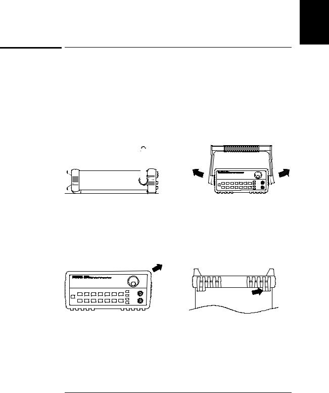
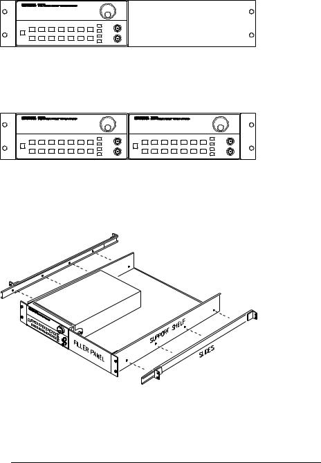
To rack mount the function generator
You can mount the function generator in a standard 19-inch rack cabinet using one of three optional kits available. Instructions and mounting hardware are included with each rack-mounting kit.
Any HP System II instrument of the same size can be rack-mounted beside the HP 33120A Function Generator.
Remove the carrying handle, and the front and rear rubber bumpers, before rack-mounting the function generator.
To remove the handle, rotate it to the vertical position and pull the ends outward.
Front |
Rear (bottom view) |
To remove the rubber bumper, stretch a corner and then slide it off.
27
Chapter 1 Quick Start
To rack mount the function generator
To rack mount a single instrument, order adapter kit 5063-9240.
To rack mount two instruments side-by-side, order lock-link kit 5061-9694 and flange kit 5063-9212.
To install one or two instruments in a sliding support shelf, order shelf 5063-9255, and slide kit 1494-0015 (for a single instrument, also order filler panel 5002-3999).
28

2
2
Front-Panel
Menu Operation

Front-Panel Menu Operation
By now you should be familiar with some of the basic features of the front panel. Chapter 1 shows you how to prepare the function generator for use and describes a few of the front-panel features. If you are not familiar with this information, we recommend that you read chapter 1,
“Quick Start,” starting on page 13.
Chapter 2 introduces you to the use of the front-panel menu. This chapter does not give a detailed description of every front-panel key or menu operation. It does, however, give you a good overview of the front-panel menu and many front-panel operations. See chapter 3 “Features and Functions,” starting on page 53, for a complete discussion of the function generator’s capabilities and operation.
If you purchased the Phase-Lock Option for the HP 33120A, an additional menu (G: PHASE MENU) is available from the front panel.
For information on using the Phase-Lock Option, refer to the User’s and Service Guide included with Option 001.
30

Chapter 2 Front-Panel Menu Operation
Front-panel menu reference
Front-panel menu reference
A: MODulation MENU
|
|
2 |
|
1: AM SHAPE ’ 2: AM SOURCE ’ 3: FM SHAPE ’ 4: BURST CNT ’ 5: BURST RATE ’ |
|||
|
|||
|
|
|
|
|
|
|
|
’ 6: BURST PHAS ’ 7: BURST SRC ’ 8: FSK FREQ ’ 9: FSK RATE ’ 10: FSK SRC |
|
|
|
|
|
|
|
1:AM SHAPE
2:AM SOURCE
3:FM SHAPE
4:BURST CNT
5:BURST RATE
6:BURST PHAS
7:BURST SRC
8:FSK FREQ
9:FSK RATE
10:FSK SRC
Selects the shape of the AM modulating waveform. Enables or disables the internal AM modulating source. Selects the shape of the FM modulating waveform.
Sets the number of cycles per burst (1 to 50,000 cycles). Sets the burst rate in Hz for an internal burst source.
Sets the starting phase angle of a burst (-360 to +360 degrees). Selects an internal or external gate source for burst modulation. Sets the FSK “hop” frequency.
Selects the internal FSK rate between the carrier and FSK frequency. Selects an internal or external source for the FSK rate.
B: SWP (Sweep) MENU
1: START F ’ 2: STOP F ’ 3: SWP TIME ’ 4: SWP MODE
1: START F |
Sets the start frequency in Hz for sweeping. |
2: STOP F |
Sets the stop frequency in Hz for sweeping. |
3: SWP TIME |
Sets the repetition rate in seconds for sweeping. |
4: SWP MODE |
Selects linear or logarithmic sweeping. |
C: EDIT MENU *
1: NEW ARB ’ [ 2: POINTS ] ’ [ 3: LINE EDIT ] ’ [ 4: POINT EDIT ] ’ [ 5: INVERT ] ’ [ 6: SAVE AS ] ’ 7: DELETE
1: NEW ARB |
Initiates a new arb waveform or loads the selected arb waveform. |
2: POINTS |
Sets the number of points in a new arb waveform (8 to 16,000 points). |
3: LINE EDIT |
Performs a linear interpolation between two points in the arb waveform. |
4: POINT EDIT |
Edits the individual points of the selected arb waveform. |
5: INVERT |
Inverts the selected arb waveform by changing the sign of each point. |
6: SAVE AS |
Saves the current arb waveform in non-volatile memory. |
7: DELETE |
Deletes the selected arb waveform from non-volatile memory. |
*The commands enclosed in square brackets ( [ ] ) are “hidden” until you make a selection from the NEW ARB command to initiate a new edit session.
31
Loading...