


HP LaserJet 3000, 3600 and 3800 Series Printers - Part Numbers Not Found in the Service Manual
Introduction
The following part numbers are not in the Service Manual.
Part Numbers
Part Description |
Part Number |
|
|
|
|
Duplex ETB |
RM1-2752-000CN |
|
|
|
|
Electronic transfer belt (ETB) simplex models |
RM1-2759-000CN |
|
|
|
|
Plate Lock Release/Tray 2 Lift Tab |
RC1-6833-020CN |
|
|
|
|
Relay PCB |
RM1-2632-000CN |
|
NOTE: This part for CLJ 3600 and 3800 |
NOTE: This part for CLJ 3600 and 3800 |
|
models only. |
models only. |
|
|
|
|
Tray 2 cassette pickup roller |
RM1-2702-000CN |
|
|
|
|
|
Q5982-67925 |
|
Toner cartridge lock kit |
NOTE: Please see Service Advisory |
|
|
c00775200 |
|
|
|
|
Tension spring (Figure 7-5, item 4 in Service |
RC1-6634-000CN |
|
Manual) |
||
|
||
Main drive assembly |
RM1-2751-000CN |
|
|
|
For HP and Channel Partner Internal Use
SUPPORT COMMUNICATION - SERVICE ACTION ADVISORY
Document ID: c00775200
Version: 5
HP Color LaserJet 3000, 3600 and 3800 Printers - Cartridge Lock Replacement Procedure
Service Coverage Notice:
Unless otherwise specified, HP is responsible for part and/or labor costs associated with products that are under HP warranty at the time of service.
Release Date: 2006-12-11
Last Updated: 2006-12-11
DESCRIPTION
The HP Color LaserJet 3800 Service Manual currently does not have instructions for replacing the main drive assembly or the cartridge locks. The cartridge locks are currently breaking and, until June 2006, the only solution was to replace the unit.
NOTE: This Service Action Advisory supercedes Service Advisory c00673707. Please use this Service Action Advisory for repairs after 04-Dec-2006.
A video of the replacement procedure is available: ftp://ftp.hp.com/pub/softlib/software8/COL17123/lj- 45472-1/tonerlock3.wmv
SCOPE
The products indicated in the table below are affected by this advisory.
|
Product # |
|
Product Name |
|
Service Note Number for Reimbursement |
|
|
|
|
|
|||
|
|
|
|
|
|
|
|
Product # |
|
Product Name |
|
Service Note Number for Reimbursement |
|
|
|
|||
|
|
|
|
|
|
|
Q7533A |
|
HP Color LaserJet 3000 |
|
Q7533A - C00775200 |
|
|
|
|
|
|
|
Q7534A |
|
HP Color LaserJet 3000n |
|
Q7534A - C00775200 |
|
|
|
|
|
|
|
Q7535A |
|
HP Color LaserJet 3000dn |
|
Q7535A - C00775200 |
|
|
|
|
|
|
|
Q7536A |
|
HP Color LaserJet 3000dtn |
|
Q7536A - C00775200 |
|
|
|
|
|
|
|
Q5986A |
|
HP Color LaserJet 3600 |
|
Q5986A - C00775200 |
|
|
|
|
|
|
|
Q5987A |
|
HP Color LaserJet 3600n |
|
Q5987A - C00775200 |
|
|
|
|
|
|
|
Q5988A |
|
HP Color LaserJet 3600dn |
|
Q5988A - C00775200 |
|
|
|
|
|
|
|
Q5981A |
|
HP Color LaserJet 3800 |
|
Q5981A - C00775200 |
|
|
|
|
|
|
|
Q5982A |
|
HP Color LaserJet 3800n |
|
Q5982A - C00775200 |
|
|
|
|
|
|
|
Q5983A |
|
HP Color LaserJet 3800dn |
|
Q5983A - C00775200 |
|
|
|
|
|
|
|
Q5984A |
|
HP Color LaserJet 3800dtn |
|
Q5984A - C00775200 |
|
|
|
|
|
|
Products and Serial Number Cross Reference
|
Product Number |
|
Starting Serial Number |
|
Ending Serial Number |
|
|
|
|||
|
|
|
|
|
|
|
Q5981A |
|
CNABA00000 |
|
CNWBB72188 |
|
|
|
|
|
|
|
Q5982A |
|
CNABA00000 |
|
CNWBB54048 |
|
|
|
|
|
|
|
Q5982A |
|
CNABA00000 |
|
CNXBB30515 |
|
|
|
|
|
|
|
Q5983A |
|
CNACA00000 |
|
CNWCH30820 |
|
|
|
|
|
|
|
Q5983A |
|
JPACA00000 |
|
JPWCX01837 |
|
|
|
|
|
|
|
Q5983A |
|
JPACA00000 |
|
JPXCX00470 |
|
|
|
|
|
|
|
Q5984A |
|
CNACA00000 |
|
CNWCH31219 |
|
|
|
|
|
|
|
Q5984A |
|
JPACA00000 |
|
JPWCX01529 |
|
|
|
|
|
|
|
Q5987A |
|
CNABA00000 |
|
CNTBB53271 |
|
|
|
|
|
|
|
Q5988A |
|
CNACA00000 |
|
CNTCH31125 |
|
|
|
|
|
|
|
Q5988A |
|
JPACA00000 |
|
JPVCX00750 |
|
|
|
|
|
|
|
Q7534A |
|
CNABA00000 |
|
CNWBL05518 |
|
|
|
|
|
|
|
Q7534A |
|
CNABA00000 |
|
CNXBN03219 |
|
|
|
|
|
|
|
Q7535A |
|
JPACA00000 |
|
JPWCY00043 |
|
|
|
|
|
|
|
Q7535A |
|
JPACA00000 |
|
JPXCY00081 |
|
|
|
|
|
|
|
Q5981A |
|
CNAFA00000 |
|
CNXFB24233 |
|
|
|
|
|
|
|
Q5982A |
|
CNAFA00000 |
|
CNXFB24245 |
|
|
|
|
|
|
|
Q5983A |
|
CNAGA00000 |
|
CNXGH45539 |
|
|
|
|
|
|
|
Q5984A |
|
CNAGA00000 |
|
CNXGH45583 |
|
|
|
|
|
|
|
Q5986A |
|
CNAFA00000 |
|
CNVFB24244 |
|
|
|
|
|
|
|
Q5987A |
|
CNAFA00000 |
|
CNVFB24282 |
|
|
|
|
|
|
|
Q5988A |
|
CNAGA00000 |
|
CNVGH45972 |
|
|
|
|
|
|
|
Q7533A |
|
CNAFA00000 |
|
CNXFN04042 |
|
|
|
|
|
|
|
Product Number |
|
Starting Serial Number |
|
Ending Serial Number |
|
|
|
|||
|
|
|
|
|
|
|
Q7534A |
|
CNAFA00000 |
|
CNXFN03331 |
|
|
|
|
|
|
|
Q7535A |
|
CNAGA00000 |
|
CNXGR00812 |
|
|
|
|
|
|
|
Q7536A |
|
CNAGA00000 |
|
CNXGS02350 |
|
|
|
|
|
|
|
Q5981A |
|
CNAA00000 |
|
CNWKF09263 |
|
|
|
|
|
|
|
Q5981A |
|
CNKAA00000 |
|
CNXKF03388 |
|
|
|
|
|
|
|
Q5982A |
|
CNKAA00000 |
|
CNXKB24756 |
|
|
|
|
|
|
|
Q5983A |
|
CNALA00000 |
|
CNWLH31062 |
|
|
|
|
|
|
|
Q5983A |
|
CNALA00000 |
|
CNXLH45244 |
|
|
|
|
|
|
|
Q5986A |
|
CNAKA00000 |
|
CNTKF01991 |
|
|
|
|
|
|
|
Q5986A |
|
CNAKA00000 |
|
CNVKB24542 |
|
|
|
|
|
|
|
Q5987A |
|
CNAKA00000 |
|
CNVKB24761 |
|
|
|
|
|
|
|
Q5988A |
|
CNALA00000 |
|
CNVLH46862 |
|
|
|
|
|
|
|
Q7534A |
|
CNAKA00000 |
|
CNXKL09425 |
|
|
|
|
|
|
|
Q7535A |
|
CNALA00000 |
|
CNXLS05851 |
|
|
|
|
|
|
RESOLUTION
Steps have been created to help replace the cartridge locks, along with timing tips for the main drive assembly. The service kit contains four new locks and four new springs. Replace all the locks, even if they are not broken.
NOTE: Determining if the printer has countermeasured or non-countermeasured cartridge locks can be accomplished by visually inspecting the locks. The countermeasured locks are white in color, the non-countermeasured locks are black.
Parts Required
|
Replacement Part Number |
|
|
Quantity |
|
|
Description |
|
|
|
|
|
|
|
|||
|
|
|
|
|
|
|||
|
Q5982-67922 |
1 |
|
|
Cartridge Lock Kit (to replace all 4 locks at one time) |
|||
|
|
|
|
|
|
|
|
|
SERVICE ACTION
To Be Performed By: Service Technicians
1.Remove the toner cartridges and ETB.
2.Remove the upper cover (Page 80 in the Service Manual).
3.Remove the right cover (Page 87 in the service Manual).
4.For duplex models: Remove the wires to the duplex fan in the front cover. Simply follow instructions 5 and 6 on page 77 ? 78 in the service manual. This allows for easier removal of the cable harnesses.
5.Unplug the following connectors from the driver PCA and remove the wires from the cable harnesses: a. J209, b. J406, c. J404, d. J213, e. J207, f. J203, g. J402, h. J206, I. J410, j. J208.

6.Remove the interlock switch assembly by removing the one screw attaching it to the chassis. Be aware of the clip at the top and the alignment knob when removing the assembly.
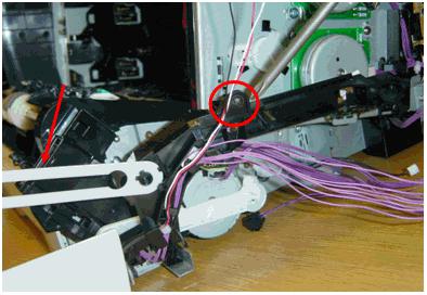
7.Remove the bottom cable harness. There is one screw at the top to remove. Hint: when you reinstall the guide, make sure that the rear locking tab is seated in the sheet-metal chassis. (See page 120 - 121 in the service manual). It may be necessary to disconnect the white door latch from the front door. (Notice the red arrow call-out).
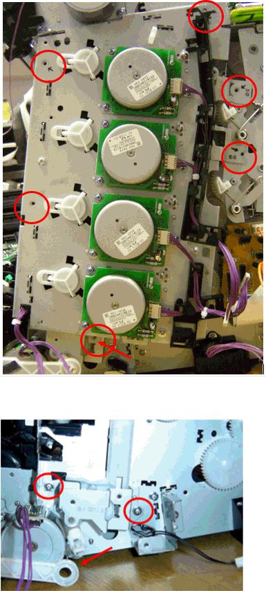
8.Remove the main drive assembly (MDA). There are six screws attaching the MDA to the chassis. Carefully note the locations of the screws to be removed.
CAUTION: Removing the incorrect screws could lead to opening up the MDA, requiring a unit replacement!
NOTE: Two gears may fall off, there are instructions in step 16 on how to align them during the re-installation process.
Remove the metal case by removing two screws. Remove the White Link Arm (see arrow in figure below)
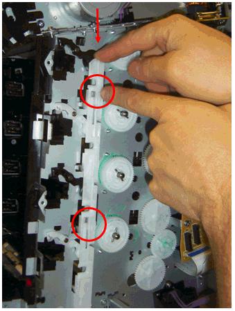
9.Remove the white slide lever by pushing down from the top to release it from the two tabs. Carefully remove the lever by pulling out, be aware that four springs are attached to this lever and the individual cartridge locks.
10.Once the sliding lever is removed, the cartridge locks can be accessed. The new grounding springs are not on the new cartridge locks and will need to be attached. Look at the current springs on the machine for guidance, and at the instructions below. Make sure to feed the hooked end through the hole at the end of the lock to begin with (See figure below.).
NOTE: The service kit has four new locks and four new springs in it, replace all the locks and springs, even if they are not currently broken. The new kit has white colored countermeasured locks. The picture below shows an old black non-countermeasured lock.
 Loading...