


2930M
Table of contents
 Loading...
Aruba 2930F Switch Series Installation and Getting Started Guide
Part Number: 5200-1194a
Published: 2018 January
Edition: 2

©
Copyright 2018, Hewlett Packard Enterprise Development LP
Notices
The information contained herein is subject to change without notice. The only warranties for Hewlett Packard
Enterprise products and services are set forth in the express warranty statements accompanying such products
and services. Nothing herein should be construed as constituting an additional warranty. Hewlett Packard
Enterprise shall not be liable for technical or editorial errors or omissions contained herein.
Confidential computer software. Valid license from Hewlett Packard Enterprise required for possession, use, or
copying. Consistent with FAR 12.211 and 12.212, Commercial Computer Software, Computer Software
Documentation, and Technical Data for Commercial Items are licensed to the U.S. Government under vendor's
standard commercial license.
Links to third-party websites take you outside the Hewlett Packard Enterprise website. Hewlett Packard Enterprise
has no control over and is not responsible for information outside the Hewlett Packard Enterprise website.
Acknowledgments
Intel®, Itanium®, Pentium®, Intel Inside®, and the Intel Inside logo are trademarks of Intel Corporation in the United
States and other countries.
Microsoft® and Windows® are either registered trademarks or trademarks of Microsoft Corporation in the United
States and/or other countries.
Adobe® and Acrobat® are trademarks of Adobe Systems Incorporated.
Java® and Oracle® are registered trademarks of Oracle and/or its affiliates.
UNIX® is a registered trademark of The Open Group.
Applicable products
Aruba 2930F 24G 4SFP+ Switch JL253A
Aruba 2930F 48G 4SFP+ Switch JL254A
Aruba 2930F 24G 4SFP Switch JL259A
Aruba 2930F 48G 4SFP Switch JL260A
Aruba 2930F 8G PoE+ 2SFP+ Switch JL258A
Aruba 2930F 24G PoE+ 4SFP+ Switch JL255A
Aruba 2930F 48G PoE+ 4SFP+ Switch JL256A
Aruba 2930F 24G PoE+ 4SFP Switch JL261A
Aruba 2930F 48G PoE+ 4SFP Switch JL262A
Aruba 2930F 24G PoE+ 4SFP+ TAA Switch JL263A
Aruba 2930F 48G PoE+ 4SFP+ TAA Switch JL264A
Aruba 2930F 48G PoE+ 4SFP 740W Switch JL557A
Aruba 2930F 48G PoE+ 4SFP+ 740W Switch JL558A
Aruba 2930F 48G PoE+ 4SFP+ 740W TAA Switch JL559A

Contents
Chapter 1 Introducing the 2930F switches.................................................... 5
Front of the 2930F switches.......................................................................................................................6
Network ports.................................................................................................................................. 8
Management ports........................................................................................................................ 10
Console Ports.....................................................................................................................10
Switch and port LEDs on front of the switches..............................................................................10
LED mode select button and indicator LEDs......................................................................14
Reset and Clear buttons............................................................................................................... 14
Back of the switches................................................................................................................................ 16
Power connector........................................................................................................................... 16
Switch features........................................................................................................................................ 16
Chapter 2 Installing the switch..................................................................... 19
Included parts.......................................................................................................................................... 19
Installation procedures.............................................................................................................................22
Installation precautions................................................................................................................. 23
Prepare the installation site......................................................................................................................24
Verify the switch passes self test............................................................................................................. 24
LED behavior:............................................................................................................................... 26
Mount the switch...................................................................................................................................... 27
Mounting a 24–port or 48–port Aruba 2930F switch..................................................................... 27
Mounting the Aruba 2930F 8G PoE+ 2SFP+ Switch (JL258A).....................................................29
Install or remove SFP/SFP+ transceivers................................................................................................34
Installing the transceivers..............................................................................................................35
Removing the transceiver:............................................................................................................ 35
Connect the switch to a power source..................................................................................................... 36
(Optional) Connect a management console............................................................................................ 37
Terminal configuration...................................................................................................................38
Direct console access................................................................................................................... 39
Console cable pinouts...................................................................................................................40
Connect the network cables.....................................................................................................................40
Using the RJ-45 connectors..........................................................................................................40
Connecting cables to transceivers................................................................................................ 41
Sample network topologies........................................................................................................... 42
Chapter 3 Getting started with switch configuration..................................44
Recommended minimal configuration......................................................................................................44
Using the console setup screen.................................................................................................... 44
Where to go from here.................................................................................................................. 46
Using the IP address for remote switch management............................................................................. 47
Starting a Telnet session...............................................................................................................47
Starting a web browser session.................................................................................................... 47
Chapter 4 Troubleshooting............................................................................49
Basic troubleshooting tips........................................................................................................................ 49
Diagnosing with the LEDs........................................................................................................................50
LED patterns for general switch troubleshooting.......................................................................... 50
Contents 3

LED patterns for PoE troubleshooting...........................................................................................55
Proactive networking................................................................................................................................55
Hardware diagnostic tests........................................................................................................................56
Testing the switch by resetting it................................................................................................... 56
Checking the switch LEDs............................................................................................................ 56
Checking console messages........................................................................................................ 56
Testing twisted-pair cabling...........................................................................................................57
Testing switch-to-device network communications....................................................................... 57
Testing end-to-end network communications................................................................................57
Restoring the factory default configuration.............................................................................................. 57
Downloading new switch software........................................................................................................... 58
Chapter 5 Specifications............................................................................... 59
Switch specifications................................................................................................................................59
Technology standards and safety compliance......................................................................................... 63
Chapter 6 Cabling and technology information.......................................... 64
Cabling specifications.............................................................................................................................. 64
Technology distance specifications..........................................................................................................65
Mode conditioning patch cord.................................................................................................................. 66
Installing the patch cord................................................................................................................ 66
Twisted-pair cable/connector pinouts.......................................................................................................67
Auto-MDIX feature........................................................................................................................ 67
Other wiring rules.......................................................................................................................... 68
Straight-through twisted-pair cable for 10 Mbps or 100 Mbps network connections.....................68
Cable diagram.................................................................................................................... 68
Pin assignments................................................................................................................. 69
Crossover twisted-pair cable for 10 Mbps or 100 Mbps network connection................................69
Cable diagram.................................................................................................................... 69
Pin assignments................................................................................................................. 70
Straight-through twisted-pair cable for 1000 Mbps network connections......................................70
Cable diagram.................................................................................................................... 70
Pin assignments................................................................................................................. 71
Chapter 7 Websites........................................................................................ 72
Chapter 8 Support and other resources...................................................... 73
Accessing Hewlett Packard Enterprise Support...................................................................................... 73
Accessing updates...................................................................................................................................73
Customer self repair.................................................................................................................................74
Remote support....................................................................................................................................... 74
Warranty information................................................................................................................................74
Regulatory information.............................................................................................................................75
Documentation feedback......................................................................................................................... 75
Chapter 9 Warranty and regulatory information..........................................76
4 Aruba 2930F Switch Series Installation and Getting Started Guide

Chapter 1
Introducing the 2930F switches
The Aruba 2930F are multiport switches that can be used to build high-performance switched networks. These
switches are store-and-forward devices offering low latency for high-speed networking. The 2930F switches also
support Power over Ethernet (PoE/PoE+) technologies and full network management capabilities.
These switches are described in this manual:
Non-PoE switches PoE+ switches
Aruba 2930F 24G 4SFP+ Switch (JL253A) Aruba 2930F 24G PoE+ 4SFP+ Switch (JL255A)
Aruba 2930F 48G 4SFP+ Switch (JL254A) Aruba 2930F 48G PoE+ 4SFP+ Switch (JL256A)
Aruba 2930F 24G 4SFP Switch (JL259A) Aruba 2930F 24G PoE+ 4SFP Switch (JL261A)
Aruba 2930F 48G 4SFP Switch (JL260A) Aruba 2930F 48G PoE+ 4SFP Switch (JL262A)
Aruba 2930F 8G PoE+ 2SFP+ Switch (JL258A)
Aruba 2930F 24G PoE+ 4SFP+ TAA Switch (JL263A)
Aruba 2930F 48G PoE+ 4SFP+ TAA Switch (JL264A)
Aruba 2930F 48G PoE+ 4SFP 740W Switch (JL557A)
Aruba 2930F 48G PoE+ 4SFP+ 740W Switch (JL558A)
Aruba 2930F 48G PoE+ 4SFP+ 740W TAA Switch
(JL559A)
This chapter describes these switches with the following information:
• Front of the switches:
◦ Network ports
◦ Management ports
◦ LEDs
◦ Buttons
• Back of the switches:
◦ Power connectors
• Switch features
The drawings in this publication are for illustration only and may not match your particular 2930F
switch model.
Chapter 1 Introducing the 2930F switches 5
Front of the 2930F switches
1
2
3
4
5
6
7
8
9
10
11
12
13
14
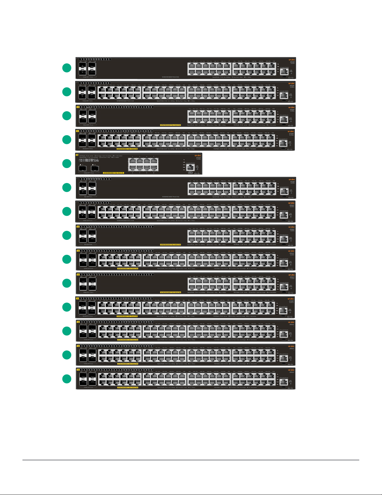
Figure 1: Front of all the 2930F switches
6 Aruba 2930F Switch Series Installation and Getting Started Guide
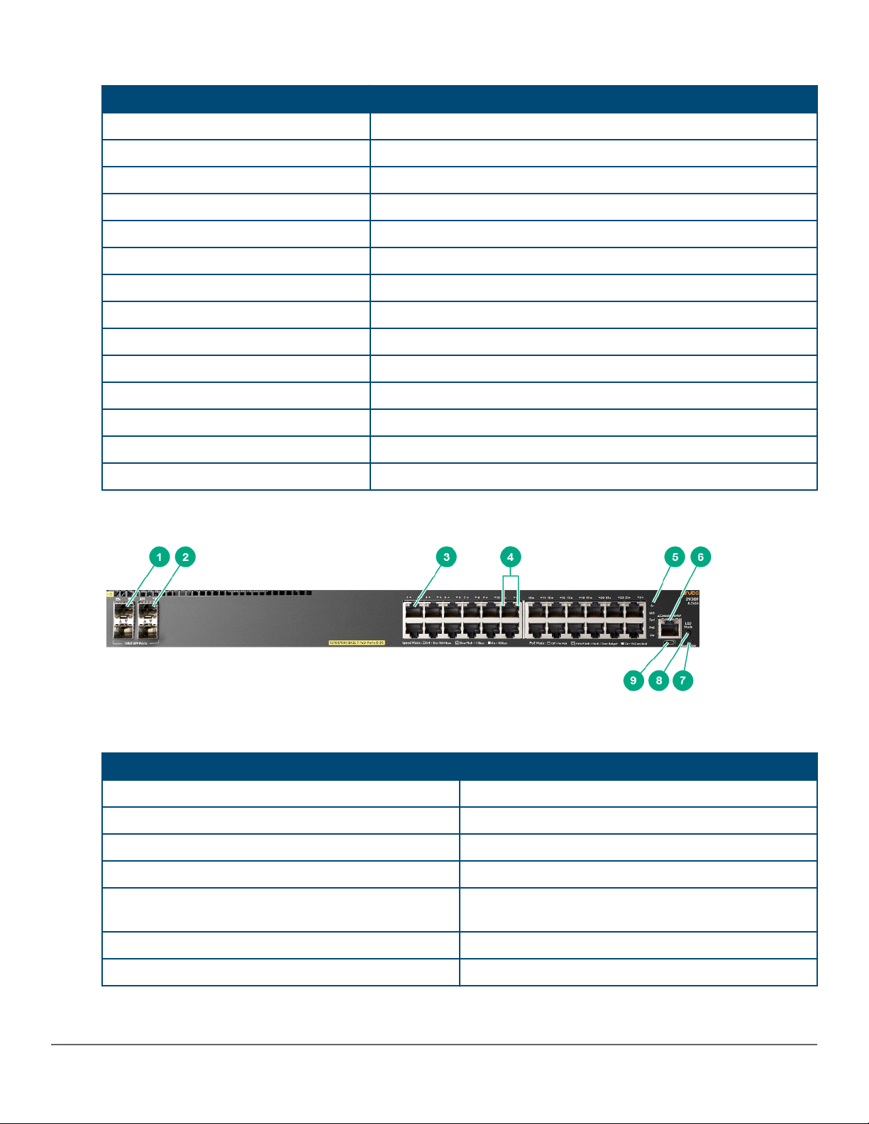
Table 1: Front of all the 2930F switches: Label and description
Label Description
1 Aruba 2930F 24G 4SFP+ Switch (JL253A)
2 Aruba 2930F 48G 4SFP+ Switch (JL254A)
3 Aruba 2930F 24G PoE+ 4SFP+ Switch (JL255A)
4 Aruba 2930F 48G PoE+ 4SFP+ Switch (JL256A)
5 Aruba 2930F 8G PoE+ 2SFP+ Switch (JL258A)
6 Aruba 2930F 24G 4SFP Switch (JL259A)
7 Aruba 2930F 48G 4SFP Switch (JL260A)
8 Aruba 2930F 24G PoE+ 4SFP Switch (JL261A)
9 Aruba 2930F 48G PoE+ 4SFP Switch (JL262A)
10 Aruba 2930F 24G PoE+ 4SFP+ TAA Switch (JL263A)
11 Aruba 2930F 48G PoE+ 4SFP+ TAA Switch (JL264A)
12 Aruba 2930F 48G PoE+ 4SFP 740W Switch (JL557A)
13 Aruba 2930F 48G PoE+ 4SFP+ 740W Switch (JL558A)
14 Aruba 2930F 48G PoE+ 4SFP+ 740W TAA Switch (JL559A)
Figure 2: Example of the Front of the 2930F switches labels and descriptions
Table 2: Front of the 2930F switches labels and descriptions
Label Description
1 SFP/SFP+ ports
2 SFP/SFP+ port LEDs
3 10/100/1000 Base-T RJ-45 ports
4 Switch port LEDs
5 Global Status, Unit Identification, Speed, PoE*, Usr
LEDs
6 RJ Serial Console
7 Reset, Clear buttons
Table Continued
Chapter 1 Introducing the 2930F switches 7
Label Description
8 LED Mode button
9 Micro USB Console
* PoE Mode LED is present only on switch models that support PoE.
Network ports
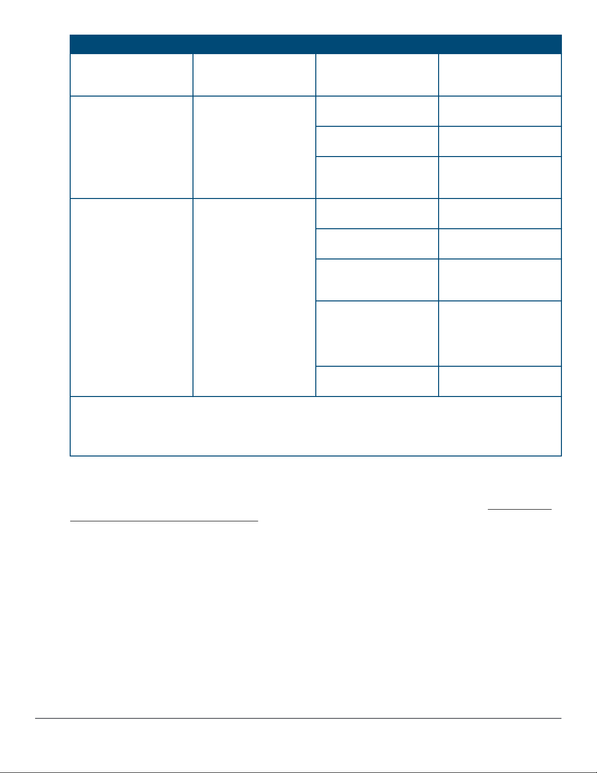
Table 3: Network ports
Product
Model name 10/100/1000
number
JL253A Aruba 2930F
24G 4SFP+
Switch
JL254A Aruba 2930F
48G 4SFP+
Switch
JL255A Aruba 2930F
24G PoE+ 4SFP
+ Switch
JL256A Aruba 2930F
48G PoE+ 4SFP
+ Switch
JL258A Aruba 2930F 8G
PoE+ 2SFP+
Switch
JL259A Aruba 2930F
24G 4SFP
Switch
non-PoE RJ-45
1
ports
24 - - 4
48 - - 4
- 24 - 4
- 48 - 4
- 8 - 2
24 - 4 -
10/100/1000
PoE/PoE+
RJ-45 ports
1
SFP ports
2
SFP+ ports
3
JL260A Aruba 2930F
48 - 4 48G 4SFP
Switch
JL261A Aruba 2930F
- 24 4 24G PoE+ 4SFP
Switch
JL262A Aruba 2930F
- 48 4 48G PoE+ 4SFP
Switch
JL263A Aruba 2930F
- 24 - 4
24G PoE+ 4SFP
+ TAA Switch
JL264A Aruba 2930F
- 48 - 4
48G PoE+ 4SFP
+ TAA Switch
Table Continued
8 Aruba 2930F Switch Series Installation and Getting Started Guide
Product
number
Model name 10/100/1000
non-PoE RJ-45
1
ports
10/100/1000
PoE/PoE+
RJ-45 ports
1
SFP ports
2
SFP+ ports
3
JL557A Aruba 2930F
- 48 4 48G PoE+ 4SFP
740W Switch
JL558A Aruba 2930F
- 48 - 4
48G PoE+ 4SFP
+ 740W Switch
JL559A Aruba 2930F
- 48 - 4
48G PoE+ 4SFP
+ 740W TAA
Switch
Notes:
1
All RJ-45 ports support “Auto-MDIX”, which means you can use either straight-through or crossover twisted-
pair cables to connect network devices to the switch.
2
SFP ports support 100Mb (100-FX) and 1G SFP transceivers.
3
SFP+ ports support 100Mb (100-FX), 1G SFP, and 10G SFP+ transceivers.
1000-T Copper (twisted-pair) RJ-45
1000-SX Fiber (multimode) LC
1000-LX Fiber (multimode or single mode) LC
1000-LH Fiber (single mode) LC
1000-BX Fiber (single mode) LC
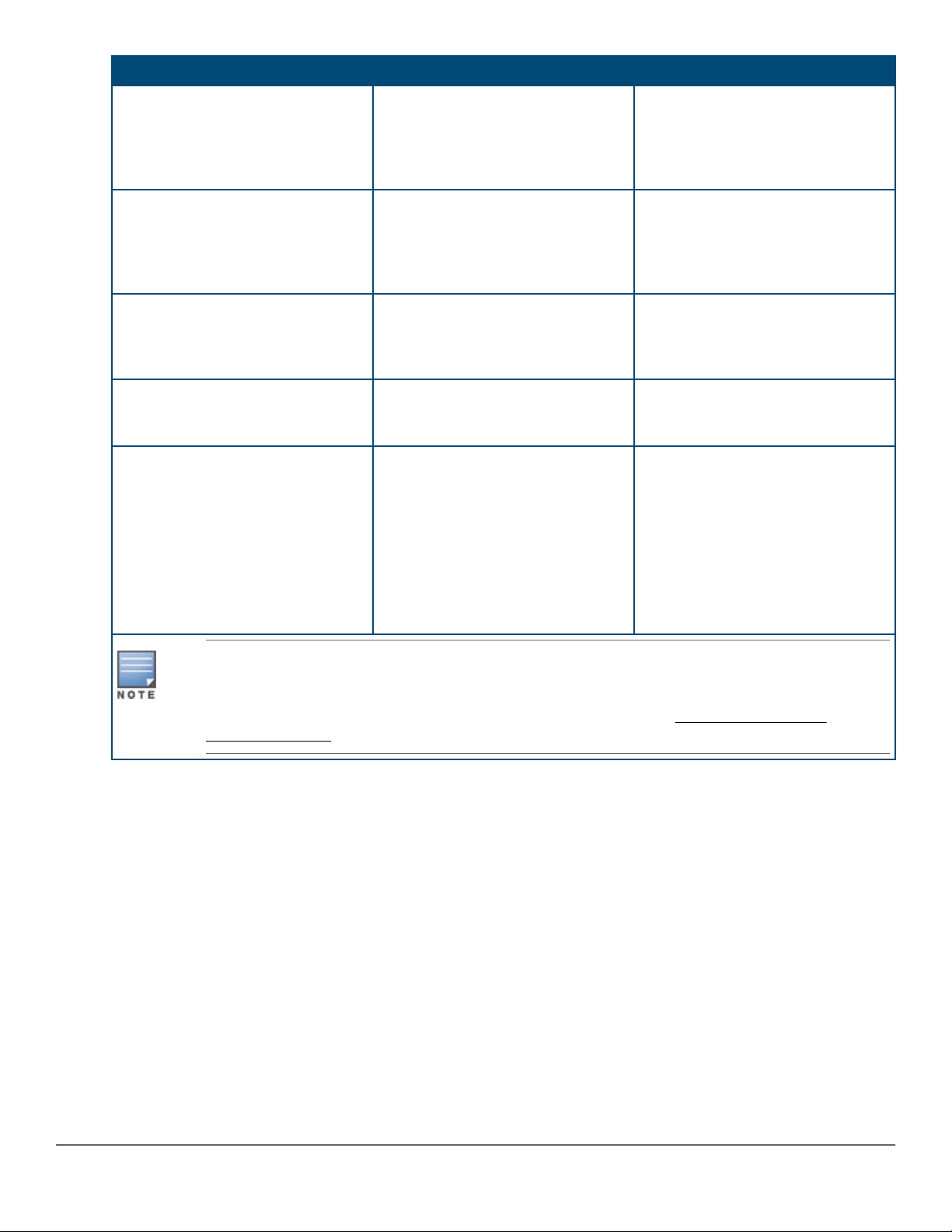
These products also support optional network connectivity:
Table 4: Optional network connectivity, speeds, and technologies
Transceiver Form-Factor and Connector
Speed Technology Cabling SFP ("mini-GBIC")
Connector
100 Mbps 100-FX Fiber (multimode) LC -
1000 Mbps 1000-T Copper (twisted-
RJ-45 -
pair)
1000-SX Fiber (multimode) LC -
1000-LX Fiber (multimode or
LC -
single mode)
1000-LH Fiber (single mode) LC -
1000-BX Fiber (single mode) LC -
10 Gbps 10-Gig Direct
Copper (twinaxial) - Not Applicable
Attach
SFP+ Connector
1
Table Continued
Chapter 1 Introducing the 2930F switches 9
10-Gig SR Fiber (multimode) - LC
10-Gig LR Fiber (single mode) - LC
10-Gig ER Fiber (single mode) - LC
1
For supported transceivers, visit http://www.hpe.com/networking/support.
• In the first text box, type J4858 (for 100-Mb and Gigabit information), J8436 (for 10-Gigabit information), or
JH231 (for 40–Gigabit information).
• Select any of the products that display in the drop-down list.
• Select Support Center > Manuals > View All to find the Transceiver Support Matrix.
For technical details of cabling and technologies, see Cabling and technology information.
Management ports
Console Ports
There are two serial console port options on the switch, an RJ-45 or Micro USB. These ports are used to connect
a console to the switch either by using the RJ-45 serial cable supplied with the switch, or a standard Micro USB
cable (not supplied). The Micro USB connector has precedence for input. If both cables are plugged in, the
console output is echoed to both the RJ-45 and the Micro-USB ports, but the input is only accepted from the
Micro-USB port.
For more information on the console connection, see
can be a PC or workstation running a VT-100 terminal emulator, or a VT-100 terminal.
(Optional) Connect a management console. The console
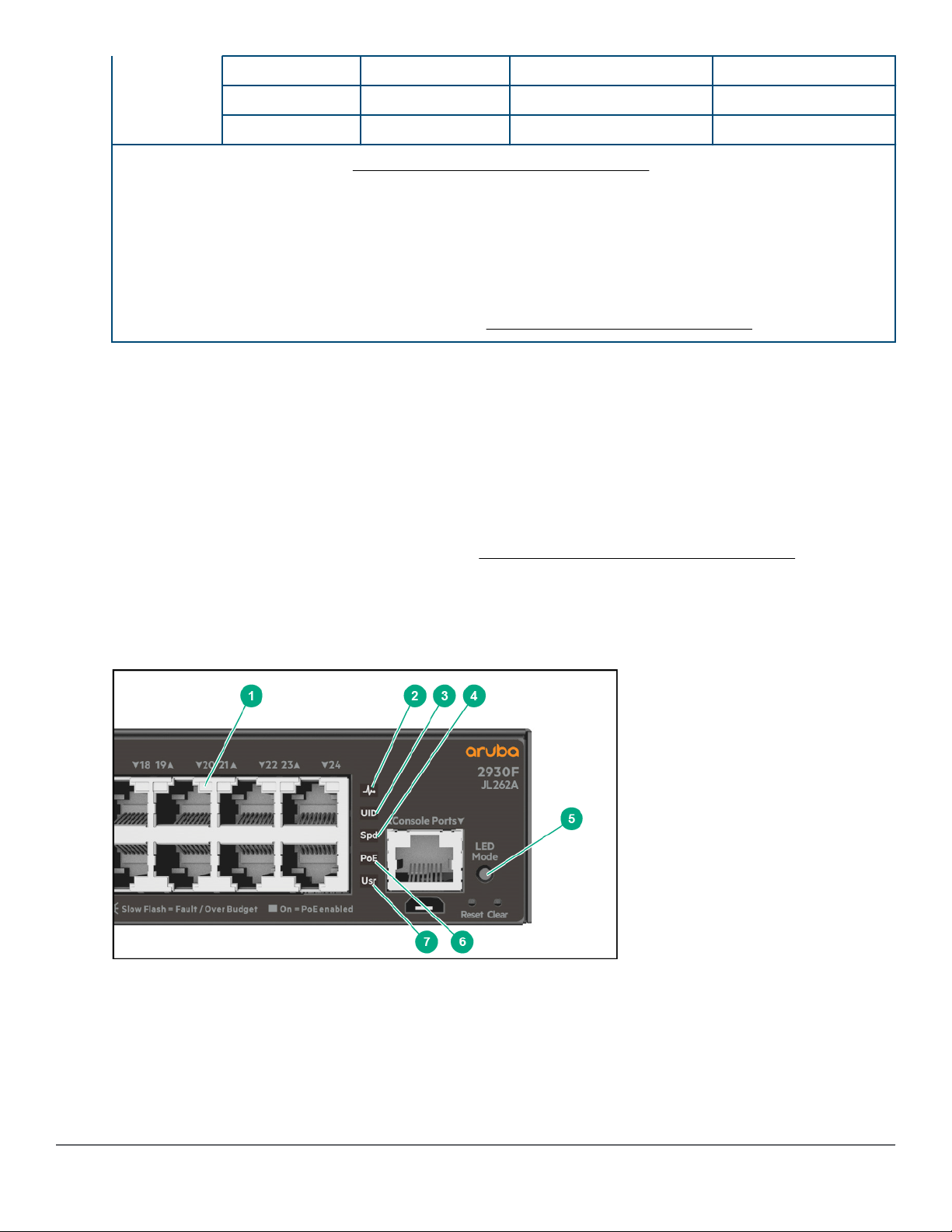
Switch and port LEDs on front of the switches
Figure 3: Switch and port LEDs
10 Aruba 2930F Switch Series Installation and Getting Started Guide
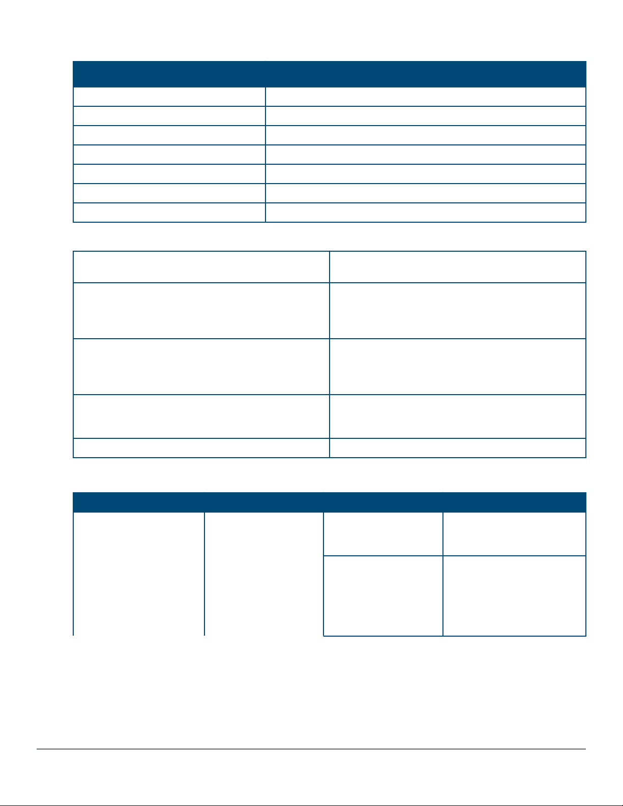
Table 5: Switch and port LEDs: Labels and description
Label
Description
1 Switch port LEDs
2 Global status LED
3 Unit identification LED
4 Speed LED
5 LED Mode button
6 PoE LED
1
7 Usr LED
1
PoE Mode LED is present only on switch models that support PoE.
On green The switch has passed self-test and is powered up
normally.
Slow flash green* The switch self-test and initialization are in progress
after the switch has been power cycled or reset. The
switch is not operational until this LED stops blinking
green.
Slow flash orange* A fault or self-test failure has occurred n the switch,
one of the switch ports, or a
fan.TheStatusLEDforthecomponentwiththefaultwillflash
simultaneously.
On orange If this LED is on orange for a prolonged time, the
switch has encountered a fatal hardware failure, or has
failed its self-test.
Off The unit is not receiving power.
Table 6: Front of switch status and mode LED behavior
Switch LEDs Function State Meaning
Global status Internal power status of
the switch. Self-test
status Switch/port fault
status.
On green The switch has passed self-
test and is powered up
normally.
Slow flash green* The switch self-test and
initialization are in progress
after the switch has been
power cycled or reset. The
switch is not operational until
this LED stops blinking green.
Table Continued
Chapter 1 Introducing the 2930F switches 11
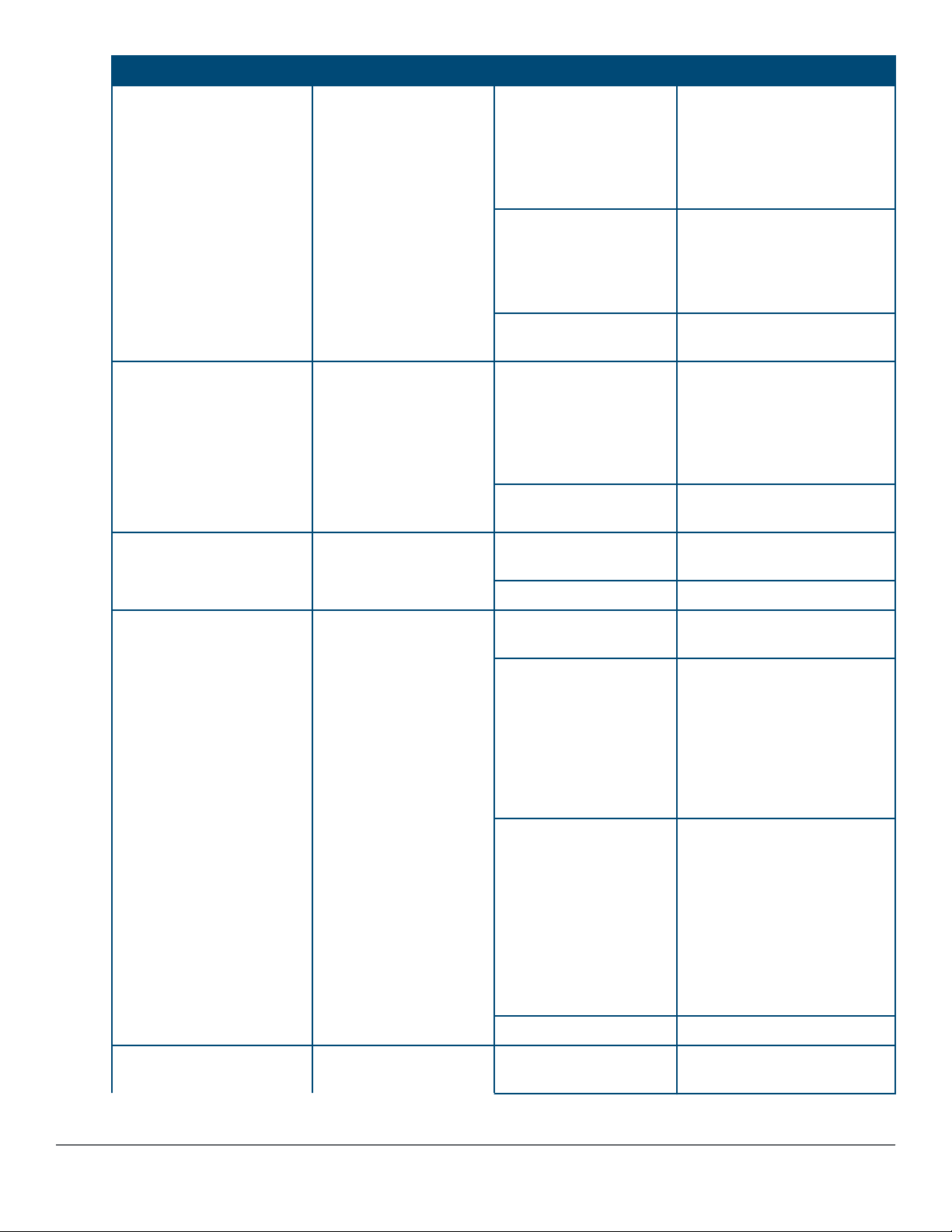
Switch LEDs Function State Meaning
Slow flash orange* A fault or self-test failure has
occurred n the switch, one of
the switch ports, or a
fan.TheStatusLEDforthecomp
onentwiththefaultwillflashsimu
ltaneously.
On orange If this LED is on orange for a
prolonged time, the switch
has encountered a fatal
hardware failure, or has failed
its self-test.
Off The unit is not receiving
power.
UID (Unit identification) The Unit Identification
LED is used to help you
to identify a particular
unit in a rack or
collection of products.
Speed mode selected Indicates when the Port
LEDs are showing port
speed information.
Power over Ethernet (PoE)
mode selected**
Indicates when the Port
LEDs are showing PoE
status information.
On or slow flash* The "chassislocate"
command allows you to blink
or turn on the LED for a
specified number of minutes
(1-1440). The default is 30
minutes.
Off LED will turn off after the
timeout period has expired.
On Speed mode is selected. Port
LEDs indicate port speed.
Off Speed mode not selected.
On green PoE mode is selected. Port
LEDs show PoE information.
On orange PoE mode is selected and a
port also has a PoE error. The
Global Status LED and the
LED corresponding to the port
with the error will be flashing
orange. The rest of the port
LEDs will display normal PoE
status.
Slow flash orange* PoE mode has NOT been
selected and a port has a
PoE error. LED will be
flashing orange
simultaneously with the
Global Status LED and the
LED corresponding to the port
with the error. The rest of the
port LEDs will display normal
PoE status.
Off PoE mode is not selected.
User mode selected This mode is reserved
for future use.
12 Aruba 2930F Switch Series Installation and Getting Started Guide
On green User mode is selected.
Table Continued
Switch LEDs Function State Meaning
Off User mode not selected.
* The slow blink behavior is an on/off cycle once every 1.6 seconds, approximately.
** Applies only to switches that support PoE/PoE+.
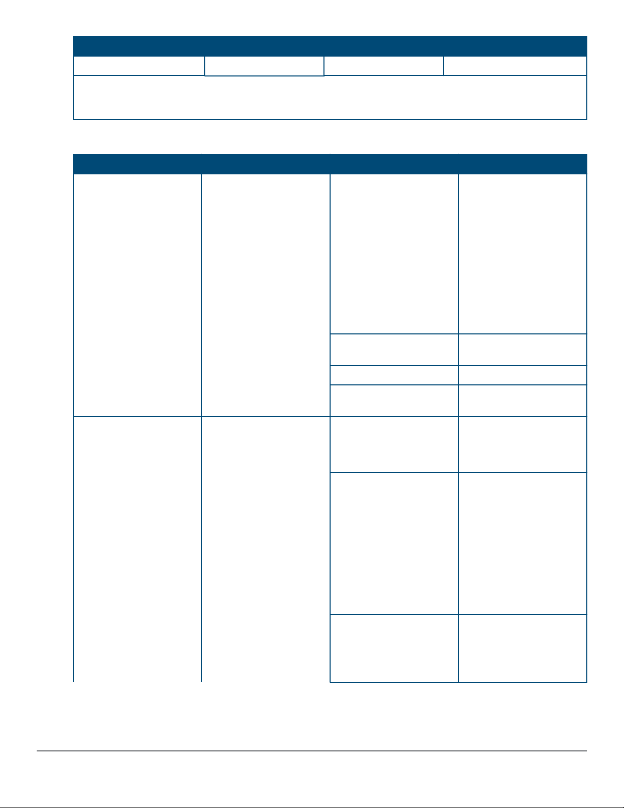
Table 7: Port LEDs and mode behavior
Switch LEDs Function State/Mode Meaning
Port LEDs
Activity/Link mode
selected
To display the information
for the port as selected by
the LED Mode select
button.
When transceivers and
SFPs are installed, this
LED is also used to
indicate that the
installation has occurred
by going on for two
seconds then off.
Port LEDs are displaying
link status and network
activity information
simultaneously.
Activity/Link mode is the
default mode and is in
effect unless another LED
mode has been selected.
Activity/Link
Speed Shows port speed
PoE*** Shows PoE information.
User Shows user-selectable
Half-bright green The port is enabled and
Activity flicker green
Shows port Activity and
Link status.
This is the DEFAULT.
There is no dedicated
mode LED indicating this
mode.
The Mode LED function
should return to this
selection 10 minutes after
the last press of the LED
Mode button.
configuration.
behavior.
receiving a link indication
from the connected
device.
The percentage of time
that the LED is full-bright
is roughly proportional to
the percentage of fullbandwidth utilization of the
port.
Half-bright green port link
indication remains on as
activity flickers from halfbright to full-bright.
Slow flash orange* The corresponding port
has failed its self-test.
Flashes simultaneously
with the Global Status
LED flashing orange.
Table Continued
Chapter 1 Introducing the 2930F switches 13
Switch LEDs Function State/Mode Meaning
Off The port is disabled, not
connected, or not
receiving a link.
Speed mode selected Port LEDs are displaying
the connection speed at
which each port is
operating.
PoE mode selected*** Port LEDs are displaying
PoE information.
On green The port is operating at 10
Gbps.
Slow flash green* The port is operating at 1
Gbps.
Off The port is not Linked, or
is operating at 10 or 100
Mbps.
On green The port is providing PoE
power.
On orange PoE is disabled on the
port.
Fast flash orange** The port is denied power
or is detecting an external
PD fault.
Slow flash orange* The port has an internal
hardware failure. Flashes
simultaneously with the
Global Status LED
flashing orange.
Off The port is not providing
PoE power.
* The slow blink behavior is an on/off cycle once every 1.6 seconds, approximately.
** The fast blink behavior is an on/off cycle once every 0.8 seconds, approximately.
*** Applies only to switches that support PoE/PoE+.
LED mode select button and indicator LEDs
The state of the Mode LEDs is controlled by the LED Mode select button. The current view mode is indicated by
the Mode LEDs next to the button. Press the button to step from one view mode to the next. See Table 6: Front
of switch status and mode LED behavior on page 11.
Reset and Clear buttons
The Reset and Clear buttons are recessed from the front panel (to protect them from being pushed accidentally)
and are accessible through small holes on the top of the front panel. Use pointed objects, such as unbent paper
clips, to push them.
The Reset and Clear buttons are used singly or in combination, as follows:
14 Aruba 2930F Switch Series Installation and Getting Started Guide
To accomplish this: Do this: This will happen:
Soft reset Press and release the Reset button The switch operating system is
cleared gracefully (such as data
transfer completion, temporary error
conditions are cleared), then
reboots and runs self tests.
Hard reset Press and hold the Reset button for
more than 5 seconds (until all LEDs
turn on), then release.
Delete console and management
access passwords
Turn off UID LED Press Clear button and release
Restore the factory default
configuration
Press Clear button for more than 5
seconds, but within 15 seconds (in
between 5 - 15 seconds)
within 5 seconds (in betwween 0.5 5 seconds)
1. Press Clear and Reset
simultaneously.
2. While continuing to press Clear,
release Reset.
3. When the Global Status LED
begins to fast flash orange (after
approximately 5 seconds), release
Clear.
The switch reboots, similar to a
power cycle. A hard reset is used,
for example, when the switch CPU
is in an unknown state or not
responding.
Clears all passwords. Will flash
Global Status Green LED, after 5
seconds has expired to indicate
passwords have cleared.
Clears the UID LED.
The switch removes all
configuration changes, restores the
factory default configuration, and
runs self test.
These buttons are provided for your convenience. If you are concerned with switch security, make
sure that the switch is installed in a secure location, such as a locked wiring closet. You can also
disable these buttons by using the front-panel-security command. For a description of that
command, see the 2930M Management and Configuration Guide at http://www.hpe.com/
support/manuals.
Chapter 1 Introducing the 2930F switches 15
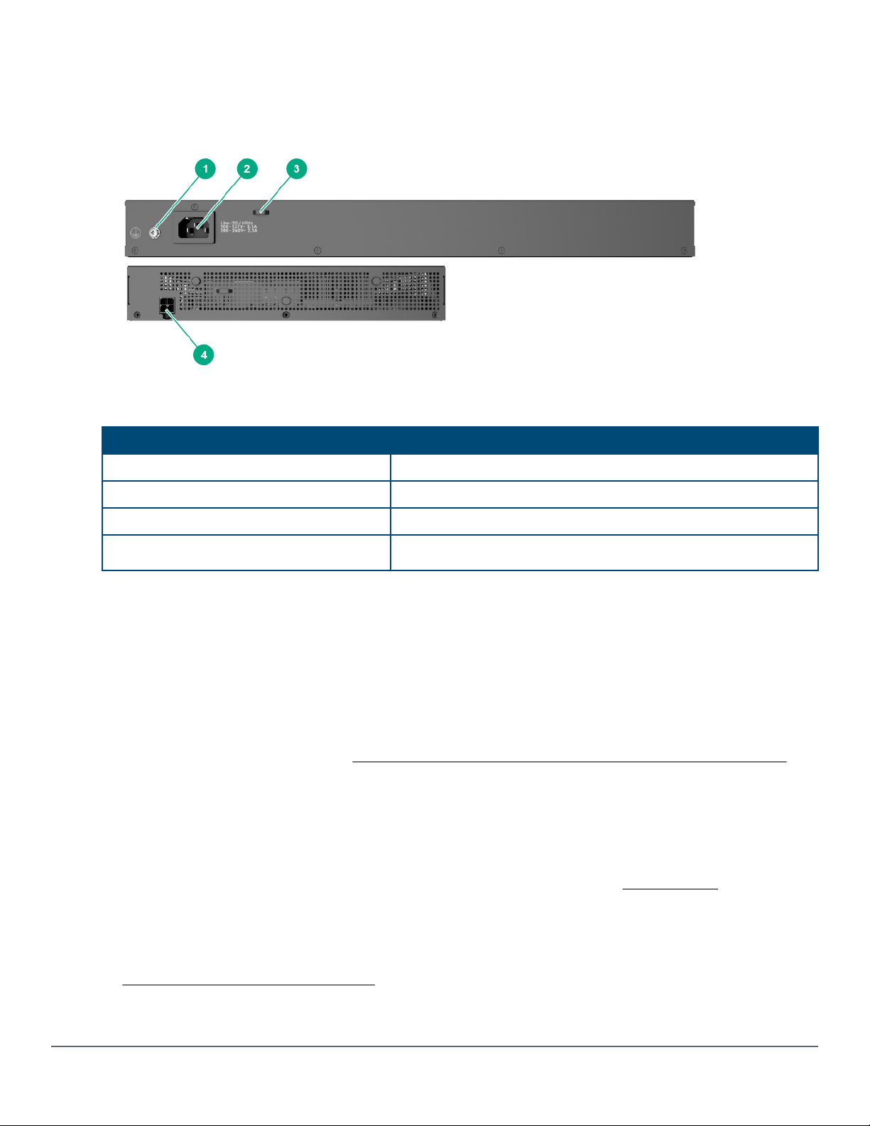
Back of the switches
TThe back of all the 24-port and 48-port switches are the same.
Figure 4: Back of the 2930F switches
Table 8:
Back of the 2930F switches labels and descriptions
Label Description
1 Ground point
2 AC power connector
3 Cable tie eyelet
4
DC power jack (JL258A)
Power connector
The 2930F 24-port and 48-port switches do not have a power switch; they are powered on when connected to an
active AC power source. The switches automatically adjust to any voltage between 100-127 and 200-240 volts
and either 50 or 60 Hz. There are no voltage range settings required.
The Aruba 2930F 8G PoE+ 2SFP+ Switch (JL258A) does not have a power switch, it is powered on when the
external AC/DC power adapter is connected to the switch and to a power source. The external AC/DC power
adapter supplies 54 volts DC to the switch and automatically adjusts to any AC voltage between 100-240 volts
and either 50 or 60 Hz. No voltage range settings are required. Be sure to release the latch on the DC plug before
removing the adapter power cord. (See Figure 19: Aruba 2930F 8G PoE+ 2SFP+ Switch power plug latch on
page 37.)
Switch features
The features of the 2930F switches include:
• Combinations of fixed 10/100/1000-T and SFP/SFP+ ports, as described under Network ports on page 8.
• Power over Ethernet (PoE+) operation (JL255A, JL256A, JL258A, JL261A, JL262A, JL263A, JL264A, JL557A,
JL558A, JL559A)—The PoE+ switches are IEEE 802.3at standard compliant and provide up to 30W per port
to power IP phones, wireless access points, indoor web cameras, and more. For more information, see the
latest version of the HPE Power over Ethernet (PoE/PoE+) Planning and Implementation Guide, available from
http://www.hpe.com/support/manuals.
16 Aruba 2930F Switch Series Installation and Getting Started Guide

The switches support 802.3af and 802.3at standard devices and some pre-standard PoE devices. For a list of
these devices, see the FAQs (Frequently Asked Questions) for your switch model. PoE is enabled by default.
(For more information, see the 2930F Management and Configuration Guide for your switch at http://
www.hpe.com/support/manuals.
• Plug-and-play networking. All ports are enabled by default, just connect the network cables to active network
devices and your switched network is operational.
• Auto MDI/MDI-X on all twisted-pair ports (10/100/1000Base-T), meaning that all connections can be made
using straight-through twisted-pair cables. Cross-over cables are not required, although they will also work.
The pin operation of each port is automatically adjusted for the attached device: if the switch detects that
another switch or hub is connected to the port, it configures the port as MDI; if the switch detects that an endnode device is connected to the port, it configures the port as MDI-X. See Cabling and technology
information for recommended or required cabling.
• Automatic learning of the network addresses in each switch’s 64000-address forwarding table (with
configurable address aging value).
• Automatically negotiated full-duplex operation for the 10/100/1000 RJ-45 ports when connected to other autonegotiating devices. The SFP/SFP+ ports always operate at full duplex.
• Easy management of the switch through several available interfaces:
◦ Console interface: A full-featured, easy-to-use, VT-100 terminal interface for out-of-band or in-band switch
management.
◦ Web browser interface: An easy-to-use built-in graphical interface that can be accessed from common
web browsers.
◦ Aruba AirWave: A powerful and easy-to-use network operations system that manages wired and wireless
infrastructures.
◦ IMC: An SNMP-based, graphical network management tool that you can use to manage your entire
network. Free trials of IMC can be downloaded at http://www.hpe.com/networking/imc.
• Support for the Spanning Tree Protocol to eliminate network loops.
• Support for up to 4096 IEEE 802.1Q-compliant VLANs so you can divide the attached end nodes into logical
groupings that fit your business needs.
• Support for many advanced features to enhance network performance: For a description, see the 2930F
Management and Configuration Guide at http://www.hpe.com/support/manuals.
• To download product updates, go to either of the following:
◦ Hewlett Packard Enterprise Support Center Get connected with updates page: http://www.hpe.com/
support/e-updates
◦ HPE Networking Software: http://www.hpe.com/networking/software
• To view and update your entitlements and to link your contracts and warranties with your profile, go to the
Hewlett Packard Enterprise Support Center More Information on Access to Support Materials page: http://
www.hpe.com/support/AccessToSupportMaterials.
• Low-power operation:
Chapter 1 Introducing the 2930F switches 17

◦ Ports on a switch or stack member may be set to operate at reduced power.
◦ Port status LEDs may be turned off.
◦ RJ-45 ports will operate at reduced power if the port is not connected (link partner is not detected).
18 Aruba 2930F Switch Series Installation and Getting Started Guide

Chapter 2
Installing the switch
This chapter shows how to install the switch. The 2930F switches come with an accessory kit that includes the
brackets for mounting the switch in a standard 19-inch telco rack, in an equipment cabinet, and with rubber feet
that can be attached so the switch can be securely located on a horizontal surface. The brackets are designed to
allow mounting the switch in a variety of locations and orientations. The Aruba 2930F 8G PoE+ 2SFP+ Switch
(JL258A) also includes brackets that enable it to be mounted on a wall or under a table. For other mounting
options contact your local Hewlett Packard Enterprise authorized network reseller or Hewlett Packard Enterprise
representative.
If an Aruba 2930F 24G or 48G switch is to be shipped in a rack, it can be mounted and shipped in a
Hewlett Packard Enterprise 10K rack using the HPE X410 Universal Rack Mounting Kit (J9583A).
Additionally, it can also be mounted in any four post rack using the HPE X410 Universal Rack
Mounting Kit (J9583A).
The Aruba 2930F 8G PoE+ 2SFP+ Switch is not designed for shipping in a rack.
Included parts
The 2930F switches have the following components shipped with them:
• Aruba Switch Quick Setup Guide and Safety/Regulatory Information
• Switch Safety and Regulatory sheet
• Warranty notice
• General Safety and Regulatory booklet
• Accessory kits
Chapter 2 Installing the switch 19
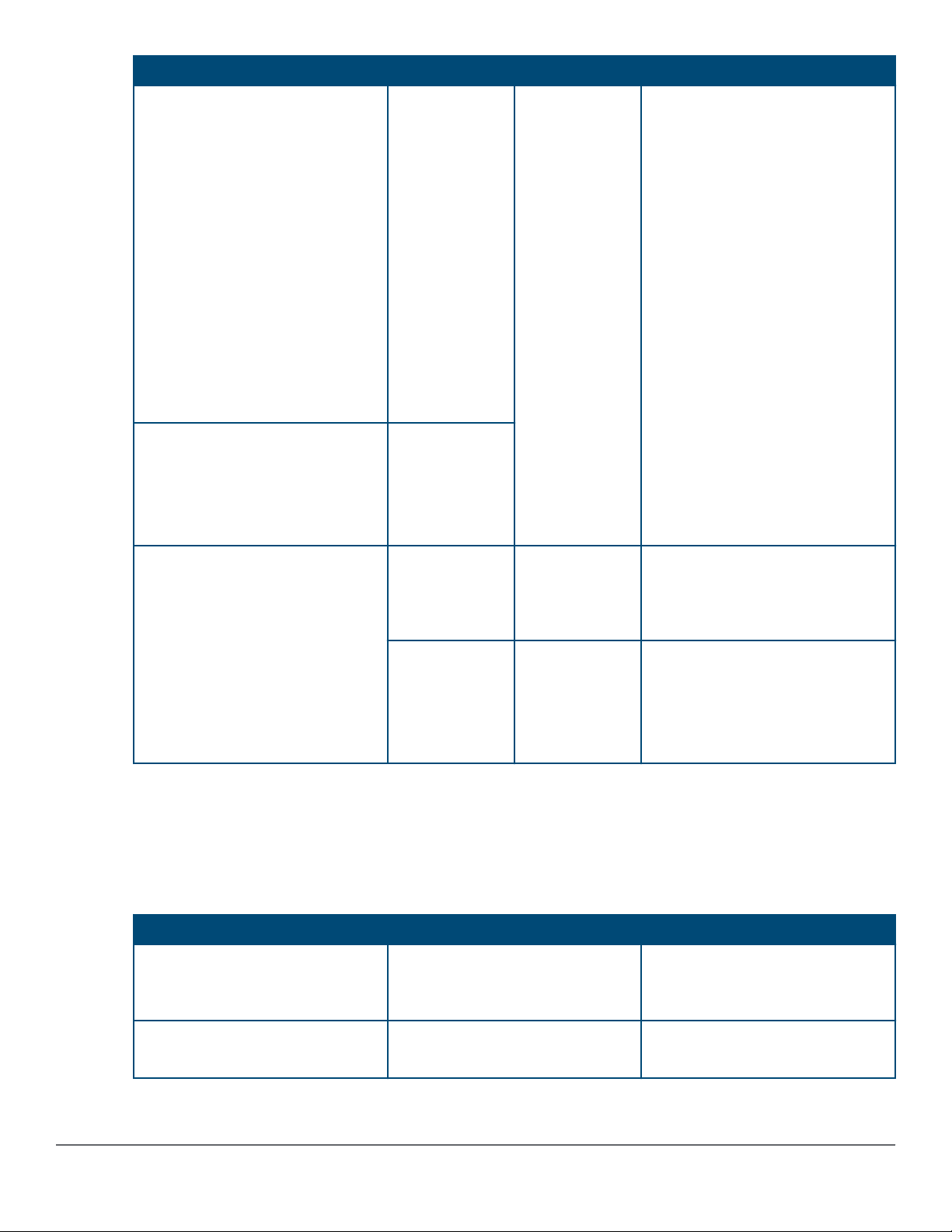
Aruba 2930F switch model Part number Count Included items
JL255A 24G PoE+ Switch
JL261A 24G PoE+ 4SFP Switch
JL263A 24G PoE+ TAA Switch
JL256A 48G PoE+ 4SFP+ Switch
JL262A 48G PoE+ 4SFP+ Switch
JL264A TAA 48G PoE+ 4SFP+
TAA Switch
JL557A 48G PoE+ 4SFP 740W
Switch
JL558A 48G PoE+ 4SFP+ 740W
Switch
JL559A 48G PoE+ 4SFP+ 740W
TAA Switch
JL253A 24G 4SFP+ Switch
JL259A 24G 4SFP Switch
JL254A 48G 4SFP+ Switch
JL260A 48G 4SFP+ Switch
5092-0727 2
5092-0769
Rack mount brackets
4
1
8
4
Rubber foot pads
Cable tie
Small screws; bracket-to-switch
Large screws; bracket-to-rack
JL258A 8G PoE+ Switch 5189-6934 2
4
8
5300-0140 2
8
1
4
Rack mount brackets (long)
Large screws; bracket-to-rack
Small screws; bracket-to-switch
Wall/under-table brackets
Small screws; bracket-to-switch
Cable tie
Rubber foot pads
• There are two warranty documents. One is the HPN warranty and the other is the EG warranty.
◦ 5998-5984 Warranty Statement and Software License
◦ 703828-025 EG Safety, Compliance, and Warranty Information
• Power cord, one of the following:
Country/Region (# option) 370W and non-PoE switches
Argentina (#ARM) J9891A (8121-0729) HPE 1.9m
C13 to IRAM 2073 Power Cord
1
740W switches
J9960A (8121-1481) HPE 2.5m
C15 to IRAM 2073 250V Power
2
Cord
Australia/New Zealand (#ABG) J9883A (8121-0837) HPE 1.9m
C13 to SAA/3 Power Cord
J9941A (8121-1476) HPE 2.5m
C15 to SAA/3 250V Power Cord
Table Continued
20 Aruba 2930F Switch Series Installation and Getting Started Guide
Country/Region (# option) 370W and non-PoE switches
1
740W switches
2
Brazil (#AC4) J9894A (8121-1071) HPE 1.9m
C13 to BR3 10Amp Power Cord
Chile (#A1X) J9886A (8121-0735) HPE 1.9m
C13 to CEI 23-50 Power Cord
China (#AKM) J9890A (8121-0943) HPE 1.9m
C13 to GB 1002 Power Cord
Denmark (#ACE) J9888A (8121-0733) HPE 1.9m
C13 to DK 2 5Amp Power Cord
Europe (#ABB) / South Korea
(#AC6)
J9885A (8121-0731) HPE 1.9m
C13 to CEE 7-xvi Power Cord
India (#AC1) / South Africa (#ACQ) J9892A (8121-0564) HPE 1.9m
C13 to IS 1293 250V Power Cord
Israel (#AKJ) J9899A (8121-1004) HPE 1.9m
C13 to IL-3 90 Degree 250V Power
Cord
J9951A (8121-1265) HPE 2.5m
C15 to BR3 10Amp 250V Power
Cord
J9946A (8121-1477) HPE 2.5m
C15 to CEI 23-50 3-pole 250V
Power Cord
J9949A (8121-1484) HPE 2.5m
C15 to PRC/3 250V Power Cord
J9948A (8121-1486) HPE 2.5m
C15 to DK 2-5A 250V Power Cord
J9945A (8121-1479) HPE 2.5m
C15 to CEE 7-VIIG 250V Power
Cord
J9956A (8121-1483) HPE 2.5m
C15 to ZA/3 250V Power Cord
J9958A (8121-1478) HPE 2.5m
C15 to IL-3 90 Degree 250V Power
Cord
Japan (#ACF) J9893A (8121-1143) HPE 1.9m
C13 to 498GJ JP 3-pole 125V
Power Cord
UK (#ACC) / Hong Kong /
Singapore / Malaysia (#ARE)
J9884A (8121-0739) HPE 1.9m
C13 to BS 1363/A Power Cord
J9950A (8121-1482) HPE 2.5m
C15 to 498GJ JP 3-pole 125V
Power Cord
J9942A (8121-1475) HPE 2.5m
C15 to BS 1363/A 250V Power
Cord
Switzerland (#ACD) J9898A (8121-0738) HPE 1.9m
C13 to SEV 6534-2 Type 12G
250V Power Cord
Taiwan (#ARB) J9887A (8121-0964) HPE 1.9m
C13 to CNS 10917-3 Power Cord
J9957A (8121-1480) HPE 2.5m
C15 to SEV 6534-2 Type 12G
250V Power Cord
J9947A (8121-1511) HPE 2.5m
C15 to TW15CS3 125V Power
Cord
Thailand (#AKL) J9895A (8121-0734) HPE 1.9m
C13 to NEMA 5-15P Power Cord
J9952A (8121-1485)HPE 2.5m
C15 to NEMA 5-15P TH 250V
Power Cord
US / Canada / Mexico (#ABA) J9896A (8121-1141) HPE 1.9m
C13 to NEMA 5-15P NA Power
J9953A (8121-0914) HPE 2.5m
C15 to NEMA 5-15P Power Cord
Cord
1
JL253A, JL254A, JL259A, JL260A, JL255A, JL256A, JL261A, JL262A, JL263A, JL264A
2
JL557A, JL558A, JL559A
PDU Jumper Cord (NA/Japan/Taiwan) J9943A (8121-1091) HPE 2.5m C15 to C14 PDU NA/JP/TW Power
Cord.
Chapter 2 Installing the switch 21

PDU Jumper Cord (other countries) J8844A (8121-1094) HPE 2.5m C15 to C14 PDU Rest of World Power
Cord.
Installation procedures
Procedure
1. Prepare the installation site on page 24.
Ensure the physical environment into which you will be installing the switch is properly prepared, including
having the correct network cabling ready to connect to the switch and having an appropriate location for the
switch. See Installation precautions on page 23 for some installation precautions.
2. Verify the switch passes self test on page 24.
Plug the switch into a power source and observe that the LEDs on the switch’s front panel indicate correct
switch operation. When self test is complete, unplug the switch.
3. Mount the switch on page 27.
The switch can be mounted in a 19-inch telco rack, in an equipment cabinet, or on a horizontal surface. The 8port switch (JL258A) can also be mounted on a wall or under a table.
4. Install or remove SFP/SFP+ transceivers on page 34.
The switch has two or four slots for installing SFP/SFP+ transceivers. Depending on where you install the
switch, it may be easier to install the transceivers first. Transceivers can be hot swapped—they can be
installed or removed while the switch is powered on.
5. Connect the switch to a power source on page 36.
Once the switch is mounted, plug it into the main power source.
6. (Optional) Connect a management console on page 37.
You may want to modify the switch’s configuration, for example, to configure an IP address so it can be
managed using a Web browser, from an SNMP network management station, or through a Telnet session.
Configuration changes can be made by using the included console cable to connect a PC to the switch’s
console port.
7. Connect the network cables on page 40.
Using the appropriate network cables, connect the network devices to the switch ports.
At this point, your switch is fully installed. See the rest of this chapter if you need more detailed information on any
of these installation steps.
22 Aruba 2930F Switch Series Installation and Getting Started Guide
Installation precautions
• The rack or cabinet should be adequately secured to prevent it from becoming unstable and/ or
falling over.
• Devices installed in a rack or cabinet should be mounted as low as possible, with the heaviest
devices at the bottom and progressively lighter devices installed above.
• For a wall-mounted Aruba 2930F 8G PoE+ 2SFP+ Switch (JL258A), face the network ports up,
that is, away from the floor. Do not wall-mount the switch with the network ports facing down
(towards the floor).
• When installing the switch, the AC outlet should be near the switch and should be easily
accessible in case the switch must be powered off.
• Ensure the power source circuits are properly grounded, then use the power cord supplied with
the switch to connect it to the power source.
• Use only approved power cords with your Aruba Networking Product. Please see the power cord
information in the section titled “Included parts” (page 17) of this guide for acceptable power cords
that are appropriate for this product. Failure to use approved power cords can result in personal
injury and product damage, and may void your product warranty.
• Use only the AC/DC power adapter and power cord (if applicable), supplied with the switch. Use
of other adapters or power cords, including those that came with other Hewlett Packard
Enterprise products, may result in damage to the equipment.
• If your installation requires a different power cord than the one supplied with the switch and power
supply, be sure the cord is adequately sized for the switch’s current requirements. In addition, be
sure to use a power cord displaying the mark of the safety agency that defines the regulations for
power cords in your country. The mark is your assurance that the power cord can be used safely
with the switch and power supply.
• When installing the switch, the AC outlet should be near the switch and should be easily
accessible in case the switch must be powered off.
• Ensure the switch does not overload the power circuits, wiring, and over-current protection. To
determine the possibility of overloading the supply circuits, add together the ampere ratings of all
devices installed on the same circuit as the switch and compare the total with the rating limit for
the circuit. The maximum ampere ratings are usually printed on the devices near the AC power
connectors.
• Do not install the switch in an environment where the operating ambient temperature might
exceed its specification. This includes a fully-enclosed rack. Ensure the air flow around the sides
and back of the switch is not restricted. Leave at least 3 inches (7.6 cm) for cooling for the 24and 48-port switch models when installed in a fully-enclosed rack.
NOTE: Normal operating temperature for the JL258A Aruba 2930F 8G PoE+ 2SFP+ Switch
requires wider spacing minimums than described above for the 24– and 48–port switch models.
For rack installation, maintain at least 1U space as a minimum above the product. Also, installing
this switch in an enclosed, confined space such as a small bookshelf or unventilated cabinet is
not recommended.
Chapter 2 Installing the switch 23
Loading...