


 Loading...
Aruba 2530 Switch Series Installation
and Getting Started Guide
Part Number: 5998-7034a |
|
Published: June 2018 |
|
Edition: 2 |
Power over Ethernet |
|

HP 2530 Switch Series
Installation and Getting Started Guide

© Copyright 2014, 2018 Hewlett Packard
Enterprise Development LP
Publication Number
5998-7034a May 2018
Applicable Products
HP 2530-8 Switch |
(J9783A) |
HP 2530-24 Switch |
(J9782A) |
HP 2530-48 Switch |
(J9781A) |
HP 2530-8G Switch |
(J9777A) |
HP 2530-24G Switch |
(J9776A) |
HP 2530-48G Switch |
(J9775A) |
HP 2530-8-PoE+ Switch |
(J9780A) |
HP 2530-24-PoE+ Switch |
(J9779A) |
HP 2530-48-PoE+ Switch |
(J9778A) |
HP 2530-8G-PoE+ Switch |
(J9774A) |
HP 2530-24G-PoE+ Switch |
(J9773A) |
HP 2530-48G-PoE+ Switch |
(J9772A) |
HP 2530-8-POE+ Internal PS |
(JLO70A) |
Switch |
|
Disclaimer
HEWLETT-PACKARD COMPANY MAKES NO WARRANTY OF ANY KIND WITH REGARD TO THIS MATERIAL, INCLUDING, BUT NOT LIMITED TO, THE IMPLIED WARRANTIES OF MERCHANTABILITY AND FITNESS FOR A PARTICULAR PURPOSE. Hewlett-Packard shall not be liable for errors contained herein or for incidental or consequential damages in connection with the furnishing, performance, or use of this material.
The information contained herein is subject to change without notice. The only warranties for HP products and services are set forth in the express warranty statements accompanying such products and services. Nothing herein should be construed as constituting an additional warranty. HP shall not be liable for technical or editorial errors or omissions contained herein.
Hewlett-Packard assumes no responsibility for the use or reliability of its software on equipment that is not furnished by Hewlett-Packard.
Warranty
For the latest license and warranty information, visit www.hp.com/networking/support.
A copy of the specific warranty terms applicable to your Hewlett-Packard products and replacement parts can be obtained from your HP Sales and Service Office or authorized dealer.
Safety
Before installing and operating these products, please read the “Installation Precautions” in chapter 2, “Installing the Switch”, and the safety statements in the General Safety and Regulatory Information booklet included with the product.
Hewlett-Packard Company
8000 Foothills Boulevard, m/s 5551 Roseville, California 95747-5551
www.hp.com/networking

Contents
Contents
1 Introducing the Switch
Front of the Switch . . . . . . . . . . . . . . . . . . . . . . . . . . . . . . . . . . . . . . . . . . . . . . 1-5
Network Ports . . . . . . . . . . . . . . . . . . . . . . . . . . . . . . . . . . . . . . . . . . . . . . 1-6
LEDs . . . . . . . . . . . . . . . . . . . . . . . . . . . . . . . . . . . . . . . . . . . . . . . . . . . . . . 1-6
Port LEDs . . . . . . . . . . . . . . . . . . . . . . . . . . . . . . . . . . . . . . . . . . . . . . 1-8
LED Mode Select Button and Indicator LEDs . . . . . . . . . . . . . . . . 1-9
Reset Button . . . . . . . . . . . . . . . . . . . . . . . . . . . . . . . . . . . . . . . . . . . . . . 1-10
Clear Button . . . . . . . . . . . . . . . . . . . . . . . . . . . . . . . . . . . . . . . . . . . . . . . 1-10
Console Port . . . . . . . . . . . . . . . . . . . . . . . . . . . . . . . . . . . . . . . . . . . . . . 1-10
Back of the Switch . . . . . . . . . . . . . . . . . . . . . . . . . . . . . . . . . . . . . . . . . . . . . 1-11
Power Connector . . . . . . . . . . . . . . . . . . . . . . . . . . . . . . . . . . . . . . . . . . 1-12
Switch Features . . . . . . . . . . . . . . . . . . . . . . . . . . . . . . . . . . . . . . . . . . . . . . . 1-12
Save Power Mode . . . . . . . . . . . . . . . . . . . . . . . . . . . . . . . . . . . . . . . . . . 1-13
2 Installing the Switch
Included Parts . . . . . . . . . . . . . . . . . . . . . . . . . . . . . . . . . . . . . . . . . . . . . . . . . . 2-1
Installation Precautions . . . . . . . . . . . . . . . . . . . . . . . . . . . . . . . . . . . . . . 2-4
Installation Procedures . . . . . . . . . . . . . . . . . . . . . . . . . . . . . . . . . . . . . . . . . |
. 2-5 |
|
1. |
Prepare the Installation Site . . . . . . . . . . . . . . . . . . . . . . . . . . . . . . . . |
2-6 |
2. |
Verify the Switch Passes Self Test . . . . . . . . . . . . . . . . . . . . . . . . . . . |
2-7 |
|
LED Behavior . . . . . . . . . . . . . . . . . . . . . . . . . . . . . . . . . . . . . . . . . . . |
2-8 |
3. |
Mount the Switch . . . . . . . . . . . . . . . . . . . . . . . . . . . . . . . . . . . . . . . . . |
2-9 |
|
Rack or Cabinet Mounting . . . . . . . . . . . . . . . . . . . . . . . . . . . . . . . . |
2-9 |
|
Rack Mounting the Switch . . . . . . . . . . . . . . . . . . . . . . . . . . . . . . . |
2-10 |
|
Wall or Under-Table Mounting . . . . . . . . . . . . . . . . . . . . . . . . . . . . |
2-12 |
|
Horizontal Surface Mounting . . . . . . . . . . . . . . . . . . . . . . . . . . . . . |
2-13 |
4. Connect the Switch to a Power Source . . . . . . . . . . . . . . . . . . . . . . |
2-14 |
|
5. |
Connect the Network Cables . . . . . . . . . . . . . . . . . . . . . . . . . . . . . . . |
2-16 |
|
Using the RJ-45 Connectors . . . . . . . . . . . . . . . . . . . . . . . . . . . . . . |
2-16 |
iii

Contents
6. Installing or Removing SFPs . . . . . . . . . . . . . . . . . . . . . . . . . . . . . . . 2-17 Installing the SFPs: . . . . . . . . . . . . . . . . . . . . . . . . . . . . . . . . . . . . . 2-17 Removing the SFPs . . . . . . . . . . . . . . . . . . . . . . . . . . . . . . . . . . . . . 2-18 Connecting Cables to SFPs . . . . . . . . . . . . . . . . . . . . . . . . . . . . . . . 2-18
7. (Optional) Connect a Console to the Switch . . . . . . . . . . . . . . . . . . 2-18 Terminal Configuration . . . . . . . . . . . . . . . . . . . . . . . . . . . . . . . . . . 2-19 Direct Console Access . . . . . . . . . . . . . . . . . . . . . . . . . . . . . . . . . . . 2-20
Sample Network Topologies . . . . . . . . . . . . . . . . . . . . . . . . . . . . . . . . . . . . . 2-22
As a Desktop Switch Implementing PoE . . . . . . . . . . . . . . . . . . . . . . . 2-22
As a Segment Switch Implementing PoE . . . . . . . . . . . . . . . . . . . . . . . 2-23
Stacking the Switch . . . . . . . . . . . . . . . . . . . . . . . . . . . . . . . . . . . . . . . . . 2-25
3 Configuring the Switch
Recommended Minimal Configuration . . . . . . . . . . . . . . . . . . . . . . . . . . . . . 3-1
Using the Console Setup Screen . . . . . . . . . . . . . . . . . . . . . . . . . . . . . . . 3-2
Where to Go From Here . . . . . . . . . . . . . . . . . . . . . . . . . . . . . . . . . . . . . . 3-3
Using the IP Address for Remote Switch Management . . . . . . . . . . . . . . . . 3-5
Starting a Telnet Session . . . . . . . . . . . . . . . . . . . . . . . . . . . . . . . . . . . . . 3-5
Starting a Web Browser Session . . . . . . . . . . . . . . . . . . . . . . . . . . . . . . . 3-5
4 Troubleshooting
Basic Troubleshooting Tips . . . . . . . . . . . . . . . . . . . . . . . . . . . . . . . . . . . . . . |
4-1 |
Diagnosing with the LEDs . . . . . . . . . . . . . . . . . . . . . . . . . . . . . . . . . . . . . . . . 4-4
LED patterns for General Switch Troubleshooting . . . . . . . . . . . . . . . 4-4
LED Patterns for PoE Troubleshooting . . . . . . . . . . . . . . . . . . . . . . . . . 4-8
Proactive Networking . . . . . . . . . . . . . . . . . . . . . . . . . . . . . . . . . . . . . . . . . . . 4-9
Hardware Diagnostic Tests . . . . . . . . . . . . . . . . . . . . . . . . . . . . . . . . . . . . . . 4-10
Testing the Switch by Resetting It . . . . . . . . . . . . . . . . . . . . . . . . . . . . |
4-10 |
Checking the Switch LEDs . . . . . . . . . . . . . . . . . . . . . . . . . . . . . . . |
4-10 |
Checking Console Messages . . . . . . . . . . . . . . . . . . . . . . . . . . . . . . |
4-10 |
Testing Twisted-Pair Cabling . . . . . . . . . . . . . . . . . . . . . . . . . . . . . . . . . 4-11
Testing Switch-to-Device Network Communications . . . . . . . . . . . . 4-11
Testing End-to-End Network Communications . . . . . . . . . . . . . . . . . 4-11
Restoring the Factory Default Configuration . . . . . . . . . . . . . . . . . . . . . . . 4-12
Downloading New Switch Software . . . . . . . . . . . . . . . . . . . . . . . . . . . . . . 4-13
iv

Contents
HP Customer Support Services . . . . . . . . . . . . . . . . . . . . . . . . . . . . . . . . . . 4-13
Before Calling Support . . . . . . . . . . . . . . . . . . . . . . . . . . . . . . . . . . . . . . 4-13
A Specifications
Switch Specifications . . . . . . . . . . . . . . . . . . . . . . . . . . . . . . . . . . . . . . . . . . . A-1
Physical . . . . . . . . . . . . . . . . . . . . . . . . . . . . . . . . . . . . . . . . . . . . . . . . . . . A-1
Electrical . . . . . . . . . . . . . . . . . . . . . . . . . . . . . . . . . . . . . . . . . . . . . . . . . |
A-2 |
Environmental . . . . . . . . . . . . . . . . . . . . . . . . . . . . . . . . . . . . . . . . . . . . . |
A-3 |
Acoustics . . . . . . . . . . . . . . . . . . . . . . . . . . . . . . . . . . . . . . . . . . . . . . . . . |
A-3 |
Safety . . . . . . . . . . . . . . . . . . . . . . . . . . . . . . . . . . . . . . . . . . . . . . . . . . . . |
A-3 |
Standards . . . . . . . . . . . . . . . . . . . . . . . . . . . . . . . . . . . . . . . . . . . . . . . . . . . . . |
A-4 |
Cabling and Technology Information Specifications . . . . . . . . . . . . . . . . |
A-5 |
Technology Distance Specifications . . . . . . . . . . . . . . . . . . . . . . . . . . . |
A-6 |
Mode Conditioning Patch Cord . . . . . . . . . . . . . . . . . . . . . . . . . . . . . . . . . . |
A-7 |
Installing the Patch Cord . . . . . . . . . . . . . . . . . . . . . . . . . . . . . . . . . . . . |
A-7 |
Twisted-Pair Cable/Connector Pin-Outs . . . . . . . . . . . . . . . . . . . . . . . . . . . A-9
Straight-through Twisted-Pair Cable for
10 Mbps or 100 Mbps Network Connections . . . . . . . . . . . . . . . . . . . A-11 Cable Diagram . . . . . . . . . . . . . . . . . . . . . . . . . . . . . . . . . . . . . . . . A-11 Pin Assignments . . . . . . . . . . . . . . . . . . . . . . . . . . . . . . . . . . . . . . . A-11
Crossover Twisted-Pair Cable for
10 Mbps or 100 Mbps Network Connection . . . . . . . . . . . . . . . . . . . . A-12 Cable Diagram . . . . . . . . . . . . . . . . . . . . . . . . . . . . . . . . . . . . . . . . A-12 Pin Assignments . . . . . . . . . . . . . . . . . . . . . . . . . . . . . . . . . . . . . . . A-12
Straight-Through Twisted-Pair Cable for
1000 Mbps Network Connections . . . . . . . . . . . . . . . . . . . . . . . . . . . . A-13 Cable Diagram . . . . . . . . . . . . . . . . . . . . . . . . . . . . . . . . . . . . . . . . A-13 Pin Assignments . . . . . . . . . . . . . . . . . . . . . . . . . . . . . . . . . . . . . . . A-13
B Safety and EMC Regulatory Statements
Safety Information . . . . . . . . . . . . . . . . . . . . . . . . . . . . . . . . . . . . . . . . . . . . . |
B-1 |
Informations concernant la sécurité . . . . . . . . . . . . . . . . . . . . . . . . . . . . . . B-2
Hinweise zur Sicherheit . . . . . . . . . . . . . . . . . . . . . . . . . . . . . . . . . . . . . . . . . B-3
Considerazioni sulla sicurezza . . . . . . . . . . . . . . . . . . . . . . . . . . . . . . . . . . . |
B-4 |
Consideraciones sobre seguridad . . . . . . . . . . . . . . . . . . . . . . . . . . . . . . . . |
B-5 |
v

Contents
Safety Information (Japan) . . . . . . . . . . . . . . . . . . . . . . . . . . . . . . . . . . . . . . B-6
Safety Information (China) . . . . . . . . . . . . . . . . . . . . . . . . . . . . . . . . . . . . . . B-7
EMC Regulatory Statements . . . . . . . . . . . . . . . . . . . . . . . . . . . . . . . . . . . . . B-8
U.S.A. . . . . . . . . . . . . . . . . . . . . . . . . . . . . . . . . . . . . . . . . . . . . . . . . . . . . B-8
Canada . . . . . . . . . . . . . . . . . . . . . . . . . . . . . . . . . . . . . . . . . . . . . . . . . . . B-8
Australia/New Zealand . . . . . . . . . . . . . . . . . . . . . . . . . . . . . . . . . . . . . . B-8
Japan . . . . . . . . . . . . . . . . . . . . . . . . . . . . . . . . . . . . . . . . . . . . . . . . . . . . . B-8
Korea . . . . . . . . . . . . . . . . . . . . . . . . . . . . . . . . . . . . . . . . . . . . . . . . . . . . . B-9
Taiwan . . . . . . . . . . . . . . . . . . . . . . . . . . . . . . . . . . . . . . . . . . . . . . . . . . . B-9
Index
vi
1
Introducing the Switch
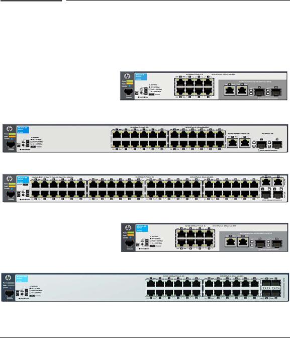
The HP 2530 Switch Series are multiport switches that can be used to build high-performance switched workgroup networks. These switches are store- and-forward devices that offer low latency for high-speed networking. Six of the switches also support the IEEE 802.3at standard for providing PoE+ power to connected devices.
HP 2530-8 Switch (J9783A)
HP 2530-24 Switch (J9782A)
HP 2530-48 Switch (J9781A)
HP 2530-8G Switch (J9777A)
HP 2530-24G Switch (J9776A)
1-1

Introducing the Switch
HP 2530-48G Switch (J9775A)
HP 2530-8-PoE+ Switch (J9780A)
HP 2530-8-PoE+ Internal PS Switch (JLO70A)
HP 2530-24-PoE+ Switch (J9779A)
HP 2530-48-PoE+ Switch (J9778A)
HP 2530-8G-PoE+ Switch (J9774A)
HP 2530-24G-PoE+ Switch (J9773A)
1-2
Introducing the Switch
HP 2530-48G-PoE+ Switch (J9772A)
Throughout this manual, these switches will be referred to as the 2530-8, 253024, 2530-48, 2530-8G, 2530-24G, 2530-48G, 2530-8-PoE+, 2530-24-PoE+, 2530- 48-PoE+, 2530-8G-PoE+, 2530-24G-PoE+, and 2530-48G-PoE+.
■The 2530-8 and 2530-8-PoE+ switches have 8 auto-sensing 10/100BASETX RJ-45 ports, and two Gigabit dual-personality ports (ports 9 and 10)
■The 2530-24 and 2530-24-PoE+ switches have 24 auto-sensing 10/ 100BASE-TX RJ-45 ports, two 10/100/1000BASE-T RJ-45 ports (ports 25 and 26), and two SFP slots for supported HP SFP transceivers (ports 27 and 28)
■The 2530-48 and 2530-48-PoE+ switches have 48 auto-sensing 10/ 100BASE-TX RJ-45 ports, two 10/100/1000BASE-T RJ-45 ports (ports 49 and 50), and two SFP slots for supported HP SFP transceivers (ports 51 and 52)
■The 2530-8G and 2530-8G-PoE+ switches have 8 auto-sensing 10/100/ 1000BASE-T RJ-45 ports, and two Gigabit dual-personality ports (ports 9 and 10)
■The 2530-24G and 2530-24G-PoE+ switches have 24 auto-sensing 10/100/ 1000BASE-T RJ-45 ports, and four SFP slots for supported HP SFP transceivers (ports 25-28).
■The 2530-48G and 2530-48G-PoE+ switches have 48 auto-sensing 10/100/ 1000BASE-T RJ-45 ports, and four Small Form Factor Pluggable (SFP) slots for supported HP SFP transceivers (ports 49-52)
■Power-over-Ethernet or PoE power - The HP 2530 PoE+ switches support the IEEE 802.3at standard, which allows IP telephones, wireless LAN Access Points, and other appliances to receive power as well as data over existing LAN cabling, without needing to modify the existing Ethernet infrastructure.
■The HP 2530 PoE+ switches are designed with an internal PoE power supply capable of providing 370 watts of PoE power (HP 2530 48-port switches), 190 watts (HP 2530 24-port switches), or 62 watts (HP 2530 8- port switches). Each switch port can provide up to 30 watts (7.5 watts if all ports are used) of PoE power to connected devices. For further
1-3

Introducing the Switch
information regarding PoE power, see the HP Power over Ethernet (PoE/ PoE+) Planning and Implementation Guide, which is on the HP Web site at www.hp.com/networking/support.
■Dual-personality ports - These ports use either the 10/100/1000BASE-T RJ-45 connector, or a supported HP SFP transceiver for fiber-optic connection. By default, the RJ-45 connectors are enabled.
These switches can be directly connected to computers, printers, and servers to provide dedicated bandwidth to those devices, and you can build a switched network infrastructure by connecting the switch to hubs, other switches, or routers. In addition, these switches can be fully managed by HP SNMP-based and browser-based network management tools.
Using HP SFPs, these products support optional network connectivity with the following speeds and technologies:
Table 1-1. Optional Network Connectivity, Speeds and Technologies
|
|
|
Transceiver Form- |
|
|
|
|
Factor and |
|
|
|
|
Connector1 |
|
Speed |
Technology |
Cabling |
SFP Connector |
|
|
|
|
|
|
100 Mbps |
100-FX |
Fiber (multimode) |
LC |
|
|
|
|
||
100-BX |
Fiber (single mode) |
LC |
||
|
||||
|
|
|
|
|
|
1000-T |
Copper (twisted-pair) |
RJ-45 |
|
|
|
|
|
|
|
1000-SX |
Fiber (multimode) |
LC |
|
|
|
|
|
|
1 Gbps |
1000-LX |
Fiber (multimode or single mode) |
LC |
|
|
|
|
|
|
|
1000-LH |
Fiber (single mode) |
LC |
|
|
|
|
|
|
|
1000-BX |
Fiber (single mode) |
LC |
|
|
|
|
|
1 For supported transceivers, visit www.hp.com/networking/support.
– In the first textbox, type J4858 (for 100-Mb and Gigabit information).
– Select any of the products that display in the dropdown list. Then click Display selected.
– Select Product support information. Then click Manuals and find the Transceiver Support Matrix.
For technical details of cabling and technologies see “Cabling and Technology Information Specifications” in the appendix A.
1-4
Introducing the Switch
Front of the Switch
Front of the Switch
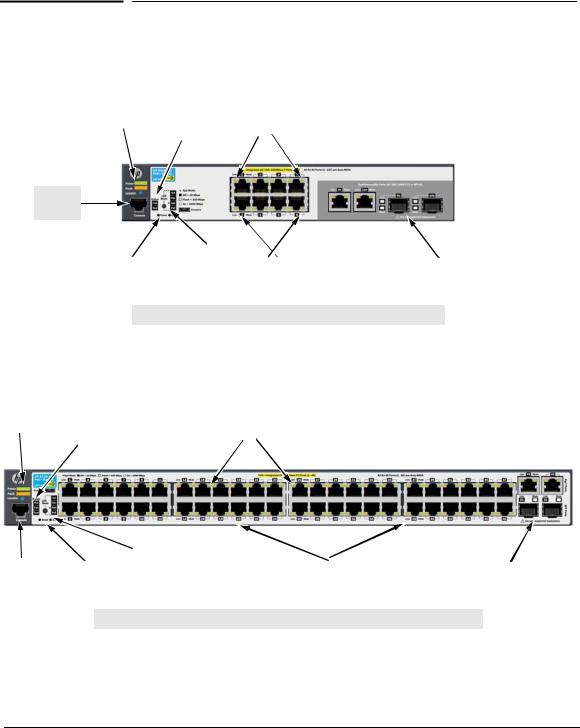
The following image represents the characteristics of all of the HP 2530 8-port Gigabit Ethernet and Fast Ethernet switches.
Power, |
|
|
|
|
HP 2530-8G-PoE+ Switch (J9774A) |
Fault, and |
|
|
|
|
|
|
Test and |
|
|
|
|
Locator |
|
|
|
|
|
|
|
Switch port LEDs |
|
||
LEDs |
|
Status LEDs |
|
|
|
|
|
|
|
|
|
Console
Port
Reset and |
|
LED Mode select |
|
10/100/1000BASE-T |
|
Dual-personality ports |
Clear |
|
button and |
|
RJ-45 PoE+ ports1 |
|
(10/100/1000BASE-T or SFP) |
buttons |
|
indicator LEDs |
|
|
|
|
|
|
|
|
|
||
|
|
|
|
|
|
|
1 All 10/100/1000BASE-T RJ-45 ports have the Auto-MDIX feature.
The following image represents the characteristics of the HP 2530 24-port and 48-port Fast Ethernet switches.
Power, |
|
|
|
|
HP 2530-48-PoE+ Switch (J9778A) |
Fault, and |
|
|
|
|
|
Locator |
|
|
|
|
|
|
Test and Status LEDs |
|
Switch port LEDs |
|
|
LEDs |
|
|
|
||
|
|
|
|
|
|
Console |
|
Reset and |
|
LED Mode select button |
|
10/100BASE-TX RJ-45 PoE+ ports1 |
|
Two 10/100/1000BASE-T ports1 |
Port |
|
Clear |
|
and indicator LEDs |
|
|
|
and two SFP slots |
|
|
|
||||||
|
|
buttons |
|
|
|
|
|
|
|
|
|
|
|
|
|
|
|
|
|
|
|
|
|
|
|
|
1 All 10/100BASE-TX and 10/100/1000BASE-T RJ-45 ports have the Auto-MDIX feature.
1-5
Introducing the Switch
Front of the Switch
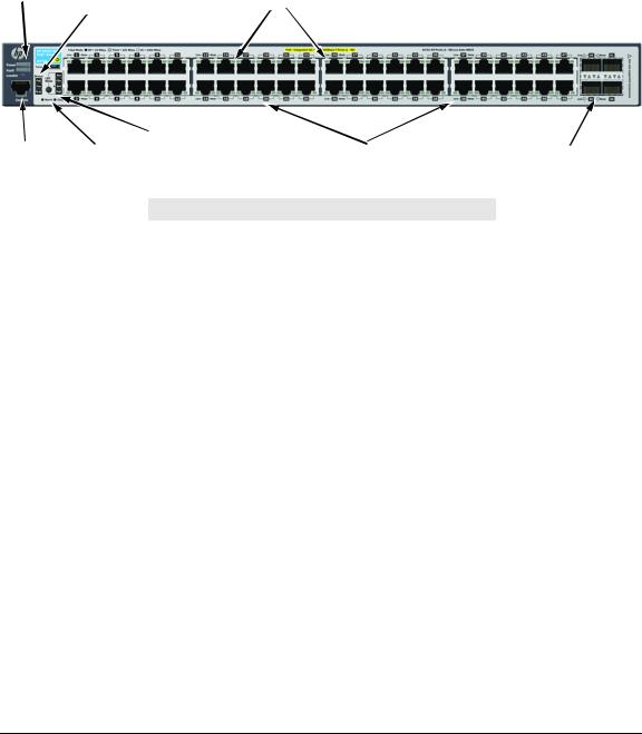
The following image represents the characteristics of the HP 2530 24-port and 48-port Gigabit Ethernet switches.
Power, |
|
|
|
|
HP 2530-48G-PoE+ Switch (J9772A) |
Fault, and |
|
|
|
|
|
Locator |
|
|
|
|
|
|
Test and Status LEDs |
|
Switch port LEDs |
|
|
LEDs |
|
|
|
||
|
|
|
|
|
|
Console |
|
Reset and |
|
LED Mode select button |
|
10/100/1000BASE-T RJ-45 PoE+ ports1 |
|
SFP slots |
Port |
|
Clear |
|
and indicator LEDs |
|
|
|
|
|
|
|
|
|
||||
|
|
buttons |
|
|
|
|
|
|
|
|
|
|
|
|
|
|
|
|
|
|
|
|
|
|
|
|
1 All 10/100/1000BASE-T RJ-45 ports have the Auto-MDIX feature.
Network Ports
■8, 24, or 48 auto-sensing 10/100BASE-TX or 10/100/1000BASE-T ports. All these ports have the “Auto-MDIX” feature, which means that you can use either straight-through or crossover twisted-pair cables to connect any network devices to the switch.
■Two dual-personality ports (HP 2530 8-port switches).
■Two auto-sensing 10/100/1000BASE-T ports and two SFP slots for fiber or copper uplinks (HP 2530 24-port and 48-port Fast Ethernet switches).
■Four SFP slots for fiber or copper uplinks (HP 2530 24-port and 48-port Gigabit Ethernet switches).
LEDs
On the 2530 Switches, there are three groupings of LEDs:
■switch status LEDs (Table 1-2)
■port LEDs (Table 1-3)
■Port LED Mode indicator LEDs (near the selector button) (Table 1-4)
1-6

|
|
Introducing the Switch |
|
|
Front of the Switch |
Table 1-2. Switch Status LEDs |
||
|
|
|
Switch LEDs |
State |
Meaning |
|
|
|
Power |
On |
The internal power supply is working properly. |
(green) |
Off |
No power connection. The switch is NOT receiving power. |
|
||
|
|
|
Fault |
Off |
The normal state; indicates there are no fault conditions on the switch. |
(orange) |
Flashing2 |
A fault has occurred with a component on the switch. The Status LED for |
|
||
|
|
the component with the fault will flash simultaneously. |
|
On |
On briefly after the switch is powered on or reset, at the beginning of |
|
|
switch self test. If this LED is on for a prolonged time, the switch has |
|
|
encountered a fatal hardware failure, or has failed its self test. See |
|
|
chapter 4, “Troubleshooting” for more information. |
|
|
|
Locator |
On |
The Locator LED is used to locate a specific switch in an area full of |
(blue) |
Flashing |
switches. The LED can be set to be on solid or flash for a specified number |
|
Off |
of minutes (1-1440). The default is 30 minutes. Use the command |
|
|
“chassislocate”. |
|
|
|
PoE |
On green |
Normal operation. The switch is ready to supply PoE power. |
(green/orange) |
|
|
|
Flashing |
One or more ports has experienced a fault condition for PoE delivery. The |
|
orange2 |
Fault LED will be flashing simultaneously. If it is a self test failure, the Test |
|
|
LED will be flashing simultaneously. When the switch is put in PoE LED |
|
|
Mode, the Mode LED for the port with the problem will also be flashing |
|
|
simultaneously. |
|
Flashing |
One or more ports has an alert condition for PoE delivery, for example, an |
|
orange1 |
oversubscription condition (not enough PoE power available). Only this |
|
|
LED will be flashing, the Fault LED is off. When the switch is put in PoE |
|
|
LED Mode, the Mode LEDs for the ports with the alert condition will also |
|
|
be flashing. |
|
|
|
Fan |
On green |
The cooling fan is operating normally. |
(green/orange) |
Flashing |
The cooling fan has failed. The switch Fault LED will be flashing |
|
||
|
orange2 |
simultaneously. |
Test |
Off |
The normal operational state; the switch is not undergoing self test. |
(green/orange) |
On green |
The switch self test and initialization are in progress after the switch has |
|
||
|
|
been power cycled or reset. The switch is not operational until this LED |
|
|
goes off. The Test LED also comes on briefly when you “hot swap” an SFP |
|
|
into the switch; the SFP is tested when it is hot swapped. |
|
Flashing |
A component of the switch has failed its self test. The switch Fault LED, |
|
orange2 |
Test LED, and the failed component LED will flash simultaneously. |
1 The flashing behavior is an on/off cycle once every 0.8 seconds approximately, a fast flash. |
||
2 The flashing behavior is an on/off cycle once every 1.6 seconds approximately, a slow flash. |
||
1-7

Introducing the Switch
Front of the Switch
Port LEDs
The port LEDs provide information about the individual switch ports.
Table 1-3. Port LEDs
Switch LEDs |
State |
Meaning |
|
|
|
|
|
Port LEDs |
|
|
|
|
|
|
|
Link2 |
On |
|
The port is enabled and receiving a link indication from the connected |
(green) |
|
|
device. In PoE mode, indicates that the port is configured to enable PoE |
|
|
|
power delivery to the connected device. |
|
|
|
|
|
Off |
|
One of these condition exists: |
|
|
|
• no active network cable is connected to the port |
|
|
|
• the port is not receiving link beat or sufficient light |
|
|
|
• the port has been disabled through the switch console, the Web |
|
|
|
browser interface, HP PCM, or other network management tool. |
|
|
|
• In PoE mode, indicates that the port is configured such that PoE power |
|
|
|
delivery is disabled. |
|
|
|
• Save power mode is enabled. |
|
|
|
|
|
Flashing1 |
The port has failed self test. The switch Fault, and Self Test LEDs will flash |
|
|
|
|
simultaneously. |
|
|
|
|
Mode (green)2 |
Depending on the mode selected, displays the following: |
||
|
• |
network activity information |
|
|
• |
connection duplex mode |
|
|
• |
connection speed information |
|
|
• PoE power delivery status |
||
|
See “LED Mode Select Button and Indicator LEDs:” below for more information. |
||
|
|
|
|
SFP LEDs |
|
|
|
|
|
|
|
Link2 |
Flashing |
One of the following conditions exist: |
|
|
green |
• the SFP is not supported by the current switch software |
|
|
|
|
• the SFP is not a genuine HP SFP and is not supported |
|
|
|
• the SFP is an “A” version in a switch that requires a “B” version or later. |
|
|
|
|
Link and Mode2 |
On for 2 |
Both the Link and Mode LED turn on solid for 2 seconds and then go to |
|
(green) |
seconds |
normal operation. This indicates the SFP has been recognized by the |
|
|
|
|
switch. |
|
|
|
|
1 The flashing behavior is an on/off cycle once every 1.6 seconds, approximately.
2 These LEDs are turned off when Save Power mode is enabled. If Save Power mode is enabled and the LEDs are turned off, they can be turned on temporarily through the LED Mode button.
1-8
Introducing the Switch
Front of the Switch
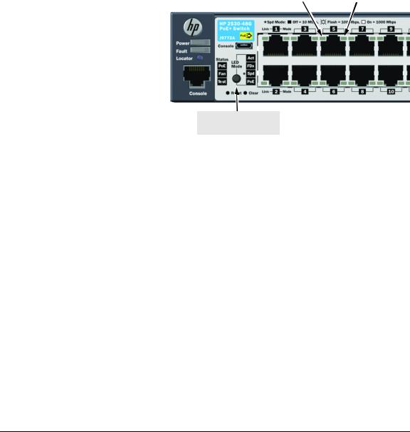
LED Mode Select Button and Indicator LEDs
To optimize the amount of information that can be displayed for each of the switch ports in the limited space available, the HP 2530 Switches use multipledisplay LEDs for each port.
The HP 2530 Switches have two LEDs per port. The Link LED shows the port link status in all modes except PoE mode. In PoE mode, it shows whether the port is configured to provide PoE power. The operation of the Mode LED is controlled by the LED Mode select button, and the current setting is indicated by the LED Mode indicator LEDs near the button. Press the button to step from one view mode to the next. The default view is
Activity (Act).
Link LED |
|
Mode LED |
|
|
|
LED Mode select button and indicator LEDs
Table 1-4. |
Multiple-Display Port LEDs |
||
|
|
|
|
Switch LEDs |
Mode |
|
Meaning |
|
|
|
|
Port Mode |
Act |
|
Indicates the Port LEDs are displaying network activity information. |
indicator LEDs |
|
|
|
FDx |
|
Indicates the Port LEDs are lit for ports that are in full-duplex mode. |
|
(4 green LEDs) |
|
||
|
|
|
|
|
Spd |
|
Indicates the Port LEDs are displaying the connection speed at which each |
|
|
|
port is operating: |
|
|
|
• if the Port LED is off, the port is operating at 10 Mbps. |
|
|
|
• if the Port LED is flashing, the port is operating at 100 Mbps. |
|
|
|
• if the Port LED is on continuously, the port is operating at 1000 Mbps. |
|
|
|
|
|
PoE |
|
Indicates the Port LEDs are lit for ports that are providing PoE power to the |
|
|
|
connected device. |
|
|
|
|
When Save Power mode is enabled and all port LEDs are off, press the LED Mode select button to turn the port LEDs on. Press the LED Mode select button again to step through each view mode. Press the LED Mode select button after the PoE view mode to turn LEDs off.
If the port LEDs are left on when Save Power mode is enabled, they turn off automatically after 10 minutes.
1-9

Introducing the Switch
Front of the Switch
Reset Button
This button is for:
■Resetting the switch - When the switch is powered on. This action clears any temporary error conditions that may have occurred and executes the switch self test.
■Restoring Factory Default Configuration - When pressed with the Clear button in a specific pattern, any configuration changes you may have made through the switch console, the Web browser interface, and SNMP management are removed, and the factory default configuration is restored to the switch. For the specific method to restore the factory default configuration, see “Restoring the Factory Default Configuration” on page 4-12 of this manual.
Clear Button
This button is used for:
■Deleting Passwords - When pressed by itself for at least one second, the button deletes any switch console access passwords that you may have configured. Use this feature if you have misplaced the password and need console access. This button is provided as a convenience, however if you are concerned with the security of the switch configuration and operation, you should make sure the switch is installed in a secure location. This button can be disabled by a CLI command.
■Restoring Factory Default Configuration - See Reset Button above.
Console Port
This port is used to connect a console to the switch by using the RJ-45 to DB9 cable, supplied with the switch. This connection is described under “7. (Optional) Connect a Console to the Switch” on page 2-20 in chapter 2, “Installing the Switch.” The console can be a PC or workstation running a VT100 terminal emulator, or a VT-100 terminal.
You can also connect a console to the switch using the Micro USB console port (cable not provided). Use a USB 2.0 high-speed cable with male type A (4-pin) to male micro-B (5-pin) connectors. The maximum allowable length is 5 meters.
1-10
Introducing the Switch
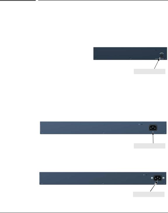
Back of the Switch
Back of the Switch
HP 2530-8 Switch (J9783A)
HP 2530-8G Switch (J9777A)
HP 2530-8-PoE+ Switch (J9780A)
HP 2530-8G-PoE+ Switch (J9774A)
DC power connector
HP 2530-24 Switch (J9782A)
HP 2530-48 Switch (J9781A)
HP 2530-24G Switch (J9776A)
HP 2530-48G Switch (J9775A)
HP 2530-24-PoE+ Switch (J9779A)
HP 2530-24G-PoE+ Switch (J9773A)
AC power connector
HP 2530-48-PoE+ Switch (J9778A)
HP 2530-48G-PoE+ Switch (J9772A)
AC power connector
1-11

Introducing the Switch
Switch Features
HP 2530-8-PoE+ Internal PS Switch (JLO70A)
DC power connector
Power Connector
The HP 2530 24-port and 48-port switches do not have a power switch; they are powered on when connected to an active AC power source. The switches automatically adjust to any voltage between 100-127 and 200-240 volts and either 50 or 60 Hz. There are no voltage range settings required.
The HP 2530 8-port switches do not have a power switch, they are powered on when the external AC/DC power adapter is connected to the switch and to a power source. The external AC/DC power adapter supplies 12 volts DC or 54 volts DC (for PoE+ switches) to the switch and automatically adjusts to any AC voltage between 100-240 volts and either 50 or 60 Hz. No voltage range settings are required.
Switch Features
The features of the HP 2530 Switches include:
■8, 24, or 48 auto-sensing 10/100/1000BASE-T RJ-45 ports with Auto-MDIX, or 8, 24, or 48 auto-sensing 10/100BASE-TX RJ-45 ports with Auto-MDIX.
■Two dual-personality ports (HP 2530 8-port switches).
■Two auto-sensing 10/100/1000BASE-T ports and two SFP uplink slots supporting HP SFP transceivers (HP 2530 24-port and 48-port Fast Ethernet switches).
■Four SFP uplink slots supporting HP SFP transceivers (HP 2530 24-port and 48-port Gigabit Ethernet switches).
1-12
Introducing the Switch
Switch Features
■PoE+ operation—the switches are IEEE 802.3at compliant and provide up to 30W per port to power IP phones, wireless access points, Web cameras, and more. For more information, see the HP Power over Ethernet (PoE/PoE+) Planning and Implementation Guide, which is on the HP Web site at www.hp.com/networking/support.
■The switches support some pre-standard PoE devices. However, the use of a cross-over cable may be required.
■Plug-and-play networking—all ports are enabled—just connect the network cables to active network devices and your switched network is operational.
■Auto-MDIX on all twisted-pair ports, meaning that all twisted-pair connections can be made using straight-through cables. Cross-over cables are not required, although they will also work.
■Automatic learning of the hardware addresses in each switch’s 16000address forwarding table, (with configurable address aging value).
■Automatically negotiated full-duplex operation for the 10/100/1000 RJ-45 ports when connected to other auto-negotiating devices.
■A “Save Power” mode option that keeps port LEDs turned off except for when the LED Mode select button is pressed.
■An automatic low-power mode for ports when a link is not present.
■Easy management of the switches through several available interfaces:
•Console interface — a full featured, easy to use, VT-100 terminal interface that is especially good for out-of-band switch management or for Telnet access to the switch.
•Web browser interface — an easy to use built-in graphical interface that can be accessed from common Web browsers.
•SNMP-based network management:
–HP PCM/PCM+ — a graphical network management tool that you can use to manage your entire small to medium-sized network.
–Intelligent Management Center (IMC) — the HP graphics network management tool intended to manage any sized network. IMC support for the HP 2530 switches is planned for early 2013. Go to www.hp.com/networking to check on support availability.
■Support for the Spanning Tree Protocol to eliminate network loops.
■Support for up to 512 IEEE 802.1Q-compliant VLANs so you can divide the attached end nodes into logical groupings that fit your business needs.
■Download of new switch software for product enhancements or bug fixes.
■Variable speed fans ensure quiet operation.
1-13

Introducing the Switch
Switch Features
■Support for many advanced features to enhance network performance. For a description, see the Management and Configuration Guide, which is on the HP Web site at www.hp.com/networking/support. (You may want to bookmark this Web page for easy access in the future.)
Save Power Mode
A Save Power mode feature can be configured through the console. Save Power mode can be used to turn off port LEDs unless the LED Mode button is pressed. In addition, it can configure the LAN ports to operate at low power if a link is not detected.
1-14

2
Installing the Switch
This chapter provides installation information for the HP 2530 Switches.
Included Parts
The HP 2530 Switches have the following components:
■Documentation kit
•Switch Quick Setup Guide
•Safety and Regulatory information
•Software License, Warranty, and Support information
■Console port serial cable (DB-9 to RJ-45)
■Accessory kits:
2530-8 Switch
2530-8G Switch
2530-8-PoE+ Switch
2530-8G-PoE+ Switch
Kit number 5066-2232
Contains:
•two rack mounting brackets
•eight 8-mm M4 screws to attach the mounting brackets to the switch
•four 5/8-inch number 12-24 screws to attach the switch to a rack
•four rubber feet
Kit number 5066-0621
Contains:
•three 3/4” (20-mm M4) screws for wall and under-table mounting
•three wall anchors
•cable tie for power cord
2-1

Installing the Switch
Included Parts
2530-24-PoE+ Switch |
2530-24 Switch |
2530-24G-PoE+ Switch |
2530-24G Switch |
2530-48-PoE+ Switch |
2530-48 Switch |
2530-48G-PoE+ Switch |
2530-48G Switch |
Kit number 5066-2231
Contains:
•two rack mounting brackets
•two wall/table mounting brackets
•eight 8-mm M4 screws to attach the mounting brackets to the switch
•four 5/8-inch number 12-24 screws to attach the switch to a rack
•four rubber feet
Kit number 5069-6535
Contains:
•two wall/table mounting brackets
•eight 8-mm M4 screws to attach the mounting brackets to the switch
•four 5/8-inch number 12-24 screws to attach the switch to a rack
•four rubber feet
The HP 2530-8-POE+ Internal PS have the following components:
Kit number 5066-4818
Contains:
•two large rack mounting brackets
•two small rack mounting brackets
•eight 8-mm M4 screws to attach the mounting brackets to the switch
•four 5/8-inch number 12-24 screws to attach the switch to a rack
•four rubber feet
Kit number 5069-0621
Contains:
•two wall/table mounting brackets
•eight 8-mm M4 screws to attach the mounting brackets to the switch
•four 5/8-inch number 12-24 screws to attach the switch to a rack
•four rubber feet
2-2

Installing the Switch
Included Parts
■24and 48-port switch AC power cords, one of the following:
|
HP 2530-24, |
|
|
HP 2530-48, |
HP 2530-48-PoE+ and |
Country/Region |
HP 2530-24G, |
|
|
HP 2530-48G, |
HP 2530-48G-PoE+1 |
|
HP 2530-24-PoE+, |
|
|
and |
|
|
HP 2530-24G-PoE+ |
|
|
|
|
Argentina |
8120-6869 |
8120-8375 |
Australia/New Zealand |
8121-0834 |
8121-0857 |
Brazil |
8121-1069 |
8121-1132 |
Chile |
8120-6980 |
8120-8389 |
China |
8120-8377 |
8121-1034 |
Continental Europe |
8120-6802 |
8120-5336 |
Denmark |
8120-6806 |
8120-5340 |
India |
8121-0780 |
8120-5341 |
Israel |
8121-1035 |
8121-1009 |
Japan |
8120-6804 |
8120-5342 |
Malaysia |
8120-6809 |
8120-5334 |
Switzerland |
8120-6807 |
8120-5339 |
South Africa |
8121-0919 |
8120-5341 |
South Korea |
8120-6811 |
8120-5336 |
Taiwan |
8121-0964 |
8121-0967 |
Thailand |
8121-0673 |
8121-0671 |
United Kingdom/Hong Kong/Singapore |
8120-6809 |
8120-5334 |
United States/Canada/Mexico |
8120-6805 |
8121-0973 |
1 The cord for the HP 2530-48-PoE+ and 2530-48G-PoE+ Switches supports a higher amperage and uses a C15 connector.
2-3

Installing the Switch
Included Parts
■8-port switch external AC/DC power adapters and power cords, one of the following:
|
HP 2530-8 |
HP 2530-8G |
HP 2530-8- |
Country/Region |
|
|
PoE+ and |
|
|
|
HP 2530-8G- |
|
|
|
PoE+ |
|
|
|
|
Universal AC/DC Power Adapter |
|
5066-2695 |
|
All countries/regions |
5066-1122 |
5066-2164 |
|
Power Cords |
|
|
|
Argentina |
8120-8367 |
8120-8367 |
8120-6869 |
Australia/New Zealand |
8121-0870 |
8121-0870 |
8121-0834 |
Brazil |
8121-1081 |
8121-1081 |
8121-1069 |
Chile |
8121-0514 |
8121-0514 |
8120-6980 |
China |
8120-8373 |
8120-8373 |
8120-8377 |
Continental Europe |
8120-6314 |
8120-6314 |
8120-6802 |
Denmark |
8120-6314 |
8120-6314 |
8120-6806 |
India |
8121-0702 |
8121-0702 |
8121-0780 |
Israel |
8120-6314 |
8120-6314 |
8121-1035 |
Japan |
8120-6316 |
8120-6316 |
8120-6804 |
Malaysia |
8120-8699 |
8120-8699 |
8120-6809 |
Switzerland |
8120-6314 |
8120-6314 |
8120-6807 |
South Africa |
8120-6317 |
8120-6317 |
8121-0919 |
South Korea |
8120-6314 |
8120-6314 |
8120-6811 |
Taiwan |
8121-0963 |
8121-0963 |
8121-0964 |
Thailand |
8121-0664 |
8121-0664 |
8121-0673 |
United Kingdom/Hong Kong/Singapore |
8120-8699 |
8120-8699 |
8120-6809 |
United States/Canada/Mexico |
8120-6313 |
8120-6313 |
8120-6805 |
2-4

Installing the Switch
Included Parts
■The HP 2530-8-POE+ Internal Power Supply, one of the following:
HP 2530-8-POE+
Country/Region Internal Power
Supply Switch
Power Cords |
|
Argentina |
8120-6871 |
Australia/New Zealand |
8120-6803 |
Brazil |
8120-8944 |
Chile |
8120-6979 |
China |
8120-8377 |
Continental Europe |
8120-6802 |
Denmark |
8120-6806 |
India |
8121-0772 |
Israel |
8121-1005 |
Japan |
8120-6804 |
Malaysia |
8120-8709 |
Switzerland |
8120-6807 |
South Africa |
8120-6808 |
South Korea |
8120-6802 |
Taiwan |
8121-0971 |
Thailand |
8121-0667 |
United Kingdom/Hong Kong/Singapore |
8120-6801 |
United States/Canada/Mexico |
8120-6805 |
■Optional accessories for HP 2530 8-port switches:
•A cable guard (HP P/N J9700A) to provide security for the attached network cables.
•A power shelf (HP P/N J9820A) to hold the AC/DC power adapter, not compatible with HP 2530-8-PoE+ Internal Power Supply switch (HP P/N J9L070A).
■Optional accessory for HP 2530 24-port and 48-port switches:
•HP X410 Switch Rail Kit (J9583A).
J a p a n P o w e r
C o r d W a r n i n g
2-5

Installing the Switch
Included Parts
W A R N I N G
C a u t i o n s
Installation Precautions
■The rack or cabinet should be adequately secured to prevent it from becoming unstable and/or falling over.
Devices installed in a rack or cabinet should be mounted as low as possible, with the heaviest devices at the bottom and progressively lighter devices installed above.
■Wall-mount the switches with network ports facing up or down. Do not mount the switches with the ventilation or fan ducts facing up or down.
■When installing the switch, the AC outlet should be near the switch and should be easily accessible in case the switch must be powered off.
■Ensure the power source circuits are properly grounded.
■Use only the AC/DC power adapter and power cord (if applicable), supplied with the switch. Use of other adapters or power cords, including those that came with other HP Networking products, may result in damage to the equipment.
For those switches that use a power cord, if your installation requires a different power cord than the one supplied with the switch, be sure to use a power cord displaying the mark of the safety agency the defines the regulations for power cords in your country. The mark is your assurance that the power cord can be used safely with the switch.
■Ensure the switch does not overload the power circuits, wiring, and over-current protection. To determine the possibility of overloading the supply circuits, add together the ampere ratings of all devices installed on the same circuit as the switch and compare the total with the rating limit for the circuit. Maximum ampere ratings are usually printed on the devices near the AC power connectors.
■Do not install the switch in an environment where the operating ambient temperature might exceed 45°C (113°F). This includes a fully-enclosed
rack. Ensure the air flow around the sides and back of the switch is not restricted. Leave at least 7.6 cm (3 inches) for cooling.
■Ensure all port covers are installed when the port is not in use.
2-6

Installing the Switch
Installation Procedures
Installation Procedures
These steps summarize your switch installation. The rest of this chapter provides details on these steps.
1.Prepare the installation site (page 2-8). Make sure the physical environment into which you will be installing the switch is properly prepared, including having the correct network cabling ready to connect to the switch and having an appropriate location for the switch. See page 2-6 for some installation precautions.
2.Verify the switch passes self test (page 2-9). Plug the switch into a power source and observe that the LEDs on the switch’s front panel indicate correct switch operation.
3.Mount the switch (page 2-11). The switch can be mounted in a 19-inch telco rack, in an equipment cabinet, on a wall, under a table, or on a horizontal surface.
4.Connect power to the switch (page 2-16). Once the switch is mounted, plug it into the main power source.
5.Connect the network devices (page 2-18). Using the appropriate network cables, connect the network devices to the switch ports.
6.(Optional) Install SFP transceivers (page 2-19). The switch has four slots for installing SFP transceivers. Depending on where you install the switch, it may be easier to install the SFPs first. SFPs can be hot swapped—they can be installed or removed while the switch is powered on.
7.(Optional) Connect a console to the switch (page 2-20). You may wish to modify the switch’s configuration, for example, to configure an IP address so it can be managed using a Web browser, from an SNMP network management station, or through a Telnet session. Configuration changes can be made by using the included console cable to connect a PC to the switch’s console port.
At this point, your switch is fully installed. See the rest of this chapter if you need more detailed information on any of these installation steps.
2-7

Installing the Switch
Installation Procedures
1. Prepare the Installation Site
■Cabling Infrastructure - Ensure the cabling infrastructure meets the necessary network specifications. See appendix A, “Cabling and Technology Information Specifications” for more information:
■Installation Location - Before installing the switch, plan its location and orientation relative to other devices and equipment:
•In the front of the switch, leave at least 7.6 cm (3 inches) of space for the twisted-pair and fiber-optic cabling.
•In the back of the switch, leave at least 3.8 cm (1 1/2 inches) of space for the power cord.
•On the sides of the switch, leave at least 7.6 cm (3 inches) for cooling.
2-8
Loading...