


 Loading...
HP 2920 Switches
Installation and Getting Started Guide
Power over Ethernet

HP 2920 Switches
Installation and Getting Started Guide

© Copyright 2013 Hewlett-Packard Development Company, L.P. The information contained herein is subject to change without notice.
This document contains proprietary information, which is protected by copyright. No part of this document may be photocopied, reproduced, or translated into another language without prior written consent of Hewlett-Packard..
Publication Number
5998-3582 August 2013
Applicable Products
HP 2920-24G Switch |
J9726A |
|
|
HP 2920-24G-PoE+ Switch |
J9727A |
|
|
HP 2920-48G Switch |
J9728A |
|
|
HP 2920-48G-PoE+ Switch |
J9729A |
|
|
HP 2920-48G-PoE+ 740 W Switch |
J9836A |
|
|
HP 2920 2-Port 10GbE SFP+ Module |
J9731A |
|
|
HP 2920 2-Port 10GBASE-T Module |
J9732A |
|
|
HP 2920 2-Port Stacking Module |
J9733A |
|
|
HP 2920 0.5m Stacking Cable |
J9734A |
|
|
HP 2920 1m Stacking Cable |
J9735A |
|
|
HP 2920 3m Stacking Cable |
J9736A |
|
|
HP X331 165W 100-240VAC to 12VDC PS |
J9739A |
|
|
HP X332 575W 100-240VAC to 54VDC PS |
J9738A |
|
|
HP X332 1050W 100-240VAC to 54VAC PS |
J9737A |
|
|
HP X410 E-Series 1U Universal Rack Mounting Kit |
J9583A |
|
|
WARRANTIES OF MERCHANTABILITY AND FITNESS FOR A PARTICULAR PURPOSE. Hewlett-Packard shall not be liable for errors contained herein or for incidental or consequential damages in connection with the furnishing, performance, or use of this material.
The only warranties for HP products and services are set forth in the express warranty statements accompanying such products and services. Nothing herein should be construed as constituting an additional warranty. HP shall not be liable for technical or editorial errors or omissions contained herein.
Hewlett-Packard assumes no responsibility for the use or reliability of its software on equipment that is not furnished by Hewlett-Packard.
Warranty
For HP warranty information, visit
http://h17007.www1.hp.com/us/en/support/warranty/
index.aspx
A copy of the specific warranty terms applicable to your Hewlett-Packard products and replacement parts can be obtained from your HP Sales and Service Office or authorized dealer.
Safety
Before installing or operating these products, read the “Installation Precautions” in chapter 2, the safety and regulatory information in the appendices, and any safety and regulatory information included with your product.
Trademark Credits
Windows®, and MS Windows® are US registered trademarks of Microsoft Corporation.
Disclaimer
HEWLETT-PACKARD COMPANY MAKES NO WARRANTY OF ANY KIND WITH REGARD TO THIS MATERIAL, INCLUDING, BUT NOT LIMITED TO, THE IMPLIED
Hewlett-Packard Company
8000 Foothills Boulevard, m/s 5551 Roseville, California 95747-5551 http://www.hp.com/networking

Contents
1 Introducing the HP 2920 Switches
Fronts of the switches . . . . . . . . . . . . . . . . . . . . . . . . . . . . . . . . . . . . . . . . . 1-2 PoE/PoE+ switches . . . . . . . . . . . . . . . . . . . . . . . . . . . . . . . . . . . . . . . . . . 1-2 Non-PoE switches . . . . . . . . . . . . . . . . . . . . . . . . . . . . . . . . . . . . . . . . . . . 1-3 Network ports . . . . . . . . . . . . . . . . . . . . . . . . . . . . . . . . . . . . . . . . . . . . . . 1-4 Management ports . . . . . . . . . . . . . . . . . . . . . . . . . . . . . . . . . . . . . . . . . . . 1-6
Console port . . . . . . . . . . . . . . . . . . . . . . . . . . . . . . . . . . . . . . . . . . . . 1-6 Out-of-Band Management (OOBM) port . . . . . . . . . . . . . . . . . . . . . 1-6 Auxiliary (Aux) port . . . . . . . . . . . . . . . . . . . . . . . . . . . . . . . . . . . . . 1-6 Switch and port LEDs . . . . . . . . . . . . . . . . . . . . . . . . . . . . . . . . . . . . . . . . 1-6 LED mode select button and indicator LEDs . . . . . . . . . . . . . . . . . . . 1-11 Reset and clear buttons . . . . . . . . . . . . . . . . . . . . . . . . . . . . . . . . . . . . . 1-12
Backs of the switches . . . . . . . . . . . . . . . . . . . . . . . . . . . . . . . . . . . . . . . . . 1-13 Power supplies . . . . . . . . . . . . . . . . . . . . . . . . . . . . . . . . . . . . . . . . . . . . 1-13 Power connector . . . . . . . . . . . . . . . . . . . . . . . . . . . . . . . . . . . . . . . . . . . 1-14 External Power Supply (XPS) connector . . . . . . . . . . . . . . . . . . . . . . . 1-14 10G Expansion Module slots . . . . . . . . . . . . . . . . . . . . . . . . . . . . . . . . . 1-15 Stacking Module slot . . . . . . . . . . . . . . . . . . . . . . . . . . . . . . . . . . . . . . . . 1-15
HP 2920 10G Expansion Modules . . . . . . . . . . . . . . . . . . . . . . . . . . . . . 1-15
10G Expansion Module features . . . . . . . . . . . . . . . . . . . . . . . . . . . . . . 1-16
10G Expansion Module LEDs . . . . . . . . . . . . . . . . . . . . . . . . . . . . . . . . 1-17
HP 2920 Stacking Module . . . . . . . . . . . . . . . . . . . . . . . . . . . . . . . . . . . . . 1-18
Stacking Module features . . . . . . . . . . . . . . . . . . . . . . . . . . . . . . . . . . . . 1-18
Stacking Module LEDs . . . . . . . . . . . . . . . . . . . . . . . . . . . . . . . . . . . . . . 1-19
HP 2920 Switch features . . . . . . . . . . . . . . . . . . . . . . . . . . . . . . . . . . . . . . 1-21
2 Installing the Switch
Included parts . . . . . . . . . . . . . . . . . . . . . . . . . . . . . . . . . . . . . . . . . . . . . . . . 2-1
Installation procedures . . . . . . . . . . . . . . . . . . . . . . . . . . . . . . . . . . . . . . . . 2-2
1

Summary . . . . . . . . . . . . . . . . . . . . . . . . . . . . . . . . . . . . . . . . . . . . . . . . . . . 2-2 Installation precautions: . . . . . . . . . . . . . . . . . . . . . . . . . . . . . . . . . . . . . . 2-4 1. Prepare the installation site . . . . . . . . . . . . . . . . . . . . . . . . . . . . . . . . . 2-5 2. Verify the switch boots correctly . . . . . . . . . . . . . . . . . . . . . . . . . . . . 2-6 LED behavior: . . . . . . . . . . . . . . . . . . . . . . . . . . . . . . . . . . . . . . . . . . . 2-7 3. (Optional) Install 10G Expansion Modules . . . . . . . . . . . . . . . . . . . . 2-8 Verifying the module is installed correctly . . . . . . . . . . . . . . . . . . . 2-9
4. (Optional) Install the Stacking Module . . . . . . . . . . . . . . . . . . . . . . 2-10 Verifying the module is installed correctly . . . . . . . . . . . . . . . . . . 2-11 5. Mount the switch . . . . . . . . . . . . . . . . . . . . . . . . . . . . . . . . . . . . . . . . . 2-12 Rack or Cabinet Mounting . . . . . . . . . . . . . . . . . . . . . . . . . . . . . . . 2-12 Rack Mounting the HP 2920 switch in a 2-post rack . . . . . . . . . . 2-13 Rack mounting the HP 2920 switch in a 4-post rack . . . . . . . . . . 2-15 Horizontal surface mounting . . . . . . . . . . . . . . . . . . . . . . . . . . . . . 2-16
6. (Optional) Install stacking cables . . . . . . . . . . . . . . . . . . . . . . . . . . 2-17 7. (Optional) Install transceivers . . . . . . . . . . . . . . . . . . . . . . . . . . . . . . 2-18 Installing a transceiver: . . . . . . . . . . . . . . . . . . . . . . . . . . . . . . . . . . 2-18 Removing a transceiver: . . . . . . . . . . . . . . . . . . . . . . . . . . . . . . . . . 2-19
8.(Optional, when using an HP 640 RPS/EPS with the switch) Connect RPS/EPS power cables. . . . . . . . . . . . . . . . . . . . . . . . . . . . . . . . . . . . . . 2-19
Verifying the RPS/EPS cables are installed correctly. . . . . . . . . . 2-20 9. Connect the switch to a power source . . . . . . . . . . . . . . . . . . . . . . . 2-20 PoE/PoE+ Operation . . . . . . . . . . . . . . . . . . . . . . . . . . . . . . . . . . . . 2-21 10. Connect the network devices . . . . . . . . . . . . . . . . . . . . . . . . . . . . . 2-21 Using the RJ-45 Connectors . . . . . . . . . . . . . . . . . . . . . . . . . . . . . . 2-21 Connecting cables to transceivers . . . . . . . . . . . . . . . . . . . . . . . . . 2-22 Connecting a fiber cable . . . . . . . . . . . . . . . . . . . . . . . . . . . . . . . . . 2-22
11. (Optional) Connect a management console . . . . . . . . . . . . . . . . . 2-22 Configuring the management console connection . . . . . . . . . . . 2-24 Setting up a console connection . . . . . . . . . . . . . . . . . . . . . . . . . . 2-25 Console cable pinouts . . . . . . . . . . . . . . . . . . . . . . . . . . . . . . . . . . . 2-26
Stacking information and topologies . . . . . . . . . . . . . . . . . . . . . . . . . . 2-27 Chain topologies . . . . . . . . . . . . . . . . . . . . . . . . . . . . . . . . . . . . . . . . 2-28 Ring topologies . . . . . . . . . . . . . . . . . . . . . . . . . . . . . . . . . . . . . . . . . 2-29
Sample network topologies . . . . . . . . . . . . . . . . . . . . . . . . . . . . . . . . . . . 2-30
2

3 Getting Started with Switch Configuration
Recommended minimal configuration . . . . . . . . . . . . . . . . . . . . . . . . . . . 3-1
Minimal configuration through the console port connection . . . . . 3-2
Where to Go from here: Managing the switch over the network . . 3-4
Using the IP Address for remote switch management . . . . . . . . . . . . 3-6 Starting a Telnet session . . . . . . . . . . . . . . . . . . . . . . . . . . . . . . . . . . . . . 3-6 Starting a web browser session . . . . . . . . . . . . . . . . . . . . . . . . . . . . . . . . 3-6
4 Replacing Components
Replacing the power supply . . . . . . . . . . . . . . . . . . . . . . . . . . . . . . . . . . . . 4-2
Replacing a 10G Expansion Module . . . . . . . . . . . . . . . . . . . . . . . . . . . . 4-3
Replacing the Stacking Module . . . . . . . . . . . . . . . . . . . . . . . . . . . . . . . . . 4-4
5 Troubleshooting
Basic troubleshooting tips . . . . . . . . . . . . . . . . . . . . . . . . . . . . . . . . . . . . . 5-2
Diagnosing with the LEDs . . . . . . . . . . . . . . . . . . . . . . . . . . . . . . . . . . . . . 5-4
Proactive networking . . . . . . . . . . . . . . . . . . . . . . . . . . . . . . . . . . . . . . . . . 5-12
Hardware diagnostic tests . . . . . . . . . . . . . . . . . . . . . . . . . . . . . . . . . . . . 5-13 Testing the switch by resetting it . . . . . . . . . . . . . . . . . . . . . . . . . . . . . 5-13 Checking the switch LEDs . . . . . . . . . . . . . . . . . . . . . . . . . . . . . . . 5-13 Checking console messages . . . . . . . . . . . . . . . . . . . . . . . . . . . . . . 5-13 Testing twisted-pair cabling . . . . . . . . . . . . . . . . . . . . . . . . . . . . . . . . . . 5-14 Testing switch-to-device network communications . . . . . . . . . . . . . . 5-14 Testing end-to-end network communications . . . . . . . . . . . . . . . . . . . 5-14
Restoring the factory default configuration . . . . . . . . . . . . . . . . . . . . 5-15
Downloading new switch software . . . . . . . . . . . . . . . . . . . . . . . . . . . . . 5-16
HP customer support services . . . . . . . . . . . . . . . . . . . . . . . . . . . . . . . . . 5-16 Before Calling Support . . . . . . . . . . . . . . . . . . . . . . . . . . . . . . . . . . . . . . 5-16
A Specifications
Switch specifications . . . . . . . . . . . . . . . . . . . . . . . . . . . . . . . . . . . . . . . . . A-1 Physical . . . . . . . . . . . . . . . . . . . . . . . . . . . . . . . . . . . . . . . . . . . . . . . . . . A-1
3

Electrical . . . . . . . . . . . . . . . . . . . . . . . . . . . . . . . . . . . . . . . . . . . . . . . |
A-1 |
Environmental . . . . . . . . . . . . . . . . . . . . . . . . . . . . . . . . . . . . . . . . . . . |
A-2 |
Acoustics . . . . . . . . . . . . . . . . . . . . . . . . . . . . . . . . . . . . . . . . . . . . . . . . . |
A-2 |
Safety . . . . . . . . . . . . . . . . . . . . . . . . . . . . . . . . . . . . . . . . . . . . . . . . . . . . |
A-2 |
Connectivity standards . . . . . . . . . . . . . . . . . . . . . . . . . . . . . . . . . . . . . . |
A-3 |
10G Expansion Modules specifications . . . . . . . . . . . . . . . . . . . . . . . . |
A-4 |
Physical . . . . . . . . . . . . . . . . . . . . . . . . . . . . . . . . . . . . . . . . . . . . . . . . . . |
A-4 |
Environmental . . . . . . . . . . . . . . . . . . . . . . . . . . . . . . . . . . . . . . . . . . . |
A-4 |
Stacking Module specifications . . . . . . . . . . . . . . . . . . . . . . . . . . . . . . . |
A-5 |
Physical . . . . . . . . . . . . . . . . . . . . . . . . . . . . . . . . . . . . . . . . . . . . . . . . . . |
A-5 |
Environmental . . . . . . . . . . . . . . . . . . . . . . . . . . . . . . . . . . . . . . . . . . . |
A-5 |
B Cabling and Technology Information
Cabling Specifications . . . . . . . . . . . . . . . . . . . . . . . . . . . . . . . . . . . . . . B-1
Technology Distance Specifications . . . . . . . . . . . . . . . . . . . . . . . . . . . B-3
Mode Conditioning Patch Cord . . . . . . . . . . . . . . . . . . . . . . . . . . . . . . . B-4
Installing the Patch Cord . . . . . . . . . . . . . . . . . . . . . . . . . . . . . . . . . . . . B-5
Twisted-Pair Cable/Connector Pin-Outs . . . . . . . . . . . . . . . . . . . . . . . B-6
Straight-Through Twisted-Pair Cable for 10 Mbps or 100 Mbps Network Connections . . . . . . . . . . . . . . . . . . . . . . . . . . . . . . . . . . . . . . . . . . . . . . . B-7
Cable Diagram . . . . . . . . . . . . . . . . . . . . . . . . . . . . . . . . . . . . . . . . . B-7
Pin Assignments . . . . . . . . . . . . . . . . . . . . . . . . . . . . . . . . . . . . . . . . B-7
Crossover Twisted-Pair Cable for 10 Mbps or 100 Mbps Network Connection . . . . . . . . . . . . . . . . . . . . . . . . . . . . . . . . . . . . . . . . . . . . . . . . B-8
Cable Diagram . . . . . . . . . . . . . . . . . . . . . . . . . . . . . . . . . . . . . . . . . B-8
Pin Assignments . . . . . . . . . . . . . . . . . . . . . . . . . . . . . . . . . . . . . . . . B-8
Straight-Through Twisted-Pair Cable for 1000 Mbps Network Connections . . . . . . . . . . . . . . . . . . . . . . . . . . . . . . . . . . . . . . . . . . . . . . . B-9
Cable Diagram . . . . . . . . . . . . . . . . . . . . . . . . . . . . . . . . . . . . . . . . . B-9
Pin Assignments . . . . . . . . . . . . . . . . . . . . . . . . . . . . . . . . . . . . . . . . B-9
4

1
Introducing the HP 2920 Switches
The HP 2920 switches are multiport switches that you can configure to build a high-performance switched networks. These switches are store-and- forward devices offering low latency for high-speed networking. The HP 2920 switches also support a field-replaceable power supply, Power over Ethernet (PoE/PoE+) technologies, and full network management capabilities.
In addition, the HP 2920 switches support the HP 2920 Stacking Technology feature for stacking the switches. When you install the 2920 Stacking Modules (J9733A) in the switches, you can stack up to four HP 2920 switches together of any combination via the high-speed back-plane cables to form a single extended virtual switch. See “Stacking information and topologies” on page 2- 27, and the Advanced Traffic Management Guide for more stacking information.
The following 2920 switches are described in this manual:
Non-PoE Switches |
PoE+ Switches |
HP 2920-24G Switch (J9726A) |
HP 2920-24G-PoE+ Switch (J9727A) |
HP 2920-48G Switch (J9728A) |
HP 2920-48G-PoE+ Switch (J9729A) |
|
HP 2920-48G-PoE+ 740 W Switch (J9836A) |
This chapter describes these switches with the following information:
■Fronts of the switches:
•Network Ports
•Management Ports
•LEDs
•Buttons
■Backs of the switches:
•Power Supplies and Power Connectors
•HP 2920 10G Modules
•HP 2920 Stacking Module
•RPS/EPS Shelf Connector
■Switch Features
1-1

Introducing the HP 2920 Switches
Fronts of the switches
Fronts of the switches
PoE/PoE+ switches
Figure 1-1. Front of the HP 2920-24G-PoE+ Switch
|
|
|
|
|
|
|
|
|
|
|
|
|
||||
|
|
|
|
|||
|
|
|
Figure 1-2. Front of the HP 2920-48G-PoE+ Switch |
|||
|
|
|
||||
|
|
|
|
|||
|
|
|
|
|
|
|
|
||
|
|
||||||||
|
|
||||||||
|
|
|
|
||||||
|
|
|
|
||||||
|
|
|
|
|
|
|
|
|
|
|
|
|
|
|
|
|
|
|
|
|
Power, Fault, and Locator LEDs |
|
|
PoE, Tmp (Temperature), Test, Fan, and Aux |
|||||
|
|
|
|
|
|
|
|
|
(Auxiliary) port status LED |
|
|
|
|
|
|
|
|
|
|
|
LED Mode button and Indicator LEDs |
|
|
Reset and Clear buttons |
|||||
|
|
|
|
|
|
|
|
|
|
|
Status LEDs for components on the back of the |
|
|
Aux port and Out-of-Band Management port |
|||||
|
|
switch |
|
|
|
|
|||
|
|
|
|
|
|
|
|
|
|
|
Stacking status LEDs |
|
|
10/100/1000BASE-T PoE+ RJ-45 ports |
|||||
|
|
|
|
|
|
|
|
|
|
|
Switch port LEDs |
|
|
|
Dual-Personality (10/100/1000BASE-T PoE+ RJ- |
||||
|
|
|
|
|
|
|
|
|
45 or SFP) ports |
|
|
|
|
|
|
|
|
|
|
|
Console ports |
|
|
|
|
||||
|
|
|
|
|
|
|
|
|
|
1-2
Introducing the HP 2920 Switches
Fronts of the switches
Non-PoE switches
Figure 1-3. Front of the HP 2920-24G Switch
|
|
|
|
|
|
|
|
|
|
|
|
|
|
|||||
|
|
|
|
||||
Figure 1-4. Front of the HP 2920-48G Switch |
|||||||
|
|
|
|||||
|
|
|
|
||||
|
|
|
|
|
|
|
|
||
|
|
||||||||
|
|
||||||||
|
|
|
|
||||||
|
|
|
|
||||||
|
|
|
|
|
|
|
|
|
|
|
|
|
|
|
|
|
|
|
|
|
Power, Fault, and Locator LEDs |
|
Tmp (Temperature), Test, Fan, and Aux |
||||||
|
|
|
|
|
|
|
|
(Auxiliary) port status LED |
|
|
|
|
|
|
|
|
|
|
|
|
LED Mode button and Indicator LEDs |
|
Reset and Clear buttons |
||||||
|
|
|
|
|
|
|
|
|
|
|
Status LEDs for components on the back of the |
|
Aux port and Out-of-Band Management port |
||||||
|
|
switch |
|
|
|
|
|||
|
|
|
|
|
|
|
|
|
|
|
Stacking status LEDs |
|
10/100/1000BASE-T RJ-45 ports |
||||||
|
|
|
|
|
|
|
|
|
|
|
Switch port LEDs |
|
|
Dual-Personality (10/100/1000BASE-T RJ-45 or |
|||||
|
|
|
|
|
|
|
|
SFP) ports |
|
|
|
|
|
|
|
|
|
|
|
|
Console ports |
|
|
|
|
||||
|
|
|
|
|
|
|
|
|
|
1-3

Introducing the HP 2920 Switches
Fronts of the switches
Network ports
Table 1-1. Network Ports
|
10/100/1000 |
10/100/1000 |
1G SFP |
SFP+ |
10GBASE-T |
|||
Model name |
non-PoE |
PoE/PoE+ |
||||||
|
3 |
4 |
|
1 |
||||
|
RJ-45 ports1 |
RJ-45 ports2 |
ports |
|
ports |
RJ-45 ports |
|
|
HP 2920-24G-PoE+ Switch |
|
24 |
4 |
|
|
|
|
|
|
|
|
|
|
|
|
|
|
HP 2920-48G-PoE+ Switch |
|
48 |
4 |
|
|
|
|
|
|
|
|
|
|
|
|
|
|
HP 2920-24G Switch |
20 |
|
4 |
|
|
|
|
|
|
|
|
|
|
|
|
|
|
HP 2920-48G Switch |
44 |
|
4 |
|
|
|
|
|
|
|
|
|
|
|
|
|
|
HP 2920-48G-PoE+ 740 W Switch |
|
46 |
4 |
|
|
|
|
|
|
|
|
|
|
|
|
|
|
HP 2920-2-port 10G SFP+ Module |
|
|
|
|
2 |
|
|
|
|
|
|
|
|
|
|
|
|
HP 2920-2-port 10G BASE-T Module |
|
|
|
|
|
2 |
|
|
|
|
|
|
|
|
|
|
|
Notes:
1 All RJ-45 ports support “Auto-MDIX,” which means you can use either straight-through or crossover twisted-pair cables to connect network devices to the switch. On each switch, two of the 10/100/1000BASE-T ports are provided in the dual-personality ports.
2 All RJ-45 ports on the front of the PoE+ switches can provide PoE/PoE+ to the connected devices. 3 SFP ports are included in the dual-personality ports. The SFP ports support 1G SFP transceivers.
4 SFP+ ports are provides on the HP 2920 2-Port 10-GbE SFP+ Module. They support 1G SFP and 10G SFP+ transceivers.
Dual-personality port operation. By default, the RJ-45 connectors are enabled. When you install an SFP transceiver in a slot, the SFP transceiver is enabled and the associated RJ-45 connector is disabled and cannot be used. When you remove the SFP transceiver, the associated RJ-45 port is automatically re-enabled.
On the PoE/PoE+ switches, the RJ-45 connector also supplies PoE/PoE+ power until you install an SFP transceiver. The PoE+ power is turned off when an SFP is installed.
These products also support the optional network connectivity shown in Table 1-2.
1-4

Introducing the HP 2920 Switches
Fronts of the switches
Table 1-2. |
Optional network connectivity, speeds and technologies |
|
|||
|
|
|
|
|
|
|
|
|
|
Transceiver Form-Factor and Connector1 |
|
Speed |
|
Technology |
Cabling |
SFP |
SFP+ |
|
|
|
|
Connector |
Connector |
|
|
|
|
|
|
100 Mbps |
|
100-FX |
Fiber (multimode) |
LC |
|
|
|
|
|
|
|
|
100-BX |
Fiber (single-mode) |
LC |
|
|
|
|
|
|||
|
|
|
|
|
|
|
|
1000-T |
Copper (twisted-pair) |
RJ-45 |
|
|
|
|
|
|
|
|
|
1000-SX |
Fiber (multimode) |
LC |
|
|
|
|
|
|
|
1 Gbps |
|
1000-LX |
Fiber (multimode or single-mode) |
LC |
|
|
|
|
|
|
|
|
|
1000-LH |
Fiber (single-mode) |
LC |
|
|
|
|
|
|
|
|
|
1000-BX |
Fiber (single-mode) |
LC |
|
|
|
|
|
|
|
|
|
10-Gig |
Copper (twinaxial) |
|
Not |
|
|
Direct Attach |
|
|
Applicable |
|
|
|
|
|
|
|
|
10-Gig SR |
Fiber (multimode) |
|
LC |
10 Gbps |
|
|
|
|
|
|
10-Gig LRM |
Fiber (multimode) |
|
LC |
|
|
|
|
|||
|
|
|
|
|
|
|
|
10-Gig LR |
Fiber (single-mode) |
|
LC |
|
|
|
|
|
|
|
|
10-Gig ER |
Fiber (single-mode) |
|
LC |
|
|
|
|
|
|
1 For more information on supported transceivers, see www.hp.com/networking/support. |
|
||||
– In the first textbox, type J4858 (for 100-Mb and Gigabit information), or J8436 (for 10-Gigabit information). |
|||||
– Select any of the products that display in the dropdown list. |
|
|
|||
– Select Product support information. Then click on Manuals and find the Transceiver Support Matrix. |
|||||
For technical details of cabling and technologies see “Cabling and Technology Information” in the appendices. |
|||||
|
|
|
|
|
|
1-5

Introducing the HP 2920 Switches
Fronts of the switches
Management ports
Console port
Use the console port to connect a console to the switch by using the RJ-45 to DB9 cable supplied with the switch. For more information about the console connection, see “11. (Optional) Connect a management console” on page 2-22 and “Installing the Switch”. The console can be a PC or workstation running a VT-100 terminal emulator, or a VT-100 terminal.
You can also connect a console to the switch using the Micro USB console port (cable not provided). Use a USB 2.0 high-speed cable with male type A (4-pin) to male micro-B (5-pin) connectors. The maximum allowable length is five meters.
Out-of-Band Management (OOBM) port
Use the RJ-45 port to connect a dedicated management network to the switch.
Auxiliary (Aux) port
An auxiliary port for processing a USB command file or downloading switch software code. This port uses a USB 1.1 connector.
Switch and port LEDs
■Table 1-3 describes the switch and port LEDs and their operation for stand-alone HP 2920 switches.
■Table 1-4 describes the operation of the LEDs when you stack the switches. The table includes descriptions of all stacking-related LEDs including those for Stacking Module Status and Stacking Status.
1-6

|
|
|
Introducing the HP 2920 Switches |
|
|
|
Fronts of the switches |
|
|
Table 1-3. Stand-alone switch and port LED behavior |
|
|
|
|
|
Switch LEDs |
State |
|
Meaning |
|
|
|
|
Power |
On |
|
The switch is receiving power. |
(green) |
Off |
|
The switch is NOT receiving power. |
|
|
|
|
Fault |
Off |
|
The normal state, indicates there are no fault conditions on the switch. |
(orange) |
Blink |
|
A fault has occurred on the switch or in one of the switch ports or a module in the rear |
|
|
||
|
orange1 |
|
of the switch or in the fan. The Status LED for the component with the fault blinks |
|
|
|
simultaneously. |
|
On |
|
On briefly when you power on or reset the switch or at the beginning of switch self- |
|
|
|
test. If this LED is on for a prolonged time, the switch has encountered a fatal hardware |
|
|
|
failure, or has failed its self-test. For more information about LED behavior, see |
|
|
|
“Troubleshooting”. |
|
|
|
|
Locator |
On |
|
Use the Locator LED to identify a specific component in your network equipment |
(blue) |
Blinking |
|
installation. You can set the LED to be on solid or to blink, and for a specified number |
|
|
of minutes (1-1440). The default time is 30 minutes. Use the command “chassislocate” |
|
|
Off |
|
to control this LED. |
|
|
|
|
|
|
|
|
Test |
Off |
|
The normal operational state; the switch is not undergoing self-test. |
(green/ |
On |
|
The self-test and initialization of the switch is in progress after the switch has been |
orange) |
|
||
|
|
|
power cycled or reset. The switch is not operational until this LED goes off. The Self |
|
|
|
Test LED also comes on briefly when you “hot swap” a mini-GBIC into the switch; the |
|
|
|
mini-GBIC runs self-test when it is hot swapped. |
|
Blink |
|
A component of the switch has failed its self-test. The status LED of the failed |
|
orange1 |
|
component blinks. For example, the Fan LED and the switch Fault LED blinks |
|
|
|
simultaneously. |
|
|
|
|
Port LEDs |
Link |
|
For non-PoE or PoE-disabled ports: |
(green/ |
|
|
Port LEDs display sport link information: |
orange - Link |
|
|
• On – The port is enabled and receiving a link indication from the connected device. |
and Mode) |
|
|
• Off – The port has no active network cable connected, or is not receiving link beat |
|
|
|
or sufficient light (fiber-optic port). Otherwise, the port might have been disabled |
|
|
|
through the switch console, the web browser interface, or network management. |
|
|
|
• Blinking orange1 – The corresponding port has failed its self-test. Blinks simultane- |
|
|
|
ously with the switch Fault LED. |
|
|
|
For PoE-enabled ports, see the LED mode information for PoE mode below. |
|
Mode |
|
The LED Mode select button controls the operation of the port Mode LED. The LED Mode |
|
|
|
indicator LEDs near the LED Mode select button indicate the current settings. Press |
|
|
|
the button to step from one view mode to the next. The default view is Activity (Act). |
|
|
|
When you enable the Save Power LED feature on the switch (savepower led command), |
|
|
|
then the switch operates in this mode and all port LEDs are Off. |
|
|
|
|
1-7

Introducing the HP 2920 Switches
Fronts of the switches
Switch LEDs |
State |
Meaning |
|
|
|
LED Mode |
Act |
Indicates the port LEDs are displaying network activity information. |
Indicators |
FDx |
Indicates port Mode LEDs are lit for ports in Full Duplex Mode. Off indicates half duplex. |
(green) |
||
|
Spd |
Indicates the port Mode LEDs are displaying the connection speed at which each port |
|
|
is operating. Each port Mode LED then indicates one of the following: |
|
|
• Off – the port is operating at 10 Mbps. |
|
|
• Blinking2 – the port is operating at 100 Mbps. |
|
|
• On – the port is operating at 1000 Mbps. |
|
PoE4 |
Indicates that the port Link and Mode LEDs are displaying PoE information as follows: |
|
|
• Link On – PoE is enabled on the port. |
|
|
• Link Off – PoE is disabled on the port. |
|
|
• Link Blink orange2 – the port has an error or the port is denied power due to |
|
|
insufficient power. |
|
|
• Mode On – the port is providing PoE power. |
|
|
• Mode Off – the port is not providing PoE power. |
|
Usr |
When stacking is enabled, this mode is used to display the member ID of the individual |
|
|
switch via the port Mode LEDs (for member 1, one LED is lit; for member 2, two LEDs |
|
|
are lit, and so on), and to indicate which switch is the Standby the Cmd LED blinks. |
|
Save Power |
All the mode indicator LEDs that are Off indicate this mode. This display occurs only if |
|
|
the switch has been configured with the savepower led command. See the |
|
|
Management and Configuration Guide for more information on that command. |
|
|
|
PS (Power |
On |
Normal operation. Power supply is connected and operating correctly. |
Supply |
|
|
Status |
Blink |
A redundant power supply is installed but not connected (the switch Fault LED does |
green/ |
orange1 |
not blink simultaneously). Or, a power supply is connected but has experienced a fault |
orange) |
|
(the switch Fault LED blinks simultaneously). |
|
Off3 |
Power supply is not connected or is not installed. |
Fan Status |
On |
Normal operation, all fans are OK. |
(green/ |
|
|
orange) |
Blink |
One of the unit’s fans has failed. The switch Fault LED blinks simultaneously. |
|
orange1 |
|
PoE Status |
On |
When the switch is ready to start supplying PoE power. |
(green/ |
|
|
Orange)4 |
Off3 |
Should be off only during the boot process. |
|
Blink |
A port has a internal hardware failure. The switch Fault LED blinks simultaneously. |
|
orange1 |
A port is denied PoE power or is detecting an external PD fault. |
|
|
|
|
Fast blink |
|
|
orange2 |
|
1-8

Introducing the HP 2920 Switches
Fronts of the switches
Switch LEDs |
State |
Meaning |
|
|
|
Tmp |
On |
Switch temperature is normal. |
(green/ |
Fast blink |
An over temperature condition is detected. |
Orange) |
||
|
orange2 |
|
Aux Port |
|
Used for processing a USB command file or downloading switch software code. |
(green) |
|
|
|
|
|
1The blinking behavior is an on/off cycle once every 1.6 seconds, approximately.
2The fast blinking behavior is an on/off cycle once every 0.5 seconds, approximately.
3If the Save Power LED feature is configured for the switch (savepower led command), then all LEDs except the Power LED may be off.
4Applies only to HP 2920 switches that support PoE/PoE+.
1-9

Introducing the HP 2920 Switches
Fronts of the switches
|
Table 1-4. Stacking-related switch and port LED behavior |
|
|
|
|
Switch LEDs |
State |
Meaning |
|
|
|
LED Mode |
|
For switches in a stack, the LED mode indications are the same as for stand-alone |
indicator |
|
switches (see Table 1-3), but all the switches in the stack are coordinated and all show |
(green) |
|
the same LED mode. See the Stacking Note under “LED Mode Select Button and |
|
|
Indicator LEDs” on page 1-11. |
|
|
|
Mdl (Module |
On |
A Stacking Module or one or more 10G Expansion Modules is installed into the |
Status, |
|
expansion slots in the back of the switch and is operating correctly. |
green/ |
|
|
orange) |
Blink |
A Stacking Module or 10G Expansion Module is plugged into a module slot but has |
|
orange1 |
experienced a fault (including port or transceiver faults), or the stacking cable is not |
|
|
connected correctly or has experienced a fault (if using the Stacking Module). |
|
Fast blink |
The Stacking Module or a 10G Expansion Module has been installed while the switch |
|
orange2 |
was powered on (hot swapped) and the switch needs to be rebooted to support the |
|
|
module. |
|
Off3 |
No modules are installed into the module slots in the back of the switch. |
Stacking |
Cmd on |
This switch is a Commander of a stack. |
Status |
|
|
(green/ |
Cmd blink |
This switch is becoming a Commander of a stack, or if Usr LED mode is selected, |
orange) |
green |
indicates which switch is the Standby in the stack. |
|
Cmd off3 |
The switch is not the Commander of the stack. |
|
Stk on |
The switch is a member of a stack. |
|
Stk blink |
The switch is joining a stack. |
|
green |
|
|
Stk blink |
A stacking cable is disconnected or faulty, or is connected to a failed or powered off |
|
orange1 |
switch. The Mdl LED might also be blinking orange simultaneously. |
|
Stk off3 |
Stacking has been disabled. |
1 The blinking behavior is an on and off cycle once every 1.6 seconds, approximately.
2 The fast blinking behavior is an on and off cycle once every 0.5 seconds, approximately.
3 If the Save Power LED feature is configured for the switch (savepower led command), then all LEDs except the Power LED may be off.
1-10

Introducing the HP 2920 Switches
Fronts of the switches
|
LED mode select button and indicator LEDs |
||
|
The operation of the Mode LED is controlled by the LED Mode select button, |
||
|
and the current setting is indicated by the LED Mode indicator LEDs near the |
||
|
button. Press the button to step from one view mode to the next. See the LED |
||
|
information in Table 1-3 on page 1-7 for standalone switches, and in |
||
|
Table 1-4 on page 1-10 for stacked switches. |
||
|
|
|
|
S t a c k i n g |
■ For HP 2920 switches that are in a stack, the Mode select button on every |
||
N o t e s : |
switch in the stack controls the LED mode for all the switches in the stack. |
||
|
■ If there is a combination of PoE/PoE+ switches and non-PoE switches in |
||
|
the stack, when any of the Mode select buttons is pressed to put the stack |
||
|
into PoE mode, the non-PoE switches indicate no PoE support by not |
||
|
illuminating any of the Mode indicator LEDs or any of the port LEDs. |
||
|
■ If any of the switches in the stack are configured with the Save Power |
||
|
LED feature, then the default LED Mode for the whole stack becomes the |
||
|
Save Power display (all LED Mode indicator LEDs are off), but only the |
||
|
stack members on which that feature is configured display the other |
||
|
characteristics of that feature (all LEDs Off except for the Power LED). |
||
|
Figure 1-5. Example of indicator LEDs on a non-PoE HP 2920 Switch |
||
|
|||
|
|
|
|
|
|
LED Mode select button |
|
|
|
and indicator LEDs |
|
|
|
|
|
Figure 1-6. Example of indicator LEDs on a PoE/PoE+ HP 2920 Switch
LED Mode select button and indicator LEDs
1-11

Introducing the HP 2920 Switches
Fronts of the switches
Reset and clear buttons
The Reset and Clear buttons are located behind the front panel (to protect them from being pushed accidentally) and are accessible through small holes in the lower left corner of the front panel. Use pointed objects, such as unbent paper clips, to push them.
The Reset and Clear buttons are used singly or in combination, as follows:
To accomplish this: |
Do this: |
This will happen: |
|
|
|
Soft Reset |
Press and release the Reset button |
The switch operating system is cleared gracefully (such |
(Standalone switch) |
|
as data transfer completion, temporary error conditions |
|
|
are cleared), then reboots and runs self tests. |
|
|
|
Hard Reset |
Press and hold the Reset button for |
The switch reboots, similar to a power cycle. A hard reset |
(Standalone switch) |
more than 5 seconds (until all LEDs |
is used, for example, when the switch CPU is in an |
|
turn on), then release. |
unknown state or not responding. |
|
|
|
Soft Reset |
Press and release the Reset button |
Same as a standalone switch, except: |
(Stacked switch) |
|
• If the Commander, the Standby switch will become |
|
|
Commander. |
|
|
• If the Standby, a new Standby will be elected. |
|
|
|
Hard Reset |
Press and hold the Reset button for |
Same as a standalone switch, except: |
(Stacked switch) |
more than 5 seconds (until all LEDs |
• If the Commander, the Standby switch will become |
|
turn on), then release. |
Commander. |
|
|
• If the Standby, a new Standby will be elected. |
|
|
|
Delete console and |
Press Clear for at least one second, |
The switch deletes all access passwords. |
management access |
but not longer than five seconds. |
|
passwords |
|
|
|
|
|
Restore the factory |
1. Press Clear and Reset simultane- |
The switch removes all configuration changes, restores |
default configuration |
ously. |
the factory default configuration, and runs self test. |
|
2. While continuing to press Clear, |
|
|
release Reset. |
|
|
3. When the Test LED begins blinking |
|
|
(after approximately 25 seconds), |
|
|
release Clear. |
|
|
|
|
Note: These buttons are provided for your convenience. If you are concerned with switch security though, you should make sure that the switch is installed in a secure location, such as a locked wiring closet. You can also disable these buttons by using the front-panel-security command. See the HP 2920 Management and Configuration Guide for a description of that command.
1-12
Introducing the HP 2920 Switches
Backs of the switches
Backs of the switches
The backs of all the HP 2920 switches are the same.
Figure 1-7. Back of the HP 2920 Switch
|
|
|
|
|
|
|
|
|
|
|
|
|
|
|
|
|
|
|
|
|
|||||
|
|
|
|
|
|
|||
|
|
|
|
|||||
|
|
|
|
|
|
|
||
|
|
|
|
|
|
|
|
|
|
Grounding lug mounting hole |
|
XPS Connector |
|
||||
|
|
|
|
|
|
|
|
|
|
10G Expansion Module slots |
|
Power Supply and AC power connector |
|||||
|
|
|
|
|
|
|
|
|
|
Stacking Module slot |
|
|
|
|
|
||
|
|
|
|
|
|
|
|
|
Power supplies
There is a single slot for power supplies that can be installed into the HP 2920 switches. These power supplies are installed:
■HP X331 165W 100-240VAC to 12VDC PS (J9739A) -- a 165 watt power supply for the HP 2920 non-PoE switches. The 165 watt power supply does not provide any PoE/PoE+ power. The 165 watt power supply is keyed such that it does not fit into the HP 2920 PoE+ switches.
■HP X332 575W 100-240VAC to 54VDC PS (J9738A) -- a 575 watt power supply for the HP 2920 PoE+ switches. The 575 watt power supply provides up to 370 watts of PoE/PoE+ power. The 575 watt power supply is keyed such that it does not fit into the non-PoE switches.
■HP X332 1050W 100-240VAC to 54VDC PS (J9740A) -- a 1050 watt power supply for the HP 2920 PoE+ switches. The 1050 watt power supply provides up to 740 watts of PoE/PoE+ power. It is keyed such that it does not fit into the non-PoE switches.
1-13

Introducing the HP 2920 Switches
Backs of the switches
Power connector
The HP 2920 switches do not have a power switch; they are powered on when connected to an active AC power source. These switches automatically adjust to any voltage between 100-127 or 200-240 volts and either 50 or 60 Hz. There are no voltage range settings required.
External Power Supply (XPS) connector
Use the external power supply connector to connect external power sources to the switch. Specifically, you can connect an HP 640 RPS/EPS Power Shelf. The Power Shelf has three slots for the same power supplies that you install into the switch. For more information, see HP 640 Redundant/External Power Supply Shelf Installation and Power Setup Guide.
1-14
Introducing the HP 2920 Switches
HP 2920 10G Expansion Modules
10G Expansion Module slots
Each of the HP 2920 switches has two slots that can accept the two HP 2920 10G Expansion Modules. These modules provide additional high-speed network connectivity:
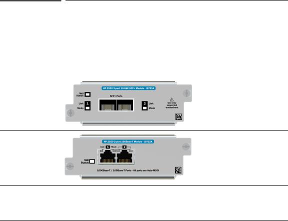
■A 2-port 10-GbE SFP+ module. This module provides two bays for SFP+ transceivers.
■A 2-port 10GBASE-T module. This module provides two 10GBASE-T RJ-45 connectors.
Stacking Module slot
Each of the HP 2920 switches has one slot that can accept the HP 2920 Stacking Module that provides high-speed connectivity to other HP 2920 switches. Only the HP 2920 switches support this module. See “HP 2920 Stacking Module” on page 1-18 for more information.
|
HP 2920 10G Expansion Modules |
|
The HP 2920 10G Expansion Modules are components you can add to a HP |
|
2920 Switch to provide a variety of network connectivity options. The |
|
following modules are available: |
|
|
Module |
Description |
|
|
HP 2920 2-Port 10-GbE |
2-port 10 Gigabit switch expansion |
SFP+ Module (J9731A) |
module. This module has two slots |
|
for HP SFP+ transceivers. |
HP 2920 2-Port 10GBASE-T Module (J9732A)
2-port 10 Gigabit switch expansion module. This module has two 10GBASE-T RJ-45 ports.
1-15
Introducing the HP 2920 Switches
HP 2920 10G Expansion Modules
Contact your HP Networking authorized networking products reseller or your HP Networking representative for information on availability of other modules and transceivers. You can also visit the HP Networking products website www.hp.com/networking/support to get more information.
10G Expansion Module features
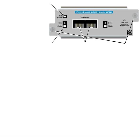
Figure 1-8. Example HP 2920 10G Expansion Module
HP 2920 10-GbE SFP+ Module
|
|
|
|
|
|
|
|
|
|||
|
|
|
|
|
|
|
|
|
|
||
|
|
|
|
|
|
|
|
|
|
|
|
|
Module Status LEDs |
|
SFP/SFP+ transceiver bays |
|
|
|
|
|
Link and Mode LEDs (one pair per port) |
|
Retaining screws |
|
|
|
|
The HP 2920 10G Expansion Modules have the following features:
■Connectivity ports: two 10GBASE-T RJ-45 ports, or two SFP+ bays, depending on the module installed.
■LEDs that provide information on the module status, and the link status and LED mode for each port.
■“hot swap transceiver” support—you can add, replace, or change the type of any of the transceivers that you use in the SFP+ module ports, without having to first remove the module, and without having to shut down the switch.
Standards adherence:
■10G BASE-T Module: IEEE 802.3an-2006 Type 10GBASE-T
■10-GbE SFP+ Module: See “Connectivity standards” on page A-3
1-16

Introducing the HP 2920 Switches
HP 2920 10G Expansion Modules
N o t e |
The HP 2920 10G Expansion Modules are not “Hot-swappable”. |
10G Expansion Module LEDs
The following LEDs are located on the bulkheads of the HP 2920 10G Modules. These LEDs are only viewable in the rear of the switch on the module itself.
Table 1-5. |
10G Expansion Modules LEDs |
||
|
|
|
|
Name |
|
Mode |
Description |
|
|
|
|
LEDs per module |
|
||
|
|
|
|
Module |
|
On |
Stacking module is installed into the module slot and is |
Status |
|
|
operating correctly. |
(green/ |
|
|
|
orange) |
|
|
|
(Replicated |
|
Off |
Stacking module is not installed into the module slot. |
|
|
|
|
on the |
|
Blink |
• If the LED is blinking simultaneously with the switch Fault |
switch front |
|
||
|
orange |
LED, then the Stacking Module is installed into the module |
|
as the Mdl |
|
||
|
|
slot but has experienced a fault. |
|
LED.) |
|
|
|
|
|
• If the LED is blinking without the switch Fault LED, a stack- |
|
|
|
|
|
|
|
|
ing cable is not connected correctly at its other end, or it |
|
|
|
is connected to a switch that is powered off. |
|
|
|
The module was installed while the switch was powered on. |
|
|
Fast blink |
The module was installed while the switch was powered on. |
|
|
orange |
The switch must be rebooted to support the module. |
|
|
|
|
LEDs per port |
|
||
|
|
|
|
Link |
|
On |
The port is enabled and receiving a link indication from the |
(green/ |
|
|
connected switch. |
orange) |
|
|
|
|
|
Off |
The port has no active stacking cable connected, is not |
|
|
|
receiving the link indication, or the port may have been |
|
|
|
disabled through the switch console, the web browser |
|
|
|
interface, or network management interface. |
|
|
Blinking |
• If the LED is blinking simultaneously with the switch Fault |
|
|
orange |
LED, the corresponding port has failed its self test. The |
|
|
|
module status LEDs (on the module and front of the switch |
|
|
|
will also be blinking). |
|
|
|
• If the LED is blinking without the switch Fault LED, then the |
|
|
|
switch detects the stacking cable but the cable is not |
|
|
|
getting is not connected correctly at the other switch, or |
|
|
|
the cable may be faulty, or there is |
|
|
|
|
1-17
Introducing the HP 2920 Switches
HP 2920 Stacking Module
Name |
Mode |
Description |
|
|
|
Mode |
Same as the per-port Mode LEDs on the front of the switch. See Table 1-3 |
|
(green) |
on page 1-7 for a description. |
|
|
|
|
|
|
|
HP 2920 Stacking Module
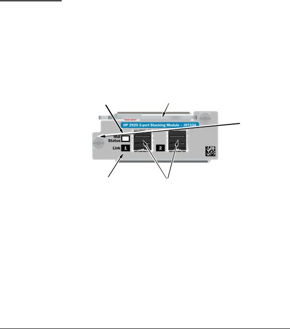
The HP 2920 2-port Stacking Module (J9733A) is a component you can add to an HP 2920 Switch to provide high-speed stacking connections to other HP 2920 switches. See “Stacking information and topologies” on page 2-27, and the HP 2920 Advanced Traffic Management Guide for more information about stacking configuration and operation.
Figure 1-9. Front of HP 2920 2-Port Stacking Module


|
|
|
|
|
|
|
|
|
|||
|
|
|
|||
|
Module Status LED |
|
Stacking connectors |
||
|
|
|
|
||
|
Extractor handle |
|
Link LEDs (one per port) |
||
|
|
|
|
|
|
|
Retaining screws |
|
|
|
|
|
|
|
|
|
|
Stacking Module features
The HP 2920 2-Port Stacking Module J9733A has the following features:
■Two stacking connectors for connecting the HP 2920 switch to other HP 2920s in a stacked topology (chain or ring). Any of these available HP 2920 stacking cables can be used for these connections:
1-18

Introducing the HP 2920 Switches
HP 2920 Stacking Module
•0.5m Stacking Cable (J9734A)
•1.0m Stacking Cable (J9735A)
•3.0m Stacking Cable (J9736A)
■LEDs, described in Table 1-6.
Stacking Module LEDs
The following LEDs are located on the HP 2920 Stacking Module bulkhead. These LEDs are only viewable in the rear of the switch on the module itself.
Table 1-6. |
Stacking Module LEDs |
||
|
|
|
|
Name |
|
Mode |
Description |
|
|
|
|
Stacking LEDs per module |
|
||
|
|
|
|
Module |
|
On |
Stacking module is installed into the module slot and is |
Status |
|
|
operating correctly. |
(green/ |
|
|
|
orange) |
|
Off |
Stacking module is not installed into the module slot. |
|
|
||
(Replicated |
|
Blink |
• If the LED is blinking simultaneously with the switch Fault |
on the |
|
||
|
orange |
LED, then the Stacking Module is installed into the module |
|
switch front |
|
||
|
|
slot but has experienced a fault. |
|
as the Mdl |
|
|
|
|
|
• If the LED is blinking without the switch Fault LED, a stack- |
|
LED.) |
|
|
|
|
|
|
ing cable is not connected correctly at its other end, or it |
|
|
|
is connected to a switch that is powered off. |
|
|
|
The module was installed while the switch was powered on. |
|
|
Fast blink |
The module was installed while the switch was powered on. |
|
|
orange |
The switch must be rebooted to support the module. |
|
|
|
|
Stacking Module LEDs per port |
|||
|
|
|
|
1-19

Introducing the HP 2920 Switches
HP 2920 Stacking Module
Name |
Mode |
Description |
|
|
|
Link |
On |
The port is enabled and receiving a link indication from the |
(green/ |
|
connected switch. |
orange) |
|
|
|
Off |
The port has no active stacking cable connected, is not |
|
|
receiving the link indication, or the port may have been |
|
|
disabled through the switch console, the web browser |
|
|
interface, or network management interface. |
|
Blinking |
• If the LED is blinking simultaneously with the switch Fault |
|
orange |
LED, the corresponding port has failed its self test. The |
|
|
module status LEDs (on the module and front of the switch |
|
|
will also be blinking). |
|
|
• If the LED is blinking without the switch Fault LED, then the |
|
|
switch detects the stacking cable but the cable is not |
|
|
getting is not connected correctly at the other switch, or |
|
|
the cable may be faulty, or there is |
|
|
|
1-20

Introducing the HP 2920 Switches
HP 2920 Switch features
HP 2920 Switch features
The features of the HP 2920 Switches include:
■Network ports as described under “Network ports” on page 1-4:
•20 or 44 auto-sensing 10/100/1000BASE-T with Auto-MDIX.
•Four dual-personality ports – either the auto-sensing 10/100/ 1000BASE-T RJ-45 or the SFP slot can be used for each port.
■One module slot is provided in the back of the switches to support a stacking module to provide connectivity to other HP 2920 switches with stacking modules. See “Stacking information and topologies” on page 2- 27, the HP 2920 Advanced Traffic Management Guide for more information about stacking.
■Two 10G Expansion Module slots to provide additional high-speed network connectivity and a variety of network connectivity options.
■Power over Ethernet (PoE/PoE+) operation for all RJ-45 ports on the fronts of the HP 2920-24G-PoE+ and HP 2920-48G-PoE+ Switches. These switches are IEEE 802.3at standard compliant and provide up to 30 W per RJ-45 port to power IP phones, wireless access points, web cameras, and other PoE/PoE+ PDs. For more information, see the HP Power over Ethernet (PoE/PoE+) Planning and Implementation Guide which is on the HP Web site, www.hp.com/networking/support.
The switches support 802.3af and 802.3at standard devices and some prestandard PoE devices. For a list of these devices, see the FAQs (Frequently Asked Questions) for your switch model. PoE is disabled by default and must be enable for use. (For instructions, see the Management and Configuration Guide for your switch at www.hp.com/networking/support.
■A replaceable internal power supply.
■Connection to an HP 640 RPS/EPS Shelf which can hold up to three HP X331 and X332 power supplies (the same ones that you install in your 2920 switch). These external power supplies provide additional power to the switch for power redundancy, and for additional PoE/PoE+ power for the 2920-PoE+ switches. For more information, see the HP 640 RPS/EPS Shelf Installation and Power Setup Guide.
■Plug-and-play networking—all ports are enabled—just connect the network cables to active network devices and your switched network is operational.
■An auxiliary port (USB Type A connector) for processing a USB command file and updating switch software.
1-21

Introducing the HP 2920 Switches
HP 2920 Switch features
■Auto MDI/MDI-X on all twisted-pair ports (10/100/1000BASE-T on the switch front, and 10GBASE-T – available on the optional 10G module), meaning that all connections can be made using straight-through twisted-pair cables. Cross-over cables are not required, although they will also work. (See the appendices for recommended or required cabling.)
■Automatic learning of the network addresses in each switch’s 16,000address forwarding table, (with configurable address aging value).
■Automatically negotiated full-duplex operation for the 10/100/1000 RJ-45 ports when connected to other auto-negotiating devices—the SFP/SFP+ ports (available on an optional 10G module) always operate at full duplex.
■Easy management of the switch through several available interfaces:
•Console interface—a full featured, easy to use, VT-100 terminal interface for out-of-band switch management (through the console port or Management network ports) or in-band Telnet access to the switch.
•Web browser interface—an easy to use built-in graphical interface that can be accessed from common web browsers.
•HP Intelligent Management Center (IMC)—an SNMP-based, graphical network management tool that you can use to manage your entire network.
■Support for the Spanning Tree Protocol (RSTP) and Rapid Per VLAN Spanning Tree Plus (RPVST+) to eliminate network loops.
■Support for OpenFlow communication protocol enables sophisticated traffic management compared to access control lists (ACLs) and routing protocols.
■Support for CDPv2 provides more intelligent device tracking features.
■Support for up to 256 IEEE 802.1Q-compliant VLANs so you can divide the attached end nodes into logical groupings that fit your business needs.
■Support for many advanced features to enhance network performance— for a description, see the HP 2920 Management and Configuration Guide at www.hp.com/networking/support.
■Ability to update the switch software. Software updates are routinely available from HP.
■Low power operation:
•Ports on a switch or stack member may be set to operate at reduced power.
•Port status LEDs may be turned off.
RJ-45 ports will operate at reduced power if the port is not connected (link partner is not detected).
1-22
Loading...