


 Loading...
Automatic Test and Calibration Station
Quick Reference Guide
Limited Warranty and Limitation Liability
BW Technologies LP (BW) warrants the product to be free from defects in material and workmanship under normal use and service for a period of two years, beginning on the date of shipment to the buyer. This warranty extends only to the sale of new and unused products to the original buyer. BW’s warranty obligation is limited, at BW’s option, to refund of the purchase price, repair or replacement of a defective product that is returned to a BW authorized service center within the warranty period. In no event shall BW’s liability hereunder exceed the purchase price actually paid by the buyer for the Product.
This warranty does not include:
a)fuses, disposable batteries or the routine replacement of parts due to the normal wear and teat of the product arising from use;
b)any product which in BW’s opinion, has been misused, altered, neglected or damaged, by accident or abnormal conditions of operation, handling or use;
c)any damage or defects attributable to repair of the product by any person other than an authorized dealer, or the installation of unapproved parts on the product; or
The obligations set forth in this warranty are conditional on:
a)property storage, installation, calibration, use, maintenance and compliance with the product manual instructions and any other applicable recommendations of BW;
b)the buyer promptly notifying BW of any defect and, if required, promptly making the product available for correction. No goods shall be returned to BW until receipt by the buyer of shipping instructions from BW; and
c)the right of BW to require that the buyer provide proof of purchase such as the original invoice, bill of sale or packing slip to establish that the
product is within the warranty period.
THE BUYER AGREES THAT THIS WARRANTY IS THE BUYER’S SOLE AND EXCLUSIVE REMEDY AND IS IN LIEU OF ALL OTHER WARRANTIES, EXPRESS OR IMPLIED, INCLUDING BUT NOT LIMITED TO ANY IMPLIED WARRANTY OF MERCHANTABILITY OR FITNESS FOR A PARTICULAR PURPOSE. BW SHALL NOT BE LIABLE FOR ANY
SPECIAL, INDIRECT, INCIDENTAL, OR BASED ON CONTRACT, TORT OR RELIANCE OR ANY OTHER THEORY.
Since some countries or states do not allow limitation of the term of an implied warranty, or exclusion or limitation of incidental or consequential damages, the limitations and exclusions of this warranty may not apply to every buyer. If any provision of this warranty is held invalid or unenforceable by a court of competent jurisdiction, such holding will not affect the validity or enforceability of any other provision.
Contacting BW Technologies by Honeywell
USA: 188-749-8878 |
Canada: 1-800-663-4164 |
Europe: +44(0) 1295 700300 |
Other countries: +1-403-248-9226 |
Email us at: info@gasmonitors.com
Visit BW Technologies by Honeywell website at: www.gasmonitors.com

Introduction
a Warning
To ensure personal safety, read Safety Information - Read First before using the MicroDock II base station.
The MicroDock II Automatic Test and Calibration Station (“the base station”) provides automated calibration and bump testing for the GasAlert Extreme, GasAlertClip Extreme, GasAlertMicro, GasAlertMicro 5/PID/IR, GasAlertMicroClip, and GasAlertMax XT detectors. The system is expandable to include up to 10 docking modules (maximum six charging docking modules plus four non-charging docking modules.
Safety Information - Read First
Use the station only as specified in this guide. Read the following Cautions before using the station.
aCautions
•If the base station is damaged or parts are missing, contact BW Technologies by Honeywell immediately.
•This equipment uses potentially harmful gas for calibration. Use in a well-ventilated area only.
MicroDock II
aCautions
•The base station must be attached to a venting system or the base station must be used in a well-ventilated area.
•Do not immerse the station in liquids.
•The maximum recommended exhaust line length is
15.24m (50 ft.).
•Ensure that the inlet filter is clean.
•Ensure that all gas cylinders contain enough gas.
•A demand flow regulator must be used with all gas cylinder connections.
•Calibrate and bump test only in a safe area that is free of hazardous gas.
•Do not expose the station to electrical shock or severe continuous mechanical shock.
•The base station warranty will be void if the unit is disassembled, adjusted, or serviced by non-BW Technologies by Honeywell personnel.
•Ensure the exhaust line is not connected to a negative pressure system.
1

MicroDock II
Quick Reference Guide
Display Elements
Item |
Function |
|
|
|
AC power |
|
|
|
Batteries fully charged |
|
|
|
Batteries half-charged |
|
|
|
Batteries at low level |
|
|
|
MultiMediaCard (MMC) |
|
|
|
MultiMediaCard (MMC) not inserted |
|
|
|
Test pass and option enabled |
|
|
|
Test fail and option disabled |
|
|
|
Cursor and sensor disabled |
|
Scroll up |
|
Scroll down |
|
|
|
Selection arrow |
|
|
|
Selected to be modified |
|
|
|
Passcode protected |
|
|
Pushbuttons
Pushbutton |
Description |
|
|
|
|
|
To bump test a detector, press C |
|
C |
BUMP CHECK. |
|
When connecting a new docking |
||
BUMP CHECK |
module, press and hold |
|
C BUMP CHECK to send a |
||
|
confirmation signal back to the |
|
|
base station. |
|
|
|
|
C |
To calibrate a detector, press |
|
C CALIBRATION (all models |
||
CALIBRATION |
||
excluding GasAlertClip Extreme). |
||
|
|
|
|
To transfer datalog information |
|
|
from a detector, press C DATA |
|
|
TRANSFER. (GasAlert |
|
|
Extreme, GasAlertMicroClip, and |
|
|
GasAlertMax XT only). |
|
C |
The Automatic Datalog Down- |
|
DATA TRANSFER |
load option is available for the |
|
GasAlertMicroClip and GasAlert- |
||
|
||
|
Max XT docking modules only. |
|
|
For more information, refer to |
|
|
Data Transfer (GasAlert |
|
|
Extreme, GasAlertMicroClip, |
|
|
GasAlertMax XT only). |
|
|
|
2
MicroDock II
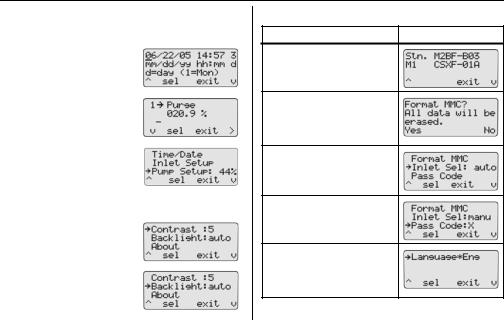
User Options Menu
User Options Menu
Description |
Display |
|
|
Time/Date modifies the time and |
|
date of the base station. |
|
|
|
Inlet Setup enters the gas type, |
|
the gas concentration levels, and |
|
the gas cylinder lot numbers. |
|
|
|
Pump Setup modifies the station |
|
pump speed. Recommended |
|
pump speeds are 40-45% (350 |
|
ml/min.). The pump speed must |
|
be set for each new docking mod- |
|
ule that is added to the station. |
|
NOTE: A flow meter is required. |
|
|
|
Contrast brightens or dims the |
|
text of the LCD. |
|
|
|
Backlight enables/disables the |
|
LCD backlight. When enabled, |
|
the auto option automatically |
|
deactivates the backlight when |
|
the base station is not in use. |
|
|
|
Description |
Display |
About displays the firmware revision for the base station and the docking module(s).
Format MMC formats the MultiMediaCard (MMC). NOTE: This feature erases all current data. Refer to the MicroDock II User Manual.
Inlet Sel selects a gas inlet. If auto is displayed, the base station automatically selects the correct inlet for the test.
Pass Code prevents unauthorized access to the menu
options. The LCD displays  when it is pass code protected.
Language displays all LCD text in one of five languages: Eng (English), Fran (French), Deut (German), Port (Portuguese), and Espa (Spanish).
3
MicroDock II
Quick Reference Guide
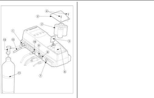
Installation
Item |
Description |
|
|
1 |
Inlet filter assembly |
|
|
2 |
C-cell batteries (4) |
|
|
3 |
Battery cover |
|
|
4 |
Philips pan head retaining screws (2) |
|
|
5 |
MultiMediaCard (MMC) |
|
|
6 |
Battery compartment |
|
|
7 |
Charger port |
|
|
8 |
USB port |
|
|
9 |
Power port |
|
|
10 |
Exhaust outlet |
|
|
11 |
Gas cylinder |
|
|
12 |
Demand flow regulator |
|
|
13 |
Calibration gas hose |
|
|
4
Loading...