


Honda CRF450R |
|
OWNER’S MANUAL |
2004 |
All information in this publication is based on the latest product information available at the time of approval for printing. Honda Motor Co., Ltd. reserves the right to make changes at any time without notice and without incurring any obligation.
No part of this publication may be reproduced without written permission.
© Honda Motor Co., Ltd. 2003
TO THE NEW OWNER
By selecting a Honda motocross CRF450R as your new motorcycle, you have placed yourself in a distinguished family of motorcycle owners and riders.
 WARNING
•The CRF is a high performance racing motorcycle utilizing the latest motocross technology. This motorcycle is intended for competition use by experienced riders only.
This new motocross model was desighed to be as competitive as possible. But motocross is a physically demanding sport that requires more than just a fine motorcycle.To do well, you must be in excellent physical condition and be a skillful rider. For the best possible results, work diligently on your physical conditioning and practice frequently.
The purpose of this Owner’s Manual is to help ensure that you obtain the greatest possible satisfaction from your new CRF motocrosser – satisfaction with the performance of the motorcycle, and through success in competition.
The Service Manual for your CRF is available from your authorized Honda dealer. It is the same manual your dealer uses. If you plan to do any service on your CRF beyond the standard maintenance procedures included in this Owner’s Manual, you will find the Service Manual an effective and worthwhile tool. If your dealer does not have the Service Manual for your particular year and model in stock, he can order it.
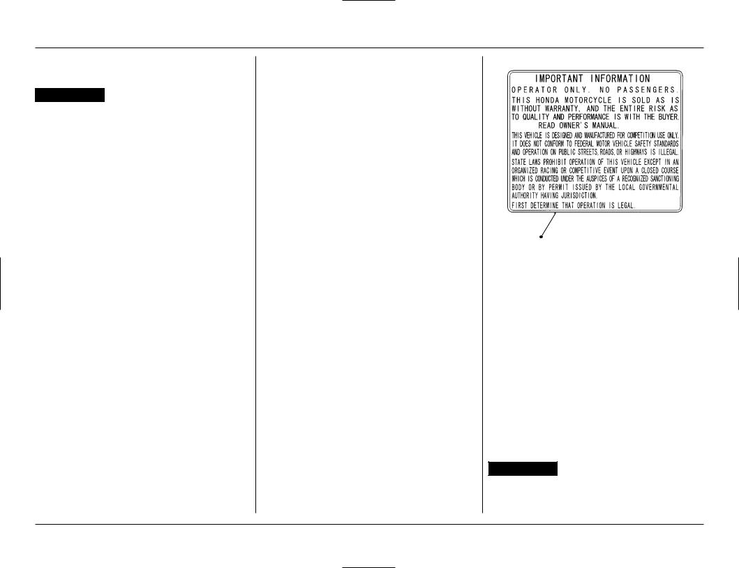
Read this WARNING LABEL before you ride.
PROTECTIVE APPAREL
1.Most motorcycle accident fatalities are due to head injuries: ALWAYS wear an approved motorcycle helmet. You should also wear a face shield or goggles, boots, gloves, and protective clothing.
2.The exhaust system becomes very hot during operation, and it remains hot after operation. Never touch any part of the hot exhaust system. Wear clothing that fully covers your legs.
3.Do not wear loose clothing which could catch on the control levers, kickstarter, footpegs, drive chain, or wheels.
MODIFICATIONS
 WARNING
•Modification of the motorcycle, or removal of original equipment may render the vehicle unsafe or illegal. Obey all federal, state, and local equipment regulations.
3

CONTENTS
1. OPERATING INSTRUCTIONS ............................ |
2 |
Fuel .................................................................. |
2 |
Basic Operation .............................................. |
2 |
• Starting The Engine ................................ |
2 |
• Stopping The Engine .............................. |
3 |
• Break-In Procedure ................................. |
3 |
Contotls ........................................................... |
4 |
Control Adjustment ....................................... |
5 |
• Clutch Lever Free Play ............................ |
5 |
• Clutch Lever Position .............................. |
5 |
• Hot Start .................................................. |
6 |
• Throttle Grip ............................................ |
6 |
• Front Brake Lever .................................... |
7 |
• Brake Pedal Height ................................. |
7 |
Adjustment For Personal Fit ......................... |
8 |
• Control Positioning ................................. |
8 |
• Handlebar Position, Width & Shape ..... |
8 |
• Additional Individualized |
|
Adjustments ............................................ |
8 |
2. SPECIFICATIONS ................................................ |
9 |
3. OPTIONAL PARTS .............................................. |
10 |
Optional Parts List .......................................... |
10 |
4. SERVICE AND MAINTENANCE ......................... |
11 |
Pre-ride Inspection Check List ....................... |
11 |
Maintenance Schedule .................................. |
11 |
General Service Information ......................... |
12 |
Between Moto/Between Practice And Moto |
|
Maintenance ................................................... |
12 |
After Race Maintenance ................................ |
13 |
• After Race Lubrication ............................ |
13 |
• Routine Cleaning .................................... |
13 |
• Pressurized Spray Washers ................... |
13 |
• Condensation Control ............................ |
13 |
• After Cleaning Lubrication ..................... |
13 |
General Maintenance .................................... |
14 |
Maintenance Preparations ............................ |
17 |
• Seat .......................................................... |
17 |
• Fuel Tank .................................................. |
17 |
• Subframe ................................................. |
19 |
Maintenance Procedures ............................... |
21 |
• Engine Oil ................................................ |
21 |
• Transmission Oil ..................................... |
23 |
• Coolant .................................................... |
24 |
• Spark Plug ............................................... |
25 |
• Ignition ..................................................... |
26 |
• Engine Idle Speed ................................... |
26 |
• |
.................................Crankcase Breather |
27 |
............................................................14. STORAGE |
101 |
• |
Air Cleaner ............................................... |
27 |
• To Prepare The Motorcycle For |
|
• |
Clutch ....................................................... |
28 |
Storage .................................................... |
101 |
• |
Valve ........................................................ |
30 |
• Removal From Storage .......................... |
101 |
• |
Piston/Piston Rings/Piston Pin ............... |
39 |
15. WIRING DIAGRAM ............................................. |
102 |
• |
Handlebar And Steering Head |
|
16. INDEX .................................................................. |
103 |
• |
Bearings .................................................. |
47 |
17. AUTHORIZED MANUALS .................................. |
105 |
Throttle Grip ............................................ |
47 |
|
|
|
• |
Fuel Line .................................................. |
48 |
|
|
• |
Front And Rear Wheels And Tires ......... |
49 |
|
|
• |
Front Suspension .................................... |
49 |
|
|
• |
Rear Suspension ..................................... |
50 |
|
|
• |
Brakes ...................................................... |
51 |
|
|
• |
Drive Chain .............................................. |
52 |
|
|
• |
Drive Chain Sliders ................................. |
54 |
|
|
• |
Drive Chain Rollers ................................. |
54 |
|
|
• |
Driven Sprocket ...................................... |
55 |
|
|
• |
Exhaust Pipe/Muffler .............................. |
55 |
|
|
• |
Control Cables ......................................... |
57 |
|
|
• |
Nuts, Bolts, Fasterers ............................. |
58 |
|
|
5. CARBURETOR ADJUSTMENT .......................... |
61 |
|
|
|
• |
Carburetor ............................................... |
61 |
|
|
• |
Tuning For Special Conditions ............... |
70 |
|
|
• |
Spark Plug Coloring Indications ............ |
70 |
|
|
6. SUSPENTION ADJUSTMENT ........................... |
71 |
|
|
|
• |
Race Sag .................................................. |
71 |
|
|
• |
Rear Suspension ..................................... |
72 |
|
|
• |
Front Suspension .................................... |
74 |
|
|
• |
Suspension Adjustments Relating To |
|
|
|
• |
Specific Track Conditions ....................... |
90 |
|
|
Suspension Adjustment Guidelines ...... |
91 |
|
|
|
7. CHASSIS ADJUSTMENTS FOR TRACK |
|
|
|
|
CONDITIONS ...................................................... |
94 |
|
|
|
• |
Rear End .................................................. |
94 |
|
|
• |
Fork Height/Angle ................................... |
94 |
|
|
• |
Wheelbase ............................................... |
94 |
|
|
8. GEARING SELECTION ....................................... |
94 |
|
|
|
9. TIRE SELECTION ................................................ |
95 |
|
|
|
10. MAINTENANCE, TUNING & RACING |
|
|
|
|
LOGBOOK ........................................................... |
96 |
|
|
|
11. SPARE PARTS & EQUIPMENT ........................... |
98 |
|
|
|
12. TROUBLESHOOTING ......................................... |
99 |
|
|
|
• |
Poor Performance At Low And |
|
|
|
• |
Unstable Idle Speeds ............................. |
99 |
|
|
Poor Performance At High Speed ......... |
99 |
|
|
|
13. CLEANING ........................................................... |
100 |
|
|
|
|
|
|
|
|
1

1.OPERATING INSTRUCTIONS
FUEL
Fuel tank capacity: 2.0 US gal (7.4 liter, 1.6 lmp gal)
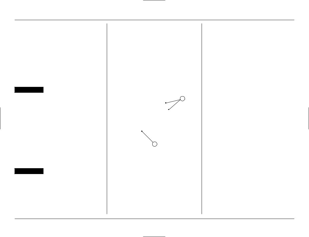
To open the fuel fill cap, pull the breather tube out of the steering stem nut. Then turn the fuel fill cap counterclockwise.
•Use automobile gasoline with a pump octane number of 92 or higher. If “knocking” or “pinging” occurs, try a different brand of gasoline or a higher octane grade.
 WARNING
•Gasoline is extremely flammable and is explosive under certain conditions. Perform this operation in a well-ventilated area with the engine stopped. Do not smoke or allow flames or sparks in the area where gasoline is drained or stored and where the fuel tank is refueled.
(1) FUEL FILL CAP |
(2) BREATHER TUBE |
BASIC OPERATION
Starting The Engine
 WARNING
•Never run the engine in an enclosed area. The exhaust contains poisonous carbon monoxide gas that can cause loss of consciousness and lead to death.
•Attempting to start the engine with the transmission in gear and clutch engaged may result in injury or damage.
NOTE:
•This motorcycle can be kickstarted with the transmission in gear by disengaging the clutch before operating the kickstarter.
Check the engine oil, transmission oil and coolant levels before starting the engine (page 21, 23, 24).
Cold Engine Starting:
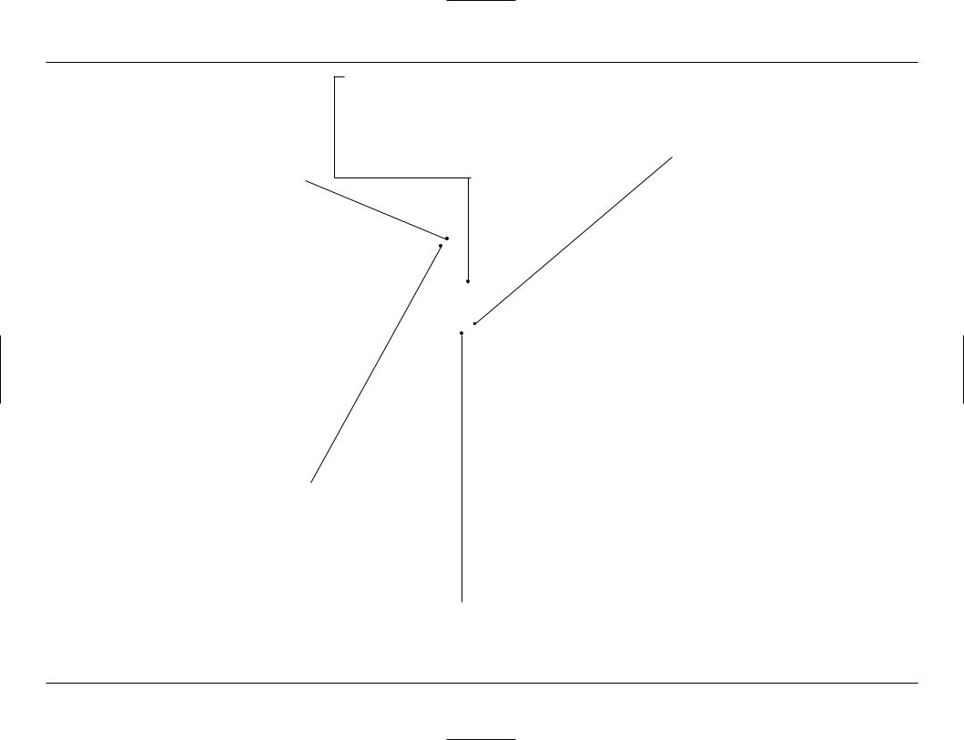
1.Turn the fuel valve ON.
2.Shift the transmission into neutral.
3.If the temperature is 35°C (95°F) or below, pull the choke knob fully out.
4.If the temperature is below 0°C (32°F), open the throttle two or three times. (The engine requires a richer mixture for starting in cold weather. When the throttle is so opened, the accelerator pump will feed extra fuel to the cylinder, thereby facilitating starting in cold weather.)
5.With the throttle closed, operate the kickstarter starting from the top of the kickstarter stroke, kick through to the bottom with a rapid, continuous motion.
(Do not open the throttle, As the carburetor is equipped with an accelerator pump, excessive fuel will be charged into the engine, and the spark plug will be fouled if the throttle is opened and closed repeatedly. Excessive fuel in the engine makes kickstarting difficult.)
6.About a minute after the engine starts, push the choke knob back all the way to fully OFF.
If idling is unstable, open the throttle slightly.
ON |
OFF |
(1) FUEL VALVE |
(2) CHOKE KNOB |
Warm Engine Starting:
1.Turn the fuel valve ON.
2.Shift the transmission into neutral.
3.Pull the hot start lever and kick-start the engine. (Do not open the throttle.)
4.As soon as the engine starts, release the hot start
1
(1) HOT START LEVER
2
Starting the engine after a stall during riding or after a fall:
1.Shift the transmission into neutral.
2.Pull the hot start lever and kick-start the engine. (Do not open the throttle.)
3.As soon as the engine starts, release the hot start lever.
Starting the engine excessively charged with fuel by throttle blipping or other reasons:
1.Shift the transmission into neutral.
2.With the throttle fully opened, repeat kickstarter operation approximately 10 times very slowly to discharge excessive fuel from the engine.
3.Pull the hot start lever and kick-start the engine (Do not open the throttle.)
4.As soon as the engine starts, release the hot start lever.
Stopping The Engine
1.Shift the transmission into neutral.
2.Turn the fuel valve OFF.
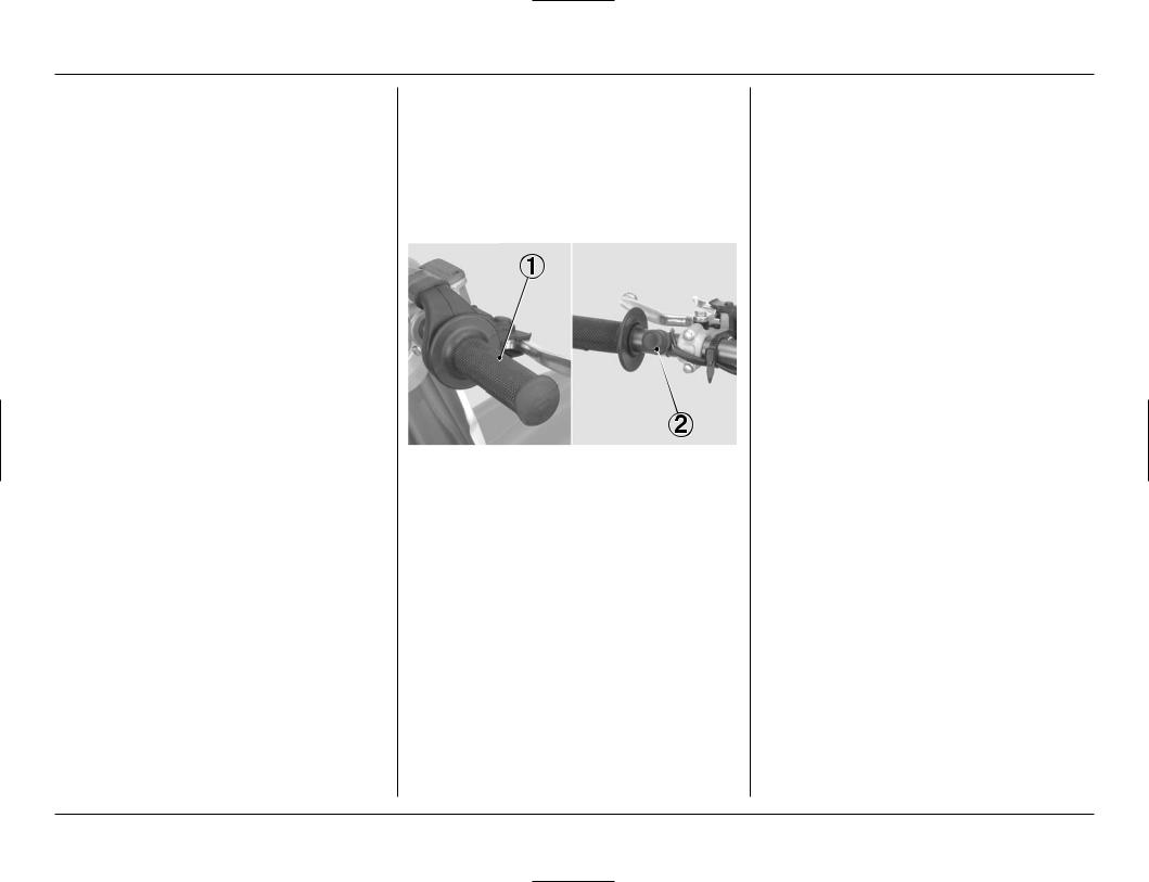
3.Lightly open the throttle 2 – 3 times, and then close it.
4.Depress and hold the engine stop button until the engine stops completely.
NOTE:
•Failure to close the fuel valve may cause the carburetor to overflow.
(1) THROTTLE GRIP |
(2) ENGINE STOP BUTTON |
Break-In Procedure
Help assure your CRF’s future reliability and performance by paying extra attention to how you ride during the first operating day or 15 miles (25 km).
During this period, avoid full-throttle starts and rapid acceleration.
This same procedure should be followed each time when:
•Piston is replaced
•Rings are replaced
•Cylinder is replaced
•Crankshaft or crank bearing are replaced
3
1.OPERATING INSTRUCTIONS
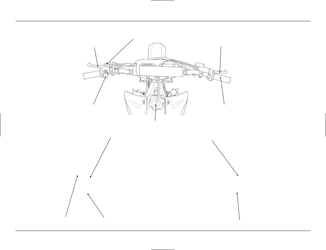
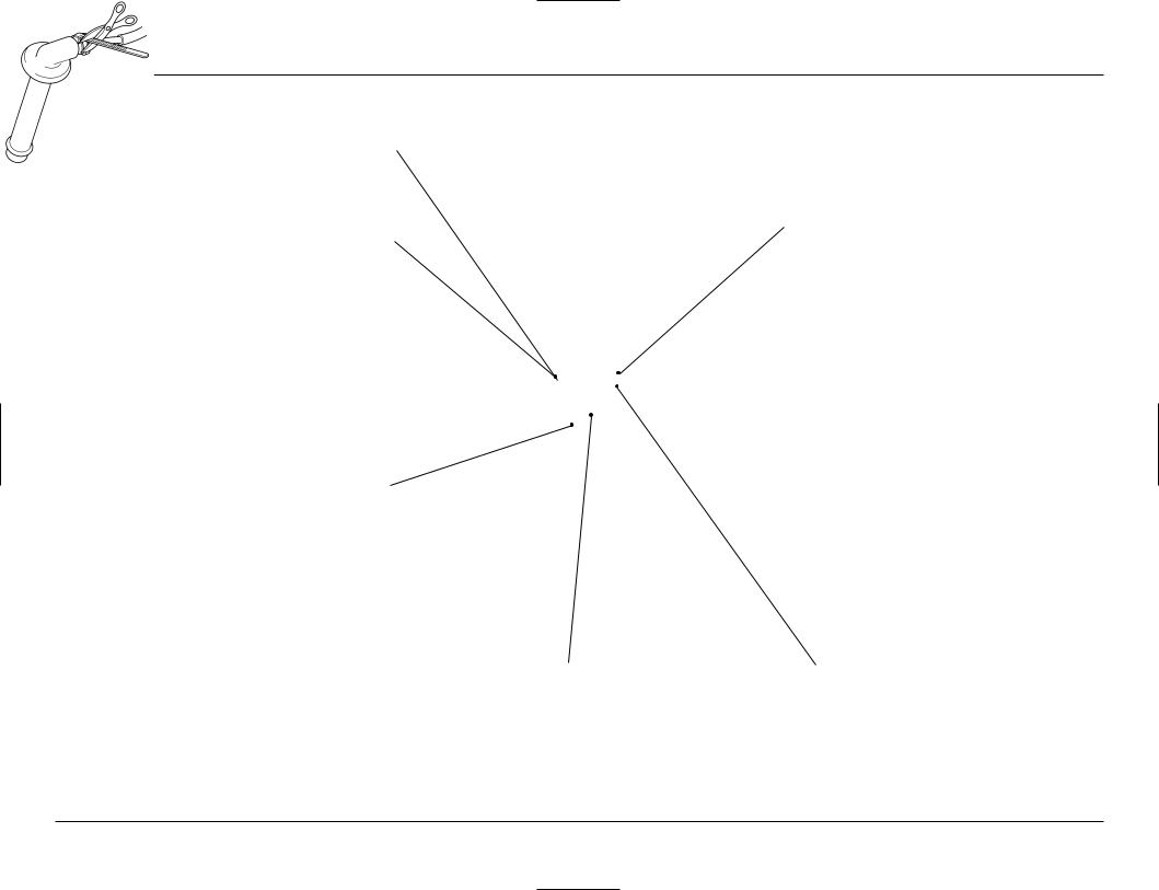
CONTROLS
HOT START LEVER
CLUTCH LEVER |
FRONT BRAKE LEVER |
ENGINE STOP BUTTON |
THROTTLE GRIP |
FUEL FILL CAP
CHOKE KNOB
KICKSTARTER
FUEL VALVE |
SHIFT LEVER |
REAR BRAKE PEDAL
4

CONTROL ADJUSTMENT
Clutch Lever Position
CAUTION:
•Make sure to adjust the clutch lever free play after the clutch lever position adjustment or clutch cable disconnected.
1.The clutch lever position can be adjusted by looseing the lock nut and turning the adjuster.
Turning the adjuster counterclockwise moves the clutch lever farther away from the grip; turning the adjuster clockwise moves the clutch lever closer to
2
1
(1) ADJUSTER |
(2) LOCK NUT |
2.Turn the cable end adjuster in direction A until it seats lightly and then turn it out 5 turns.
B
A
1
(1) CABLE END ADJUSTER
(A)INCREASE
(B)DECREASE
3.
2
D
1C
(1)LOCK NUT
(2)INTEGRAL CABLE ADJUSTER
(C) INCREASE
(D) DECREASE
4. Adjust the cable end adjuster for minor adjustment.
F
E
1
(1) CABLE END ADJUSTER
(E)INCREASE
(F)DECREASE
Clutch Lever Free Play
1.The normal clutch lever free play is 3/8 – 3/4 in (10 – 20 mm) at the tip of the lever.
1
2
(1) CLUTCH LEVER |
(2) DUST COVER |
2.Minor adjustments can be made with the cable end adjuster.
Turning the adjuster in direction A will increase free play and turning it in direction B will decrease free play.
If the adjuster is threaded out near its limit or the correct free play cannot be reached, turn the adjuster all the way in and back out one turn and make the adjustment with the integral cable adjuster.
5
1. OPERATING INSTRUCTIONS
B
A
1
(1) CABLE END ADJUSTER
(A) INCREASE (B) DECREASE
3.Major adjustments can be made at the integral cable adjuster.
Loosen the lock nut and turn the adjuster. Turning the adjuster in direction C will increase free play and turning it in direction D will decrease free play. Tighten the lock nut after adjusting.
4.Test ride to be sure the clutch operates properly without slipping or dragging.
NOTE :
• If proper adjustment still cannot be obtained or the clutch does not operate correctly, see pages 28 – 30, refer to the Honda Service Manual, or see your authorized Honda dealer for clutch disassembly and wear inspection.
|
|
2 |
|
D |
|
1 |
C |
|
(1) LOCK NUT |
(2) INTEGRAL CABLE ADJUSTER |
|
(C) INCREASE |
(D) DECREASE |
|
Hot Start
1.The normal hot start lever free play is 1/16 – 1/8 in (2 – 3 mm) at the tip of the lever.
21
(1)HOT START LEVER
(2)DUST COVER
2.Adjustments can be made with the cable end adjuster.
Loosen the lock nut and turn the adjuster Turning the adjuster in direction A will increase free play and turning in direction B will decrease free play. After adjustment, tighten the lock nut.
1
A
2 |
B |
|
|
(1) LOCK NUT |
(2) CABLE ADJUSTER |
(A) INCREASE |
(B) DECREASE |
Throttle Grip
Standard throttle grip free play is approximately 1/8 – 3/16 in (3 – 5 mm) of grip rotation.
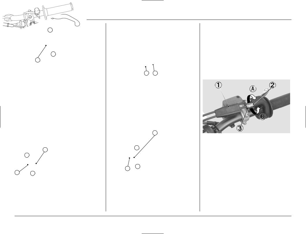
1.Minor adjustment is made with the upper adjuster. Remove the dust cover and loosen the lock nut. Turning the adjuster in direction A will increase free play and turning it in direction B will decrease free play. Tighten the lock nut and reinstall the dust cover after adjustment.
If the adjuster is threaded out near its limit or the correct free play cannot be reached, turn the adjuster all the way in and back out one turn.
Tighten the lock nut, install the dust cover and make the adjustment with the carburetor top adjuster.
(1) |
DUST COVER |
(2) LOCK NUT |
(3) |
UPPER ADJUSTER |
(A) INCREASE (B) DECREASE |
6
2.Remove the fuel tank (page 17).
3.To make major adjustments, loosen the lock nut. Turn the adjuster in direction C to increase free play, and in direction D to decrease free play.
Tighten the lock nut.
4.Install the fuel tank (page 18).
5.Operate the throttle grip to ensure that it functions smoothly and returns completely.
(1) LOCK NUT |
(2) ADJUSTER |
(C) INCREASE |
(D) DECREASE |
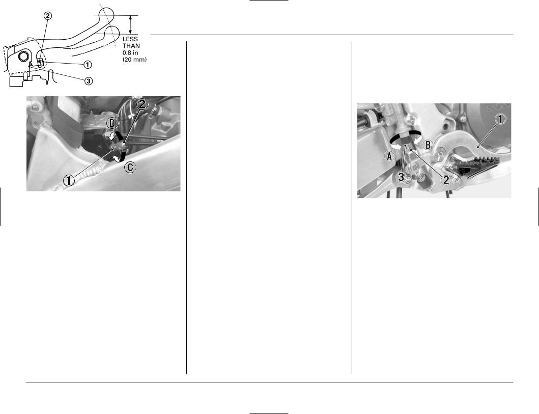
Front Brake Lever
The front brake lever position can be adjusted by Ioosening the lock nut and turning the adjuster. Turning the adjuster clockwise moves the brake lever farther away from the grip; turning the adjuster counterclockwise moves the brake lever closer to the grip.
Tighten the lock nut securely.
If the brake lever free play exceeds 0.8 in (20 mm), there is probably air in the brake system and it must be bled. Refer to the Honda Service Manual or see your authorized Honda dealer for brake bleeding.
CAUTION:
•Apply grease to the contacting faces of the adjuster and piston.
(1) ADJUSTER |
(2) LOCK NUT |
(3) PISTON |
Brake Pedal Height
The brake pedal height should be approximately level with the right footpeg.
To adjust the rear brake pedal height:
1.Loosen the lock nut and turn the adjusting bolt in direction A to raise the pedal, or in direction B to lower it.
2.Tighten the lock nut at the desired pedal height.
(1) |
REAR BRAKE PEDAL (2) LOCK NUT |
(3) |
ADJUSTING BOLT |
(A)RAISE THE PEDAL HEIGHT
(B)LOWER THE PEDAL HEIGHT
7
1. OPERATING INSTRUCTIONS
ADJUSTMENT FOR PERSONAL FIT
Control Positioning
•Position the control levers so that control use is comfortable when both seated and standing.
•Adjust control lever mounting bolt torque so that the levers will rotate on the handlebar in a fall, rather than bending or breaking. Apply Honda Thread Lock or an equivalent to the threads of these bolts prior to adjustment to help ensure the correct torque is retained. Tighten the top bolts first.
1
1
(1) CONTROL LEVER MOUNT BOLTS
•Position the shifter and brake pedal so that they are close to your boot for rapid access, but not so close that either is depressed when sitting or standing comfortably on the bike.
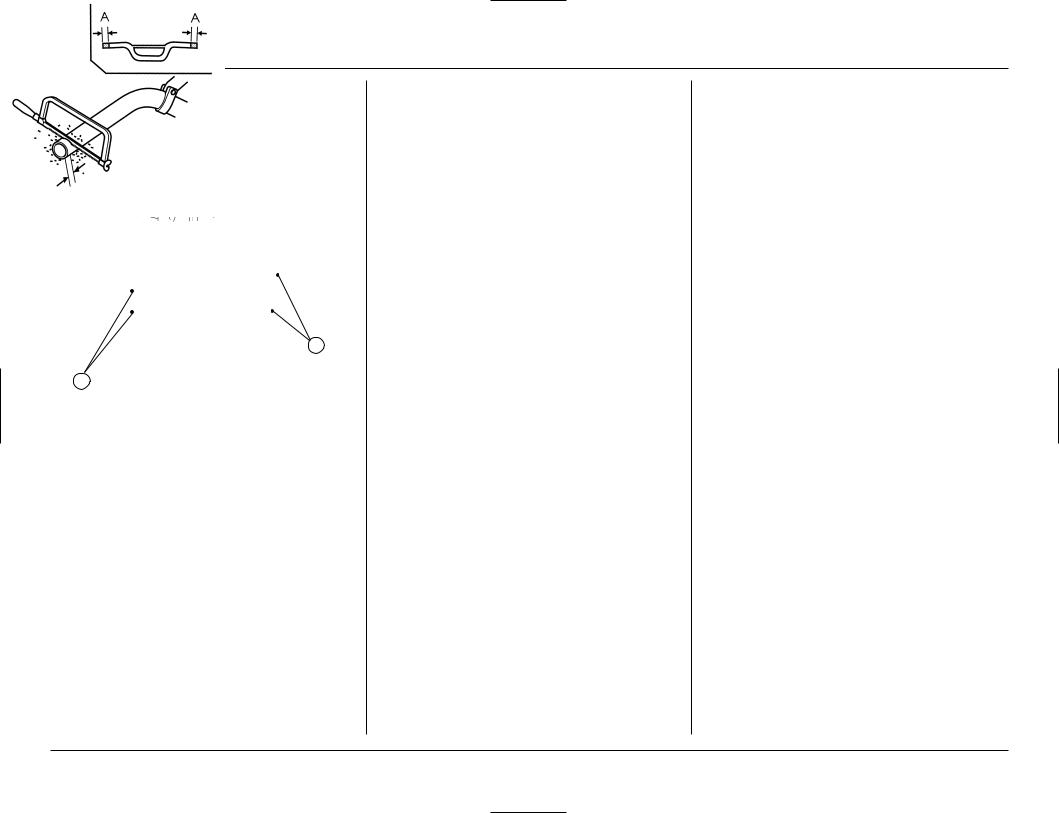
Handlebar Position, Width & Shape
•Position the handlebar so that both gripping the bar and operating the controls are comfortable while both seated and standing, while riding straight ahead and turning. Tighten the forward bolts first.
•The handlebar position may be moved rearward either 3 mm (using optional handlebar lower holders) or 6 mm (by rotating the standard holders 180 degrees). Refer to the Service Manual for installation instructions. Be sure to check the control cable and wiring harness routing after adjustment.
•Handlebar width can be trimmed with a hacksaw to better suit your particular shouIder width and riding preference. Think this through carefully and cut off just a small amount at a time from both sides equally. It is obviously much easier to make the handlebar narrower than it is to add material.
NOTE:
•Chamfer the edges to remove burrs and other irregularities or roughness after sawing the handlebar.
•An alternate handlebar shape, through varying rise or rearward sweep dimensions, will provide further adjustment to riding position and may better suit your particular body size or riding style. Each of the ergonomic dimensions of the machine were determined to suit the greatest possible number of riders based on an average size rider.
Additional Individualized Adjustments
•Initial suspension adjustments should be performed after a minimum of two hours of easy break-in time. Complete information on suspension adjustment is given in the Suspension Adjustment section.
•Optional front and rear suspension springs (front: stiffer and softer, rear: stiffer and softer) are available to tailor your CRF specifically for your weight, riding style and course conditions. Follow the instructions given in the rear suspension sag setting section of Suspension Adjustment to determine if your combined rider and sprung machine weight (rider fuIIy dressed for competition and machine coolant, oil and fuel levels ready for competition) requires an optional stiffer or softer rear spring. The use of the stiffer rear spring may need to be balanced by the use of the stiffer front spring.
•In order to further fine tune your CRF for specific course terrain and conditions, there is a choice of both higher and lower final drive ratios with two optional aluminum driven sprockets. For muddy or sandy courses, there is a more durable steel driven sprocket with the standard number of teeth. Like the optional springs, these sprockets are listed in the optional parts section of this manual.
8
2. SPECIFICATIONS
Item |
English |
Metric |
|
|
|
Dimension |
|
|
|
|
|
Overall length |
86.4 in |
2,194 mm |
Overall width |
32.6 in |
827 mm |
Overall height |
49.7 in |
1,262 mm |
Wheelbase |
58.9 in |
1,495 mm |
Seat height |
37.6 in |
954 mm |
Footpeg height |
16.9 in |
430 mm |
Ground clearance |
13.3 in |
338 mm |
Dry weight |
224.9 Ibs |
102 kg |
Frame
Type |
Twin tube |
||
|
|
||
|
Telescopic fork, |
||
F. suspension |
travel 11.1 in (281 mm) |
||
|
stroke 12.4 in (315 mm) |
||
R. suspension |
Pro-link, |
||
travel 12.6 in (319 mm) |
|||
|
|||
F. tire size, pressure |
80/100 – 21 M/C 51M |
||
psi (kPa, kgf/cm2) |
15 (100, 1.0) |
||
R. tire size, pressure |
110/90 – 19 M/C 62M |
||
psi (kPa, kgf/cm2) |
15 (100, 1.0) |
||
F. brake, swept area |
Single disc brake |
||
51.8 in2 (334.5 cm2) |
|||
|
|||
R. brake, swept area |
Single disc brake |
||
60.6 in2 (391.1 cm2) |
|||
|
|||
Fuel capacity |
2.0 US gal |
7.4 liter |
|
1.6 lmp gal |
|||
|
|
||
Caster angle |
26.91˚ |
||
Trail length |
4.3 in |
108 mm |
|
|
|
|
|
Fork oil capacity |
|
416 cm3 |
|
(except fork damper |
14.1 US oz |
||
per leg) |
|
|
|
|
|
|
|
|
Item |
English |
Metric |
|
|
|
|
|
|
Engine |
|
|
|
|
Type |
Liquid cooled, 4-stroke |
|||
|
|
|
|
|
Cylinder arrangement |
Single 6˚ inclined from |
|||
|
vertical |
|||
|
|
|
||
Bore and stroke |
3.78 x 2.44 in |
96.0 x 62.1 |
||
|
|
|
|
mm |
Displacement |
27.41 cu-in |
449.4 cm3 |
||
Compression ratio |
|
12.0 : 1 |
||
|
|
|
|
|
Engine oil capacity |
|
|
|
|
|
After draining |
0.70 |
US qt |
660 cm3 |
|
|
0.58 |
Imp qt |
|
|
|
|
||
|
|
|
|
|
|
After draining and |
0.73 |
US qt |
690 cm3 |
|
oil filter change |
0.61 |
Imp qt |
|
|
|
|||
|
After disassembly |
0.90 |
US qt |
850 cm3 |
|
|
0.75 |
Imp qt |
|
|
|
|
||
Transmission oil |
|
|
|
|
capacity |
|
|
|
|
|
After draining |
0.62 |
US qt |
590 cm3 |
|
|
0.52 |
Imp qt |
|
|
|
|
||
|
|
|
|
|
|
After disassembly |
0.71 |
US qt |
670 cm3 |
|
0.59 |
Imp qt |
||
Carburetor |
|
|
|
|
|
|
|
|
|
Type |
|
Piston valve |
||
|
|
|
|
|
Identification number |
|
FCR00C |
||
|
|
|
|
|
Main jet (standard) |
|
# 165 |
||
|
|
|
|
|
Jet needle (standard) |
|
NCYR |
||
|
|
|
|
|
Needle clip position |
|
4th groove |
||
(standard) |
|
|||
|
|
|
||
Slow jet (standard) |
|
# 42 |
||
|
|
|
|
|
Pilot screw opening |
|
1–1/2 turns out |
||
|
|
|
||
Float level |
0.31 in |
8.0mm |
||
|
|
|
|
|
|
Item |
English |
|
Metric |
|
|
|
|
|
Drive train |
|
|
|
|
|
Clutch type |
Wet, multi-plate type |
||
|
|
|
||
|
Transmission |
5-speed, constant mesh |
||
|
|
|
|
|
|
Primary reduction |
|
2.739 |
|
|
|
|
|
|
|
Gear ratio I |
|
1.800 |
|
|
|
|
|
|
|
Gear ratio II |
|
1.470 |
|
|
|
|
|
|
|
Gear ratio III |
|
1.235 |
|
|
|
|
|
|
|
Gear ratio IV |
|
1.050 |
|
|
|
|
|
|
|
Gear ratio V |
|
0.909 |
|
|
|
|
|
|
|
Final reduction |
|
3.692 |
|
|
|
|
||
|
Gear shift pattern |
Left foot-operated return |
||
|
system 1-N-2-3-4-5 |
|||
|
|
|||
|
|
|
|
|
Electrical |
|
|
|
|
|
|
|
|
|
|
Ignition |
|
CDl |
|
|
|
|
||
|
Starting system |
Kickstarter |
||
|
|
|
|
|
|
Spark plug : |
NGK |
|
|
|
IFR8H11 |
|||
|
Standard |
|||
|
DENSO |
|
|
|
|
|
|
|
|
|
|
VK24PRZ11 |
||
|
|
|
|
|
|
For extended high |
NGK |
|
|
|
IFR9H11 |
|||
|
speed riding |
|||
|
DENSO |
|
|
|
|
|
|
|
|
|
|
VK27PRZ11 |
||
|
|
|
|
|
9
3. OPTIONAL PARTS
OPTIONAL PARTS LIST
These parts and tools may be ordered from your authorized Honda dealer.
CARBURETOR |
Remarks |
||
Main jet |
#155 – #175 (in increments of |
||
(Standard: #165) |
2 |
|
|
|
|
|
|
|
165 |
|
|
|
|
|
|
Slow jet |
#38 – #48 |
||
(Standard: #42) |
(in increments of 2 or 3) |
||
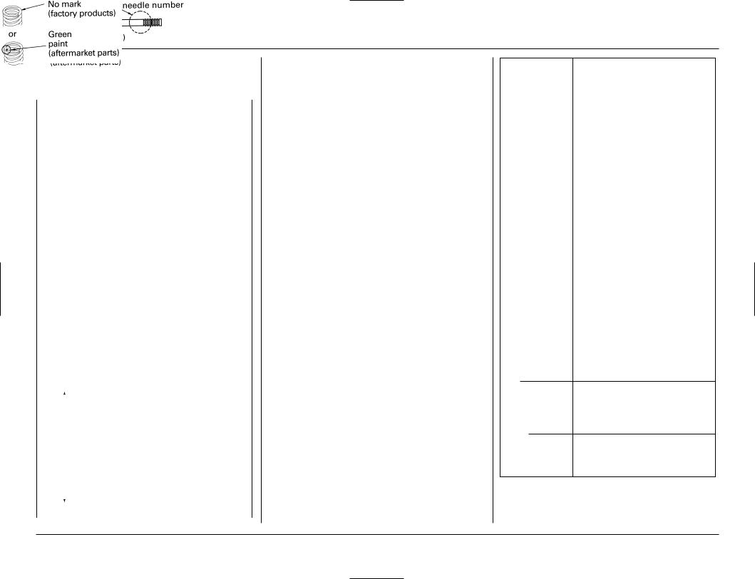
Jet Needles
Standard needle: NCYR
Straight diameter: ø2.755 mm
|
|
|
|
Jet needle number |
Jet needle number |
||||
|
|
|
|
(standard series) |
(1/2 clip position |
||||
|
|
|
|
|
|
|
richer than |
||
|
|
|
|
|
|
|
standard series. |
||
|
|
|
|
|
|
|
richer only at 1/8 |
||
|
|
|
|
|
|
|
to 3/4 throttle) |
||
|
|
|
|
|
|
|
|
|
|
|
|
|
|
78.700 |
|
7859.250.41 mm |
|
||
|
|
|
|
|
58.96 mm |
|
|
|
|
|
|
|
|
|
|
|
|
|
|
characteristics |
Richer |
|
throttle)1/4 |
NCYP |
NCVP |
||||
|
Ø2.735 mm |
Ø2.735 mm |
|||||||
|
|
|
|
||||||
|
|
|
|
|
|
|
|
|
|
|
|
|
|
NCYQ |
NCVQ |
||||
|
|
|
|
Ø2.745 mm |
Ø2.745 mm |
||||
|
|
|
|
|
|
|
|
|
|
|
|
|
|
(standard needle) |
NCVR |
||||
Generalflow |
|
|
(at1/16 to |
NCYR |
|||||
Leaner |
|
Ø2.755 mm |
Ø2.755 mm |
||||||
|
NCYT |
NCVT |
|||||||
|
|
|
|
NCYS |
NCVS |
||||
|
|
|
|
Ø2.765 mm |
Ø2.765 mm |
||||
|
|
|
|
Ø2.775 mm |
Ø2.775 mm |
||||
|
|
|
|
||||||
|
|
|
|
|
|
|
|
|
|
|
|
FRAME |
Remarks |
|
|
|
|
Driven sprocket |
< >: Drive chain links |
||
|
Standard |
48 Teeth, Aluminum. |
|
|
|
|
<114> |
Optional |
47 Teeth, Aluminum |
||
|
|
|
<112> |
|
|
|
49 Teeth, Aluminum |
|
|
|
<114> |
Handlebar |
|
||
lower holder |
|
||
|
Standard |
3 mm offset |
|
Optional |
no offset |
||
|
|
|
|
Front wheel |
21 inch |
||
|
Standard |
||
|
|
|
Fork height: 0.3 in (7.0 mm) |
|
|
|
(align the index groove with the |
|
|
|
top of the upper clamp) |
|
|
|
|
Optional |
20 inch |
||
|
|
|
• wheel assembly |
|
|
|
(except brake disk) |
|
|
|
• tire tube |
|
|
|
• tire flap |
|
|
|
• rim lock (bead stopper) |
|
|
|
• front tire |
|
|
|
(90/100-20, 90/100-20 M/C) |
|
|
|
Fork height: 0 in (0 mm) |
|
|
|
(align the top of the fork tube |
|
|
|
with the top of the upper clamp) |
|
|
|
|
TOOLS |
Remarks |
|
|
Pin spanner A |
To adjust spring preload. |
|
(two spanners required) |
|
|
Workstand |
For maintenance |
|
|
Air gauge |
For checking tire air pressure. |
|
|
|
FRAME |
|
Remarks |
||
Shock spring |
|
|
|
||
Standard |
308.0 lbf/in (5.50kgf/mm) |
||||
|
|
|
|
No mark |
|
|
|
|
|
(factory products) |
|
|
|
|
or |
Red |
|
|
|
|
|
paint |
|
|
|
|
|
(aftermarket parts) |
|
|
|
|
|
|
|
|
|
|
|
|
|
Optional |
|
|
|
||
|
|
Softer |
296.8 lbf/in (5.30kgf/mm) |
||
|
|
|
|
|
|
|
|
Stiffer |
319.2 lbf/in (5.70kgf/mm) |
||
|
|
|
330.4 lbf/in (5.90kgf/mm) |
||
|
|
|
|
||
Fork spring |
|
|
|
||
Standard |
26.32 lbf/in (0.47kgf/mm) |
||||
Optional |
|
Softer |
25.20 lbf/in (0.45kgf/mm) |
Stiffer |
27.44 lbf/in (0.49kgf/mm) |
The standard fork spring and shock spring mounted on the motorcycle when it leaves the factory are not marked. Before replacing the springs, be sure to mark them so they can be distinguished from other optional springs.
10

4. SERVICE AND MAINTENANCE
PRE-RIDE INSPECTION CHECK LIST
Pre-ride Inspection
 WARNING
•If the Pre-ride and Pre-race inspection are not performed, severe personal injury or vehicle damage may result.
• |
Engine oil level ................................................... |
21 |
• |
Transmission oil level ......................................... |
23 |
• |
Coolant level ....................................................... |
24 |
• Cooling system and hoses for condition .......... |
24 |
|
• Spark plug for proper heat range, carbon |
|
|
|
fouling and high tension cord terminal for |
|
|
looseness ....................................................... |
25 |
• Air cleaner for condition and contamination ... |
27 |
|
• Clutch operation and free play .......................... |
5 |
|
• Hot starter operation and free play ................... |
6 |
|
• Breather drain for cleaning ................................ |
27 |
|
•Steering head bearings and related parts for
condition ........................................................ |
47 |
• Carburetor throttle operation.......................... |
6, 47 |
•Engine idle speed for stable and proper
RPM ................................................................ |
26 |
•Tires for damage or improper inflation
pressure ......................................................... |
49 |
• Spokes for looseness ......................................... |
49 |
• Rim locks for looseness ..................................... |
49 |
• Front and rear suspension for proper |
|
operation ................................................. |
49, 50 |
• Front and rear brakes, check operation ......... |
7, 51 |
•Drive chain for correct slack and adequate
lubrication ...................................................... |
52 |
•Drive chain guide, sliders and guide rollers for
damage or wear ............................................ |
54 |
• Every possible part for looseness (such as |
|
cylinder head nuts, engine mounting bolts, |
|
axle nuts, handlebar holder bolts, fork triple |
|
clamp bolts, drive chain adjuster, drive chain |
|
guide, wire harness connectors, kickstarter |
|
mounting bolt, etc.) ...................................... |
58 |
MAINTENANCE SCHEDULE
Perform the Pre-ride Inspection at each scheduled maintenance period.
l: Inspect and Clean, Adjust, Lubricate or Replace if necessary. C: Clean. R: Replace. L: Lubricate.
|
FREQUENCY |
|
Each race |
|
|
|
|
|
|
NOTE |
or about |
ITEMS |
|
|
2.5 hours |
|
|
|
|
THROTTLE OPERATION |
|
I |
|
HOT START SYSTEM |
|
I |
|
AIR FILTER |
|
(NOTE 1) |
C |
CRANKCASE BREATHER |
|
I |
|
SPARK PLUG |
|
|
I |
RADIATOR COOLANT |
(NOTE 2) |
I |
|
VALVE CLEARANCE / DECOMPRESSOR SYSTEM |
(NOTE 4) |
|
|
ENGINE OIL |
|
(NOTE 3) |
|
ENGINE OIL FILTER |
(NOTE 3) |
|
|
ENGINE IDLE SPEED |
|
I |
|
PISTON AND PISTON RINGS |
|
|
|
PISTON PIN |
|
|
|
TRANSMISSION OIL |
|
|
|
COOLING SYSTEM |
|
I |
|
DRIVE CHAIN |
|
|
I,L |
DRIVE CHAIN SLIDER |
|
I |
|
DRIVE CHAIN ROLLER |
|
I |
|
DRIVE SPROCKET |
|
I |
|
DRIVEN SPROCKET |
|
I |
|
BRAKE FLUID |
(NOTE 2) |
I |
|
BRAKE PADS WEAR |
|
I |
|
BRAKE SYSTEM |
|
I |
|
CLUTCH SYSTEM |
|
I |
|
CONTROL CABLES |
|
I,L |
|
EXHAUST PIPE/MUFFLER |
|
I |
|
SUSPENSION |
|
I |
|
SWINGARM/SHOCK LINKAGE |
|
|
|
FORK OIL |
FORK TUBE/SLIDER |
(NOTE 3) |
|
DAMPER |
|
|
|
|
|
|
|
NUTS, BOLTS, FASTENERS |
|
I |
|
WHEELS/TIRES |
|
I |
|
STEERING HEAD BEARINGS |
|
|
|
Every 3 |
Every 6 |
Every 9 |
Every 12 |
races |
races |
races |
races |
or about |
or about |
or about |
or about |
7.5 hours |
15.0 hours |
22.5 hours |
30.0 hours |
I
R
R
R
R
R
R
L
R
R
I
This maintenance schedule is based upon average riding condition. Machine subjected to severe use require more frequent servicing.
NOTE: 1.Clean after every moto for dusty riding condition.
2.Replace every 2 years. Replacement requires mechanical skill. 3.Replace after the first break-in ride.
4.Inspect after the first break-in ride.
Ref. Page
6
6
27
27
25
24
30
21
21
26
39
39
23
24
52
54
54
53 53, 55 51 52
7 5, 28 57 55 49, 50 16, 50 75 83 58 49 47
11
4. SERVICE AND MAINTENANCE
GENERAL SERVICE INFORMATION
•Perform maintenance on firm, level ground using the optional workstand or equivalent support.
•Always install new gaskets, O-rings, cotter pins, piston pin clips, snap rings, etc. when reassembling.
•When tightening bolts, nuts or screws, start with the larger diameter or inner fasteners, and tighten them to the specified torque using a crisscross pattern.
•Use genuine Honda parts or their equivalent when servicing your CRF.
•Clean parts in non-flammable cleaning solvent when disassembling. Lubricate any sliding surface, O- rings. and seals before reassembling.
 WARNING
•Gasoline or low flash point solvents are highly flammable or explosive and must never be used for cleaning parts or the air filter element. Fire or explosion could result.
•After reassembling, check all parts for proper installation and operation.
•Grease parts by coating or filling where specified.
NOTE :
•Specifications are listed on page 9.
BETWEEN MOTO/BETWEEN PRACTICE AND MOTO MAINTENANCE
•Dirt = wear and weight. Clean accumulated dirt from under fenders and off of wheels, suspension, grips, controls and footpegs. A stiff, nylon parts cleaning brush works well.
•Check tire air pressure.
•Check spoke tension and rim lock nut security.
•Check sprocket bolt and nut security.
•Clean chain with a stiff, nylon parts cleaning brush; lubricate and adjust as necessary.
 WARNING
•Do not perform maintenance while engine is running. Injury to your lingers or hands may result.
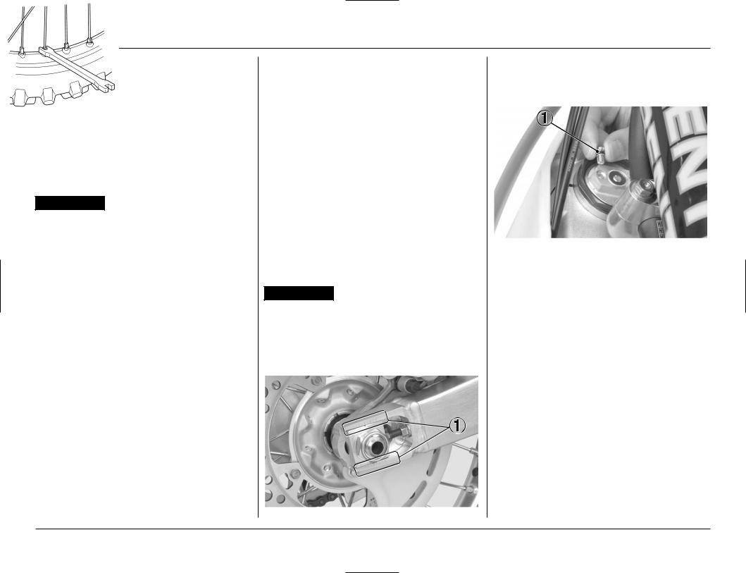
•After adjustment, check that the chain adjuster index marks are in the same position on each side to be sure the rear wheel is in proper alignment. This is especially important for best performance from the rear disc brake and to extend pad wear.
(1) CHAIN ADJUSTER INDEX MARKS
•Release the built-up pressure in the fork tubes (in excess of normal atmospheric pressure: 0 psi) caused by normal fork action while riding. The front wheel should be suspended above ground for this operation.
( I ) PRESSURE RELEASE SCREWS
12
AFTER RACE MAINTENANCE
It is important to the long term performance of your CRF to properly maintain your racebike at all times. If you envision the maintenance cycle ending as the machine is fully prepared for practice at the next event and beginning again after that practice, there is clearly work to do in between. After the race is a good place to begin your routine maintenance.
After Race Lubrication
Apply a light coating of rust-inhibiting oil to the drive chain, drive sprocket and any steel portions of the chassis or engine where the paint has worn away and the exposed metal can begin to rust. Apply this rustinhibiting oil more heavily if the event was particularly wet or muddy.
 WARNING
•Take care to prevent catching your fingers between the chain and sprocket.
Routine Cleaning
If the machine is only slightly dirty, it is best to clean it by hand with the aid of a stiff bristled nylon brush and some clean rags. There is no reason to introduce unnecessary moisture.
 WARNING
•Take care to prevent catching your fingers between the chain and sprocket.
Allow enough time to completely clean and dry your CRF to reduce the possibility of corrosion or rust.
Accumulated dirt should be loosened with a shower of water; then brushed away with suitable brushes, soap and water; then the machine rinsed with clean water and wiped completely dry.
A variety of reasonably priced cleaning brushes are available from variety, drug, food and hardware stores that are extremely useful in removing dirt from the many tight contours of your machine.
Pressurized Spray Washers
CAUTION:
•There are some areas on your CRF that you should never directly aim the nozzle of a high pressure spray washer. It is tempting to let the pressure of the water remove all the dirt that has accumulated, but control yourself. The force of the water under this extreme pressure can penetrate the dust seals of the suspension pivot points and steering head bearings–driving dirt inside and needed lubrication out. Avoid spraying water under the seat and fuel tank and into the airbox as well.
1
2
(1)STEERING HEAD BEARINGS
(2)SUSPENSION PIVOT POINTS
Condensation Control
Some condensation can form within the transmission cavity as well. This is natural and just one more reason you should change the transmission oil often.
After Cleaning Lubrication
Although you can basically follow the suggestions given in the Maintenance section under General Maintenance (pages 14 –16), there are some things you should do just after washing your CRF to help prevent rust and corrosion.
Once your CRF is clean and dry, you should protect any bare steel from rusting by applying a light coating of a rust-inhibitor. Lubricate the drive chain and drive sprocket after removing and thoroughly cleaning in solvent. Be sure the chain is wiped clean and is dry before applying the chain lube.
Follow the suggestions given in the pages of this manual for lubricating items such as the brake and clutch lever pivot points and footpeg pivot pins.
13
4. SERVICE AND MAINTENANCE
GENERAL MAINTENANCE
•Spark Plugs: Some non-resistor plugs may cause ignition problems. Refer to the recommendations elsewhere in this manual for specific types so you will be sure to use the proper reach and heat range. Replace periodically as specified in the Maintenance Schedule. (pages 11, 25)
•Spark Plug Cap: Install a small plastic tie-wrap around the spark plug cap to reduce any possibility of it loosening or of water penetration.
•Engine Oil and Filter: Drain and replace engine oil often to ensure the greatest service life of the piston, cylinder and crankshaft.
Also replace engine oil filter often to ensure the greatest service life. Frequent changes will also assure consistent performance of power and response. (page 21).
• Transmission Oil: Drain and replace transmission oil often to ensure the greatest service life of the transmission and clutch. Frequent changes will also assure consistent performance of both shifting and clutch action.(page 23)
•Air Cleaner: Clean and oil your air cleaner regularly because the volume of air able to pass through it has a great effect on performance. Both engine performance and long term durability may be affected by an air cleaner that has deteriorated and allows dirt to pass. Inspect the air cleaner closely each time it's serviced for evidence of small tears or seam separation. Keep a spare air cleaner oiled and ready to install, sealed in a plastic bag. Riding in dusty conditions may require servicing the air cleaner or replacing it with a pre-serviced air cleaner between motos. Be careful not to over oil the air cleaner. While it is important to oil the air cleaner thoroughly, over oiling will cause an overall rich running condition, probably more noticeable off idle and in low rpm performance. Follow the servicing instructions in the Maintenance section. Use Pro Honda Foam Filter Oil or an equivalent. Be sure to grease the air cleaner flange where it contacts the air cleaner housing. Honda White Lithium Grease, or an equivalent, is handy for this because any dirt that penetrates this sealing area will show up clearly. (page 27)
Use the Honda genuine air cleaner or an equivalent air cleaner specified for your model.
Using the wrong Honda air cleaner or a non-Honda air cleaner which is not of equivalent quality may cause premature engine wear or performance problems.
•Air Box Sealing: Remove and reseal the air cleaner housing boot where it connects to the air cleaner housing with silicone sealer if there is any doubt to its sealing integrity. Use Hondalock or an equivalent on the attaching studs. Inspect the air cleaner and air intake tract regularly for signs of deterioration or dirt penetration.
14
•Handgrips: Always use Honda Hand Grip Cement (U.S.A. only) or Honda Bond A when replacing handgrips.
Throttle grip: Align the index mark on the throttle grip with the index mark of the throttle cable guide. Left handlebar grip: Align the " " mark on the left handlebar grip with the paint mark on the handlebar. Refer to the Service Manual for installation instructions.
For added security, you may choose to safety wire the hand grips to the handlebar and throttle to prevent the possibility of them loosening. Position the twisted wire ends away from your palms and be sure to bend the wire ends well into the grip rubber so they will not snag your glove.
•Throttle Control: Remove the throttle control every few rides, clean the inside of the drum and the handlebar thoroughly, and apply a light coating of silicone lubricant. Inspect the cable carefully for kinks or other damage that may restrict throttle control in anyway. Move the handlebar from lock to lock to be sure there is no cable interference. Check to be sure the top of the carburetor is screwed on tight. Make certain the throttle operation is perfect after servicing and inspecting.
•Fuel Filter: Periodically drain the fuel from the tank, remove and clean the fuel filter. Replace the fuel filter O-ring if there are any signs of damage or deterioration. (page 48)
•Fuel Contamination: Periodically drain the float bowl and inspect the carburetor for contamination from dirt. (page 62)
•Engine Mounting Bolts: Make sure the engine mounting bolts are tightened to the proper torque specification. For added peace of mind, remove the nuts, clean the threads, and apply Honda Thread Lock or an equivalent prior to torquing the nuts.
•Gaskets: Always use new gaskets when reassembling components.
•Cylinder Removal: Put a little grease on the cylinder mounting dowels to prevent corrosion from dissimilar metals. The tolerances are quite tight, so it's important to keep these dowels absolutely clean.
•Electrical Connectors: Clean electrical connectors and wrap them with electrical tape to reduce the possibility of unwanted disconnections, water shorts or corrosion. Additional corrosion protection is offered by using Honda Dielectric Grease on all electrical connections.
15
4. SERVICE AND MAINTENANCE
•Suspension Linkage Lubrication: Disassemble, clean, inspect and lubricate all pivot bearings after each 7.5 hours of running time in order to maintain proper suspension performance and minimize component wear. Use Honda Moly 60 Paste (U.S.A. only) or molybdenum disulfide paste (containing more than 40% molybdenum disulfide additive).
•Swingarm Pivot Lubrication: Clean, inspect and lubricate when servicing suspension linkage pivots. Be sure all of the suspension pivot seals are in good condition. Use Honda Moly 60 Paste (U.S.A. only) or molybdenum disulfide paste (containing more than 40% molybdenum disulfide additive).
•Swingarm: Do not attempt to weld or otherwise repair a damaged swingarm. Welding will weaken the swingarm.
•Footpegs: Worn footpeg teeth can be repaired by filing the grooves between the teeth with a trian- gular-shaped file. Be aware that filing them too sharp will reduce boot sole lifespan. Sharpen only the points of the teeth. Filing the grooves deeper will weaken the footpegs. Be sure the pegs are free to pivot freely and that the pivot pin retaining cotter pins are in good condition.
•Brake Fluid Replacement: Replace the hydraulic fluid in the brake system every two years.
•Water Pump Inspection Hole: After every race, check the inspection hole, located just below the water pump cover on the right crankcase cover. Clean away any clogged dirt or sand, if necessary. Look for coolant or oil leakage. Leaking coolant indicates a worn or damaged water seal. Leaking oil indicates a bad transmission oil seal. If replacement is necessary, both seals should be replaced.
•Brake Caliper Inspection: Be sure both front and rear calipers are able to move freely on the caliper bracket pins. Check pad thickness periodically and replace when minimum thickness is reached.
•Steering Head Bearings: Periodically clean, inspect and regrease the steering head bearings―especially if wet, muddy or extremely dusty courses are encountered often.
•Fork Oil/Performance: Disassemble, clean and inspect the fork and replace the oil regularly. Contamination due to the tiny metal particles produced from the normal action of the fork, as well as normal oil breakdown, will deteriorate the performance of the suspension. Refer to the Honda Service Manual. Use only Pro Honda HP Fork Oil 5W or equivalent which contains special additives to assure maximum performance of your CRF's front suspension.
Frame: Because your CRF is a high-performance machine, the frame should not be overlooked as part of your overall competition maintenance program. Periodically inspect the frame closely for possible cracking or other damage. It makes good racing sense.
•Spokes: Check spoke tension frequently between the first few rides. As the spokes, nipples and rim contact points seat-in, the spokes may need to be retightened. Once past this initial seating-in period, the spokes should hold their tension. Still, be sure your race maintenance program includes checking spoke tension and overall wheel condition on a regular basis. (page 49)
•Nuts, Bolts, Etc.: Application of a thread locking agent to essential fasteners offers added assurance and security. Remove the nuts, clean the threads of both the nuts and bolts, apply Honda Thread Lock or an equivalent and tighten to the specified torque.
16
MAINTENANCE PREPARATIONS
SEAT
Seat Removal
1.Remove the seat bolts and collars.
2.Slide the seat back.
1
2
(1) SEAT BOLTS |
(2) SEAT |
Seat Installation
1.Slide the seat front prong onto the seat bracket and the seat rear prongs onto the tabs by pushing down and forward on the seat in each of these areas.
2.Install the collars and tighten the seat bolts.
TORQUE: 20 lbf ft (26 N m, 2.7 kgf m)
1 3
|
2 |
|
4 |
|
|
|
|
(1) |
SEAT FRONT PRONG |
(2) |
SEAT BRACKET |
(3) |
SEAT REAR PRONGS |
(4) |
TABS |
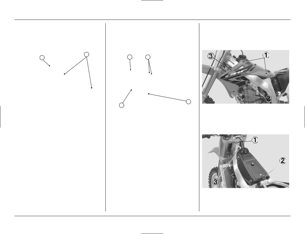
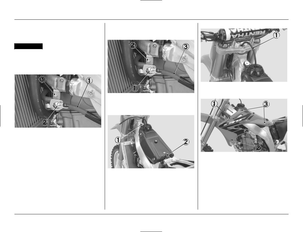
FUEL TANK
Fuel Tank Removal
1.Turn the fuel valve OFF.
2.Remove the seat (this page).
3.Remove the shroud A bolts and collars.
4.Remove the shroud B bolts, collars and shrouds.
(1)SHROUD A BOLTS/COLLARS
(2)SHROUD B BOLTS/COLLARS
(3)SHROUD
5.Pull the breather tube out of the steering stem nut.
6.Unhook and remove the fuel tank band.
7.Remove the fuel tank bolt.
(1)BREATHER TUBE
(2)FUEL TANK BAND
(3)FUEL TANK BOLT
17
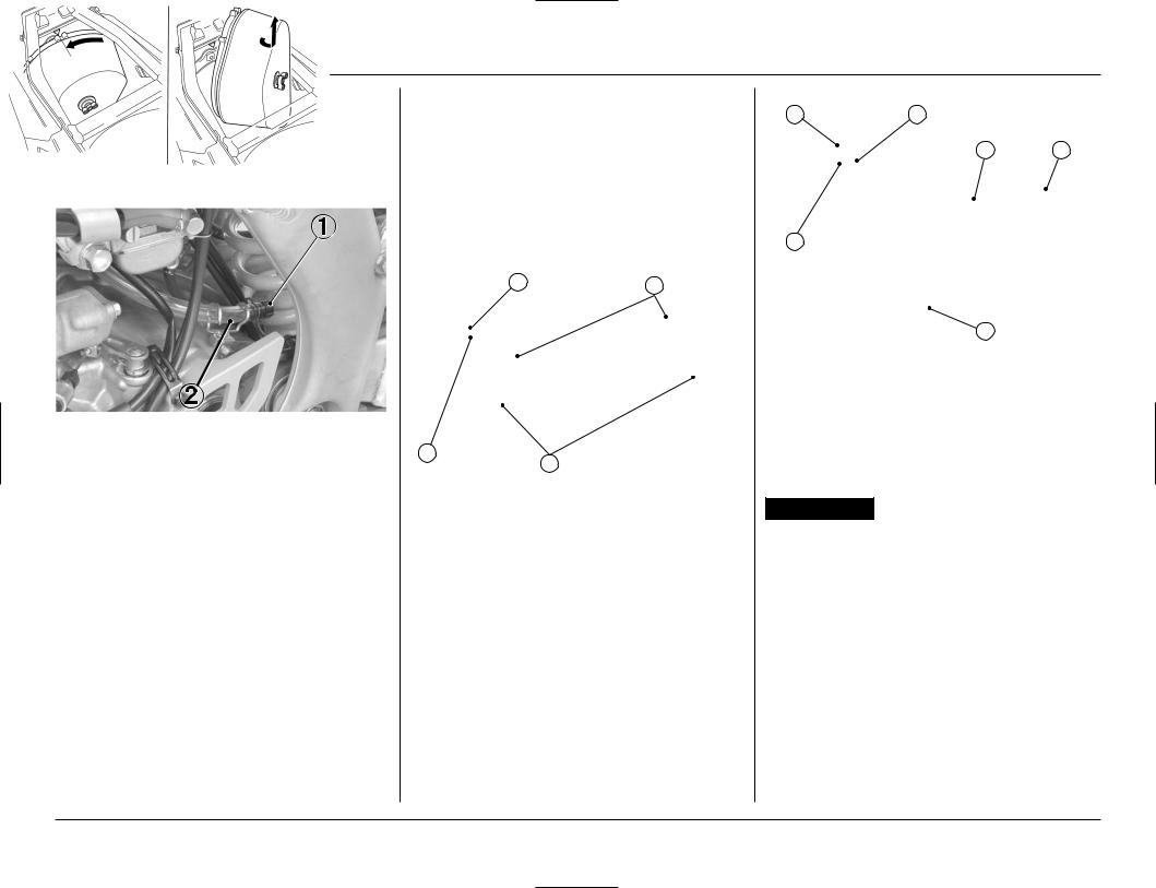
4. SERVICE AND MAINTENANCE
8. |
Disconnect the fuel line from the fuel valve. |
Fuel Tank Installation |
6. Put the breather tube in the steering stem nut. |
|
|
The fuel line leading to the carburetor must be dis- |
1. |
Install the fuel tank on the frame. |
|
|
connected, not the fuel line leading to the fuel tank. |
2. |
Install the fuel valve and fuel valve bolt. |
|
9. |
Remove the fuel valve bolt and fuel valve. |
3. |
Connect the fuel line. |
|
10. Remove the fuel tank. |
|
|
|
|
 WARNING
•Gasoline is extremely flammable and is explosive under certain conditions. Perform this operation in a well-ventilated area with the engine stopped. Do not smoke or allow flames or sparks in the area where gasoline is drained or stored and where the fuel tank is refueled.
|
|
|
(1) BREATHER TUBE |
|
|
|
|
7. |
Install the shrouds, collars and shroud B bolts. |
(1) |
FUEL VALVE |
(2) FUEL VALVE BOLT |
8. |
Install the collars and shroud A bolts. |
(3) |
FUEL LINE |
|
|
|
4.Install the fuel tank bolt.
5.Hook the fuel tank band.
(1) |
FUEL LINE |
(2) FUEL VALVE |
(3) |
FUEL VALVE BOLT |
|
|
|
(1) |
SHROUD |
|
|
(2) |
SHROUD B BOLTS/COLLARS |
|
|
(3) |
SHROUD A BOLTS/COLLARS |
(1) |
FUEL TANK BOLT |
9. Install the seat (page 17) |
|
(2) |
FUEL TANK BAND |
|
|
18
SUBFRAME
Subframe Removal
1.Remove the seat (page 17).
2.Remove the side cover bolts, collars and side covers.
(1)SEAT
(2)SIDE COVER BOLTS/COLLARS
(3)SIDE COVER
3.Loosen the muffler clamp bolt.
4.Remove the muffler A bolt, muffler B bolt/washer and muffler.
(1)MUFFLER CLAMP BOLT
(2)MUFFLER A BOLT
(3)MUFFLER B BOLT/WASHER
(4)MUFFLER
5.Disconnect the crankcase breather tube.
6.Loosen the screw on the air cleaner connecting tube clamp.
(1)CRANKCASE BREATHER TUBE
(2)SCREW
(3)AIR CLEANER CONNECTING TUBE CLAMP
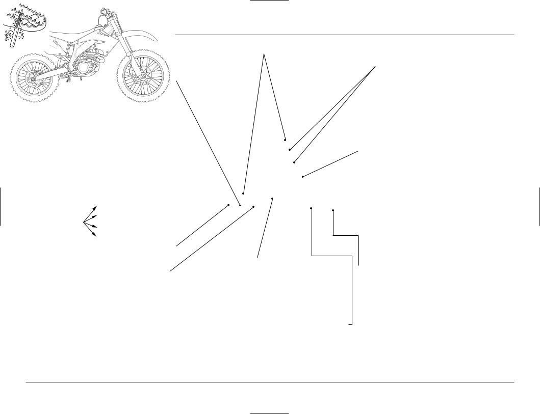
7.Remove the subframe mounting A bolts and subframe mounting B bolt. Then remove the subframe by pulling it straight backward.
(1)SUBFRAME MOUNTING A BOLTS
(2)SUBFRAME MOUNTING B BOLT
(3)SUBFRAME
Subframe Installation
1.Loosely attach the upper and lower ends of the subframe to the mainframe while connecting the air cleaner connecting tube to the carburetor. Then align the subframe with the rear wheel and tighten the subframe mounting B bolt and subframe mounting A bolts.
TORQUE:
B bolt: 22 lbf ft (30 N m, 3.1 kgf m)
A bolt: 36 lbf ft (49 N m, 5.0 kgf m)
(1)SUBFRAME
(2)SUBFRAME MOUNTING B BOLT
(3)SUBFRAME MOUNTING A BOLTS
19

4. SERVICE AND MAINTENANCE
2.Tighten the screw on the air cleaner connecting tube clamp.
3.Connect the crankcase breather tube.
(1)SCREW
(2)AIR CLEANER CONNECTING TUBE CLAMP
(3)CRANKCASE BREATHER TUBE
4.Remove the gasket.
5.Install the muffler clamp and new gasket to exhaust pipe.
(1) MUFFLER CLAMP |
(2) GASKET |
6.Install the muffler.
7.Install the muffler clamp by aligning the tab of the muffler clamp with the cut-out of the muffler.
1
4
3
2
(1) |
MUFFLER |
(2) |
MUFFLER CLAMP |
(3) |
TAB |
(4) |
CUT–OUT |
8.Tighten the muffler B bolt and muffler A bolt.
TORQUE: 16 lbf ft (22 N m, 2.2 kgf m)
9.Tighten the muffler clamp bolt.
TORQUE: 15 lbf ft (21 N m, 2.1 kgf m)
(1)MUFFLER
(2)MUFFLER B BOLT
(3)MUFFLER A BOLT
(4)MUFFLER CLAMP BOLT
10.Install the side covers, side cover bolts and collars.
11.Install the seat (page 17).
(1)SIDE COVER
(2)SIDE COVER BOLTS/COLLARS
(3)SEAT
20
MAINTENANCE PROCEDURES
ENGINE OIL
Inspecting and Adding Engine Oil
1.Run the engine at idling for a few minutes, then shut it off.
2.Wait three minutes after shutting off the engine to allow the oil to properly distribute itself in the engine.
3.Support the CRF in an upright position on a level surface.
4.Check that the oil level is between the upper and lower level marks in the inspection window.
•If the oil is at or near the upper level mark, you do not have to add oil.
•If the oil is below or near the lower level mark, remove the engine oil filler cap and add the recommended oil until it reaches the upper level mark. (Do not overfill)
Reinstall the engine oil filler cap. Repeat steps 1–4.
5.Check for oil leaks.
(1)UPPER LEVEL MARK
(2)LOWER LEVEL MARK
(3)INSPECTION WINDOW
(4)ENGINE OIL FILLER CAP
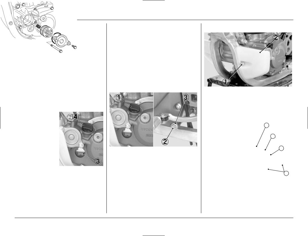
Replacing Engine Oil and Filter
1.Run the engine at idling for a few minutes, then shut it off.
2.Support the CRF in an upright position on a level surface.
3.Remove the engine oil filler cap from the left crankcase cover.
4.Place an oil drain pan under the engine to catch the oil. Then remove the engine oil drain bolt and sealing washer.
5.With the engine stop button pushed, repeat kickstarter operation approximately 5 times to drain the engine oil completely.
6.After the oil has drained, install the engine oil drain bolt with a new sealing washer.
TORQUE: 12 lbf ft (16 N m, 1.6 kgf m)
(1)ENGINE OIL FILLER CAP
(2)ENGINE OIL DRAIN BOLT
(3)SEALING WASHER
7.It is recommended to replace the oil and filter every 6 races or about every 15.0 hours. However, if you replace only the oil before the recommended interval, see step 15 (page 22).
8.Remove the left engine guard bolt and left engine guard.
(1)LEFT ENGINE GUARD BOLT
(2)LEFT ENGINE GUARD
9.Remove the oil filter cover bolts and oil filter cover.
10.Remove the oil filter from the cover.
11.Check that the oil filter cover O-ring is in good condition.
3
4
2
1
(1)OIL FILTER COVER BOLTS
(2)OIL FILTER COVER
(3)OIL FILTER
(4)OIL FILTER COVER O-RING
21
4. SERVICE AND MAINTENANCE
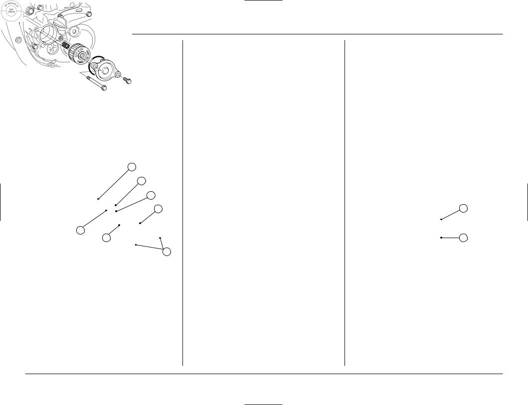
12.Apply grease to the seat face of spring.
13.Position the spring against the engine crankcase and install a new oil filter with the rubber seal facing out, away from the engine. You should see the ”OUTSIDE” mark on the filter body, near the seal.
Use a new genuine Honda oil filter or a filter of equal quality specified for your model.
CAUTION:
• If the oil filter is not installed properly, it will cause serious engine damage.
14. Install the oil filter cover, then tighten the oil filter cover bolts.
TORQUE: 7 lbf ft (10 N m, 1.0 kgf m)
1
2
3
6
4
5
7
(1)SPRING
(2)OIL FILTER
(3)RUBBER SEAL
(4)OUT-SIDE MARK
(5)O-RING
(6)OIL FILTER COVER
(7)OIL FILTER COVER BOLTS
15. Install the left engine guard and left engine guard bolt.
16.Fill the crankcase with the recommended oil. capacity: 0.73 US qt (0.69 liter, 0.61 Imp qt)
at oil and filter change
0.70US qt (0.66 liter, 0.58 Imp qt) at oil change
17.Install the engine oil filler cap.
18.Check the engine oil level by following the steps in Inspecting and Adding Engine Oil (page 21).
Recommended Engine Oil
Use Pro Honda GN4, HP4 (without molybdenum additives) or HP4M (with molybdenum additives) 4-stroke oill, or an equivalent.*
API |
SG or higher except oils labeled as |
classification |
energy conserving on the circular |
|
API service label |
|
|
viscosity |
SAE 10W-40 |
(weight) |
|
|
|
JASO T 903 |
MA or MB |
|
|
*Suggested oils are equal in performance to SJ oils that are not labeled as energy conserving on the circular API service label.
•Your CRF does not need oil additives. Use recommended oil.
•Do not use API SH or higher oils displaying a circular API ”energy conserving” label on the container. They may affect lubrication.
NOT RECOMMENDED |
OK |
CAUTION:
•Oil is a major factor affecting the performance and service life of the engine.
Nondetergent, vegetable, or castor based racing oils are not recommended.
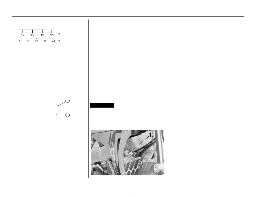
Other viscosities shown in the chart below may be used when the average temperature in your riding area is within the indicated range.
JASO T 903 standard
The JASO T 903 standard is an index to choose engine oils for 4-stroke motorcycle engines.
There are two classes: MA and MB.
Oil conforming to the standard has the following classification on the oil container.
1
2
(1)CODE NUMBER OF THE SALES COMPANY OF THE OIL
(2)OIL CLASSIFICATION
22
TRANSMISSION OIL
Inspecting and Adding Transmission Oil
1.Run the engine at idling for a few minutes, then shut it off.
2.Wait three minutes after shutting off the engine to allow the oil to properly distribute itself in the clutch and transmission.
3.Support the CRF in an upright position on a level surface.
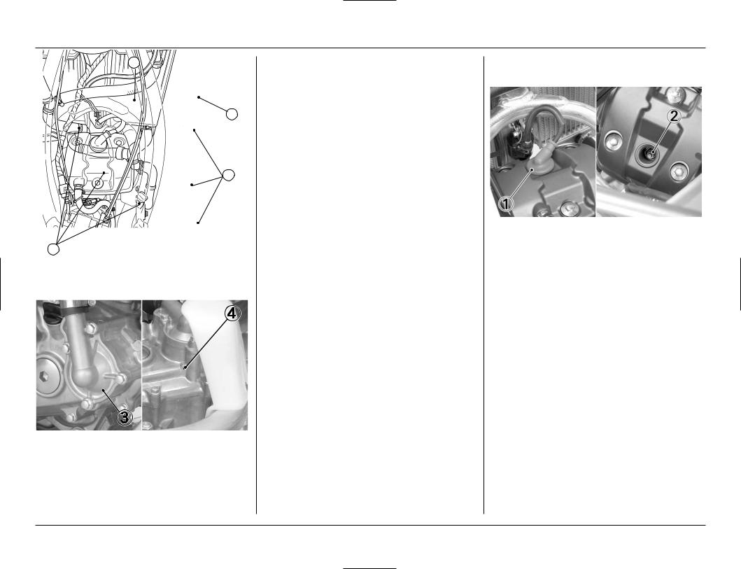
4.Remove the transmission oil filler cap and oil check bolt from the right crankcase cover. A small amount of oil should flow out of the oil check bolt hole. Allow any excess oil to flow out of the oil check bolt hole.
If no oil flows out of the oil check bolt hole, add oil slowly through the transmission oil filler hole until oil start to flow out of the oil check bolt hole.
Install the oil check bolt and transmission oil filler cap. Repeat step 1–4.
5.After inspection the oil level or adding oil, tighten the oil check bolt and transmission oil filler cap securely.
TORQUE:
Oil Check Bolt: 7 lbf ft (10 N m, 1.0 kgf m)
(1)TRANSMISSION OIL FILLER CAP
(2)OIL CHECK BOLT
Replacing Transmission Oil
1.Run the engine for three minutes, then shut if off.
2.Support the CRF in an upright position on a level surface.
3.Remove the transmission oil filler cap from the right crankcase cover
4.Place an oil drain pan under the engine to catch the oil. Then remove the transmission oil drain bolt and sealing washer.
5.After the oil has drained, install the transmission oil drain bolt with a new sealing washer.
TORQUE: 16 lbf ft (22 N m, 2.2 kgf m)
6.Fill the crankcase with recommended oil. capacity: 0.62 US qt (0.59 liter, 0.52 Imp qt)
at oil change
7.Check the transmission oil level by following the steps in Inspecting and Adding Transmission Oil (this page).
(1)TRANSMISSION OIL FILLER CAP
(2)TRANSMISSION OIL DRAIN BOLT
(3)SEALING WASHER
Recommended Transmission Oil
Use Pro Honda HP Trans Oil, Pro Honda GN4 or HP4 (without molybdenum additives) 4-stroke oil, or an equivalent.*
4-stroke oil performance
API |
SG or higher except oils labeled as |
classification |
energy conserving on the circular |
|
API service label |
|
|
viscosity |
SAE 10W-40 |
(weight) |
|
|
|
JASO T 903 |
MA |
|
|
others |
without friction modifiers as |
|
molybdenum additives |
|
|
*Suggested oils are equal in performance to SJ oils that are not labeled as energy conserving on the circular API service label.
•Your CRF does not need oil additives. Use recommended oil.
•Do not use oils with graphite or molybdenum additives. They may adversely affect clutch operation.
•Do not use API SH or higher oils displaying a circular API ”energy conserving” label on the container. They may affect lubrication and clutch performance.
NOT RECOMMENDED |
OK |
CAUTION:
•Oil is a major factor affecting the performance and service life of the transmission and clutch. Nondetergent, vegetable, or castor based racing oils are not recommended.
23
4. SERVICE AND MAINTENANCE
Other viscosities shown in the chart below may be used when the average temperature in your riding area is with in the indicated range.
JASO T 903 standard
The JASO T 903 standard is an index to choose engine oils for 4-stroke motorcycle engines.
There are two classes: MA and MB.
Oil conforming to the standard has the following classification on the oil container.
1
2
(1)CODE NUMBER OF THE SALES COMPANY OF THE OIL
(2)OIL CLASSIFICATION
COOLANT
Coolant Recommendation
Use Pro Honda HP coolant or an equivalent high quality ethylene glycol based anti-freeze containing corrosion protection inhibitors specifically recommended for use in aluminum engines (See anti-freeze container label).
CAUTION:
•Hard water or salt water is harmful to aluminum. The factory provides a 50/50 mix of anti-freeze and water in your CRF. This mixture is recommended for most operating temperatures and provides good corrosion protection. A higher concentration of antifreeze decreases the cooling system performance and is recommended only when additional protection against freezing is needed. Using less than 40% anti-freeze will not provide proper cooling or corrosion protection.
•Using coolant with silicate inhibitors may cause premature wear of water pump seals or blockage of radiator passages. Using tap water may cause engine damage.
Coolant Level
 WARNING
•Never remove the radiator cap when the engine is hot. The coolant is under pressure and severe scalding could result.
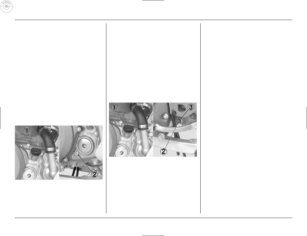
1.With the engine cold, remove the radiator cap and check coolant level. The coolant level is correct when it is at the bottom of the radiator filler neck.
(1) RADIATOR CAP
2. Add coolant up to the filler neck if the level is low.
NOTE :
•Inspect the coolant level before each outing. A coolant loss of 0.7 – 2.0 US oz (20 – 60 cm3, 0.7 – 2.1 Imp, oz) through the over flow tube is normal. If coolant loss is more than this, inspect the cooling system .
Capacity: 1.18 US qt (1.12 Iiter, 0.99 Imp qt) at disassembly
1.09 US qt (1.03 Iiter, 0.91 Imp qt) at coolant change
3. Install the radiator cap securely.
CAUTION:
•If the radiator cap is not installed properly, it will cause excessive coolant loss and may result in overheating and engine damage.
Cooling System Inspection
1.Check the cooling system for leaks (see the Honda Service Manual for troubleshooting of leaks).
2.Check water hoses for cracks, deterioration, and clamp bands for looseness.
3.Check the radiator mount for looseness.
4.Make sure the overflow tube is connected and not clogged.
5.Check the radiator fins for clogging.
6.Check the water leakage check hole below the water pump for leakage. Make sure the hole remains open. If water leaks through the check hole, the water pump seal is damaged. If oil leaks through the check hole, the transmission oil seal is damaged. See the Honda Service Manual or consult your authorized Honda dealer for replacing the water pump seal or the transmission oil seal. Both seals should be replaced at the same time.
24
2
1
2
2
(1)OVERFLOW TUBE
(2)WATER HOSE
(3)WATER PUMP COVER
(4)WATER LEAKAGE CHECK HOLE
SPARK PLUG
Standard:
(NGK) IFR8H11 (DENSO) VK24PRZ11
For extended high speed riding:
(NGK) IFR9H11 (DENSO) VK27PRZ11
If replacing with any other brand of spark plug, be certain to select the correct reach and heat range. Before removing the spark plug, clean the spark plug area thoroughly to prevent dirt from entering the cylinder.
CAUTION:
•The use of a spark plug of the incorrect reach or heat range can cause engine damage. The use of a non-resistor spark plug may cause ignition problems.
This motorcycle uses spark plug that have an iridium tip in center electrode and a platinum tip in side electrode .
Be sure to observe the following when servicing the spark plug.
•Do not clean the spark plug. If an electrode is contaminated with accumulated objects or dirt, replace the spark plug with a new one.
•Use only a “wire-type feeler gauge” to check the spark plug if necessary. To prevent damaging the iridium tip of the center electrode and platinum tip of the side electrode, never use a leaf-type feeler gauge.
1.Remove the fuel tank (page 17).
2.Disconnect the spark plug cap.
3.Remove the spark plug.
(1)SPARK PLUG CAP
(2)SPARK PLUG
4.Check the electrode for wear or deposits, the gasket for damage, and the insulator for cracks. Replace if you detect them.
5.Check the spark plug gap, using a wire-type feeler gauge. If the gap is out of specifications, replace the plug with a new one.
The recommended spark plug gap is: 0.039 – 0.043 in (1.0 – 1.1 mm)
(1)SPARK PLUG GAP
(2)SEALING GASKET
25
4. SERVICE AND MAINTENANCE
6.To obtain accurate spark plug readings, accelerate up to speed on a straightaway. Push the engine stop button and disengage the clutch by pulling the lever in.
Coast to a stop, then remove and inspect the spark plug. The porcelain insulator around the center electrode should appear tan or medium gray.
NOTE:
•If you're using a new plug, ride for at least ten minutes before taking a plug reading; a brand-new plug will not color initially.
If the electrodes appear burnt, or the insulator is white or light gray (lean) or the electrodes and insulator are black or fouled (rich), there is a problem elsewhere (page 70).
Check the carburetor, fuel system and ignition timing.
7.Install the spark plug by hand until finger tight, then tighten with a wrench until the sealing gasket is compressed ( 1/2 turn to compress a new spark plug gasket, 1/8 – 1/4 turn to compress a spark plug with a used gasket).
8.Connect the spark plug cap.
9.Install the fuel tank (page 18)
IGNITION
A CDI (Capacitive Discharge Ignition ) system is used on your CRF; consequently, routine ignition timing adjustment is unnecessary. If you want to check the ignition timing, refer to the Honda Service Manual.
ENGINE IDLE SPEED
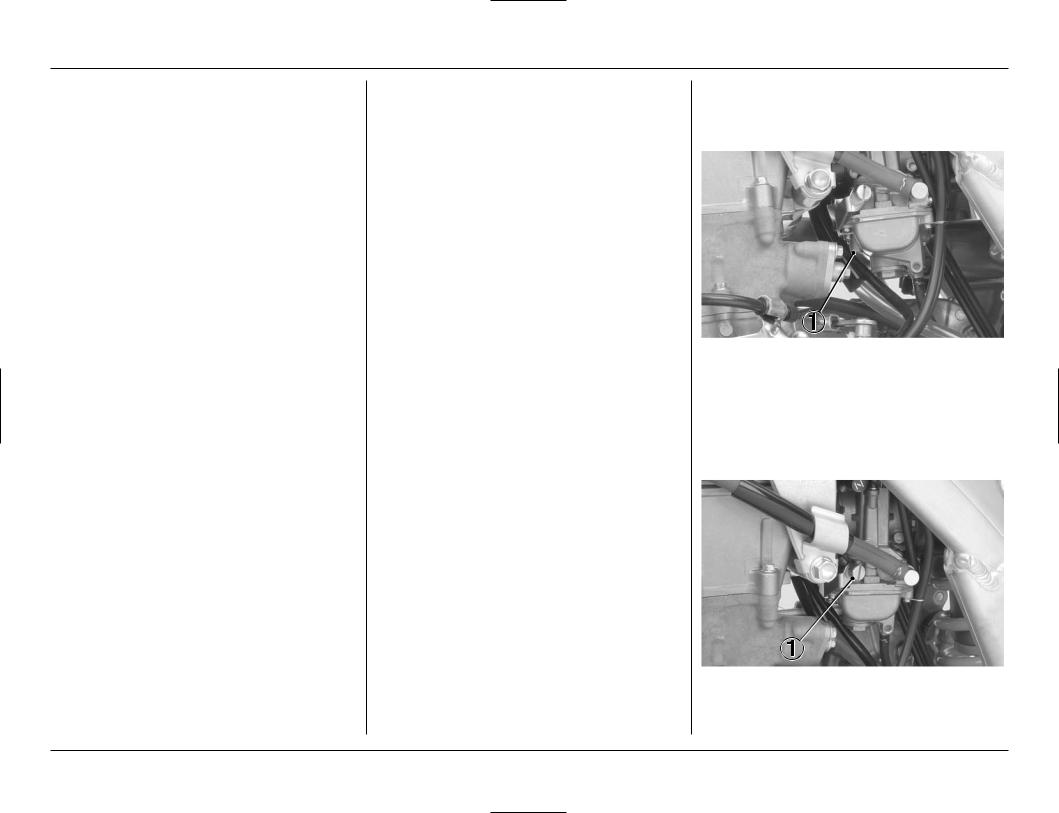
Adjustment Procedure
1.Turn the pilot screw in until it is lightly seated and record the number of turns. Turn the pilot screw out the same number of turns.
(1) PILOT SCREW
2.If the engine is cold, start it and warm it up 3 minutes. Then shut it off.
3.Connect a tachometer to the engine.
4.Shift into neutral. Start the engine.
5.Keep the motorcycle in an upright position.
6.Adjust idle speed with the throttle stop screw.
Idle speed:
1,700 ± 100 rpm
(1) THROTTLE STOP SCREW
26
CRANKCASE BREATHER
Service more frequently if your motorcycle is ridden in the rain or often at full throttle.
Service the breather if you can see deposits in the transparent section of the drain tube.
1.Remove the crankcase breather tube plug from the tube and drain deposits.
2.Reinstall the crankcase breather tube plug.
(1)CRANKCASE BREATHER TUBE PLUG
(2)TUBE
AIR CLEANER
The air cleaner uses polyurethane inner and outer pieces which cannot be separated.
A dirty air cleaner will reduce engine power.
To clean the air cleaner:
1.Remove the seat (page 17).
2.Loosen the air cleaner retaining bolt.
3.Align the two access top tabs of the air cleaner and ” ” mark of the air cleaner housing by rotating the air cleaner counterclockwise.
4 |
1 |
3
2
(1)AIR CLEANER
(2)AIR CLEANER RETAINING BOLT
(3)TWO ACCESS TOP TABS
(4)” ” MARK
4.Remove the air cleaner with the retaining bolt, keeping the two access top tabs up.
5. Remove the air cleaner from the air cleaner holder.
6 |
5 |
2 3
4
1
(1) AIR CLEANER HOLDER |
(2) AIR CLEANER |
(3)AIR CLEANER RETAINING BOLT
(4)HOLE
(5)HOLDER TAB (6) AIR CLEANER TAB
6.Wash the air cleaner in clean non-flammable cleaning solvent. Then wash in hot, soapy water, rinse well, and allow to dry thoroughly.
7.Clean the inside of the air cleaner housing.
 WARNING
•Never use gasoline or low flash point solvents for cleaning the air cleaner. A fire or explosion could result.
NOTE :
•The air cleaner is made in two pieces: inner and outer, which cannot be separated.
8.Allow the air cleaner to dry thoroughly. After drying, soak the air cleaner in clean Pro Honda Foam Filter Oil or an equivalent air cleaner oil.
Apply air cleaner oil to the entire surface, inner and outer, and rub it with both hands to saturate the air cleaner with oil. Squeeze out excess oil.
9.Apply a thin coat of white lithium grease to the sealing surface.
10.Assemble the air cleaner and holder.
Install the tab of the holder in the hole of the air cleaner tab, and the air cleaner retaining bolt through the assembly.
27

4. SERVICE AND MAINTENANCE
11.Install the assembly into the air cleaner housing keeping the two access top tabs up.
12.Carefully position the sealing flange of the element to prevent dirt intrusion.
13.Align the set tab of the air cleaner with the ” ” mark of the air cleaner housing by rotating the air cleaner clockwise. Tighten the retaining bolt securely.
CAUTION:
•If the air cleaner assembly is not installed correctly, dirt and dust may enter the engine resulting in rapid wear of the piston rings and cylinder.
5 |
3 |
2
|
1 |
|
4 |
(1) |
AIR CLEANER |
(2) |
SET TAB |
(3) |
” ” MARK |
(4) |
RETAINING BOLT |
(5) |
TWO ACCESS TOP TABS |
|
|
CLUTCH
Operation
1.Check for smooth clutch lever operation. Lubricate the clutch lever pivot or clutch cable if operation is not smooth.
2.Check the clutch cable for deterioration, kinks or damage.
Clutch Disc/Plate Removal
Drain the transmission oil (page 23).
Remove the rear brake pedal by removing its pivot bolt.
(1) REAR BRAKE PEDAL |
(2) PIVOT BOLT |
Remove the six clutch cover bolts and cover.
(1)CLUTCH COVER BOLTS
(2)CLUTCH COVER
Remove the six clutch spring bolts and clutch springs.
NOTE:
•Loosen the bolts in a crisscross pattern in 2 or 3 progressive steps.
Remove the clutch pressure plate.
(1)CLUTCH SPRING BOLT
(2)CLUTCH PRESSURE PLATE
Remove the clutch lifter and clutch lifter rod.
Remove the eight clutch discs and seven clutch plates.
NOTE:
•Turn the lifter bearing plate of the clutch lifter bearing with your finger. The bearing plate should turn smoothly and quietly. Discard the clutch lifter if the bearing plate does not turn smoothly.
(1) |
CLUTCH LIFTER |
(3) CLUTCH PLATES AND |
(2) |
CLUTCH LIFTER ROD |
DISCS |
28
 Loading...