


EU7000IS
Table of contents
 Loading...
Owner’s Manual
GENERATOR
EU7000is
See page 94 for instructions on assembling
your generator.
See page 99 for Initial Use Instructions.
C
2019 Honda Motor Co., Ltd. -All Rights Reserved
The engine exhaust from this product
contains chemicals known to the State
of California to cause cancer, birth
defects, or other reproductive harm.
Exhaust contains poisonous carbon
monoxide gas that can build up to
dangerous levels in closed areas.
Breathing carbon monoxide can
cause unconsciousness or death.
Never run the generator in a closed,
or even partly closed area where
people may be present.
Keep this owner’s manual handy, so that you can refer to it any time.
This owner’s manual is considered a permanent part of the generator
and should remain with the generator if resold.
The information and specifications included in this publication were in
effect at the time of approval for printing. Honda Motor Co., Ltd.
reserves the right, however, to discontinue or change specifications or
design at any time without notice and without incurring any obligation
whatsoever.

INTRODUCTION
Congratulations on your selection of a Honda generator. We are certain
you will be pleased with your purchase of one of the finest generators
on the market.
We want to help you get the best results from your new generator and
to operate it safely. This manual contains the information on how to do
that; please read it carefully.
As you read this manual, you will find information preceded by a
symbol. That information is intended to help you avoid damage
to your generator, other property, or the environment.
We suggest you read the Distributor’s Limited Warranty (see page 84)
to fully understand its coverage and your responsibilities of ownership.
When your generator needs scheduled maintenance, keep in mind that
your Honda servicing dealer is specially trained in servicing Honda
generators and is supported by the parts and service divisions of
American Honda. Your Honda servicing dealer is dedicated to your
satisfaction and will be pleased to answer your questions and
concerns.
Best Wishes,
Honda Motor Co., Ltd.
1
A FEW WORDS ABOUT SAFETY
Your safety and the safety of others are very important. And using this
generator safely is an important responsibility.
To help you make informed decisions about safety, we have provided
operating procedures and other information on labels and in this
manual. This information alerts you to potential hazards that could hurt
you or others.
Of course, it is not practical or possible to warn you about all the
hazards associated with operating or maintaining a generator. You
must use your own good judgment.
You will find important safety information in a variety of forms,
including:
• Safety Labels — on the generator.
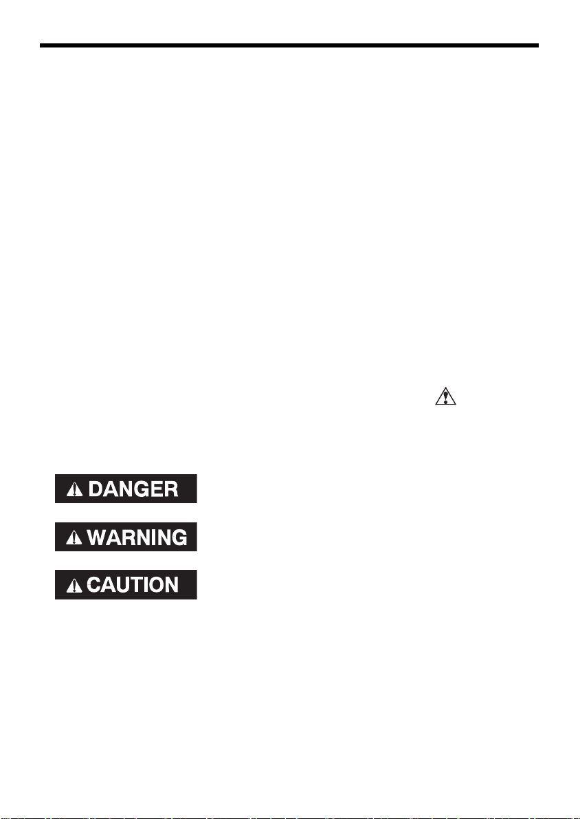
• Safety Messages — preceded by a safety alert symbol and one of
three signal words, DANGER, WARNING, or CAUTION.
These signal words mean:
You WILL be KILLED or SERIOUSLY HURT if
you don’t follow instructions.
You CAN be KILLED or SERIOUSLY HURT if
you don’t follow instructions.
You CAN be HURT if you don’t follow
instructions.
• Safety Headings — such as IMPORTANT SAFETY INFORMATION.
• Safety Section — such as GENERATOR SAFETY.
• Instructions — how to use this generator correctly and safely.
This entire book is filled with important safety information — please
read it carefully.
2

CONTENTS
GENERATOR SAFETY ...............................................................................6
IMPORTANT SAFETY INFORMATION .................................................6
Operator Responsibility.....................................................................6
Carbon Monoxide Hazards................................................................6
Electric Shock Hazards ......................................................................7
Fire and Burn Hazards .......................................................................7
Refuel With Care ................................................................................8
SAFETY LABEL LOCATIONS.................................................................9
CONTROLS & FEATURES.......................................................................10
COMPONENT & CONTROL LOCATIONS...........................................10
CONTROLS...........................................................................................12
MAIN Switch ....................................................................................12
ENGINE START Button....................................................................12
Starter Grip.......................................................................................13
Eco Throttle Switch..........................................................................13
Parallel Operation Outlets ...............................................................14
Voltage Selector Switch ..................................................................14
AC Circuit Protectors .......................................................................15
Ground Fault Circuit Interrupter (GFCI) Receptacle ......................16
Folding Handle .................................................................................17
Maintenance Covers ........................................................................18
FEATURES............................................................................................19
Ground Terminal..............................................................................19
OUTPUT Indicator............................................................................20
OVERLOAD ALARM (Indicator).......................................................20
OIL ALERT/CHECK Indicator............................................................21
i-Monitor ...........................................................................................22
Fuel Gauge .......................................................................................25
BEFORE OPERATION ..............................................................................26
ARE YOU READY TO GET STARTED?................................................26
Knowledge........................................................................................26
IS YOUR GENERATOR READY TO GO?.............................................26
Check the Engine .............................................................................27
Check the GFCI .................................................................................27
Battery Maintenance Cover.............................................................27
OPERATION .............................................................................................28
SAFE OPERATING PRECAUTIONS.....................................................28
STARTING THE ENGINE .....................................................................29
STOPPING THE ENGINE .....................................................................32
STARTING THE ENGINE with REMOTE CONTROL (Optional part) .... 33
STOPPING THE ENGINE with REMOTE CONTROL (Optional part) .... 34
3

CONTENTS
GFCI OPERATION CHECK ...................................................................35
AC OPERATION....................................................................................38
AC Applications................................................................................40
AC Receptacle Selection..................................................................41
Power Producing Circuits................................................................41
Voltage Selector Switch ..................................................................42
AC PARALLEL OPERATION.................................................................43
AC Parallel Operation Applications ................................................45
ECO THROTTLE SYSTEM....................................................................47
STANDBY POWER ...............................................................................48
Connections to a Building’s Electrical System ..............................48
System Ground ................................................................................48
Special Requirements......................................................................49
SERVICING YOUR GENERATOR............................................................50
THE IMPORTANCE OF MAINTENANCE.............................................50
MAINTENANCE SAFETY.....................................................................51
Safety Precautions ...........................................................................51
MAINTENANCE SCHEDULE ...............................................................52
REFUELING ..........................................................................................53
FUEL RECOMMENDATIONS...............................................................54
ENGINE OIL LEVEL CHECK .................................................................55
ENGINE OIL CHANGE..........................................................................56
ENGINE OIL RECOMMENDATIONS ...................................................57
AIR CLEANER SERVICE .......................................................................58
FOAM AIR FILTER CLEANING ............................................................59
SPARK PLUG SERVICE........................................................................60
SPARK ARRESTER SERVICE...............................................................62
BATTERY SERVICE ..............................................................................63
FUSE .....................................................................................................67
STORAGE.................................................................................................68
STORAGE PREPARATION...................................................................68
Cleaning............................................................................................68
Fuel....................................................................................................68
Engine Oil .........................................................................................71
Engine Cylinder................................................................................71
Battery...............................................................................................71
STORAGE PRECAUTIONS ..................................................................72
REMOVAL FROM STORAGE...............................................................72
TRANSPORTING......................................................................................73
4

CONTENTS
TAKING CARE OF UNEXPECTED PROBLEMS ......................................74
ENGINE WILL NOT START..................................................................74
ENGINE LACKS POWER......................................................................75
NO POWER AT THE AC RECEPTACLES.............................................75
TECHNICAL INFORMATION ...................................................................76
Serial Number Location ..................................................................76
Emission Control System Information...........................................77
Air Index ...........................................................................................79
Specifications ...................................................................................80
Wiring Diagram................................................................................81
CONSUMER INFORMATION ..................................................................82
Dealer Locator Information .............................................................82
Honda Publications..........................................................................82
Customer Service Information........................................................83
Distributor’s Limited Warranty .......................................................84
Emission Control System Warranty ...............................................89
ASSEMBLY ..............................................................................................94
SAFETY.................................................................................................94
The Importance of Proper Assembly .............................................94
Important Safety Precautions .........................................................95
ASSEMBLY...........................................................................................96
Unpacking.........................................................................................96
Loose Parts .......................................................................................96
Wheel Kit Installation.......................................................................97
Battery...............................................................................................98
INITIAL USE INSTRUCTIONS .................................................................99
ENGINE OIL..........................................................................................99
FUEL....................................................................................................100
BATTERY VOLTAGE ..........................................................................102
BEFORE OPERATION.........................................................................102
REGISTRATION..................................................................................102
OPTIONAL PARTS .................................................................................103
REMOTE CONTROL KIT ....................................................................103
HANGER KIT.......................................................................................105
INDEX .....................................................................................................106
QUICK REFERENCE INFORMATION ............................ Inside back cover
5

GENERATOR SAFETY
IMPORTANT SAFETY INFORMATION
Honda generators are designed for use with electrical equipment that has
suitable power requirements. Other uses can result in injury to the operator or
damage to the generator and other property.
Most injuries or property damage can be prevented if you follow all of the
instructions in this manual and on the generator. The most common hazards
are discussed below, along with the best way to protect yourself and others.
Operator Responsibility
• Know how to stop the generator quickly in case of emergency.
• Understand the use of all generator controls, output receptacles, and
connections.
• Be sure that anyone who operates the generator receives proper instruction.
Do not let children operate the generator without parental supervision.
Carbon Monoxide Hazards
A generator's exhaust contains toxic carbon monoxide, which you
cannot see or smell. Breathing carbon monoxide can KILL YOU IN
MINUTES. To avoid carbon monoxide poisoning, follow these
instructions when operating a generator:
• Only run a generator OUTSIDE, far away from windows, doors, and vents.
• Never operate a generator inside a house, garage, basement, crawl
space, or any enclosed or partially enclosed space.
• Never operate a generator near open doors or windows.
• Get fresh air and seek medical attention immediately if you suspect
you have inhaled carbon monoxide.
Early symptoms of carbon monoxide exposure include headache,
fatigue, shortness of breath, nausea, and dizziness. Continued
exposure to carbon monoxide can cause loss of muscular coordination,
loss of consciousness, and then death.
To alert you to potentially dangerous levels of carbon monoxide coming
from a generator operating outside or from other sources, install battery
operated carbon monoxide alarms or plug-in carbon monoxide alarms
with battery back-up on every level of the home and outside sleeping
areas, according to the manufacturer’s instructions.
6

GENERATOR SAFETY
Electric Shock Hazards
• The generator produces enough electric power to cause a serious
shock or electrocution if misused.
• Using a generator or electrical appliance in wet conditions, such as
rain or snow, or near a pool or sprinkler system, or when your hands
are wet, could result in electrocution. Keep the generator dry.
• If the generator is stored outdoors, unprotected from the weather,
check the Ground Fault Circuit Interrupter (GFCI) receptacle and all
other electrical components on the control panel before each use.
Moisture or ice can cause a malfunction or short circuit in electrical
components that could result in electrocution.
• Do not connect to a building’s electrical system unless an isolation
switch has been installed by a qualified electrician.
• For parallel operation, use only a Honda approved parallel kit (optional
equipment) when connecting one EU7000is to another EU7000is
generator.
• Never connect different generator models.
Fire and Burn Hazards
• The exhaust system gets hot enough to ignite some materials.
– Keep the generator at least 3 feet (1 meter) away from buildings
and other equipment during operation.
– Do not enclose the generator in any structure.
– Keep flammable materials away from the generator.
• The muffler becomes very hot during operation and remains hot for
a while after stopping the engine. Be careful not to touch the muffler
while it is hot. Let the engine cool before storing the generator
indoors.
7

GENERATOR SAFETY
Refuel With Care
Gasoline is extremely flammable, and gasoline vapor can explode.
Do not refuel during operation.
Allow the engine to cool if it has been in operation.
Refuel only outdoors in a well-ventilated area and on a level surface.
Never smoke near gasoline, and keep other flames and sparks away.
Do not overfill the fuel tank.
Make sure that any spilled fuel has been wiped up and cleaned before
starting the engine.
Always store gasoline in an approved container.
8
GENERATOR SAFETY
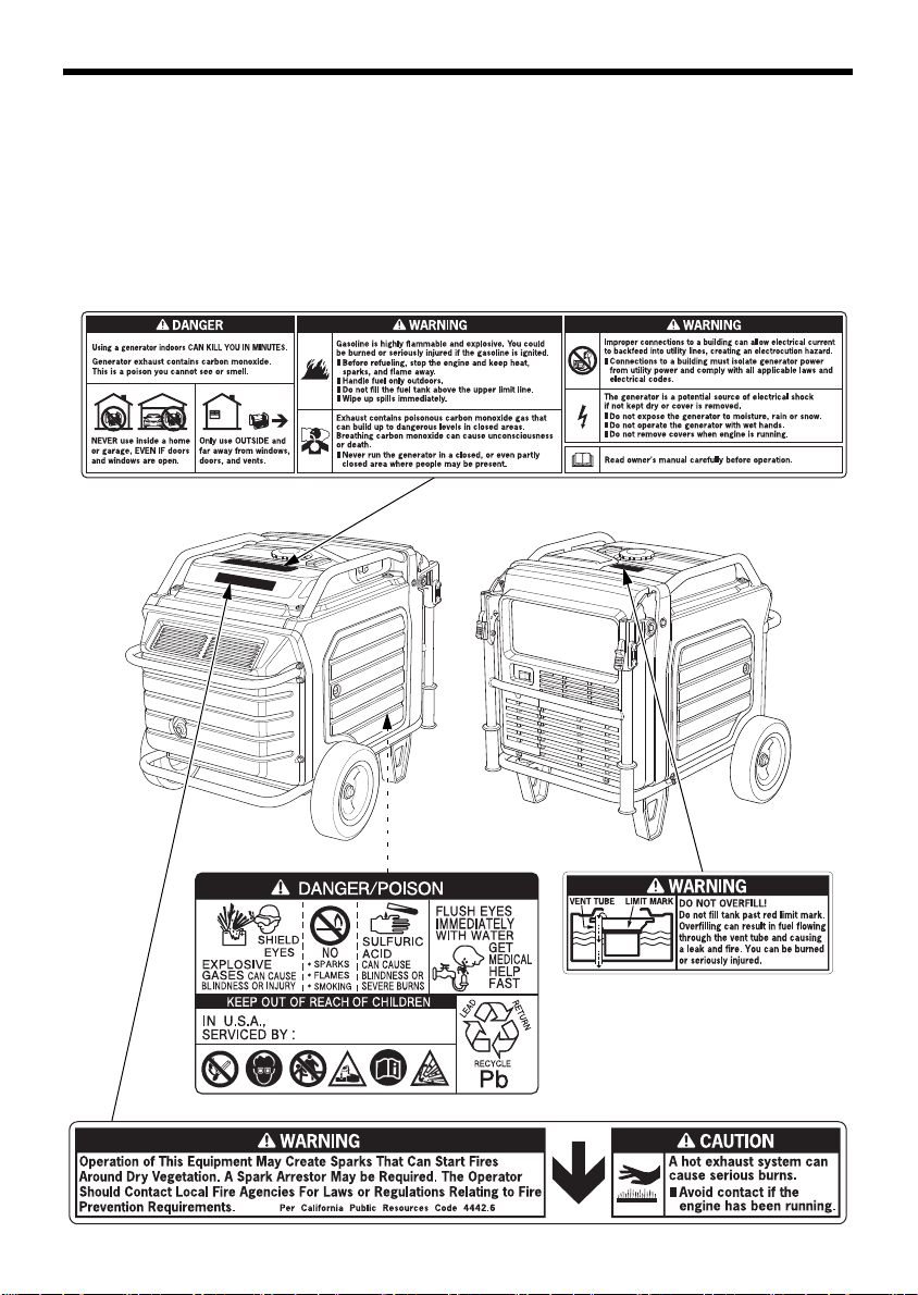
SAFETY LABEL LOCATIONS
These labels warn you of potential hazards that can cause serious
injury. Read them carefully. If a label comes off or becomes hard to
read, contact your Honda servicing dealer for a replacement.
9

CONTROLS & FEATURES
OVERLOAD
INDICATOR
OIL ALERT/
CHECK INDICATOR
i-MONITOR
BUTTON
ECO THROTTLE SWITCH
AC CIRCUIT PROTECTORS
RECEPTACLES
OUTPUT INDICATOR
i-MONITOR
ENGINE START
BUTTON
VOLTAGE SELECTOR SWITCH
MAIN SWITCH
PARALLEL OPERATION OUTLETS
GFCI RECEPTACLES
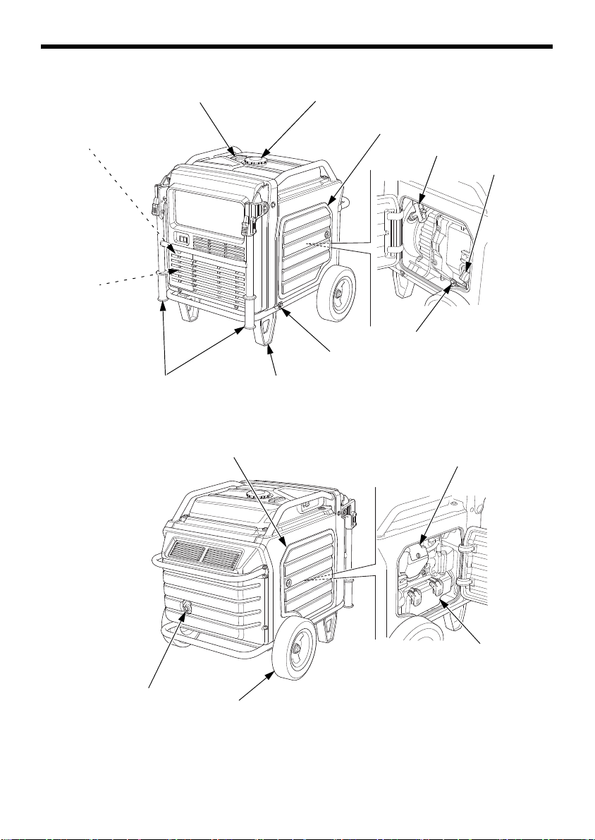
COMPONENT & CONTROL LOCATIONS
Use the illustrations on these pages to locate and identify the most
frequently used controls.
10
CONTROL & FEATURES
FUEL GAUGE
RIGHT MAINTENANCE COVER
OIL DRAIN PLUG
MUFFLER TIP
FUEL TANK CAP
STARTER GRIP
OIL FILLER CAP
GROUND TERMINAL
STANDHANDLE
BATTERY
(inside battery
maintenance cover)
FUSE
(inside battery
maintenance cover)
WHEEL
LEFT MAINTENANCE COVER
AIR CLEANER
SPARK PLUG
INSPECTION COVER
11
CONTROL & FEATURES
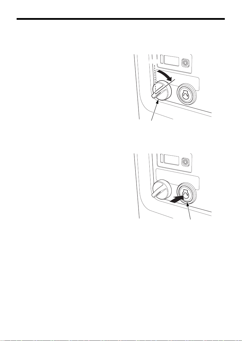
MAIN SWITCH
ON
OFF
ENGINE START BUTTON
CONTROLS
MAIN Switch
The MAIN switch controls the
ignition system.
OFF – Stops the engine. The main
switch key can be removed/
inserted.
ON – Running position, and for
starting with the ENGINE START
button or recoil starter, and for
using the remote control kit
(optional parts).
ENGINE START Button
With the MAIN switch in the ON
position, press and release the
ENGINE START button to start the
engine.
12
Starter Grip
STARTER GRIP
20°
ECO THROTTLE SWITCH
OFF
ON
Used when the battery voltage is
too low to turn the starter motor.
Pulling the starter grip operates
the recoil starter to start the
engine.
• Do not exceed 20 degrees from
horizontal when pulling the
starter grip.
• Do not allow the starter grip to
snap back against the engine.
Return it gently to prevent
damage to the starter.
• Do not let the starter rope rub
against the generator body, or
the rope will wear out
prematurely.
CONTROL & FEATURES
Eco Throttle
®
Switch
The Eco Throttle system automatically reduces engine speed when all
loads are turned off or disconnected. When appliances are turned on or
reconnected, the engine returns to the proper speed to power the
electrical load.
If high electrical loads are connected simultaneously, turn the
Eco Throttle switch to the OFF position to reduce voltage changes.
ON – Recommended to minimize
fuel consumption and further
reduce noise levels when a
reduced load or no load is applied
to the generator.
OFF – The Eco Throttle system
does not operate. Generator
operates at full speed.
13
CONTROL & FEATURES
PARALLEL OPERATION OUTLETS
120 V/240 V
VOLTAGE SELECTOR SWITCH
120 V ONLY
Parallel Operation Outlets
These outlets are used for connecting the EU7000is to another
EU7000is generator for parallel operation (see page 43). A Honda
approved parallel kit (optional equipment) is required for parallel
operation. This kit can be purchased from an authorized Honda
generator dealer.
Voltage Selector Switch
Select the voltage before starting the engine.
Always disconnect or turn OFF all appliances or tools connected to the
generator before changing the voltage selector switch position.
The voltage selector switch changes generator output to produce
‘‘120 V ONLY’’ or ‘‘120 V/240 V’’. If a 240 V appliance is connected to
the 4-prong receptacle, the switch must be in the ‘‘120 V/240 V’’
position. If only the 120 V 3-prong receptacles are being used, select
the ‘‘120 V ONLY’’ position.
Switch Position
120 V/240 V: The 120 V and 120 V/240 V receptacles can be used
simultaneously.
120 V ONLY: ONLY the 120 V receptacles can be used. Do not use the
120 V/240 V receptacle in this position. The most power will be
available at the 30 A 120 V locking plug receptacle.
14
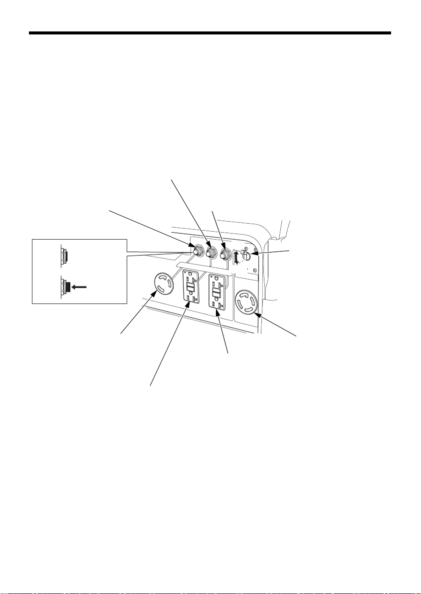
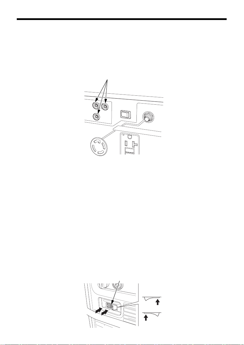
CONTROL & FEATURES
➃ 120 V/240 V 30 A
AC CIRCUIT PROTECTOR
for Receptacle
➂
OFF
ON
AC CIRCUIT PROTECTOR
for Receptacle
➃
PUSH
➂ GFCI RECEPTACLE
(120 V 20 A DUPLEX RECEPTACLE)
➁ GFCI RECEPTACLE
(120 V 20 A DUPLEX RECEPTACLE)
➀ 120 V 30 A
AC CIRCUIT PROTECTOR
for Receptacle
➀
AC CIRCUIT PROTECTOR
for Receptacle
➁
ON
OFF
AC Circuit Protectors
The AC circuit protectors will automatically switch OFF if there is a
short circuit or a significant overload of the generator at each
receptacle. If an AC circuit protector switches OFF automatically,
check that the appliance is working properly and does not exceed the
rated load capacity of the circuit before resetting the AC circuit
protector ON.
15
CONTROL & FEATURES
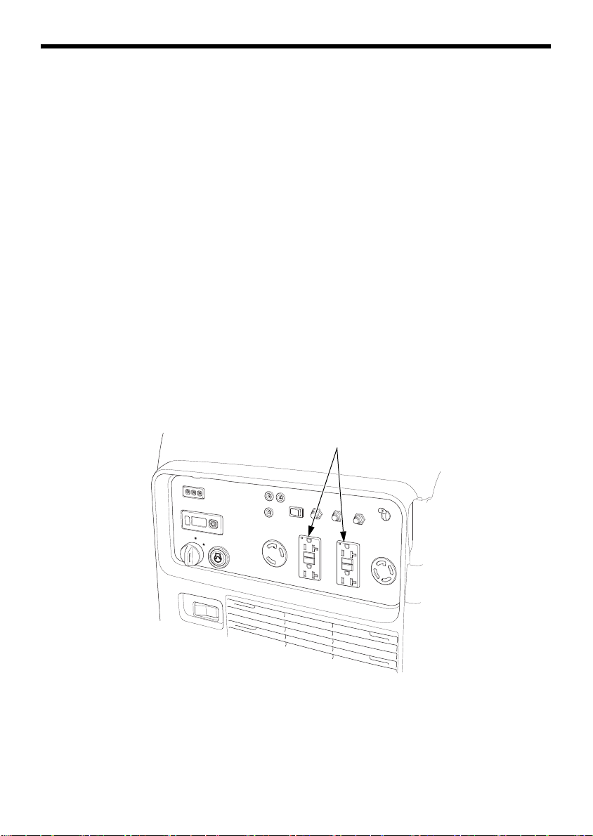
GFCI RECEPTACLES
(120 V 20 A DUPLEX RECEPTACLES)
Ground Fault Circuit Interrupter (GFCI) Receptacle
Each 120 V 20 A duplex receptacle is protected by a Ground Fault
Circuit Interrupter (GFCI) for protection against the shock hazard of
ground fault currents.
An example of ground fault current is the current that would flow
through a person who is using an appliance with faulty insulation and,
at the same time, is in contact with an electrical ground such as a
plumbing fixture, wet floor, or earth. The GFCI will protect against
current flowing through that person.
The GFCI will not protect against short circuit or overloads.
GFCIs can be expected to interrupt power supply if there are ground
faults or stray current imposed on the wiring by other electrical
devices, wiring, or equipment. Due to the risk of a power interruption,
this generator is not recommended for powering medical or life
support equipment.
16
CONTROL & FEATURES
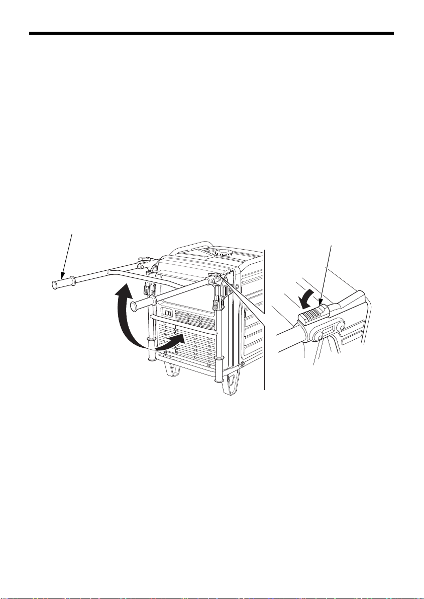
HANDLE
Handle in
pushing
position
Handle in
stationary
position
HANDLE LOCK LEVER
Folding Handle
The foldable handle makes the generator easy to push and should be
folded when the generator is stationary. Do not rest objects on the
extended handle.
To Extend The Handle
Lift handle upward. Lock levers will lock and secure the handle into
place.
To Fold The Handle
1. Press both handle lock levers downward.
2. Lower the handle.
17
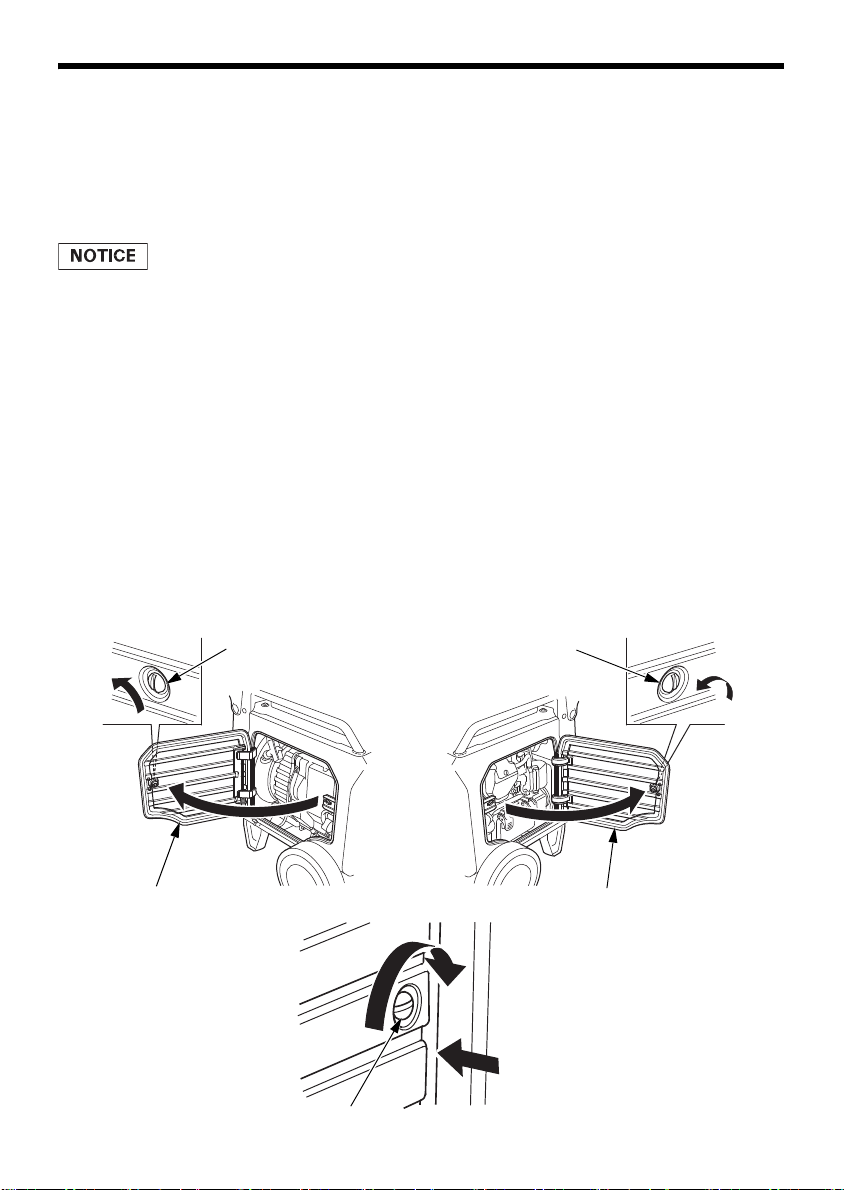
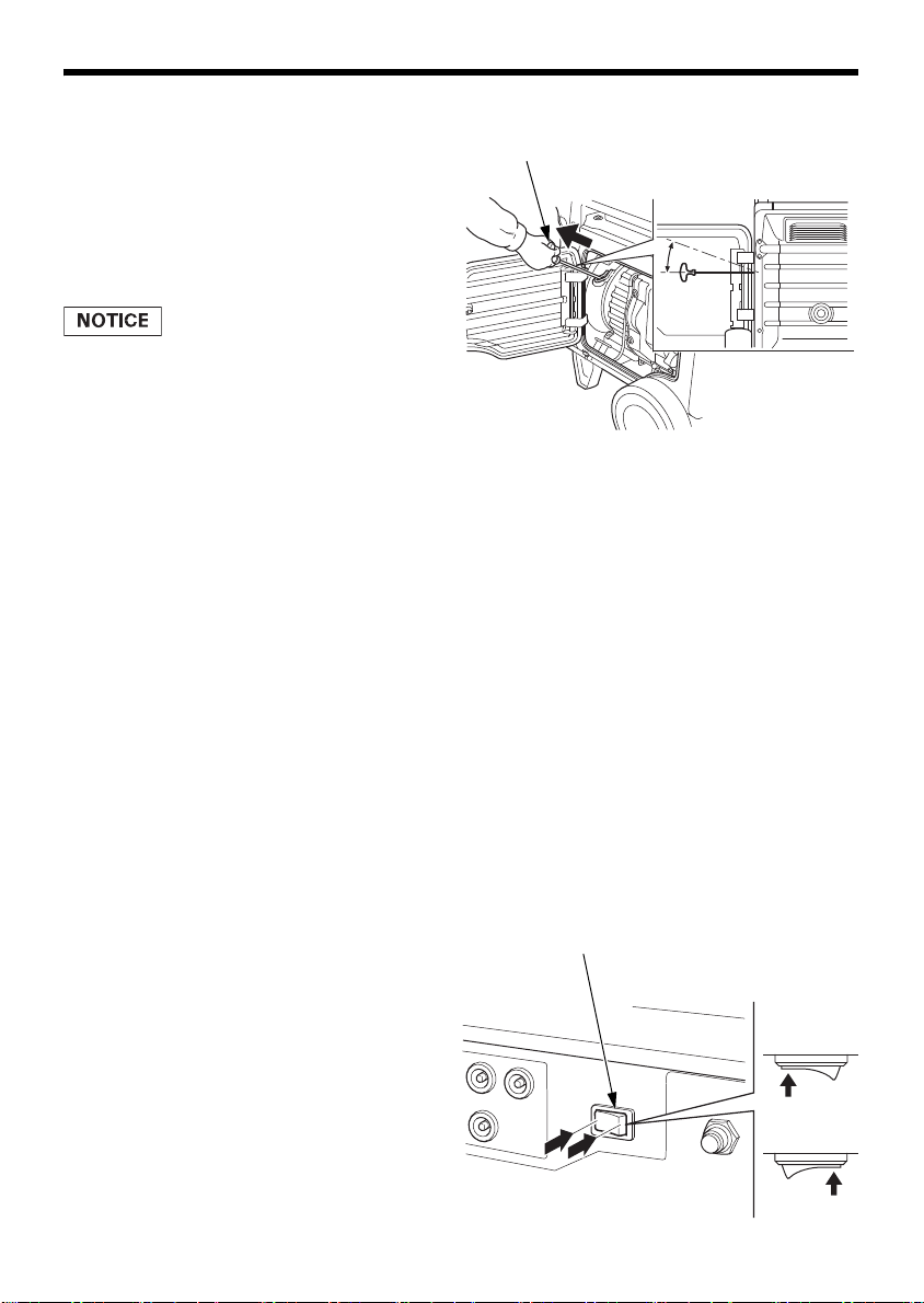
CONTROL & FEATURES
LATCH LATCH
LEFT MAINTENANCE COVER
LATCH
RIGHT MAINTENANCE COVER
Push the cover closed and turn
the latch.
Maintenance Covers
Open and close the maintenance cover for maintenance of the
EU7000is.
Open the right maintenance cover, to use the recoil starter when the
battery is discharged. Be sure the maintenance cover is closed while
the generator is running.
Running the generator with maintenance cover(s) open will adversely
affect the engine performance, and will cause the generator to overheat.
Open the right maintenance cover for:
• Engine oil inspection/replacement
• Recoil starter
Open the left maintenance cover for:
• Spark plug inspection/replacement
• Air cleaner inspection/cleaning
To open:
Turn the latch 90° counterclockwise to unlock and open the
maintenance cover.
To close:
Turn the latch 90° clockwise to lock while pushing the cover.
18

CONTROL & FEATURES
GROUND TERMINAL
FEATURES
Ground Terminal
The ground terminal is connected to the frame of the generator, the
metal non-current-carrying parts of the generator, and the ground
terminals of each receptacle.
Before using the ground terminal, consult a qualified electrician,
electrical inspector, or local agency having jurisdiction for local codes
or ordinances that apply to the intended use of the generator.
NEUTRAL FLOATING:
• The generator (stator winding) is isolated from the frame and from
the AC receptacle ground pin.
• Electrical devices that require a grounded receptacle pin connection
will not function if the receptacle ground pin is not functional.
19
CONTROL & FEATURES
OUTPUT INDICATOR (GREEN)
OVERLOAD INDICATOR (RED)
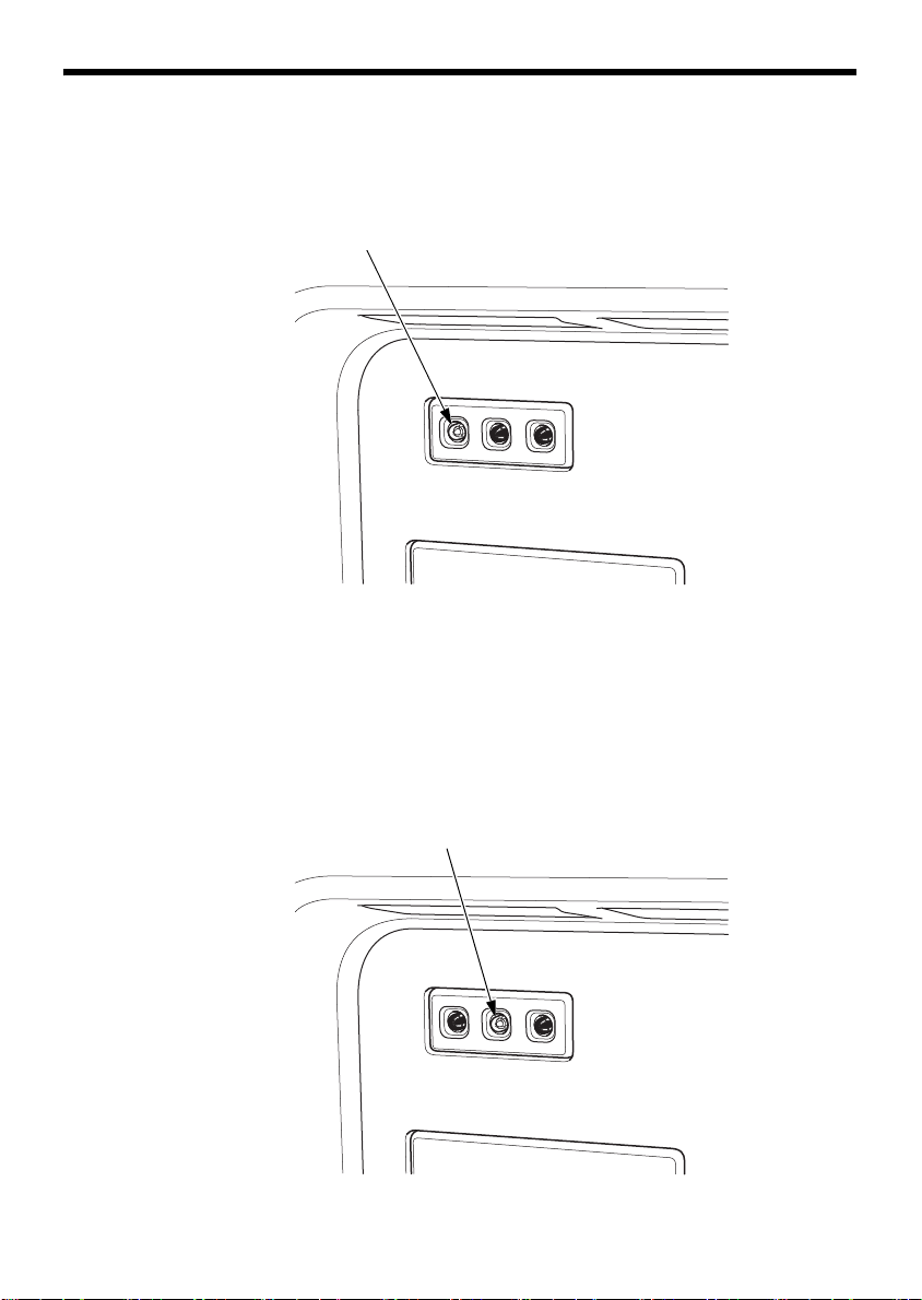
OUTPUT Indicator
The green OUTPUT indicator is illuminated when the generator is
operating normally. It indicates that the generator is producing
electrical power at the receptacles.
OVERLOAD ALARM (Indicator)
If the generator is overloaded, or if there is a short circuit in a
connected appliance, or if the inverter is overheated, the red
OVERLOAD indicator will come ON. When the generator is operating
overloaded, the red OVERLOAD indicator will stay ON and, after about
five seconds, current to the connected appliance(s) will shut off, and
the green OUTPUT indicator will go OFF.
20
CONTROL & FEATURES
OIL ALERT/CHECK INDICATOR (RED)
It blinks.
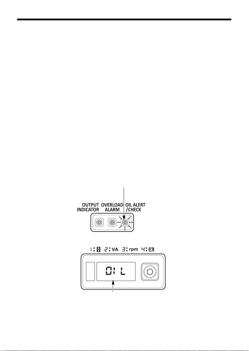
OIL ALERT®/CHECK Indicator
The Oil Alert system is designed to prevent engine damage caused by
an insufficient amount of oil in the crankcase. Before the oil level in the
crankcase can fall below a safe limit, the OIL ALERT/CHECK indicator
comes ON, and the Oil Alert system will automatically stop the engine
(the MAIN switch will remain in the ON position).
The i-Monitor display will show ‘‘OIL’’ on the screen and the OIL
ALERT/CHECK indicator will illuminate.
If the engine stops or the OIL ALERT/CHECK indicator comes ON when
you press the ENGINE START button or pull the starter grip, check the
engine oil level (see page 55) before troubleshooting in other areas.
Even when oil is added to the engine, the generator will not restart until
the OIL ALERT/CHECK indicator is reset. To reset the OIL ALERT/
CHECK indicator, turn the MAIN switch to the OFF position, add the
proper amount of oil (see page 55), and then turn the MAIN switch
back to the ON position.
If the OIL ALERT/CHECK indicator blinks, consult an authorized Honda
generator dealer.
21
CONTROL & FEATURES
SINGLE-DIGIT
SCREEN DISPLAY
i-MONITOR BUTTON
FOUR-DIGIT
SCREEN DISPLAY
i-Monitor™
The i-Monitor is a user interface that allows the operator to view (when
the generator is running) total operating time in hours, generator
output, engine RPM, battery voltage, and error messages. The different
display modes are selected by pressing the i-Monitor button.
i-Monitor at Startup
During start up, the i-Monitor display and all three indicators will
simultaneously blink once. The condition of the i-Monitor display and all
three indicators can be checked. Once the generator is running, the
green OUTPUT indicator and the i-Monitor display will remain lit.
Display Backlight Flashes
If the key is left in the ON position for over 30 seconds without starting
the engine, the display will start to flash.
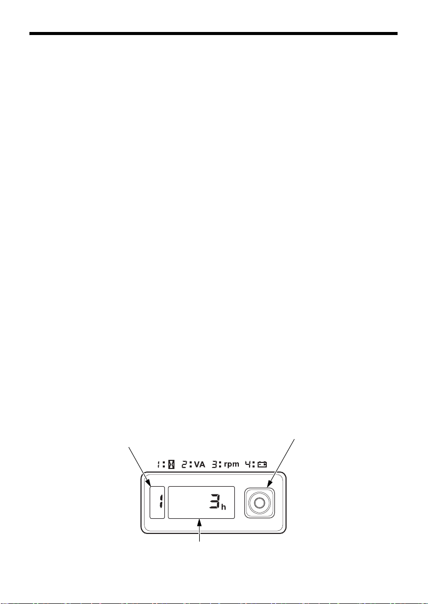
i-Monitor Display
The i-Monitor display is divided into two screens. The single-digit
screen displays the i-Monitor mode, which is represented by a number
1 through 4. The four-digit screen displays the four mode values or any
activated error messages.
i-Monitor Display Mode 1 – Total Operating Hours
This mode displays the total operating hours of the generator. When
the generator is running, the total operating time accumulates. If the
total operating time is less than one hour, the numeric display will be
‘‘0.’’ When the operating time is one hour or greater, the display will be
‘‘1’’ or ‘‘2’’ and so on. Base the generator’s maintenance schedule on
the accumulated time displayed.
22
CONTROL & FEATURES
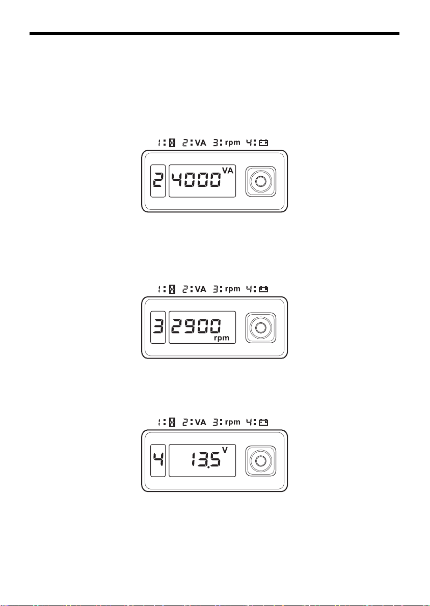
i-Monitor Display Mode 2 – Power Output
This mode displays an approximate generator output on the display
screen. The output is expressed in VA (volt-amperes). The output value
is not an exact measurement and should be regarded as a reference
only. Power output will not display until a load is connected to the
generator.
i-Monitor Display Mode 3 – Engine RPM
When the i-Monitor is in this mode, the engine’s speed, expressed in
revolutions-per-minute (RPM), is displayed.
i-Monitor Display Mode 4 – Battery Voltage
This mode displays the battery condition, expressed in Volts DC.
23

CONTROL & FEATURES
OIL ALERT/CHECK INDICATOR
ERROR MESSAGE
(Example: E-01)
i-Monitor Low Battery Message
If the ENGINE START button is pressed and ‘‘batt’’ is shown on the iMonitor display, the battery voltage is too low to operate the engine’s
electric starter. Use the recoil starter to start the generator. Have the
battery recharged and checked (see page 66).
i-Monitor System Error Messages
If the generator has a system malfunction, it will show an error
message on the i-Monitor display. During remote control operation, an
E-01 error message may display if the ENGINE START button is
pressed for more than 10 seconds. With an E-01 error message, the
engine will stay running and the electrical output may stay constant.
Normal remote control operation will be restored after the E-01 error
message clears automatically. If the E-01 error message does not clear
automatically or if any other error message displays, contact an
authorized Honda generator dealer.
24
CONTROL & FEATURES
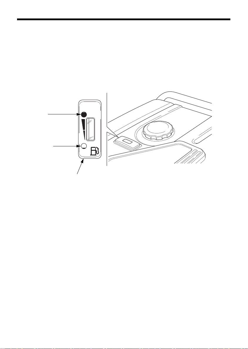
FULL
FUEL GAUGE
EMPTY
Fuel Gauge
The fuel gauge is a mechanical device that measures the fuel level in
the tank. The red indicator in the window will reference the level in
relation to full or empty. To provide increased operating time, start with
a full tank before operation. Check the fuel level with the generator on
a level surface. Always refuel with the engine OFF and cool.
25

BEFORE OPERATION
ARE YOU READY TO GET STARTED?
Your safety is your responsibility. A little time spent in preparation will
significantly reduce your risk of injury.
Knowledge
Read and understand this manual. Know what the controls do and how
to operate them.
Familiarize yourself with the generator and its operation before you begin
using it. Know how to quickly shut off the generator in case of an emergency.
If the generator is being used to power appliances, be sure that they do
not exceed the generator’s load rating (see page 40).
IS YOUR GENERATOR READY TO GO?
For your safety, to ensure compliance with environmental regulations,
and to maximize the service life of your equipment, it is very important
to take a few moments before you operate the generator to check its
condition. Be sure to take care of any problem you find, or have your
servicing dealer correct it, before you operate the generator.
Failure to properly maintain this
generator, or failing to correct a
problem before operation, could
result in a significant malfunction.
Some malfunctions can cause
serious injuries or death.
Always perform a pre-operation
inspection before each operation
and correct any problems.
To prevent a possible fire, keep the generator at least 3 feet (1 meter)
away from building walls and other equipment during operation. Do not
place flammable objects close to the engine.
Before beginning your pre-operation checks, be sure the generator is on
a level and firm surface and the MAIN switch is in the OFF position.
26
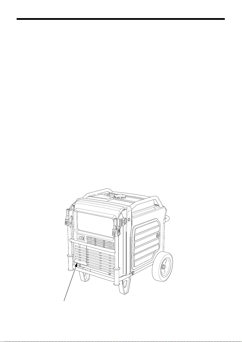
BEFORE OPERATION
BATTERY MAINTENANCE COVER
Check the Engine
• Before each use, look around and underneath the engine for signs of
oil or gasoline leaks.
• Check the engine oil level (see page 55). A low engine oil level will
cause the Oil Alert system to shut down the engine.
• Check the air filters (see page 58). Dirty air filters will restrict air flow
to the fuel system, reducing engine and generator performance.
• Check the fuel level (see page 53). Starting with a full tank will help
to eliminate or reduce operating interruptions for refueling.
Check the GFCI
Check the GFCI operation (see page 35) after starting the engine.
Battery Maintenance Cover
Never operate the generator without the battery maintenance cover in
place, as poor engine and generator performance will result.
27

OPERATION
SAFE OPERATING PRECAUTIONS
Before operating the generator for the first time, review chapters
GENERATOR SAFETY (see page 6) and BEFORE OPERATION (see page
26).
For your safety, do not operate the generator in an enclosed area such
as a garage. Your generator’s exhaust contains poisonous carbon
monoxide gas that can collect rapidly in an enclosed area and cause
illness or death.
Exhaust contains poisonous carbon
monoxide gas that can build up to
dangerous levels in closed areas.
Breathing carbon monoxide can
cause unconsciousness or death.
Never run this product's engine in a
closed, or even partly closed area
where people may be present.
Before connecting an AC appliance or power cord to the generator:
• Use grounded 3-prong extension cords, tools, and appliances, or
double-insulated tools and appliances.
• Inspect cords and plugs, and replace if damaged.
• Do not use cord lengths greater than 164 feet (50 meters), and do
not use multiple tools and appliances with built-in noise filters. Such
use may activate the GFCI.
• Make sure that the appliance is in good working order. Faulty
appliances or power cords can create a potential for electric shock.
• Make sure the electrical rating of the tool or appliance does not
exceed the rated power of the generator or the receptacle being used.
• Operate the generator at least 3 feet (1 meter) away from buildings
and other equipment.
• Do not operate the generator in an enclosed structure.
• Do not place flammable objects close to the engine or locate the
generator near flammable materials.
28
Loading...