


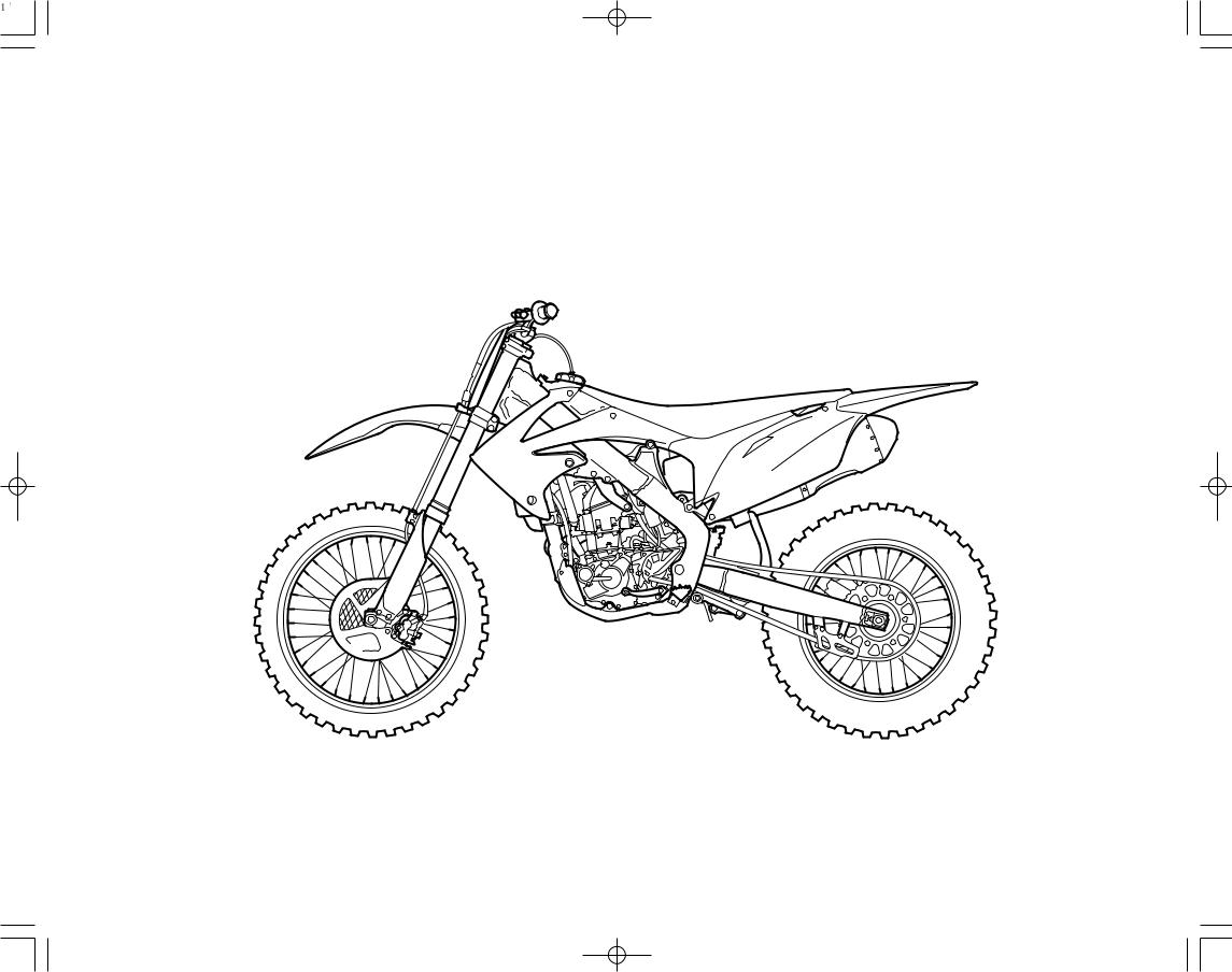
2012
Honda CRF250R
OWNER’S MANUAL & COMPETITION HANDBOOK
Introduction
Congratulations on choosing your Honda CRF motocross motorcycle.
When you own a Honda, you’re part of a worldwide family of satisfied customers – people who appreciate Honda’s reputation for building quality into every product.
Your CRF is a high performance racing motorcycle that utilizes the latest motocross technology and is intended for competition use in sanctioned, closed-course events by experienced riders only.
Be aware that motocross is a physically demanding sport that requires more than just a fine motorcycle. To do well, you must be in excellent physical condition and be a skillful rider. For the best results, work diligently on your physical conditioning and practice frequently.
Before riding, take time to get acquainted with your CRF and how it works. To protect your investment, we urge you to take responsibility for keeping your CRF well maintained. Scheduled service is a must, of course. But it’s just as important to observe the break-in guidelines, and perform all the pre-ride and other periodic checks detailed in this manual.
You should also read the owner’s manual before you ride. It’s full of facts, instructions, safety information, and helpful tips. To make it easy to use, the manual contains a table of contents, a detailed list of topics at the beginning of each section, and an index at the back of the book.
As you read this manual, you will find information that is preceded by a NOTICE symbol. This information is intended to help you avoid damage to your CRF, other property, or the environment.
Unless you are mechanically qualified and have the proper tools, you should see your dealer for the service and adjustment procedures discussed in this manual.
An official Honda Service Manual for your CRF is available (page 160). It is the same manual your dealer uses. If you plan to do any service on your CRF beyond the standard maintenance procedures in this manual, you will find an official Honda Service Manual a valuable reference.
If you have any questions, or if you ever need a special service or repairs, remember that your dealer knows your CRF best and is dedicated to your complete satisfaction.
Please report any change of address or ownership to your dealer so we will be able to contact you concerning important product information.
You may also want to visit our website at USA: www.powersports.honda.com. Canada: www.honda.ca.
Happy riding!
California Proposition 65 Warning
WARNING: This product contains or emits chemicals known to the State of California to cause cancer and birth defects or other reproductive harm.
ABBREVIATION
Throughout this manual, the following abbreviations are used to identify the respective parts or system.
Abbrev. term |
Full term |
|
|
|
|
CKP sensor |
Crankshaft Position sensor |
|
|
DTC |
Diagnostic Trouble Code |
|
|
ECM |
Engine Control Module |
|
|
ECT sensor |
Engine Coolant Temperature sensor |
|
|
HPSD |
Honda Progressive Steering Damper |
|
|
IAT sensor |
Intake Air Temperature sensor |
|
|
MAP sensor |
Manifold Absolute Pressure sensor |
|
|
MIL |
Malfunction Indicator Lamp |
|
|
PGM-FI |
Programmed Fuel Injection |
|
|
TDC |
Top Dead Center |
|
|
TP sensor |
Throttle Position sensor |
|
|
Introduction

A Few Words About Safety
Your safety, and the safety of others, is very important. And operating this motorcycle safely is an important responsibility.
To help you make informed decisions about safety, this manual contains a section devoted to Motorcycle Safety, as well as a number of Safety Messages throughout the manual.
Safety Messages are preceded by a safety alert symbol  and one of three signal words: DANGER, WARNING, or CAUTION. These signal words mean:
 DANGER
 WARNING
 CAUTION
You WILL be KILLED or SERIOUSLY HURT if you don’t follow instructions.
You CAN be KILLED or SERIOUSLY HURT if you don’t follow instructions.
You CAN be HURT if you don’t follow instructions.
Of course, it is not practical or possible to warn you about all hazards associated with operating or maintaining a motorcycle. You must use your own good judgement.
Safety Messages

Contents
MOTORCYCLE SAFETY............................... |
1 |
Important Safety Information.............................. |
2 |
Important Safety Precautions.......................... |
2 |
Accessories & Modifications .............................. |
3 |
Safety Labels ....................................................... |
4 |
INSTRUMENTS & CONTROLS.................... |
5 |
Operation Component Locations ........................ |
6 |
Indicator .............................................................. |
7 |
MIL Blink Pattern........................................... |
7 |
Current DTC/Freeze DTC .............................. |
7 |
Circuit Inspection............................................ |
8 |
DTC Index ...................................................... |
9 |
BEFORE RIDING........................................... |
11 |
Are You Ready to Ride? ................................... |
12 |
Is Your Motorcycle Ready to Ride?.................. |
13 |
Pre-ride Inspection........................................ |
13 |
BASIC OPERATING INSTRUCTIONS ...... |
15 |
Safe Riding Precautions................................ |
16 |
Starting & Stopping the Engine ........................ |
17 |
Fast Idle Knob .............................................. |
17 |
Preparation .................................................... |
17 |
Starting Procedure ........................................ |
17 |
How to Stop the Engine................................ |
18 |
Break-in Guidelines .......................................... |
19 |
SERVICING YOUR HONDA........................ |
21 |
Before You Service Your Honda |
|
The Importance of Maintenance ....................... |
22 |
Maintenance Safety ........................................... |
23 |
Important Safety Precautions........................ |
23 |
Maintenance Schedule ...................................... |
24 |
General Competition Maintenance ................... |
26 |
Before & After Competition Maintenance........ |
30 |
Between Motos & Practice Maintenance ..... |
30 |
After Competition Maintenance ................... |
30 |
Service Preparations |
|
Maintenance Component Locations.................. |
32 |
Seat .................................................................... |
33 |
Fuel Tank........................................................... |
34 |
Subframe ........................................................... |
36 |
Service Procedures |
|
Fluids & Filters |
|
Fuel System ....................................................... |
40 |
Engine Oil ......................................................... |
49 |
Transmission Oil ............................................... |
52 |
Coolant .............................................................. |
54 |
Air Cleaner ........................................................ |
56 |
Crankcase Breather ........................................... |
58 |
Engine |
|
Throttle .............................................................. |
59 |
Engine Idle Speed ............................................. |
61 |
Clutch System ................................................... |
62 |
Spark Plug ......................................................... |
67 |
Valve Clearance................................................. |
68 |
Piston/Piston Rings/Piston Pin.......................... |
76 |
Chassis |
|
Suspension......................................................... |
85 |
Brakes................................................................ |
90 |
Wheels............................................................... |
94 |
Tires & Tubes .................................................... |
95 |
Drive Chain ....................................................... |
97 |
Exhaust Pipe/Muffler ...................................... |
100 |
Steering Damper.............................................. |
103 |
Additional Maintenance Procedures ............... |
105 |
Appearance Care ............................................. |
107 |
Contents

|
|
|
|
|
|
|
Contents |
ADJUSTMENTS FOR COMPETITION |
109 |
|
TIPS |
141 |
|
INDEX |
164 |
|
|
||||||
Front Suspension Adjustments ........................ |
110 |
|
Transporting Your Motorcycle ........................ |
142 |
|
QUICK REFERENCE |
|
Front Suspension Air Pressure.................... |
110 |
|
Storing Your Honda......................................... |
143 |
|
|
|
Front Suspension Damping......................... |
110 |
|
Preparation for Storage ............................... |
143 |
|
|
|
Fork springs................................................. |
111 |
|
Removal from Storage................................ |
143 |
|
|
|
Front Suspension Disassembly ................... |
112 |
|
You & the Environment .................................. |
144 |
|
|
|
Damper Oil Change .................................... |
115 |
|
Troubleshooting............................................... |
145 |
|
|
|
Fork Assembly ............................................ |
118 |
|
TECHNICAL INFORMATION |
147 |
|
|
|
Rear Suspension Adjustments ......................... |
125 |
|
|
|
|
||
Rear Suspension Spring Pre-Load.............. |
125 |
|
Vehicle Identification ...................................... |
148 |
|
|
|
Rear Suspension Damping.......................... |
126 |
|
Serial Numbers ........................................... |
148 |
|
|
|
Rear Suspension Race Sag ......................... |
127 |
|
Specifications .................................................. |
149 |
|
|
|
Suspension Adjustments for Track |
|
|
Torque Specifications...................................... |
150 |
|
|
|
Conditions ....................................................... |
129 |
|
Nuts, Bolts, Fasteners ................................. |
150 |
|
|
|
Suspension Adjustment Guidelines................. |
130 |
|
Oxygenated Fuels............................................ |
153 |
|
|
|
Tuning Tips ..................................................... |
133 |
|
Competition Logbook ..................................... |
154 |
|
|
|
Spark Plug Reading .................................... |
133 |
|
Optional Parts List .......................................... |
156 |
|
|
|
Steering Damper Adjustment .......................... |
134 |
|
Spare Parts & Equipment................................ |
157 |
|
|
|
Steering Damper Damping ......................... |
134 |
|
Spare Parts .................................................. |
157 |
|
|
|
Steering Damper Adjustment Guidelines........ |
135 |
|
General Tools .............................................. |
157 |
|
|
|
Chassis Adjustments........................................ |
136 |
|
Honda Special Tools ................................... |
157 |
|
|
|
Rear End ..................................................... |
136 |
|
Chemical Products ...................................... |
157 |
|
|
|
Fork Height/Angle ...................................... |
136 |
|
Other Products ............................................ |
157 |
|
|
|
Wheelbase ................................................... |
136 |
|
Wiring Diagram............................................... |
158 |
|
|
|
Gearing ............................................................ |
137 |
|
CONSUMER INFORMATION |
159 |
|
|
|
Tire Selection for Track Conditions................ |
138 |
|
|
|
|
||
Personal Fit Adjustments ................................ |
139 |
|
Authorized Manuals ........................................ |
160 |
|
|
|
Control Positioning ..................................... |
139 |
|
Contacting Honda............................................ |
161 |
|
|
|
Handlebar Position, Width & Shape........... |
139 |
|
Your Dealer ..................................................... |
162 |
|
|
|
|
|
|
The Honda Rider’s Club (USA only) ............. |
163 |
|
|
|
|
|
|
|
|
|
|
|
Contents


Motorcycle Safety
This section presents some of the most important |
Important Safety Information............................... |
2 |
information and recommendations to help you |
Important Safety Precautions.......................... |
2 |
ride your CRF safely. Please take a few |
Accessories & Modifications ............................... |
3 |
moments to read these pages. This section also |
Safety Labels........................................................ |
4 |
includes information about the location of safety |
|
|
labels on your CRF. |
|
|
Motorcycle Safety |
1 |
Important Safety Information
Important Safety Precautions
Your CRF can provide many years of pleasure, if you take responsibility for your own safety and understand the challenges you can meet in competitive racing.
As an experienced rider, you know there is much you can do to protect yourself when you ride. The following are a few precautions we consider to be most important.
Never Carry a Passenger.
Your CRF is designed for one operator only. Carrying a passenger can cause a crash in which you and others can be hurt.
Wear Protective Gear.
Whether you’re practicing to improve your skills, or riding in competition, always wear an approved helmet, eye protection, and proper protective gear.
Take Time to Get to Know Your CRF.
Because every motorcycle is unique, take time to become thoroughly familiar with how this one operates and responds to your commands before placing your machine, and yourself, in competition.
Learn and Respect Your Limits.
Never ride beyond your personal abilites or faster than conditions warrant. Remember that alcohol, drugs, illness and fatigue can reduce your ability to perform well and ride safely.
Don’t Drink and Ride.
Alcohol and riding don’t mix. Even one drink can reduce your ability to respond to changing conditions, and your reaction time gets worse with every additional drink. So don’t drink and ride, and don’t let your friends drink and ride either.
Keep your Honda in Safe Condition.
Maintaining your CRF properly is critical to your safety. A loose bolt, for example, can cause a breakdown in which you can be seriously injured.
2 Motorcycle Safety
Accessories & Modifications
Accessories & Modifications
Installing non-Honda accessories, removing original equipment, or modifying your CRF in any way that would change its design or operation, could seriously impair your CRF’s handling, stability, and braking, making it unsafe to ride.
WARNING
Improper accessories or modifications can cause a crash in which you can be seriously hurt or killed.
Follow all instructions in this owner’s manual regarding modifications and accessories.
Motorcycle Safety |
3 |

Safety Labels
Read these labels carefully and don’t remove them.
If the label comes off or becomes hard to read, contact your dealer for replacement.
(For Canada)
4 Motorcycle Safety

Instruments & Controls
Read this section carefully before you ride. It |
Operation Component Locations ......................... |
6 |
presents the location of the basic controls on your |
Indicator ............................................................... |
7 |
CRF. |
MIL Blink Pattern ............................................ |
7 |
|
Current DTC/Freeze DTC ............................... |
7 |
|
Circuit Inspection............................................. |
8 |
|
DTC Index ....................................................... |
9 |
Instruments & Controls |
5 |
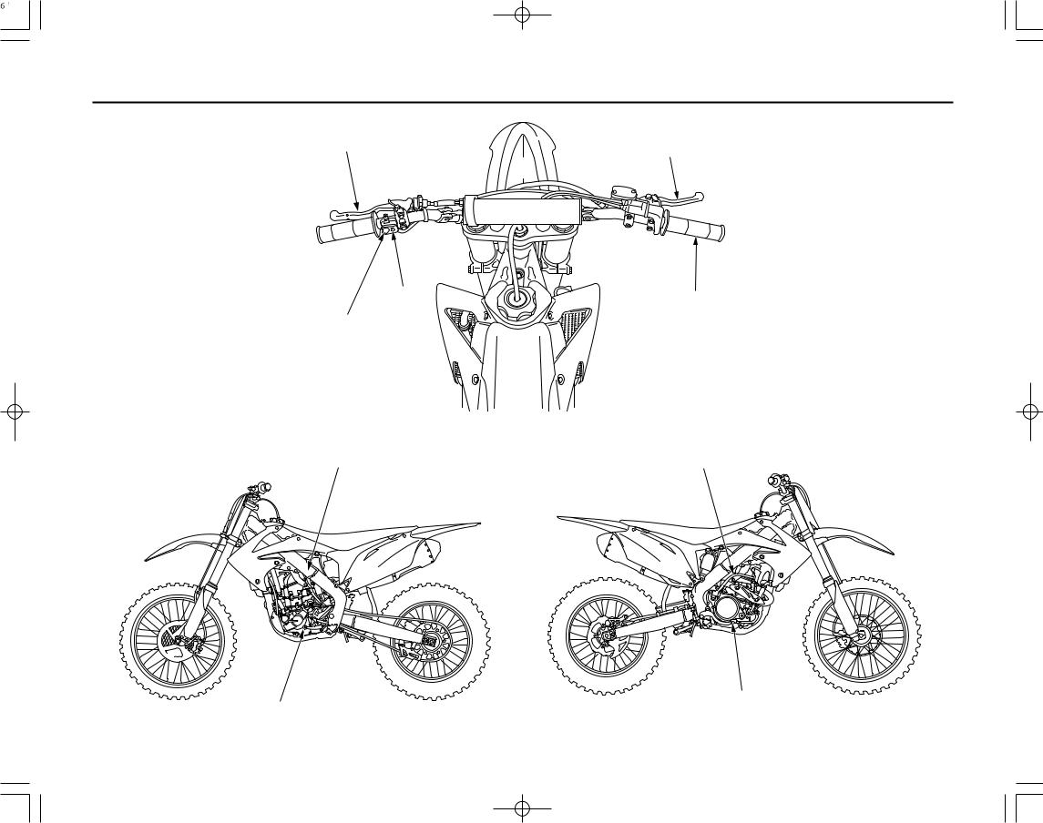
Operation Component Locations
clutch lever |
front brake lever |
|
MIL |
throttle grip |
|
engine stop button
fast idle knob |
|
(engine idle speed) |
kickstarter |
rear brake pedal
shift lever
6 Instruments & Controls
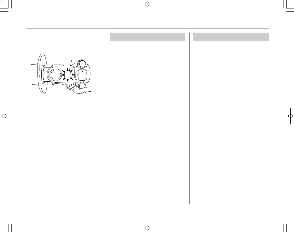
Indicator
The MIL on your CRF keeps you informed, alerts you to possible problems, and makes your riding safer and more enjoyable. Refer to the MIL frequently.
(1)
(1) MIL
The MIL flashes when there is any abnormality in the PGM-FI system. It should also light for a few seconds and then go off when the engine is started.
If the MIL comes on at any other time, reduce speed and refer to an official Honda Service Manual available for purchase from your dealer (page 160).
If the MIL does not come on when it should, have your dealer check it for problems.
MIL Blink Pattern
The MIL will blink the appropriate DTC number if the ECM detects an active problem while the engine is running at less than 5,500 rpm.
The MIL will stay ON when the engine speed is over 5,500 rpm.
The MIL has two types of blinks: a long blink and short blink. The long blinking lasts for 1.2 seconds, the short blinking lasts for 0.4 seconds. One long blink is the equivalent of ten short blinks. For example, when one long blink is followed by two short blinks, the MIL is 12 (one long blink = 10 blinks, plus two short blinks).
When the ECM stores more than one DTC, the MIL will indicate them by blinking in the order from the lowest number to highest number.
Current DTC/Freeze DTC
The DTC is indicated in two ways according to the failure status.
–In the case that the ECM detects an active problem, the MIL will come on and will start to blink the DTC when the engine is started.
–In the case that the ECM does not detect an active problem but has recorded a previous problem in its memory, the MIL will not come on. If it is necessary to retrieve any past problems stored in the memory, refer to an official Honda Service Manual.
Instruments & Controls |
7 |
Indicator
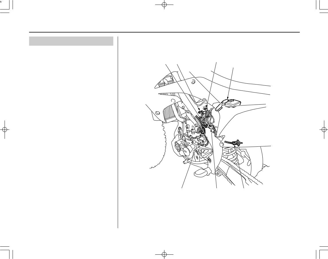
Circuit Inspection |
|
|
|
|
Always clean around the ECM and keep debris |
|
|
|
|
away from the connectors before disconnecting |
|
|
(5) |
|
them. |
(2) |
(1) |
||
(7) |
||||
|
|
|
||
A faulty PGM-FI system is often related to |
|
|
|
|
poorly connected or corroded connections. Check |
|
|
|
|
the following connections. |
|
|
|
(1)MAP sensor connector
(2)ECT sensor connector
(3)TP sensor connector
(4) IAT sensor connector
(5) Injector connector
(6) No.1/No.2 CKP sensor connector
(7) ECM connector
Remember, circuit inspection is not a “cure-all” for other problems in your engine’s PGM-FI system.
(6) |
(3) |
(4) |
8 Instruments & Controls
Indicator
DTC Index
Refer to MIL Blink Pattern on page 7.
MIL blinks |
Function Failure |
Symptom/Fail-safe Function |
|
|
|
|
|
|
|
|
|
1 |
MAP sensor circuit malfunction |
Engine operates normally |
|
|
|
|
|
2 |
MAP sensor performance problem |
Engine operates normally |
|
|
|
|
|
7 |
ECT sensor circuit malfunction |
Hard start at a low temperature |
|
|
|
|
|
8 |
TP sensor circuit malfunction |
Poor engine acceleration |
|
|
|
|
|
9 |
IAT sensor circuit malfunction |
Engine operates normally |
|
|
|
|
|
12 |
Injector circuit malfunction |
• Engine does not start |
|
• Injector, fuel pump and ignition shut down |
|||
|
|
||
|
|
|
|
19 |
No.1 CKP sensor circuit malfunction |
• Engine does not start |
|
• Injector, fuel pump and ignition shut down |
|||
|
|
||
|
|
|
|
69 |
No.2 CKP sensor circuit malfunction |
• Engine does not start |
|
• Injector, fuel pump and ignition shut down |
|||
|
|
||
|
|
|
Should be serviced by your dealer, unless the owner has proper tools and is technically qualified.
The series of 12, 19, and 69 MIL blinks cannot be checked because the engine cannot be started.
If the engine does not start, check all connector connections and/or refer to an official Honda Service
Manual (page 160) for troubleshooting of the PGM-FI symptom.
Instruments & Controls |
9 |

10 Instruments & Controls

Before Riding
Before each ride, you need to make sure you and |
Are You Ready to Ride?..................................... |
12 |
your Honda are both ready to ride. To help get |
Is Your Motorcycle Ready to Ride?................... |
13 |
you prepared, this section discusses how to |
Pre-ride Inspection........................................ |
13 |
evaluate your riding readiness, and what items |
|
|
you should check on your CRF. |
|
|
For information about suspension, steering |
|
|
damper, and other adjustments, see page 109. |
|
|
Before Riding |
11 |
Are You Ready to Ride?
Before riding your CRF for the first time, we strongly recommend that you read this owner’s manual, make sure you understand the safety messages, and know how to operate the controls.
Before each ride, it’s also important to make sure you and your CRF are both ready to ride.
For information about suspension, steering damper, and other adjustments, see page 109.
Whether you’re preparing for competition or for practice, always make sure you are:
•In good physical and mental condition
•Free of alcohol and drugs
•Wearing an approved helmet, eye protection, and other appropriate riding gear
Although complete protection is not possible, wearing the proper gear can reduce the chance or severity of injury when you ride.
WARNING
Not wearing a helmet increases the chance of serious injury or death in a crash.
Be sure you always wear a helmet, eye protection and other protective apparel when you ride.
12 Before Riding
Is Your Motorcycle Ready to Ride?
Competitive riding can be tough on a motorcycle, so it’s important to inspect your CRF and correct any problems you find before each ride. Check the following items (page numbers are at the right):
WARNING
Improperly maintaining this motorcycle or failing to correct a problem before riding can cause a crash in which you can be seriously hurt or killed.
Always perform a pre-ride inspection before every ride and correct any problems.
Pre-ride Inspection |
|
|
Check the following before each ride: |
|
|
• |
Engine oil level ............................................. |
50 |
• |
Transmission oil level................................... |
53 |
• |
Fuel line for condition .................................. |
40 |
• |
Coolant for proper level............................... |
54 |
• |
Cooling system and hoses for condition....... |
55 |
• |
Spark plug for proper heat range, carbon |
|
|
fouling and spark plug wire terminal for |
|
|
looseness ....................................................... |
67 |
• |
Air cleaner for condition and |
|
|
contamination................................................ |
56 |
• |
Clutch lever adjustment and freeplay ........... |
62 |
• |
Breather drain for cleaning ........................... |
58 |
• |
Steering head bearing and related parts |
|
|
for condition................................................ |
105 |
• |
Steering damper operation.......................... |
103 |
• |
Throttle operation ......................................... |
59 |
• |
Tires for damage or improper inflation |
|
|
pressure ........................................................ |
95 |
• |
Spokes for looseness..................................... |
94 |
• |
Rim locks for looseness................................ |
94 |
• |
Front and rear suspension for proper |
|
|
operation ................................................. |
85, 86 |
• |
Front and rear brakes, check operation ........ |
90 |
• |
Drive chain for correct slack and adequate |
|
|
lubrication................................................ |
97-98 |
• |
Drive chain sliders and drive chain rollers |
|
|
for damage or wear................................. |
97, 98 |
• |
Exhaust pipe/Muffler for looseness ............ |
100 |
•Every possible part for looseness (such as cylinder head nuts, engine mounting bolts/nuts, axle nuts, handlebar holder bolts, fork bridge pinch bolts, drive chain adjuster,
drive chain guide, wire harness connectors, |
|
kickstarter mounting bolt) ................... |
150-152 |
• Indicator .......................................................... |
7 |
Before Riding |
13 |
14 Before Riding
Basic Operating Instructions
This section gives basic information on how to |
Safe Riding Precautions................................ |
16 |
start and stop your engine as well as break-in |
Starting & Stopping the Engine ......................... |
17 |
guidelines. |
Fast Idle Knob .............................................. |
17 |
|
Preparation .................................................... |
17 |
|
Starting Procedure ........................................ |
17 |
|
How to Stop the Engine................................ |
18 |
|
Break-in Guidelines ........................................... |
19 |
Basic Operating Instructions |
15 |

Basic Operating Instructions
Safe Riding Precautions
Before riding your CRF for the first time, please review the Important Safety Precaution beginning on page 2 and the previous section, titled Before Riding.
For your safety, avoid starting or operating the engine in an enclosed area such as a garage. Your CRF’s exhaust contains poisonous carbon monoxide gas which can collect rapidly in an enclosed area and cause illness or death.
16 Basic Operating Instructions

Starting & Stopping the Engine
Always follow the proper starting procedure described below.
Your CRF can be kickstarted with the transmission in gear by pulling in the clutch lever before operating the kickstarter.
Fast Idle Knob
The fast idle knob has two functions:
•When pulled out, the fast idle knob assists in first-time start-up for cold weather starting.
•When pushed in, it acts as an idle adjustment screw. Refer to Idle Speed Adjustment on page 61.
Preparation
Make sure that the transmission is in neutral.
Starting Procedure
Always follow the proper starting procedure described as follows.
Check the engine oil, transmission oil and coolant levels before starting the engine (pages 50, 53, 54).
Cold Engine Starting
1.Shift the transmission into neutral.
2.If the temperature is 95°F (35°C) or below, pull the fast idle knob (1) fully out.
(1)
(1) fast idle knob
3.With the throttle closed, operate the kickstarter starting from the top of the kickstarter stroke, and kick through to the bottom with a rapid, continuous motion.
4.About a minute after the engine starts, push the fast idle knob back all the way to fully OFF.
If idling is unstable, open the throttle slightly.
Warm Engine Starting
1.Shift the transmission into neutral.
2.Kick-start the engine (Do not open the throttle).
If Difficult to Start After Stalling
1.Shift the transmission into neutral.
2.With the throttle fully opened, repeat kickstarter operation approximately 10 times to discharge excessive fuel from the engine.
3.Kick-start the engine. (Do not open the throttle.)
Snapping the throttle or fast idling for more than 5 minutes may cause exhaust pipe discoloration.
Basic Operating Instructions |
17 |
Starting & Stopping the Engine
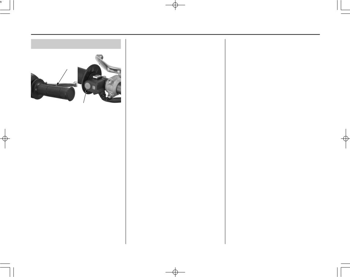
How to Stop the Engine
(1)
(2)
(1) throttle |
(2) engine stop button |
Normal Engine Stop
1.Shift the transmission into neutral.
2.Lightly open the throttle (1) two or three times, and then close it.
3.Push and hold the engine stop button (2) until the engine stops completely.
Emergency Engine Stop
To stop the engine in an emergency, push and hold the engine stop button.
18 Basic Operating Instructions

Break-in Guidelines
Help assure your CRF’s future reliability and performance by paying extra attention to how you ride during the first operating day or 15 miles (25 km).
During this period, avoid full-throttle starts and rapid acceleration.
This same procedure should be followed each time when:
•piston is replaced
•piston rings are replaced
•cylinder is replaced
•crankshaft or crank bearings are replaced
Basic Operating Instructions |
19 |

20 Basic Operating Instructions

Servicing Your Honda
Keeping your CRF well maintained is absolutely |
Before You Service Your Honda |
|
Chassis |
|
essential to your safety. It’s also a good way to |
The Importance of Maintenance ........................ |
22 |
Suspension.......................................................... |
85 |
protect your investment, get maximum |
Maintenance Safety ............................................ |
23 |
Front Suspension Inspection ........................... |
85 |
performance, avoid breakdowns, and have more |
Important Safety Precautions........................ |
23 |
Rear Suspension Inspection ............................ |
86 |
fun. |
Maintenance Schedule ....................................... |
24 |
Recommended Fork Oil .................................. |
87 |
To help keep your CRF in good shape, this |
General Competition Maintenance .................... |
26 |
Fork Oil Change.............................................. |
87 |
Before & After Competition Maintenance......... |
30 |
Brakes................................................................. |
90 |
|
section includes a Maintenance Schedule for |
Between Motos & Practice Maintenance ..... |
30 |
Wheels ................................................................ |
94 |
required servicing and step-by-step instructions |
After Competition Maintenance ................... |
30 |
Tires & Tubes ..................................................... |
95 |
for specific maintenance tasks. You’ll also find |
|
|
Drive Chain ........................................................ |
97 |
important safety precautions, information on oils, |
Service Preparations |
|
Exhaust Pipe/Muffler ....................................... |
100 |
and tips for keeping your Honda looking good. |
Maintenance Component Locations................... |
32 |
Steering Damper............................................... |
103 |
An ECM system is used on this motorcycle; |
Seat .................................................................... |
33 |
Additional Maintenance Procedures ................ |
105 |
Fuel Tank ........................................................... |
34 |
|
|
|
consequently, routine ignition timing adjustment |
Subframe ........................................................... |
36 |
Appearance Care .............................................. |
107 |
is unnecessary. If you want to check the ignition |
|
|
|
|
timing, refer to the Honda Service Manual (page |
Service Procedures |
|
|
|
160). |
Fluids & Filters |
|
|
|
An optional tool kit may be available. Check |
Fuel System ........................................................ |
40 |
|
|
Engine Oil .......................................................... |
49 |
|
|
|
with your dealer’s parts department. |
Transmission Oil ................................................ |
52 |
|
|
|
Coolant ............................................................... |
54 |
|
|
|
Air Cleaner ......................................................... |
56 |
|
|
|
Crankcase Breather ............................................ |
58 |
|
|
|
Engine |
|
|
|
|
Throttle ............................................................... |
59 |
|
|
|
Engine Idle Speed .............................................. |
61 |
|
|
|
Clutch System .................................................... |
62 |
|
|
|
Spark Plug .......................................................... |
67 |
|
|
|
Valve Clearance.................................................. |
68 |
|
|
|
Piston/Piston Rings/Piston Pin........................... |
76 |
|
|
|
|
|
|
|
Servicing Your Honda |
21 |
The Importance of Maintenance
Keeping your CRF well-maintained is absolutely essential to your safety. It’s also a good way to get maximum performance during each moto. Careful pre-ride inspections and good maintenance are especially important because your CRF is designed to be ridden in off-road competition.
Remember, proper maintenance is your responsibility. Be sure to inspect your CRF before each ride and follow the Maintenance Schedule in this section.
WARNING
Improperly maintaining this motorcycle or failing to correct a problem before you ride can cause a crash in which you can be seriously hurt or killed.
Always follow the inspection and maintenance recommendations and schedules in this owner’s manual.
22 Servicing Your Honda
Maintenance Safety
This section includes instructions on how to perform some important maintenance tasks. Some of the most important safety precautions follow. However, we cannot warn you of every conceivable hazard that can arise in performing maintenance. Only you can decide whether or not you should perform a given task.
WARNING
Failure to properly follow maintenance instructions and precautions can cause you to be seriously hurt or killed.
Always follow the procedures and precautions in this owner’s manual.
Important Safety Precautions
•Make sure the engine is off before you begin any maintenance or repairs.
This will help eliminate several potential hazards:
Carbon monoxide poisoning from engine exhaust. Be sure there is adequate ventilation whenever you operate the engine.
Burns from hot motorcycle parts. Let the engine and exhaust system cool before touching.
Injury from moving parts. Do not run the engine unless instructed to do so.
•Read the instructions before you begin, and make sure you have the tools and skills required.
•To help prevent the motorcycle from falling over, park it on a firm, level surface, using an optional workstand or a maintenance stand to provide support.
•To reduce the possibility of a fire or explosion, be careful when working around gasoline. Use only a non-flammable (high flash point) solvent such as kerosene — not gasoline — to clean parts. Keep cigarettes, sparks, and flames away from all fuel-related parts.
Servicing Your Honda |
23 |
 Loading...