


EX1000
Thank you for purchasing a Honda generator. We want to help you get the
best results from your new generator and to operate it safely. This manual
contains the information on how to do that; please read it carefully.
This owner’s manual describes the operation and maintenance of the EX650
Honda Generator. All information in this publication is based on the latest
product information available at the time of printing. Honda Motor Co., Ltd.
reserves the right to make changes at any time without notice and without
incurring any obligation. No part of this publication may be reproduced without
written permission.
This manual should be considered a permanent part of the generator and
should remain with it if it is resold.
It is illegal in some areas to operate an engine without a U.S.D.A. qualified
spark arrester: Check local laws and regulations. A spark arrester for this
generator is available from your authorized Honda generator dealer.
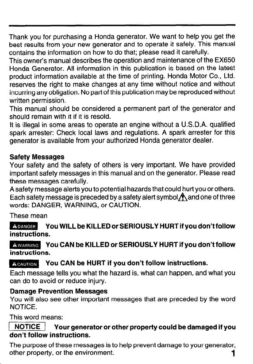
Safety Messages
Your safety and the safety of others is very important. We have provided
important safety messages in this manual and on the generator. Please read
these messages carefully.
A safety message alerts you to potential hazards that could hurt you or others.
Each safety message is preceded by a safety alert symbolBand one of three
words: DANGER, WARNING, or CAUTION.
These mean
m You WILL be KILLED or SERIOUSLY HURT if you don’t follow
instructions.
m You CAN be KILLED or SERIOUSLY HURT if you don’t follow
instructions.
m You CAN be HURT if you don’t follow inktructions.
Each message tells you what the hazard is, what can happen, and what you
can do to avoid or reduce injury.
Damage Prevention Messages
You will also see other important messages that are preceded by the word
NOTICE.
This word means:
-1 Your generator or other property could be damaged if you
don’t follow instructions.
The purpose of these messages is to help prevent damage to your generator,
other property, or the environment.
1
EX1000

CONTENTS
SAFETY
.....................................................................................................
.4
Safety Label Locations
..........................................................................
.4
Safety Information
..................................................................................
6
COMPONENT IDENTIFICATION . . . . . . . . . . . . . . . . . . . . . . . . . . . . . . . . . . . . . . . . . . . . . . . . . . . . . . . . . . . . . . . 8
CONTROLS
..............................................................................................
10
Engine Switch
.......................................................................................
10
Recoil Starter..
......................................................................................
10
Choke Lever
.........................................................................................
11
Pilot Lamp
............................................................................................
11
Ground Terminal
..................................................................................
12
Oil Alert System..
.................................................................................
.13
AC Circuit Breaker
............................................................................... .13
DC Terminals
.......................................................................................
14
DC Circuit Breaker
.............................................................................. .14
GENERATOR
USE
..................................................................................
.15
AC Operation..
.....................................................................................
.16
DC Operation
.......................................................................................
17
Connecting the battery cables
..............................................................
17
Disconnecting the battery cables
.........................................................
18
High Altitude Operation
.......................................................................
.19
PRE-OPERATION
CHECK
......................................................................
.20
Engine Oil
.............................................................................................
20
Fuel Recommendation
........................................................................ .21
STARTING/STOPPING THE
ENGINE
. . . . . . . . . . . . . . . . . . . . . . . . . . . . . . . . . . . . . . . . . . . . . . . . . . . . . 23
2
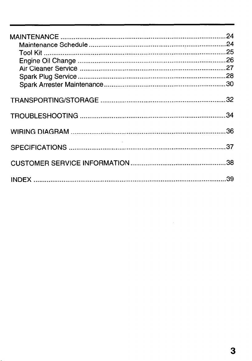
MAINTENANCE
.......................................................................................
.24
Maintenance Schedule
.........................................................................
24
Tool Kit
................................................................................................
.25
Engine Oil Change
..............................................................................
.26
Air Cleaner Service
.............................................................................
.27
Spark Plug Service
..............................................................................
.28
Spark Arrester Maintenance
.................................................................
30
TRANSPORTING/STORAGE
. . . . . . . . . . . . . . . . . . . . . . . . . . . . . . . . . . . . . . . . . . . . . . . . . . . . . . . . . . . . . . . . . . .
32
TROUBLESHOOTING
. . . . . . . . . . . . . . . . . . . . . . . . . . . . . . . . . . . . . . . . . . . . . . . . . . . . . . . . . . . . . . . . . . . . . . . . . . . . . . 34
WIRING DIAGRAM ..,................................................................................ 36
SPECIFICATIONS
. . . . . . . . . . . . . . . . . . . . . . . . . . . . . . . . . . . . . . . . . . . . . . . . . . . . . . . . . . . . . . . . . . . . . . . . . . . . . . . . . . . . 37
CUSTOMER SERVICE INFORMATION . . . . . . . . . . . . . . . . . . . . . . . . . . . . . . . . . . . . . . . . . . . . . . . . . . . 38
INDEX
. . . . . . . . . . . . . . . . . . . . . . . . . . . . . . . . . . . . . . . . . . . . . . . . . . . . . . . . . . . . . . . . . . . . . . . . . . . . . . . . . . . . . . . . . .
. . . . . . . . . . . . . 39
3
SAFETY
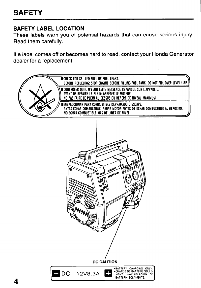
SAFETY LABEL LOCATION
These labels warn you of potential hazards that can cause serious injury.
Read them carefully.
If a label comes off or becomes hard to read, contact your Honda Generator
dealer for a replacement.
E BEFORE
FllllNC FUEL TANK. W NOT FILL OVER
ICONTR~LER QU’IL N’Y ANI FIJITE NESSENCE REPANDUE SUR L’APPAREIL
AVANT DE REFAIRE LE PLEIN: ARRiTER LE MOTEUR
NE PAS FAIRE LE PLEIN AU DESSUS DU REPERE DE NlVF.AU MAXIMUM.
ll1D” FI\“DIIPIID,L ncnnA”“nn n CPPRDC
INTES ECHAR COMBUSTIBLE: PARAR MOTOR ANTES DE ECHAR COMBUSTIBLE AL DEPOSITO.
E MAS DE LINEA DE NIVEL NO ECHAR COMBIJSTIBLI
DC CAUTION
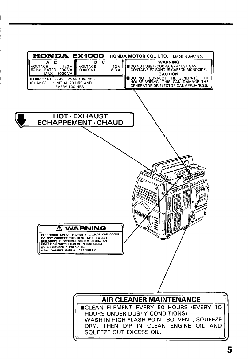
HONDA EXIOOO
HONDA MOTOR CO., LTD. MADE IN JAPAN&I
CONTAINS POISONOUS CAREON MONOXIDE.
lLUBRlCANT : 0.431 <SAE 1OW 30>
HOUSE WIRING. THIS CAN DAMAGE THE
GENERATOR OR ELECTORICAL APPLIANCES.
lCLEAN ELEMENT EVERY 50 HOURS (EVERY 10
HOURS UNDER DUSTY CONDITIONS)
WASH IN HIGH FLASH-POINT SOLVENT, SQUEEZE
DRY, THEN DIP IN CLEAN ENGINE OIL AND
5
SAFETY INFORMATION
Honda generators are designed to give safe and dependable service if
operated according to instructions. Read and understand this owner’s manual
before operating your generator. You can help prevent accidents by being
familiar with your generator’s controls, and by observing safe operating
procedures
Operator Responsibility
0 Know how to stop the generator quickly in case of emergency.
l Understand the use of all generator controls, output receptacles, and
connections.
l Be sure that anyone who operates the generator receives proper
instruction. Do not let children operate the generator without parental
supervision.
Carbon Monoxide Hazards
l Exhaust contains poisonous carbon monoxide, a colorless and odorless
gas. Breathing exhaust can cause loss of,consciousness and may lead to
death.
l If you run the generator in an area that is confined, or even partially
enclosed, the air you breathe could contain a dangerous amount of
exhaust gas. To keep exhaust gas from building up, provide adequate
ventilation.
Electric Shock Hazards
The generator produces enough electric power to cause a serious shock
or electrocution if misused.
Using a generator or electrical appliance in wet conditions, such as rain or
snow, or near a pool or sprinkler system, or when your hands are wet, could
result in electrocution. Keep the generator dry.
If the generator is stored outdoors, unprotected from the weather, check
all electrical components on the control panel, before each use. Moisture
or ice can cause a malfunction or short circuit in electrical components
which could result in electrocution.
Do not connect to a building’s electrical system unless an isolation switch
has been installed by a qualified electrician.
Fire and Burn Hazards
l The exhaust system gets hot enough to ignite some materials.
-
Keep the generator at least 1 meter (3 feet) away from buildings and
other equipment during operation.
- Do not enclose the generator in any structure.
- Keep flammable materials away from the generator.
l The muffler becomes very hot during operation and remains hot for a while
after stopping the engine. Be careful not to touch the muffler while it is hot.
Let the engine cool before storing the generator indoors.
l Gasoline is extremely flammable and is explosive under certain
conditions. Do not smoke or allow flames or sparks where the generator
is refueled or where gasoline is stored. Refuel in a well-ventilated area
with the engine stopped.
l Fuel vapors are extremely flammable and may ignite after the engine has
started. Make sure that any spilled fuel has been wiped up before starting
the generator.
7
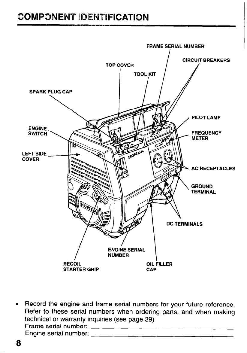
COMPONENT ODENTUFICATION
FRAME SERIAL NUMBER
I
CIRCUITBREAKERS
TOP COVER
TOOL KIT
SPARK PLUG CAP
I I
ENGINE
SWITCH
LEFT SIDE
COVER
I
J
/
PILOT LAMP
FREQUENCY
w METER
AC RECEPTACLES
GROUND
TERMINAL
I
ENGINE SERIAL
NUMBER
I
RECOIL OIL FILLER
STARTER GRIP
CAP
l Record the engine and frame serial numbers for your future reference.
Refer to these serial numbers when ordering parts, and when making
technical or warranty inquiries (see page 39)
Frame serial number:
Engine serial number:
8
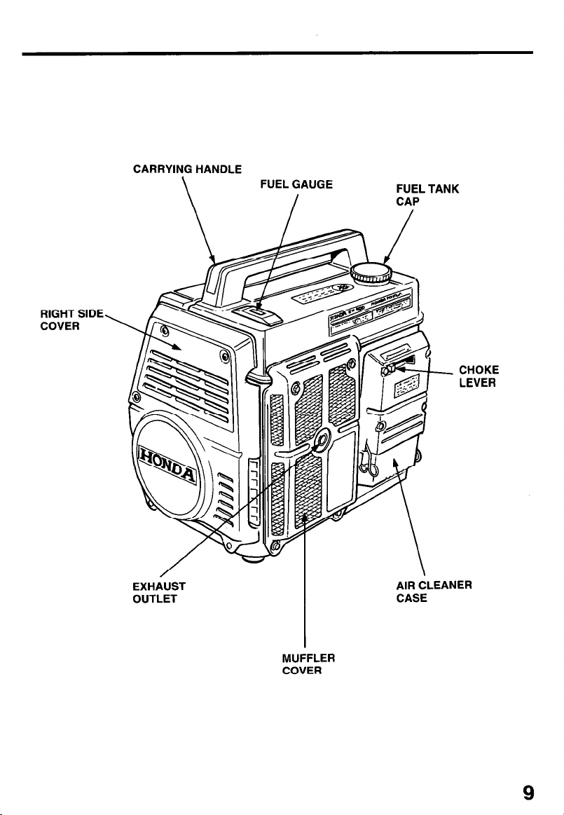
CARRYING HANDLE
\
FUEL GAUGE
FUEL TANK
I
CAP
RIGHT SIDE,
COVER
CHOKE
LEVER
EXHdUST
AIR CLEANER
OUTLET
CASE
MUFFLER
COVER
9
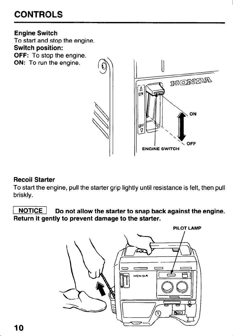
CONTROLS
Engine Switch
To start and stop the engine.
Switch position:
OFF: To stop the engine.
ON: To run the engine.
0
-3
ENGINE SWITCH
Recoil Starter
To start the engine, pull the starter grip lightly until resistance is felt, then pull
briskly.
(1 Do not allow the starter to snap back against the engine.
Return it gently to prevent damage to the starter.
PILOT LAMP
10
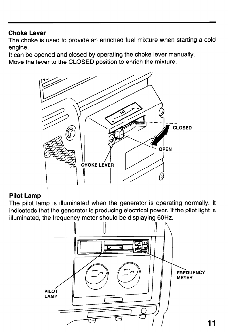
Choke Lever
The choke is used to provide an enriched fuel mixture when starting a cold
engine.
It can be opened and closed by operating the choke lever manually.
Move the lever to the CLOSED position to enrich the mixture.
‘CLOSED
Pilot Lamp
The pilot lamp is illuminated when the generator is operating normally. It
indicateds that the generator is producing electrical power. If the pilot light is
illuminated, the frequency
meter should be displaying 60Hz.
1’ I\
,
11
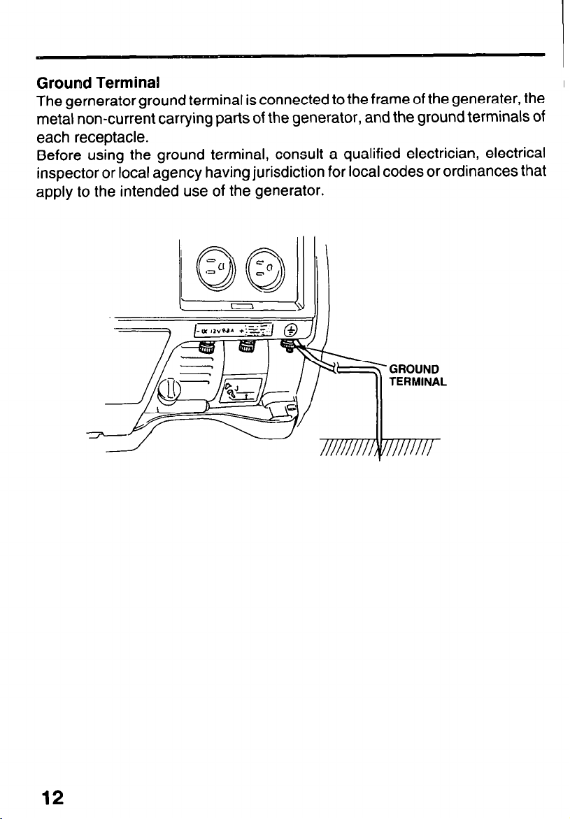
Ground Terminal
I
The gernerator ground terminal is connected to the frame of the generater, the
metal non-current carrying parts of the generator, and the ground terminals of
each receptacle.
Before using the ground terminal, consult a qualified electrician, electrical
inspector or local agency having jurisdiction for local codes or ordinances that
apply to the intended use of the generator,
12
 Loading...