

Item # ________________________________
Quantity _______________________________
C.S.I. Section 11400
FD3-50 FD3-75 FD3-125
701 S Ridge Avenue, Troy, OH 45374
1-888-4HOBART • www.hobartcorp.com
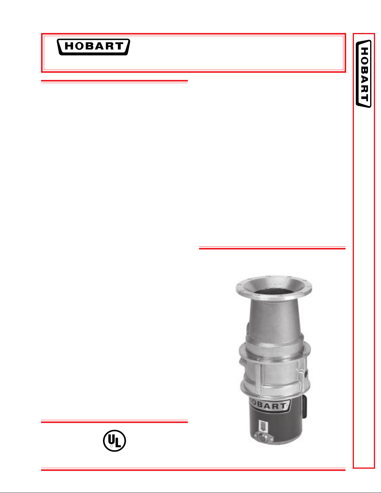
COMPACT SIZE BIG VERSATILITY
Hobart Disposers are well recognized for quality
and capacity. They’re designed with your needs in
mind - built with a large capacity for food wastes.
The following pages illustrate the variations of
controls and accessories available to make these
food waste disposers the most versatile equipment for small to medium sized clean-up systems.
SPECIFICATIONS
Listed by Underwriters Laboratories Inc. and meets requirements of
A.S.S.E. Standard No. 1009 (50 Hz. Electrical Specifications not U L
Listed.)
MOTORS: Continuous duty rating, equipped with
manual reset thermal overload inherent protector.
Permanently lubricated ball bearings for upper
and lower shelf support. Upper bearing is sealed
on both sides.
FOODWASTE DISPOSERS
MOTOR SHAFT SEAL: Face-type seal consists
of sintered bronze mating ring and spring loaded
carbon ring insert in chemical resistant neoprene
bellows. Mating surfaces are protected from grit or
fibers by being recessed into flywheel. Should any
moisture pass this seal, a flinger and drain tube
are provided to insure immediate removal. In
addition, a lip-type oil seal (located beneath the
bearings) is an “added protection” water seal.
DRAIN CONNECTOR: A chrome plated brass tailpiece is provided for connection to a 11⁄2" standard
drain trap.
DUAL DIRECTIONAL GRINDING: All Disposers
operate in either direction of flywheel rotation.
Direction of rotation can be controlled by the
operator (to increase life and efficiency of grinding
elements — back flywheel free of a “jam”) when
installed with Control Groups 2, 3 or 4.
WEIGHT: Shipping – Approx. 60 lbs. (does not
include accessory group or controls).
FD3-50 FD3-75 FD3-125 FOODWASTE DISPOSERS
HOUSINGS: Heavy aluminum grind and discharge
housings. Four bolts fasten the motor unit to the
grind chamber, permit easy removal.
MOUNTING: All Hobart Disposers (except when
using accessory group E), fasten to 7" I.D. (throat
opening) cones. A vinyl isolating ring eliminates
metal-to-metal contact at the cone mounting,
reduces vibration and noise transmission.
STATIONARY SHREDDER RING: 13⁄4" high,
4 machine ground primary action breaker bars,
42 secondary action grinding teeth.
FLYWHEEL: Breaker blade, mounted at center,
speeds grinding, prevents objects from “riding” at
center. Two hardened stainless steel cutter blocks
(fastened to flywheel with nylock screws) are
replaceable, can be indexed for new cutting
edges. Ni-Resist flywheel is 63⁄16" diameter,
slots undercut the shredder ring to assure that
particles are cut to proper size before passing
to the drain line.
R
Long Housing Model
F-8567 – FD3-50 FD3-75 FD3-125 Foodwaste Disposers Page 1 of 4
FD3-50 FD3-75 FD3-125
FOODWASTE DISPOSERS
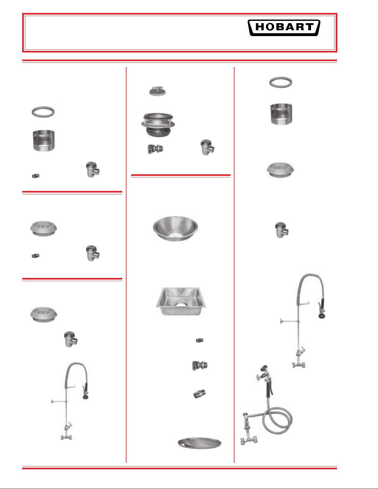
ACCESSORY GROUPS
GROUP A (For use with long upper
housing only.)
Vinyl Scrapping
Ring
Stainless Steel
Silver-Saver Sleeve
with Side Feed
Hole
Water Swirl Vacuum Breaker
GROUP B (For use with long upper
housing only.)
Vinyl Silver-Saver
Splash Guard Ring
Water Swirl Vacuum Breaker
GROUP C (For use with long upper
housing only.)
Vinyl Silver-Saver
Splash Guard Ring
GROUP E (For use with short upper
housing only.)
Fixed Direction Vacuum Breaker
Water Inlet for Sink
ACCESSORY
COMPONENTS
CONES-SINK – Stainless Steel
Cone 15" I.D. w/hole for water swirl
inlet ........................................... 204007
Cone 18" I.D. w/hole for water swirl
inlet ........................................... 204004
Cone 15" I.D. w/out swirl hole ... 204006
Cone 18" I.D. w/out swirl hole ... 204003
Sink 16" x 20" x 7" (7" opening)
w/hole for water inlet ............ 204015-2
NOTE: For use with
short Upper Housing
Foodwaste Disposer
only.
Cover Stopper and
Sink Adapter
Assembly for 31⁄2"
to 4" Sink Opening
Part No.
701 S Ridge Avenue, Troy, OH 45374
1-888-4HOBART • www.hobartcorp.com
CONE FEEDING ACCESSORIES
Part No.
Vinyl Scrapping Ring .................. 202113
Stainless Steel Silver-Saver Sleeve
with side feed hole .................. 203870
SILVER-SAVER SPLASH
GUARD RING
Vinyl Silver-Saver and Splash Guard
Ring (for 7" opening cones, sinks
and adapter) ............................ 202120
VACUUM BREAKERS –
Chrome Plated
3
⁄4" ................................................. 277112
PRE-RINSE SPRAYS
PR-3 Heavy-duty
Flexible Pre-Rinse
Spray (38" high
with wall
bracket)
ML-32333
WATER INLETS
Vacuum Breaker
Cone Water Swirl Inlet 1⁄2" N.P.T.
............................................. 204380
Fixed Direction Water Inlet (for sinks or
troughs) 1⁄2" N.P.T............... 204346
FLOW CONTROL
5 Gallons per minute for Models
FD3-50 through FD3-125 3⁄4" N.P.T.
............................................. 201721
PR-4 Utility Spray
(with wall bracket)
ML-32334
CONE COVER –
STAINLESS STEEL
Pre-Rinse Spray
with Wall Bracket
15" Cone Cover w/feed hole ...... 204024
18" Cone Cover w/feed hole ...... 204023
Adapters are available to install Hobart Disposers
on existing competitive cones. See Form F-7543.
Page 2 of 4 F-8567 – FD3-50 FD3-75 FD3-125 Foodwaste Disposers

FD3-50 FD3-75 FD3-125
701 S Ridge Avenue, Troy, OH 45374
1-888-4HOBART • www.hobartcorp.com
FOODWASTE DISPOSERS
ELECTRICAL CONTROL GROUPS Listed by Underwriters Laboratories Inc., for use with FD Disposers
(50 Hz. Electrical Specifications not submitted for UL Listing.)
Group 2 - For all Models
Includes:
Magnetic Contactors
Pushbutton Start and Stop
Automatic Reversing
Made from a NEMA 12 Enclosure
Solenoid Valve
Approximate
Shipping Wt. 31 lbs.
Group 3 - For all Models
Includes:
Magnetic Contactors
Pushbutton Start and Stop
Automatic Reversing
Low Water Pressure Cut-off
Time Delay for water after shut-off
Line Disconnect
Solenoid Valve
Made from a NEMA 12 Enclosure
Model H.P. Ph. Hz. Volts Rated Amps
160120/208-240 9.2/4.2-4.6
FD3-50
FD3-75
FD3-125
FD3-50
FD3-75
FD3-125
The dash (-) between voltages represents the range (low-high) of voltage operation. The slant (/) line
indicates the dual voltage operation accomplished by motor lead connection: follow connecting diagram on
motor. (50 Hz. models not submitted for U L Listing.)
1
⁄
2
360208-240/480 1.8-2.0/1.0
160120/208-240 10.8/5.3-5.4
3
⁄
4
360208-240/480 2.6-3.0/1.5
160120/208-240 14.8/7.7-7.4
11⁄
4
360208-240/480 4.2-4.0/2.0
150110-120/220-240
1
⁄
2
350220-240/380-415
150110-120/220-240
3
⁄
4
350220-240/380-415
150110-120/220-240
11⁄
4
350220-240/380-415
Contact
Customer
Service
For
Amperage
Data
Approximate
Shipping Wt. 38 lbs.
Group 4 - For Models thru
FD3-200
Includes:
Manual Reversing Switch
NEMA 1 Enclosure Standard
NEMA 4 Enclosure Optional
Not available above 250 volts
Optional Solenoid Valve
Approximate
Shipping Wt. 11 lbs.
SAMPLE SPECIFICATION
FD3-75 — B — 2 (230/60/3)
Electrical Specifications
Electrical Control Group
Accessory Group
Model Number
Cut hole 19" for 18" cone. Hole to be 16" for 15" cone.
Solenoid must be installed in upright position.
Disposer may be easily rotated for better drain line connection.
Center line at wall outlet of trap should not be higher than center
line of disposer discharge opening.
If water pressure is in excess of 60 P.S.I. install a pressure
reducing valve.
F-8567 – FD3-50 FD3-75 FD3-125 Foodwaste Disposers Page 3 of 4

FD3-50 FD3-75 FD3-125
FOODWASTE DISPOSERS
DETAILS AND DIMENSIONS
15" or 18"
5"
61⁄2"
83⁄8"
10"
WASTE
OUTLET
WASTE
EXIT
20" FD3-125 1 PH.
193⁄8" FD3-50, 75 1 PH.
183⁄4" FD3-50, 75, 125 3 PH.
1
21
⁄8" FD3-125 1 PH.
1
20
⁄2" FD3-50, 75 1 PH.
197⁄8" FD3-50, 75, 125 3 PH.
701 S Ridge Avenue, Troy, OH 45374
1-888-4HOBART • www.hobartcorp.com
71⁄4"
7"
9"
ROUGH IN
WASTE OUTLET
WASTE EXIT
47⁄32"
67⁄16"
813⁄32"
LONG UPPER HOUSING
NOTE: Specify 15" or 18" Cone When Desired.
TYPICAL INSTALLATION - Unit with Long Upper Housing.
SWIRL & FLOW CONTROL
11⁄2" WASTE LINE
161/2"
PLUMBING
ROUGH-IN
SHORT UPPER HOUSING
VACUUM BREAKER
SOLENOID VALVE
FURNISHED WITH CONTROL
GROUPS 2 & 3
PRESSURE SWITCH, TEE & NIPPLE
FURNISHED WITH
CONTROL GROUP 3 ONLY
PRESSURE REDUCING
VALVE - BY OTHERS
SHUT — OFF
VALVE BY OTHERS
As continued product improvement is a policy of Hobart, specifications are subject to change without notice.
Page 4 of 4 F-8567 – FD3-50 FD3-75 FD3-125 Foodwaste Disposers
F-8567 (REV. 8/03) LITHO IN U.S.A. (H-01)
Printed On Recycled Paper
 Loading...