

Page 1
Operating Instructions
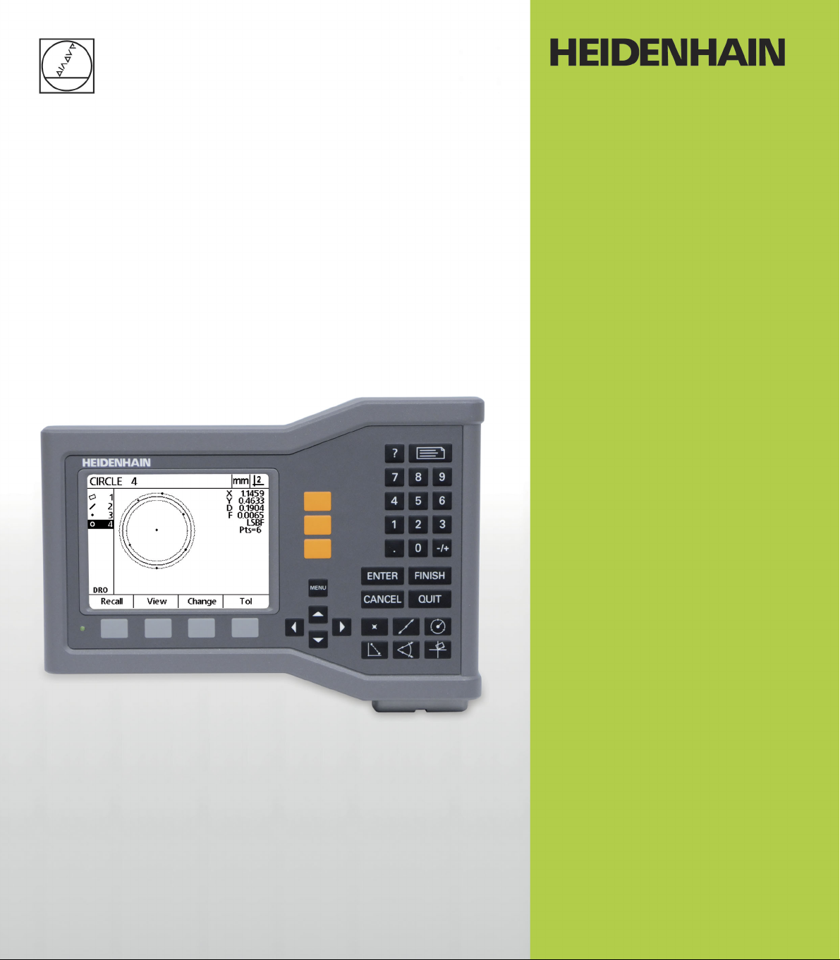
ND 120
QUADRA-CHEK
Software Version
2.0.x
English (en)
5/2013
Page 2

Page 3
Introduction
11
12
13
141519
16
1718110
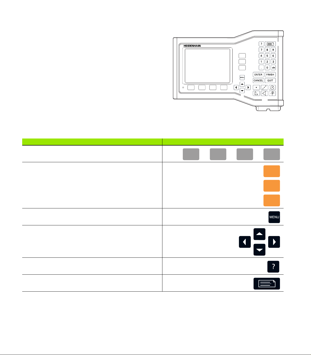
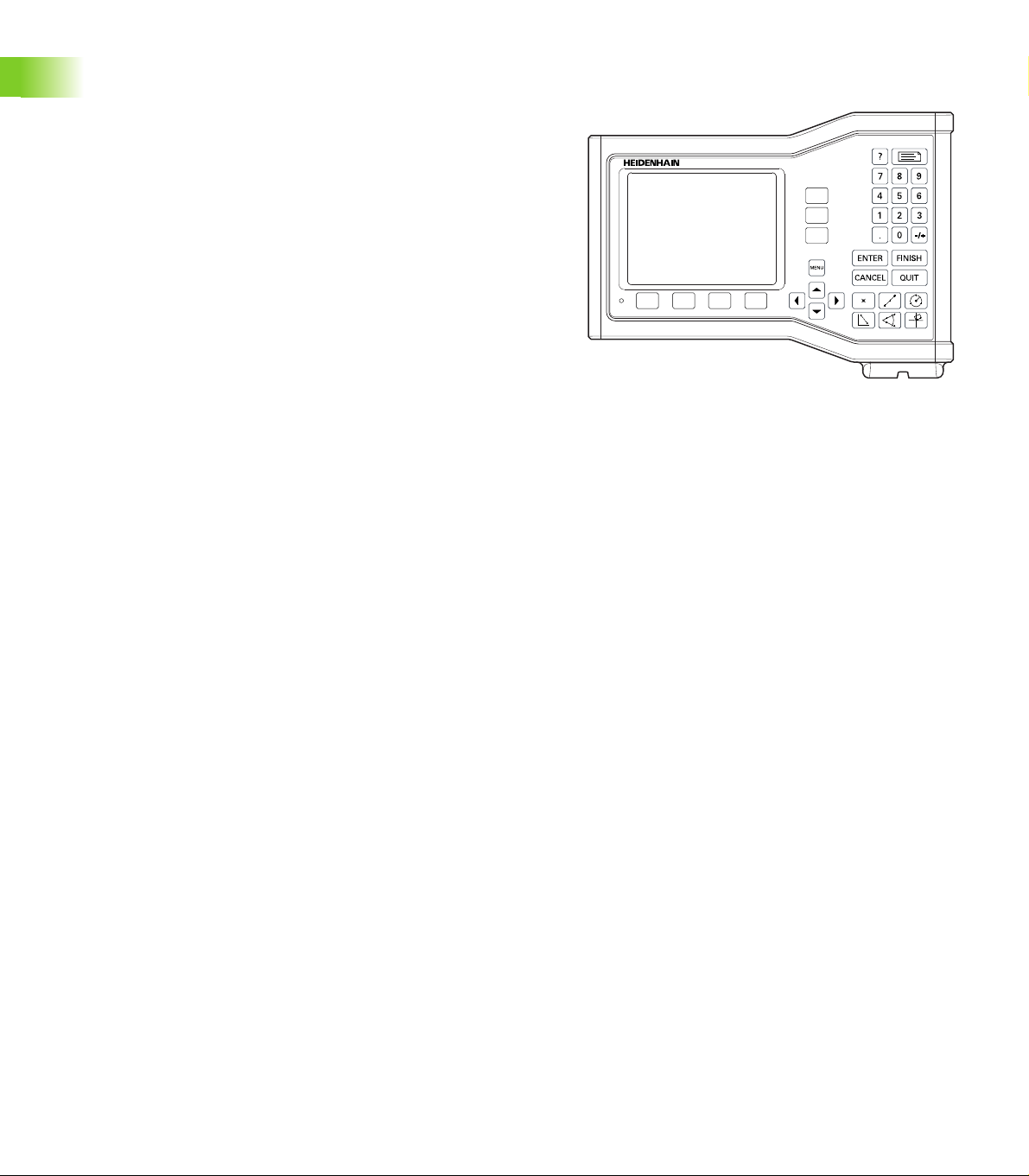
1 LCD screen
2 Soft keys
3 Axis keys
4 Menu key
5 Arrow keys
6 Help key
7 Send key
8 Numeric keypad
9 Command keys
10 Measure keys
Front panel keys
Panel keys are used to initiate feature measurements, apply
tolerances, send reports of measurement results and configure
operational parameters.
Panel function key Panel key
Soft keys: Functions change in support of the activities displayed
on the LCD.
Axis keys: Select axes for zeroing or presetting datums prior to
measurements.
Menu key: Displays soft key menus for system setup, extra
functions and clearing data.
Arrow keys: Used to scroll through lists and navigate menus and
setup screen data fields. The Up Arrow key is also used to begin
a feature construction process, as described in "Constructing Part
Features" on page 45.
Help key: Displays help topics for current function.
Send key: Used to transmit measurement results to a computer.
ND 120 QUADRA-CHEK 3
Page 4
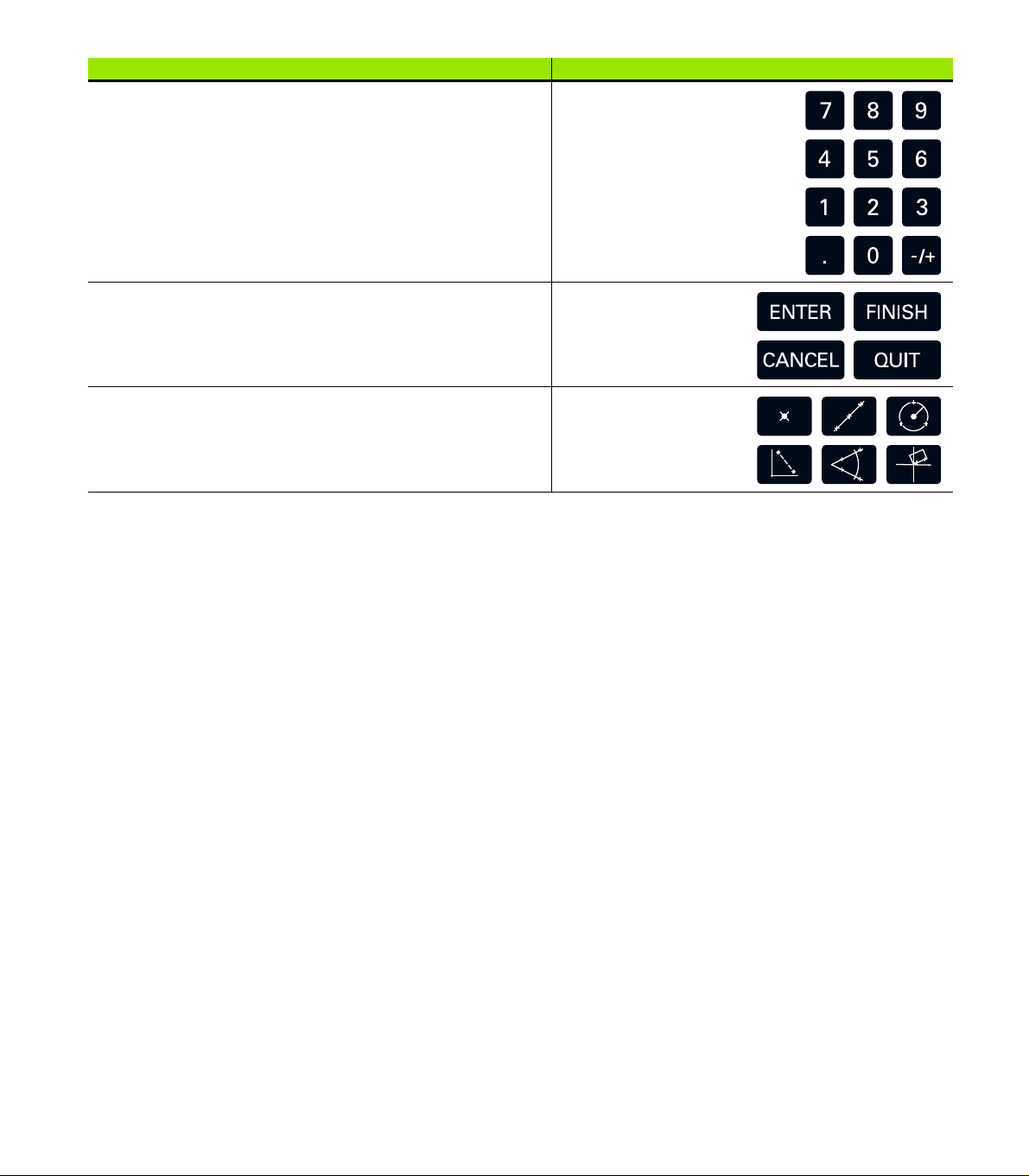
Panel function key Panel key
Numeric keypad: Used to enter numeric data.
Command keys: Control measurement and data entry
processes.
Measure keys: Select a feature measurement type. Feature
measurement types include points, lines, circles distances,
angles and skew alignments.
4 Preface
Page 5
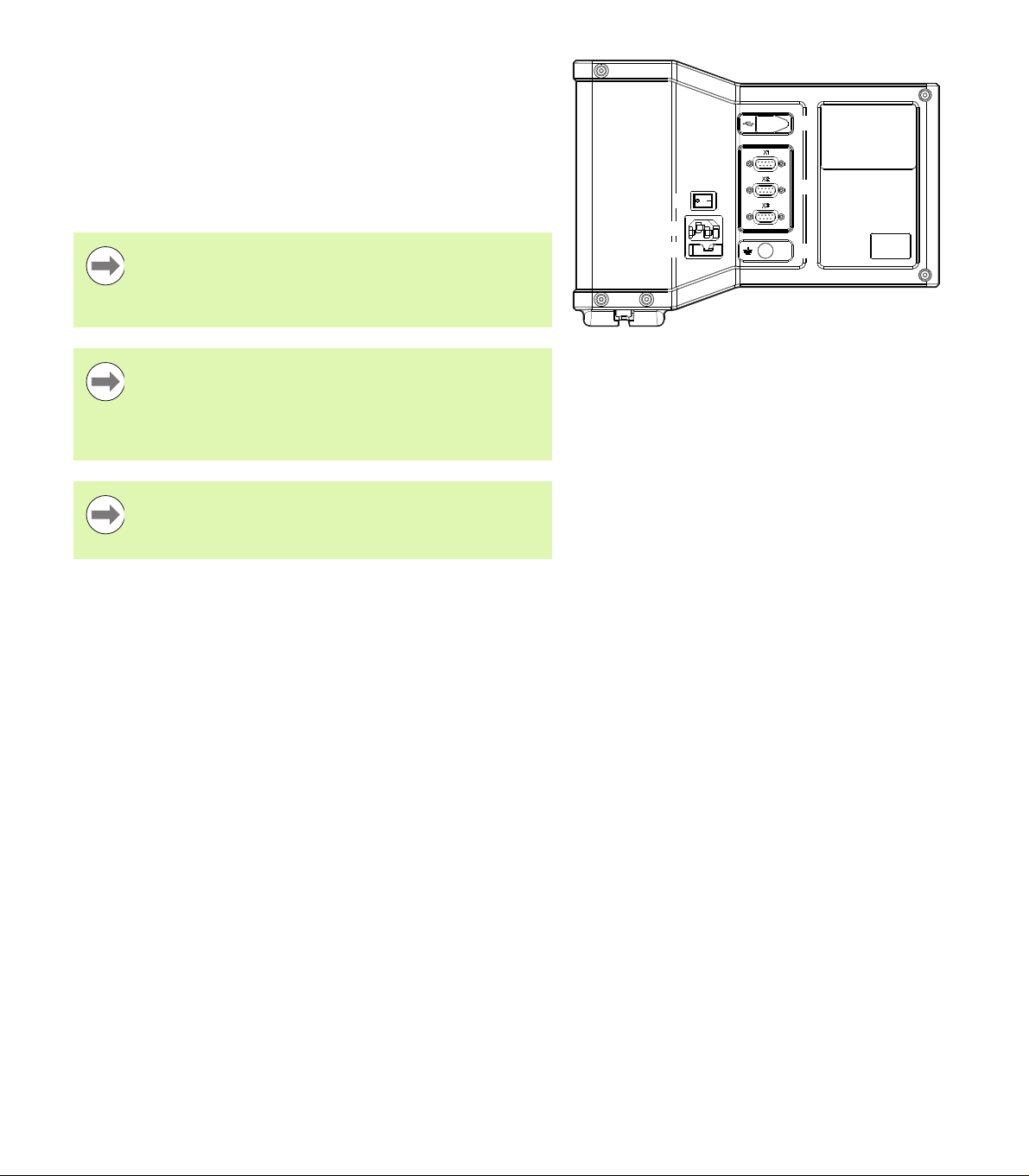
Rear panel
11
1
21415
16
1
3
1 Power switch
2 Power cord connector
3 Replaceable fuse holder
4 USB (type B) interface
5 Encoder inputs
6 Earth (ground) terminal
Notice
Do not engage, or disengage any connections while the
unit is under power. Damage to internal components may
result.
Notice
It is necessary to connect the earth (ground) terminal on
the rear of the product to the star point of machine ground.
Minimum cross section of the connecting wire: 6 mm2.
Never use this equipment without proper grounding.
Notice
Periodically inspect the display unit, connectors and
connection cables for damage and poor connections.
ND 120 QUADRA-CHEK 5
Page 6

Information contained in this manual
These Operating Instructions cover the operation, installation, setup
and specifications of the following models:
Product name ID Index
ND 122 QUADRA-CHEK 749315-02 -, A, B
ND 122 QUADRA-CHEK 749315-03 -, A, B
ND 123 QUADRA-CHEK 749315-12 -, A, B
ND 123 QUADRA-CHEK 749315-13 -, A, B
Operating information is contained in chapter 1. Installation, setup
instructions and specifications are contained in chapter 2. For detailed
Installation Instructions refer to the ND 120 Installation Instructions
(ID 1029950-xx).
Software version
The software version is shown in the About setup screen. See
"Language selection and product version" on page 70.
6 Preface
Page 7

Fonts used in this manual
The following fonts are used to indicate operator controls or to show
emphasis:
Operator controls - Soft Keys and other Panel Keys are shown in
letter gothic bold font.
Emphasis - Items of special interest or concepts that are
emphasized to the user are shown in bold type.
Showing sequences of key presses
The user performs sequences of soft key and panel key presses to
measure features and complete other tasks. These sequences are
indicated using text as shown in the following example:
Press the MENU key, press the Clear soft key and then press the Yes
soft key is sometimes abbreviated as:
Press MENU>Clear>Yes
ND 120 QUADRA-CHEK 7
Page 8
Safety symbols
Where the following safety symbols appear on the product they alert
you to important safety information.
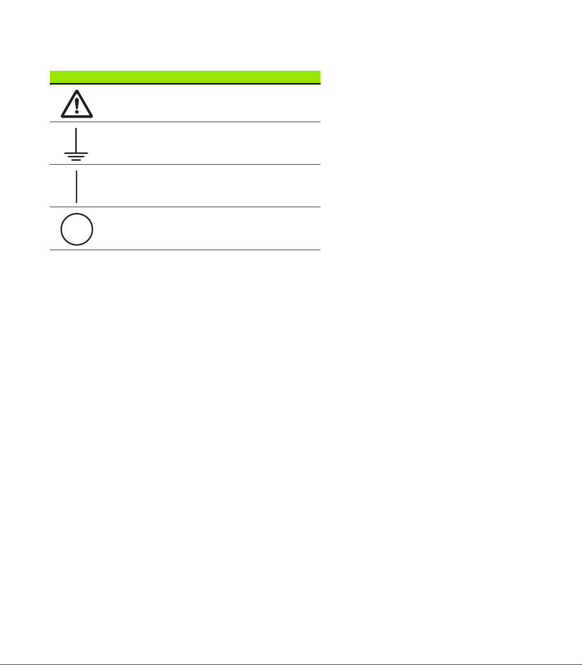
Symbol Description
This symbol denotes “Caution, risk of danger”. Refer
to the accompanying information or documentation to
protect against personal injury or damage to the unit.
This symbol is used to denote “Earth (ground)
terminal”.
This symbol is used to denote the power switch “On
(supply)” position.
This symbol is used to denote the power switch “Off
(supply)” position.
8 Preface
Page 9
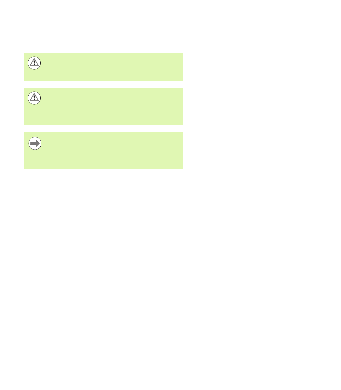
Messages shown in these instructions
The following examples show how safety, property damage and
general advice messages are shown in these instructions. Read and
understand these types of messages before proceeding to prevent
personal injury or property damage.
Messages about other safety messages. These
supplemental directives do not address specific hazards,
but instead provide information that promotes awareness
and use of specific safety messages.
Warning!
Messages that provide information about the nature of a
hazardous situation, the consequences of not avoiding a
hazardous situation, and method(s) for avoiding a
hazardous situation.
Notice
Messages that provide information primarily about
situations that can lead to property damage, the potential
consequences of not avoiding the situations, or method(s)
for avoiding the situations and general advice messages.
ND 120 QUADRA-CHEK 9
Page 10
Safety
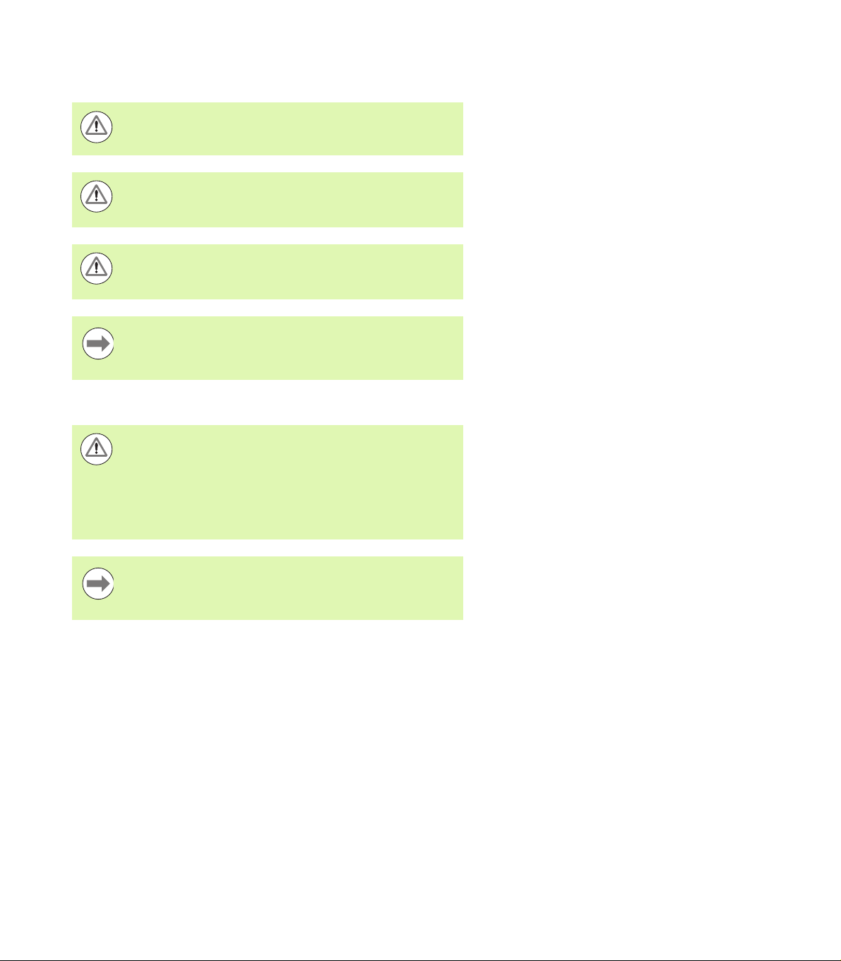
The following messages provide safety information for preventing
personal injury and product damage:
Read and understand these instructions before use to
avoid the possibility of personal injury or death.
Hazardous live parts may be exposed if the unit is opened.
Do not open the unit. There are no serviceable items
inside.
The protection provided by the equipment may be
impaired if used in a manner not specified. Do not use this
product in any way other than its intended use.
Notice
For safety, operation and handling of the unit, keep this
document for future reference.
Cleaning
Warning! Risk of electrical shock
While cleaning it is possible to conduct electricity from
hazardous live parts if liquid enters the product.
To avoid the hazard, always power off the product,
disconnect the power cable and never use a cloth that is
dripping or saturated with water.
Notice
Never use abrasive cleaners, strong detergents or
solvents to avoid damage to the product.
Power-off the DRO.
Disconnect the power cable from the source of power.
Clean exterior surfaces with a cloth dampened with water and a
mild detergent.
Measurement axes
The ND 120 DRO’s display 2 or 3 axes depending on the model
purchased. DRO screen images used throughout this manual show
different numbers of axes and are for illustration only.
10 Preface
Page 11
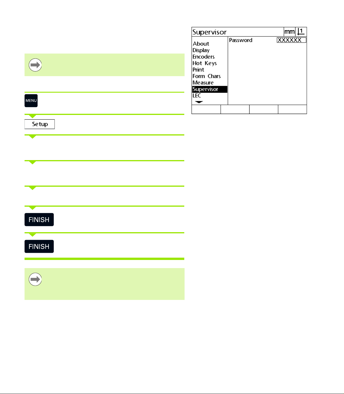
Supervisor password
Critical setup parameters are password protected. Only qualified
personnel should be given password access to setup screen
parameters. This prevents inadvertent adjustments to the installation
setup parameters.
Notice
The password is 070583.
Enter the supervisor password
Press the MENU key to display the menu soft keys.
Press the Setup soft key to display the setup menu.
Navigate up or down in the menu to highlight the Supervisor menu
item using the Up/Down Arrow keys.
Navigate from the menu to the Password setup field using the
Right Arrow key.
Enter the supervisor password 070583 using the numeric keypad.
Press the FINISH key to save the password and return
to the setup menu.
Press the FINISH key to return to the DRO.
Notice
Supervisors may wish to remove this page from the
Operating Instructions after initially setting up the readout
system. Retain in a safe place for future use.
ND 120 QUADRA-CHEK 11
Page 12

12 Preface
Page 13

1 Operation ..... 17
1.1 Overview ..... 18
1.2 Basic Functions ..... 19
Initial power-up ..... 19
Establishing a repeatable machine zero ..... 20
Power-off ..... 20
Panel key descriptions ..... 21
Display modes and soft key layout ..... 24
DRO mode screen ..... 24
Feature evaluation mode screens and soft keys ..... 25
Feature measurement mode screen and soft keys ..... 26
Menus ..... 27
1.3 Preparing to Measure ..... 30
Power-up ..... 30
Establish machine zero ..... 30
Select the desired annotation ..... 31
Toggle between forward and backward annotation ..... 31
Align the part to a measurement axis ..... 32
Perform a part alignment (Skew) ..... 32
Establish a datum ..... 33
Probe skew and part edge lines for point construction ..... 33
Construct a datum point from line features ..... 34
Zeroing the datum ..... 34
Presetting the datum ..... 35
1.4 Measuring Part Features ..... 36
Part features ..... 36
Feature list ..... 36
Probing part features ..... 36
Probing with crosshairs ..... 36
Measuring features ..... 37
Auto repeat ..... 37
Measuring points ..... 38
Measuring lines ..... 39
Measuring circles ..... 40
Measuring distances ..... 41
Measuring angles ..... 42
ND 120 QUADRA-CHEK 13
Page 14

1.5 Creating Part Features ..... 43
Created features ..... 43
Creating features ..... 43
Example of creating a feature ..... 44
1.6 Constructing Part Features ..... 45
Constructed features ..... 45
Constructing features ..... 45
Example of constructing a feature ..... 46
More feature construction examples ..... 47
1.7 Tolerances ..... 50
Feature tolerances ..... 50
Applying tolerances ..... 51
Example of applying a tolerance ..... 52
1.8 Reporting ..... 54
Reporting ..... 54
Sending reports ..... 54
1.9 Error Indications ..... 55
Scale errors ..... 55
14
Page 15

2 Installation, Setup and Specifications ..... 57
2.1 Installation, and electrical connection ..... 58
Items supplied ..... 58
Accessories ..... 58
Installation ..... 59
Tilting base (ID 625491-01) (optional) ..... 59
Mounting arm (ID 382893-01) (optional) ..... 59
Mounting frame (ID 647702-01) (optional) ..... 60
Electrical connection ..... 61
Electrical requirements ..... 61
Environmental conditions ..... 61
Power connector wiring ..... 61
Replacing a fuse ..... 62
Connecting encoders ..... 63
Connecting a computer ..... 64
Connecting to Hyperterminal ..... 65
2.2 Software setup ..... 66
Setup menu ..... 67
Setup example: entering the supervisor password ..... 68
Order of setup ..... 69
Language selection and product version ..... 70
Axis configuration ..... 71
Supervisor password and program unlocking ..... 72
Sending and receiving settings data ..... 73
Encoder configuration ..... 76
Encoders screen ..... 76
Misc screen ..... 79
Stage squareness calibration ..... 80
Error correction ..... 81
Linear error correction (LEC) ..... 82
Segmented linear error correction (SLEC) ..... 84
Nonlinear error correction (NLEC) ..... 88
NLEC by measuring points on a calibration grid ..... 90
NLEC by importing an NLEC data .txt file ..... 92
Saving an NLEC data .txt file ..... 93
Measurement scaling for parts that expand or shrink ..... 94
Scale Factor screen ..... 94
Measurement configuration ..... 95
Measure screen ..... 95
Display formatting ..... 97
Display screen ..... 97
Hot key assignments ..... 100
Hot keys screen ..... 100
Print formatting ..... 103
Print screen ..... 103
Form Chars screen ..... 107
2.3 Specifications ..... 108
Dimensions ..... 109
ND 120 QUADRA-CHEK 15
Page 16

16
Page 17

Operation
Page 18
1.1 Overview
The ND 120 is an advanced digital readout (DRO) system for
performing 2 or 3 axis measurements using TTL encoders. The
ND 120 can be used with optical comparators, toolmaker’s
microscopes or video measurement systems as part of in-line
production or in final quality inspection.
The following functions are available:
1.1 Overview
Reference mark evaluations for distance-coded and single reference
encoders
Linear, segmented linear and nonlinear error correction
Scaling factor for parts that expand or shrink
Multilingual LCD user interface: language is selected by the user
Soft key functions under LCD change to support different user
activities
Arrow keys for easy navigation of lists and menus
Skew compensation for part alignment prior to measurement,
eliminating the need for time-consuming fixturing
Two datums for absolute and incremental measurements
Axis zero and preset keys for establishing datums
Easy selection of feature measurement type using clearly marked
measure function keys:
Points, lines, circles, distances, angles
Skew for part alignment
Feature measurement can include:
Dimensional measurements of geometric part features
Creation of features by entering dimensional data
Construction of new features from existing features
Applying tolerances
Number keypad with:
Number keys for data entry
Decimal point and +/- keys for data entry
User-defined hot keys that program panel keys to initiate commonly
used functions.
Reports of measurement results sent to a computer over USB-to-
Serial connection
User-defined settings sent to a computer over USB-to-Serial
connection
ND 123 Front panel
18 1 Operation
Page 19
1.2 Basic Functions
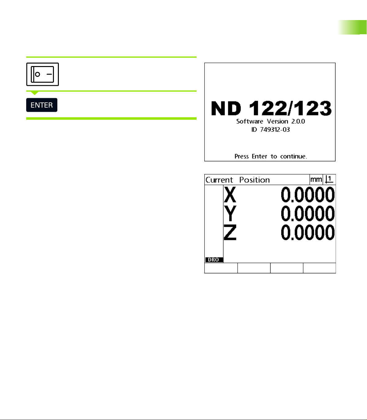
Initial power-up
Switch on the power (located on the rear of the
enclosure). After switching the power on, or after a
power failure, the power-up screen will be displayed.
Press the ENTER key to advance from the power-up
screen to the DRO.
Your DRO is now ready for operation and is in the Current Position
operating mode. Encoder position values will be displayed for all axes.
1.2 Basic Functions
Power-up screen
DRO screen
ND 120 QUADRA-CHEK 19
Page 20
Establishing a repeatable machine zero
If your DRO was configured to establish a machine zero upon powerup, a message will be displayed asking you to cross reference marks
or enter hard-stop axis reference positions. The machine zero is used
by the DRO to apply error correction data as measurements are
performed. To establish a repeatable machine zero you must either:
Move the stage to have encoder reference mark crossings
recognized on each axis or
move the stage to the hard-stop reference position and press ENTER
on each axis when no encoder reference marks are present.
1.2 Basic Functions
Power-off
Notice
If the requirement to cross reference marks is bypassed
by pressing the Cancel soft key, error correction data that
might be stored in your DRO will not be applied.
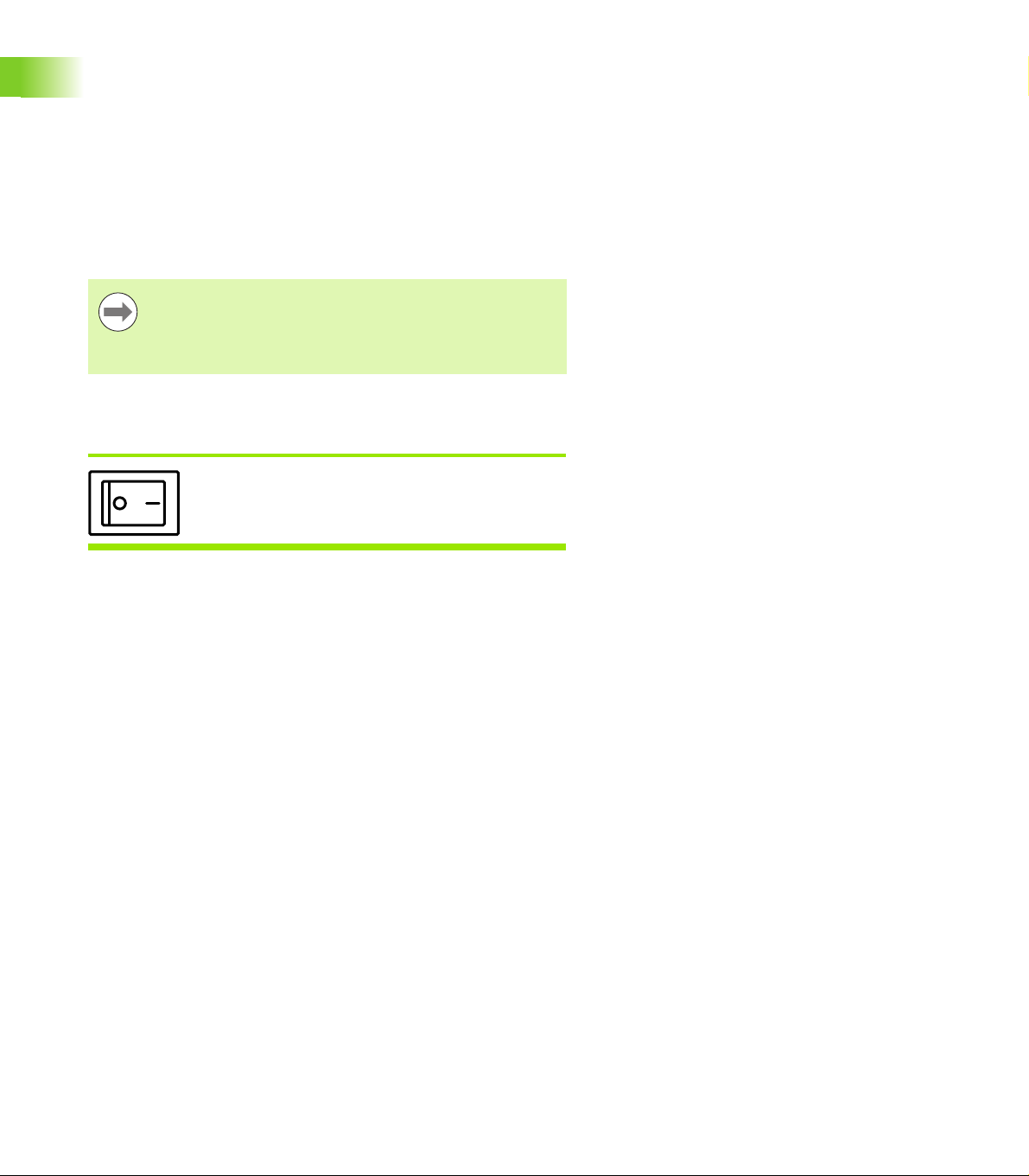
Switch the power off. The parameter settings and
error compensation tables that have been saved
during operation will be retained in memory.
20 1 Operation
Page 21
Panel key descriptions
Descriptions of panel key functions are provided in the following
pages for Measurement function, Command, Help, Axis, Send and Menu
keys. Soft key functions are also described later in the next section as
part of screen and soft key layout descriptions.
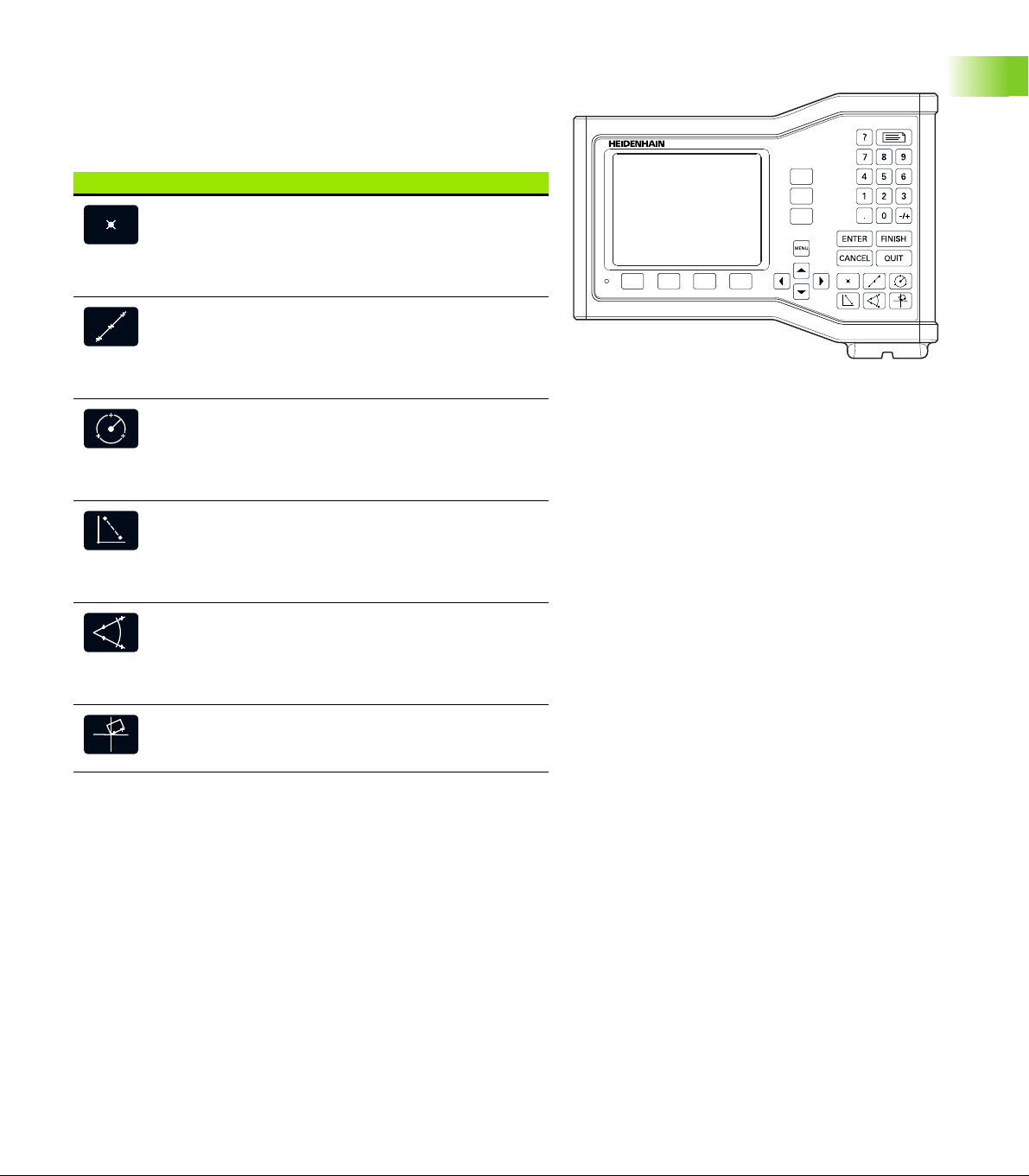
MEASURE keys Function
Measure point: Press the Point key once to
measure one point, or twice to use auto
repeat to measure a series of points. A
minimum of one data point is required to
measure a point.
Measure line: Press the Line key once to
measure one line, or twice to use auto repeat
to measure a series of lines. A minimum of
two data points are required to measure a
line.
Measure circle: Press the Circle key once to
measure one circle, or twice to use auto
repeat to measure a series of circles. A
minimum of three data points are required to
measure a circle.
Measure distance: Press the Distance key
once to measure one distance, or twice to
use auto repeat to measure a series of
distances. Two points are required to
measure a distance.
1.2 Basic Functions
ND 123 panel keys
Measure angle: Press the Angle key once to
measure one angle, or twice to use auto
repeat to measure a series of angles. Collect
a minimum of two data points, then press the
ENTER key on each leg of an angle.
Align part: Press the Skew key to
compensate electronically for non-square
part alignment on the primary axis.
ND 120 QUADRA-CHEK 21
Page 22
COMMAND keys Function
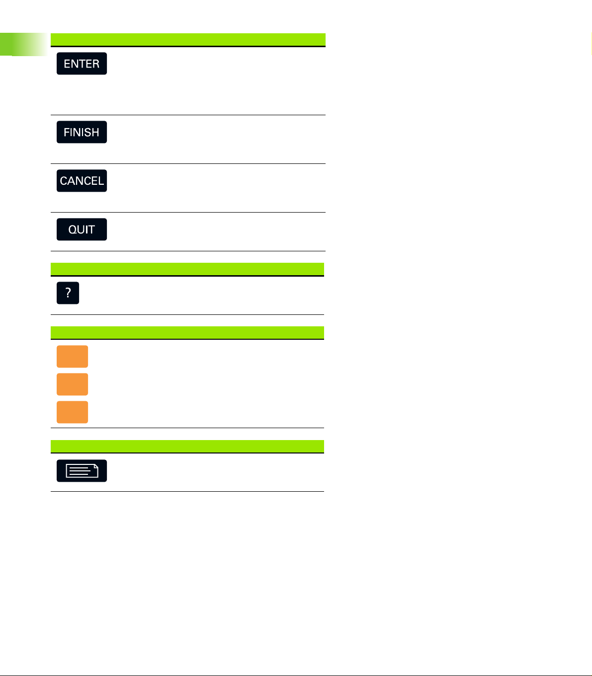
Enter data: Press the ENTER key to enter
points during feature measurements or to
enter values into configuration fields.
Pressing the ENTER key indicates that data
from a measurement or in a field is ready for
use.
Finish a measurement: Press the FINISH key
to complete a feature measurement. Pressing
the FINISH key a second time returns the user
to the DRO screen.
1.2 Basic Functions
HELP key Function
AXIS keys Function
SEND key Function
Delete data or features: Press the CANCEL
key to delete the last point entered, data in
configuration fields or any highlighted feature
from the feature list.
Quit current activity: Press the QUIT key to
abandon the current task and return to the
DRO screen or to exit the feature list.
Provide help: Press the Help key to display
help topics on the screen. Help topics explain
how to use the current function.
Zero an axis: Press the axis key to the right
of the desired axis to zero the axis position
value when establishing a zero datum.
Preset an axis or axes: Press one or more
axis keys to the right of the desired axis or
axes when presetting axis position values for
a new datum.
Transmit measurement results: Press the
Send key to transmit measurement data to a
computer.
22 1 Operation
Page 23
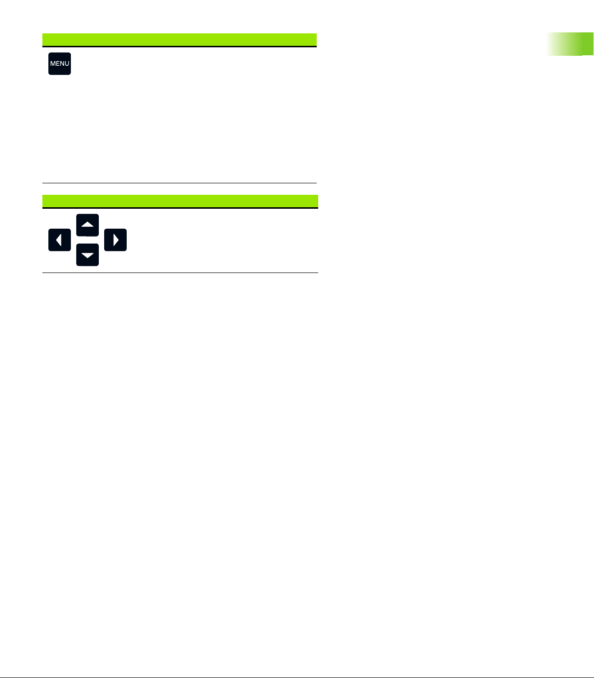
MENU key Function
Display soft key menus: Press the MENU key
to display the titles of menus above the soft
keys. Menus include:
Setup: Used by supervisors to configure
the operational characteristics of the
system.
Extra: Used by operators to conduct
measurements and send measurement
result data.
Clear: Used by operators to clear
measurement data and datums.
ARROW keys Function
Navigate menus and setup screen
data fields. The Up Arrow key is also
used to begin a feature construction
process.
1.2 Basic Functions
ND 120 QUADRA-CHEK 23
Page 24
Display modes and soft key layout
DRO screens display information in one of four operating modes:
DRO mode displays current positions of axes
Feature evaluation mode screens can be toggled between two
displays that show all measurement results and the data cloud of
collected points
Feature measurement mode displays feature type, points
collected and current positions of axes during measurements
Setup mode displays installation and setup screens
Soft keys change to support activities shown on the screens.
1.2 Basic Functions
Notice
Installation and setup screens and soft keys are described
later in Chapter 2: Installation, Setup and Specifications.
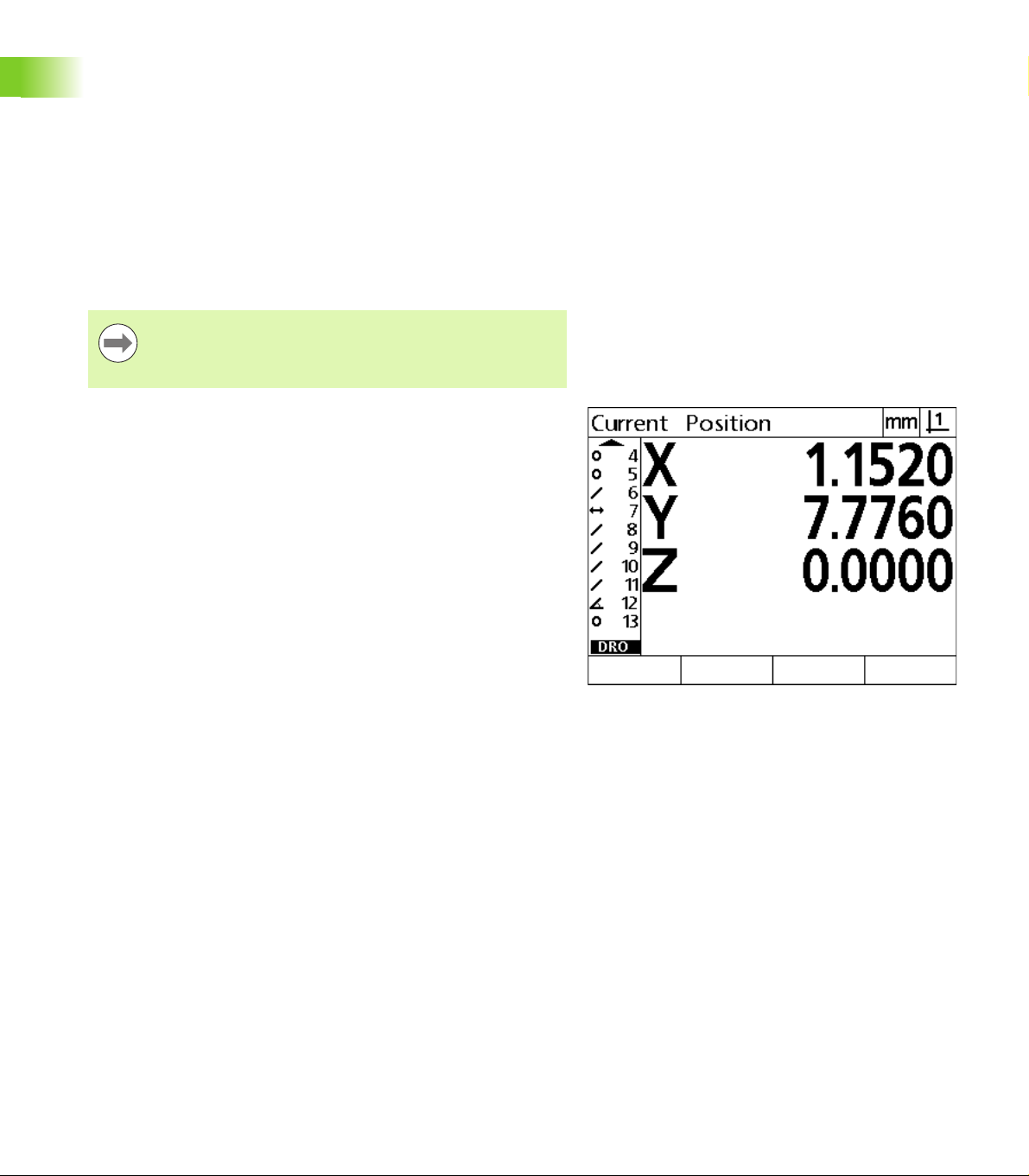
DRO mode screen
The DRO screen shows:
Feature list of measured features on the left side
Unit of measure and current datum in the upper right corner
The current positions of all axes
Part alignment status: a small rectangle over the axis letter indicates
that the part is aligned to a measurement axis (a skew was
performed)
DRO current position screen showing current axis
positions
24 1 Operation
Page 25
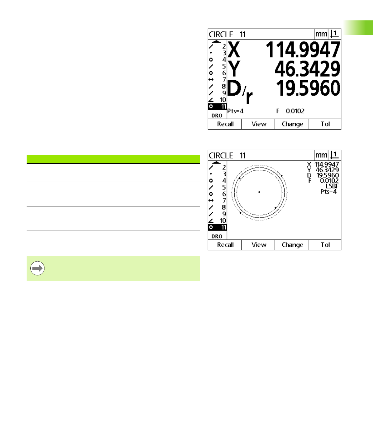
Feature evaluation mode screens and soft keys
The feature evaluation screens can be toggled between two displays
by pressing the View soft key to show:
Feature list of measured features on the left side
Unit of measure and current datum in the upper right corner
The feature type and number of the highlighted feature
Feature position
Geometric and dimensional values such as diameter, length or angle
Number of data points used to define the feature
Form error
Parent features used if the feature was constructed
An indication that the feature was created if applicable
Data cloud of collected data points used to define the feature
DRO soft keys Function
Recall Displays a different feature from the feature list
by specifying its feature number.
1.2 Basic Functions
Feature evaluation mode screen showing feature
values
View Toggles between the default screen showing
axis values and the screen showing data points
collected to define the feature.
Change Shows alternative fit algorithms for the current
feature type, such as LSBF (least squares best
fit) and ISO.
Tol Displays the alternative tolerances that can be
applied to the current feature.
Notice
Tolerances are discussed later in this chapter.
Feature evaluation mode screen showing data points
ND 120 QUADRA-CHEK 25
Page 26
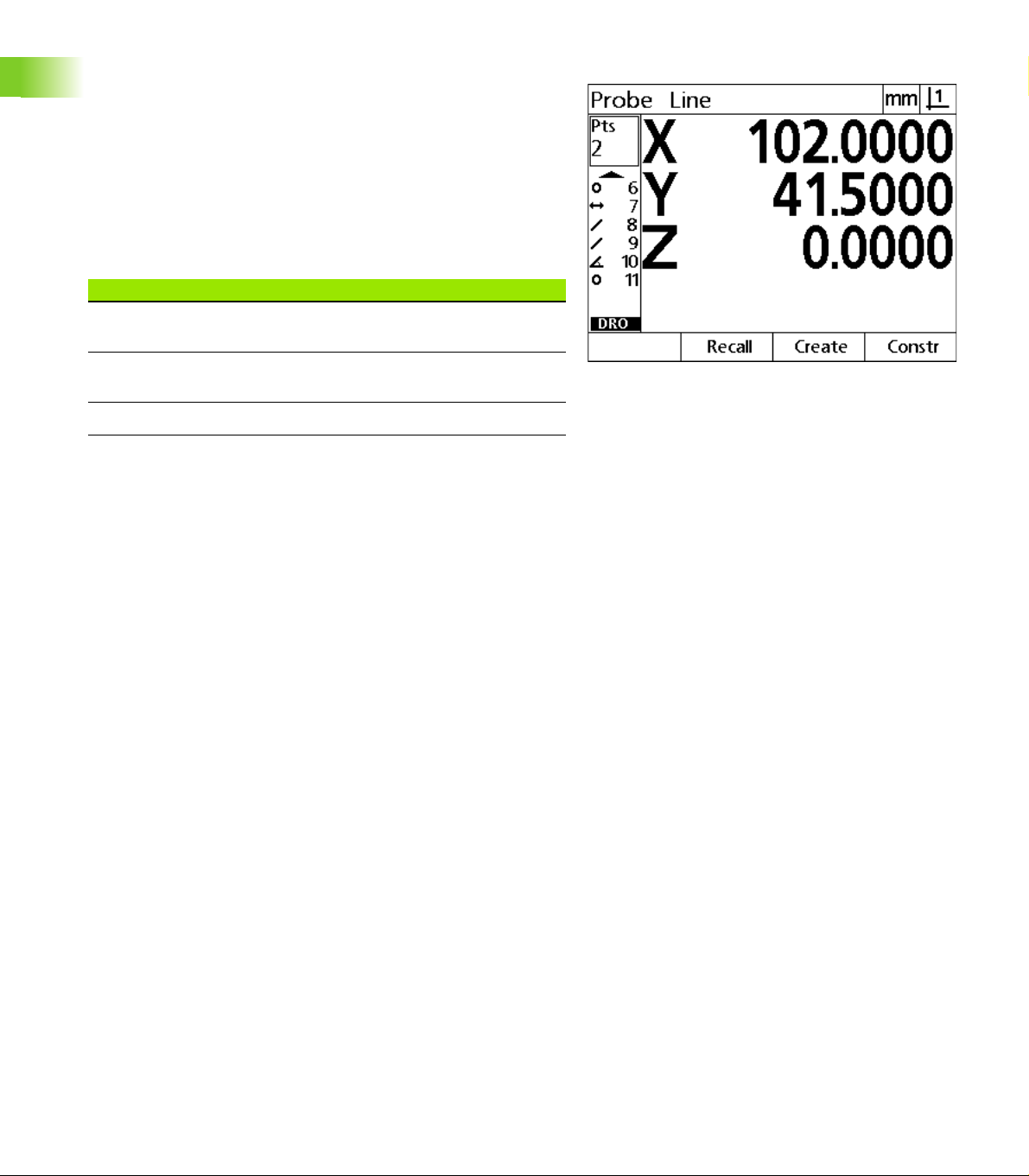
Feature measurement mode screen and soft keys
The feature measurement screen is displayed after initiating a feature
measurement by pressing a Measurement key and shows:
Feature list of measured features on the left side
Unit of measure and current datum in the upper right corner
The feature type being probed and the number of collected data
points
The current positions of all axes
DRO soft keys Function
1.2 Basic Functions
Recall Recalls the first parent feature of a new feature
construction.
Create Displays fields for entering data to create the
specified feature type.
Constr Initiates a new feature construction.
Feature measurement mode screen showing feature
type and points collected
26 1 Operation
Page 27
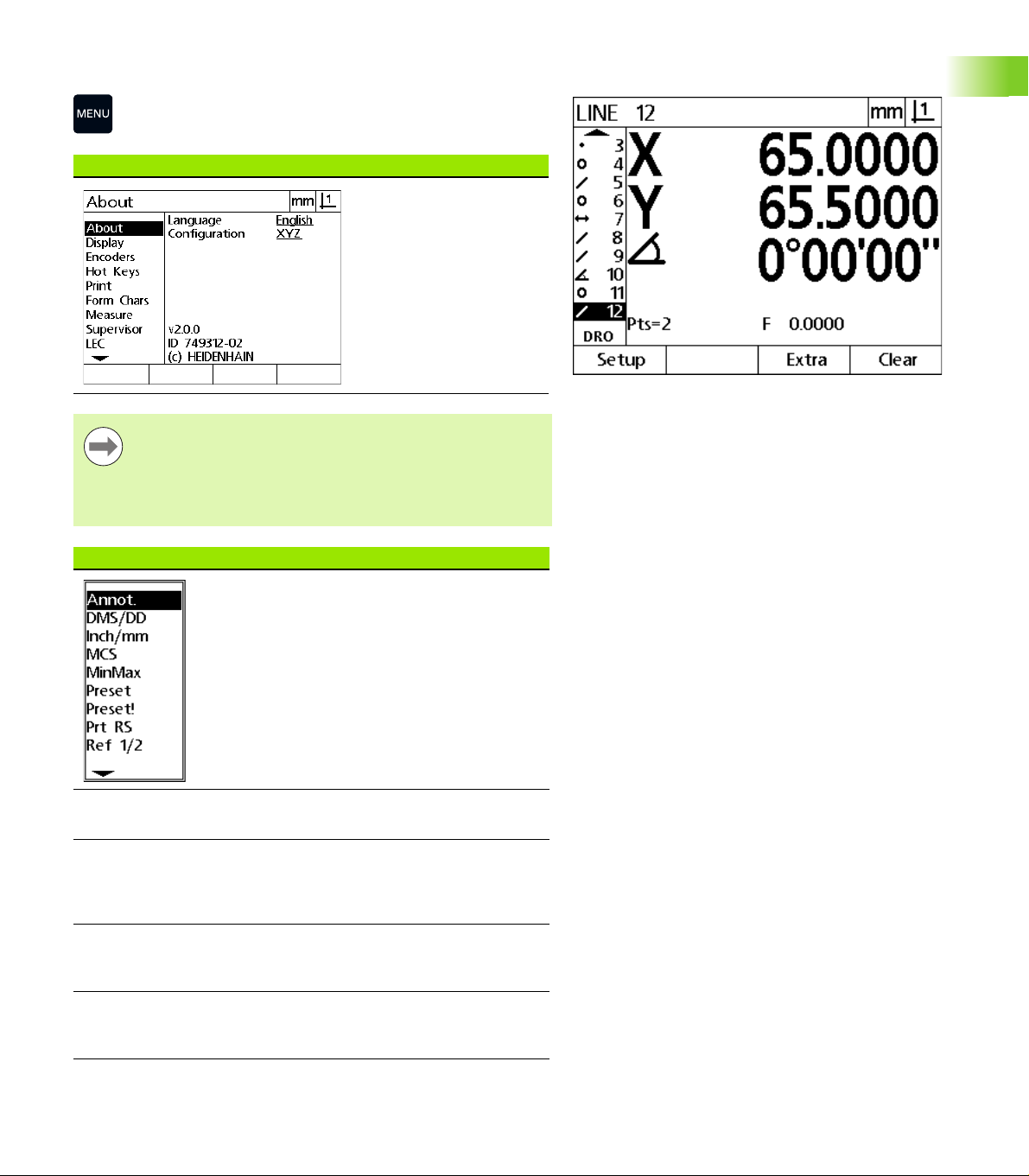
Menus
Press the MENU key to display menu titles over the soft keys at
the bottom of the LCD screen. Press a menu soft key to display
the corresponding menu screen. Menus include:
SETUP menu SETUP functions
Press the Setup soft key to
display the collection of
Setup screens used to
configure the DRO. Use of
the Setup menu is
explained in Chapter 2:
Installation, Setup and
Specifications.
Notice
Access to setup menu configuration data fields is
password restricted to supervisors and other technically
qualified personnel. Configuration mistakes can result in
serious measurement errors.
EXTRA menu EXTRA functions
Press the Extra soft key to
display the Extra pop-up
menu. The Extra menu is
used perform many
measurement and data
transmission functions.
Highlight a function and
then press the ENTER key.
Extra menu functions
include:
1.2 Basic Functions
Menu titles are displayed over soft keys at the bottom
of the LCD screen
Annot Toggles between forward
DMS/DD Toggles between the
Inch/mm Toggles between the
MCS Clears datums and re-
ND 120 QUADRA-CHEK 27
and backward annotation.
display of degrees,
minutes, seconds and
decimal degrees.
display of inches and
millimeters.
establishes machine
coordinates.
Page 28

EXTRA menu EXTRA functions
MinMax Collects and stores
Preset Sets the position of one or
Preset! Recalls the last preset
Prt RS Sends current data to the
1.2 Basic Functions
Send 2 Sends current X, Y data to a
Send 3 Sends current X, Y, Z/Q
minimum and maximum
values until the finish key
is pressed.
more axes to specified
values.
position.
RS-232 port.
computer.
data to a computer.
Send D Sends current diameter to
Send F Sends current form error to
Send L Sends current distance to a
Send Q Sends current Q-axis value
Send r Sends current radius to a
Send X Sends current X-axis value
Send Y Sends current Y-axis value
Send Z Sends current Z-axis value
Send < Sends current angle to a
Zero 2 Zeros X and Y axes.
Zero Q Zeros Q-axis protractor
a computer.
a computer.
computer.
to a computer.
computer.
to a computer.
to a computer.
to a computer.
computer.
value.
28 1 Operation
Page 29
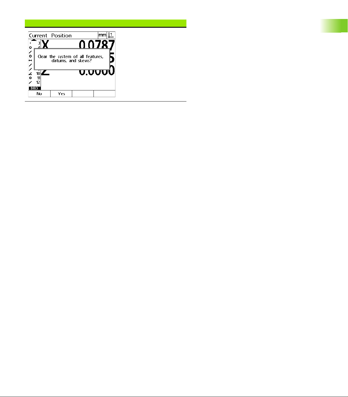
CLEAR menu CLEAR functions
Press the Clear soft key to
clear feature, datum and
part alignment data.
1.2 Basic Functions
ND 120 QUADRA-CHEK 29
Page 30
1.3 Preparing to Measure
Power-up
Switch on the product. The power switch is located on the rear of
the enclosure. After switching the power on, or after a power failure,
the power-up screen will be displayed. See "Initial power-up" on
page 19.
Press the ENTER key to advance from the power-up screen to the
DRO.
If the product was configured to establish a machine zero upon
powering up, a message will be displayed asking you to cross
reference marks or specify axis references manually.
Establish machine zero
1.3 Preparing to Measure
A repeatable machine zero is required for the DRO to apply the
calibration chart to the machine geometry correctly.
It is not recommended to use the machine without active
calibration. This would lead to unknown position errors.
Usually the calibration is based on referencing via reference marks on
the encoders. To establish the machine zero after power-up:
Move the stage to have the reference mark crossings recognized on
each axis.
If the machine zero is determined via hard stops:
Move the stage to the hard-stop reference position and press ENTER
on each axis.
30 1 Operation
Page 31

Select the desired annotation
Annotation determines the number of measurement points collected
for each feature type.
Forward annotation: Use forward annotation to require a
previously specified number of points for each feature type. When
using forward annotation, the number of required points is shown in
the top left corner of the screen. As points are entered, the number
of required points counts down. Since a fixed number of points is
required using forward annotation, the system automatically
completes the measurement and displays the feature after the last
required point is entered. It is not necessary to press the FINISH key
in forward annotation measurements to complete a measurement.
Backward annotation: Use backward annotation to allow the
operator to determine the number of points for each feature.
Backward annotation displays the total number of points collected
in the top left corner of the screen as they are entered. It is
necessary to press the FINISH key to complete backward annotation
measurements.
Toggle between forward and backward annotation
Press Menu>Extra>Annot>Enter
1.3 Preparing to Measure
ND 120 QUADRA-CHEK 31
Page 32

Align the part to a measurement axis
Accurate measurements require the part to be perfectly aligned along
a measurement axis. Misaligned parts result in cosine measurement
errors. Use the skew function to convert machine coordinates to part
coordinates and compensate for part misalignment. Measure a skew
each time a new part is mounted on the measuring system.
Measure a skew line by probing a straight edge of the part on a major
measurement axis. A minimum of two points is required for a line, but
probing more points will improve accuracy.
Notice
The alignment is performed on a part edge here as an
example. Part alignments can be made on part features
other than an edge. For example, a line constructed
between the centers of two holes could be aligned to a
1.3 Preparing to Measure
Perform a part alignment (Skew)
measurement axis if desired.
The skew alignment edge or line must be oriented within
45 degrees of the measurement axis.
Press the Skew key.
Probe a minimum of two points along the part edge.
In the example shown here, the part is aligned to the
X-axis by probing three points along the bottom edge
of the part.
Notice
The part could alternately have been aligned along a
vertical edge to the Y-axis.
Three points are probed to align the bottom edge of a
part to the X-axis
32 1 Operation
Page 33

Establish a datum
Establish a reference datum once the part is skewed. Two datums can
be created. Typically, datum 1 is a zero reference and used as an
absolute or primary datum, while datum 2 is used as an incremental or
temporary datum.
Datums can be set to zero or can be preset to specified values.
Two methods can be used to establish a datum:
Zero or preset the X and Y axes on a point or on the center point of
a circle
Zero or preset the X and Y axes on a point or on a center point
constructed from parent features
While the datum can be created from a probed point or from the
center point of a probed circle, it is more commonly created from a
point that has been constructed from important parent features, such
as the skew alignment line and a second part edge line. An example
of a datum created from a constructed point is shown below.
Notice
Constructions and the feature measurements necessary
for constructions are discussed in detail later in this
chapter. However, a brief example of constructions is
shown here to adequately cover the topic.
Probe skew and part edge lines for point construction
Probe a skew alignment line along the bottom of the part and probe a
line on the left side of the part. These lines will be used to construct a
datum point.
Perform skew part alignment to the X-axis on the bottom edge
Press the Skew key.
Probe 3 points along the bottom edge (points 1, 2
and 3).
Press the FINISH key to complete measuring the
skew line.
1.3 Preparing to Measure
Probe a line along the left edge
Press the Line key.
Probe 3 points along the left edge (points 4, 5 and 6).
Press the FINISH key to complete measuring the
A skew is performed along the bottom and a line is
probed on the left side
second line.
The skew and left edge lines will now be shown in the feature list on
the left side of the DRO screen. The point construction using these
parent features is shown next.
ND 120 QUADRA-CHEK 33
Page 34

Construct a datum point from line features
Construct a point from the skew line and the left edge line to create a
datum.
Press the Point key. The Probe Point screen will be
displayed.
Press Up Arrow>ENTER to start the construction and
select the line feature (2). The screen will change to
the Construct Point screen, feature 2 will be checked
and skew line feature 1 will become highlighted.
Press ENTER to check feature 1.
Press the FINISH key to complete the point
construction from the intersection of the two
checked parent line features.
1.3 Preparing to Measure
POINT key is pressed Features are selected Point is constructed
Zeroing the datum
Datums can be zeroed or preset. This example creates a zero
reference datum from a point feature.
Press the X and Y Axis keys to zero the point position.
Point is highlighted Point is zeroed as datum
34 1 Operation
Page 35

Presetting the datum
Datums can be zeroed or preset. This example creates a preset
reference datum from a point feature.
Press MENU>Extra>Preset>Enter to display the preset
screen.
Press the desired Axis key and enter the preset value
for the axis.
Press another Axis key if desired and enter the preset
value for that axis.
Press the FINISH key to preset the datum to the
specified values.
PRESET Selected from EXTRA menu Preset values are entered Point is preset as datum
1.3 Preparing to Measure
ND 120 QUADRA-CHEK 35
Page 36

1.4 Measuring Part Features
Part features
Features are measured by probing data points that characterize the
dimensional geometry of the part. For example, several points probed
around the circumference of a circle results in numeric and graphic
representations of the circle geometry. Throughout this manual, a
measured geometry is referred to as a feature and can alternately be
displayed numerically or graphically by pressing the View soft key.
There are several types of features and each has different dimensional
information. For example, a circle has a center point position and a
radius, a point has a position, and an angle has degrees.
1.4 Measuring Part Features
Feature displayed numerically Feature displayed graphically
Feature list
Each feature is added to the feature list when it is measured. The
feature list shows all features measured on the left side of the LCD
screen and is visible in DRO and measuring modes. Each feature is
identified by a number and an icon indicating its type (i.e. circle, line,
etc.). Up to 100 features can be added to the feature list. Use the
Arrow keys to scroll through the list. Highlight the desired feature to
recall or send the feature data to a computer. Select parent features
from the feature list to construct new features. Delete features using
the CANCEL key or by pressing the MENU key and then the Clear soft
key. In general, the user should delete old features, datums, and
skews from the feature list before each new measurement session.
Probing part features
Part features are probed with crosshairs.
Probing with crosshairs
Move the stage to position the crosshairs over the desired feature
point and press the ENTER key. The probed point will be added to the
points required for the feature.
36 1 Operation
Page 37

Measuring features
The ND 12x measures point, line, circle, distance and angle features.
To measure a feature using backward annotation (See "Select the
desired annotation" on page 31):
Press the desired feature Measurement key
Probe the required points
Press the FINISH key
Auto repeat
Use auto repeat to measure several features of the same type (such
as a series of circles). Press the desired feature Measurement key twice
to activate auto repeat. For example, press the Circle Measurement
key twice to measure a series of circles. When auto repeat is selected,
the Probe feature screen becomes the Probe features screen. For
example, the Probe Circle screen becomes probe Circles screens as
shown below.
1.4 Measuring Part Features
Probe Circle screen Probe Circles screen
Use auto repeat and forward annotation to speed up repetitive
measurements. For example, the measurement of a dozen circles
requires the user to press the Circle Measurement key before
measuring each circle and press the FINISH key for each
measurement. The same measurements using auto repeat and
forward annotation requires the user to press the Circle Measurement
key twice before and the FINISH key once after measuring all 12
circles. Pressing the FINISH key turns off auto repeat.
Notice
Examples of measurements are shown in the next few
pages and will use crosshairs to probe points on the 2-D
demo part shipped with each unit.
ND 120 QUADRA-CHEK 37
Page 38

Measuring points
Points are the simplest features to measure. Only one point is required
to define the location of a point. A maximum of 100 points can be
probed and will be averaged by the system to measure a single point.
Press the Point Measurement key. The Probe Point
screen will be displayed. Press the key twice to
measure a series of points using auto repeat.
Move the stage to position the crosshairs over the
desired point location and press the ENTER key.
Press the FINISH key to complete the measurement.
The point position will be shown and the point feature
will be added to the feature list.
1.4 Measuring Part Features
A point is probed on the part
The point position is shown and the point feature is
added to the feature list
38 1 Operation
Page 39

Measuring lines
A minimum of 2 points are required to measure a line. A maximum of
100 points can be probed and will be processed by a fit algorithm to
define the line.
Press the Line Measurement key. The Probe Line
screen will be displayed. Press the key twice to
measure a series of lines using auto repeat.
Move the stage to position the crosshairs over an end
point of the line and press the ENTER key.
Move the stage to position the crosshairs over the
other end point of the line and press the ENTER key.
Press the FINISH key to complete the measurement.
The line position and angle will be shown and the line
feature will be added to the feature list.
Press the Change soft key to change the line fit
algorithm if desired.
Line fit algorithms include:
LSBF: Fit determined by minimizing the sum of the squared point
deviations from the form fit.
ISO: Fit determined by minimizing the form deviation.
A line is probed on the part
1.4 Measuring Part Features
The line position and angle are shown and the line
feature is added to the feature list
ND 120 QUADRA-CHEK 39
Page 40

Measuring circles
A minimum of 3 points are required to measure a circle. A maximum
of 100 points can be probed and will be processed by a fit algorithm to
define the circle.
Press the Circle Measurement key. The Probe Circle
screen will be displayed. Press the key twice to
measure a series of circles using auto repeat.
Move the stage to position the crosshairs over a point
on the circumference of the circle and press the ENTER
key.
Move the stage to position the crosshairs over two
other points evenly distributed around the
circumference, pressing the ENTER key to collect each
point.
Press the FINISH key to complete the measurement.
The circle position and diameter will be shown and
the circle feature will be added to the feature list.
1.4 Measuring Part Features
Press the Left or Right Arrow key to toggle the
display between Diameter and Radius if desired.
Press the Change soft key to change the circle fit
algorithm if desired.
Circle fit algorithms include:
LSBF: Fit determined by minimizing the sum of the squared point
deviations from the form fit.
ISO: Fit determined by minimizing the form deviation.
Outer: Yields the biggest circle.
Inner: Yields the smallest circle.
A circle is probed on the part
The circle position and diameter are shown and the
circle feature is added to the feature list
40 1 Operation
Page 41

Measuring distances
Two points are required to measure a distance.
Press the Distance Measurement key. The Probe
Distance screen will be displayed. Press the key
twice to measure a series of distances using auto
repeat.
Move the stage to position the crosshairs over the
first of the two points and press the ENTER key.
Move the stage to position the crosshairs over the
second of the two points, and press the ENTER key.
Press the FINISH key to complete the measurement.
The X, Y and vector distances will be shown and the
distance feature will be added to the feature list.
When a Z-axis is used, press the Left or Right Arrow
key to toggle the display between the vector distance
(L) and the Z height if desired. Z-axis height is not
used in the calculation of vector distance.
A distance is probed on the part
1.4 Measuring Part Features
The X, Y and vector distances are shown and the
distance feature is added to the feature list
ND 120 QUADRA-CHEK 41
Page 42

Measuring angles
A minimum of 4 points evenly divided on two legs of an angle are
required to measure an angle. A maximum of 100 points can be
probed on the two angle legs. Once the minimum two points are
probed on each angle leg, additional points can be distributed between
the two legs in any proportion. For example, the first leg could be
defined by 4 points, and the second by 8.
Press the Angle Measurement key. The Probe Angle
screen will be displayed. Press the key twice to
measure a series of angles using auto repeat.
Move the stage to position the crosshairs over a
minimum of two points evenly distributed on one
angle leg, pressing the ENTER key to collect each
point.
Press the FINISH key to complete the measurement
of the first leg.
Move the stage to position the crosshairs over a
1.4 Measuring Part Features
minimum of two points evenly distributed on the
second angle leg, pressing the ENTER key to collect
each point.
Press the FINISH key to complete the angle
measurement. The angle and angle vertex position
will be shown. The angle feature and two angle leg
features will be added to the feature list.
Press the Change soft key to change the angle type if
desired.
Slot features form an angle (
ø) on the part
Angle types include:
The two legs of an angle are probed on the part
INCLD: Included angle (A1).
360-A1: 360 degrees - included angle.
180+A1: 180 degrees + included angle.
180-A1: 180 degrees - included angle
INCLD (A1) 360 - A1 180 + A1 180 - A1
The angle and angle vertex position are shown. The
angle and angle legs are added to the feature list
42 1 Operation
Page 43

1.5 Creating Part Features
Created features
The Create Part Feature function can be used to create features that
are not found on the part geometry. These features can be used as
reference points for inspection purposes. For example, in order to
measure a feature that is referred to a point off the part geometry, the
user could create the reference point.
Users can create points, lines, circles, distances, angles, and part
skews. Created features are the same as probed features except that
the created features are geometrically perfect, so form error and
tolerance values do not apply.
Created features are not the same as constructed features, which are
discussed in the next section of this chapter. Created features are
defined by the user. For example, to create a circle, the user defines
the location of the center point and the diameter or radius.
Constructed features are built from previously measured or created
parent features. For example, the user could construct a line between
two or more points in the feature list. Constructed features can have
form errors and tolerance values.
Creating features
The method of creating a feature is identical for all feature types. To
create a feature:
Press the desired feature Measurement key
Press the Create soft key
Enter the required feature data
Press the FINISH key
1.5 Creating Part Features
Notice
An example of creating a feature is shown on the next
page.
ND 120 QUADRA-CHEK 43
Page 44

Example of creating a feature
In this example, a circle is created:
Press the CIRCLE MEASUREMENT key to display the
Probe Circle screen.
Press the Create soft key to display the Create data
entry screen.
Enter the circle position and diameter (or radius)
values.
Press the FINISH key. The new circle will be shown on
the screen and added to the feature list.
1.5 Creating Part Features
Circle Measurement key is pressed Circle position and diameter values are
entered
New circle is shown in the feature list
44 1 Operation
Page 45

1.6 Constructing Part Features
Constructed features
New features can be constructed from probed, created, or other
constructed features in the features list. Constructions are frequently
used to perform skew alignments, set datums and measure
relationships between parent features.
Users can construct points, lines, circles, distances, angles, and part
skews. Constructed features are the same as probed features. They
can have form errors and tolerances can be applied.
Notice
If a construction is requested that does not include the
required parent features or is not supported, an error
message is displayed indicating an “Invalid construction”.
Constructing features
The method of constructing a feature is identical for all feature types.
To construct a feature:
Press the desired feature Measurement key
Press the Constr soft key or the Up Arrow key
Highlight a required parent feature, then press the ENTER key to
select it
Continue highlighting and selecting parent features until all the
required features are selected
Press the FINISH key
1.6 Constructing Part Features
Notice
An example of constructing a feature is shown on the next
page.
ND 120 QUADRA-CHEK 45
Page 46

Example of constructing a feature
In this example, a new point feature is constructed from two parent
circle features:
Press the Point Measurement key.
Press the Constr soft key or press the Up Arrow key to highlight the
last feature in the feature list. If the last feature in the feature list will
not be one of the parent features, press the Up Arrow key until the
first parent feature is highlighted. In this example, the first parent
circle feature is at the bottom of the feature list.
Press the ENTER key to select the highlighted feature. A checkmark
will appear at the feature location in the list.
1.6 Constructing Part Features
Point Measurement key is pressed First circle feature is highlighted First circle feature is selected as a parent
feature
Continue highlighting and then selecting features until all the
required parent features are selected. In this example, the second
circle feature is highlighted and selected.
Press the FINISH key to construct the new feature. The new point
feature is shown at the bottom of the feature list.
Second circle feature is highlighted Second circle feature is selected as a
parent feature
FINISH key is pressed to complete
constructing the new point feature
46 1 Operation
Page 47

Press the View soft key to show a graphic image of the feature
construction. In this example the image shows that the Int 1 point
feature was constructed at the top intersection of the two circle
circumferences.
Press the Change soft key to show alternative point features that can
be constructed from the two parent circle features.
Press the desired construction alternative soft key to change the
feature construction type. In this example, the Mid Pt point feature
was selected, and the point is constructed at the mid point between
the two circle center points.
View soft key is pressed to show graphic
image of constructed feature
Change soft key is pressed to show
alternative constructions
More feature construction examples
A collection of some typical feature constructions are shown here
graphically as examples. Many more constructions are possible.
Invalid construction requests will initiate an error message.
Construction Parent features Graphic
Point Two lines: intersection
Point Line and circle: intersection
Point Two circles: intersection
Point Two points: mid point
Point feature type is changed from Int 1
1.6 Constructing Part Features
to Mid Pt
ND 120 QUADRA-CHEK 47
Page 48

Construction Parent features Graphic
Point Point and circle: mid point
Point Distance and point: offset
Point Circle: center point
Point Line and point: perpendicular
1.6 Constructing Part Features
Point Line and datum: perpendicular
Line Points: Best fit
Line Line and circle: perpendicular
Line Two lines: bisector
Line Line and distance: offset
Circle Multiple circles: best fit
48 1 Operation
Page 49

Construction Parent features Graphic
Circle Circle and distance: offset
Distance Two points: point to point
Distance Circle and circle: center to center
Distance Point and line: perpendicular
Angle Two lines: vertex
1.6 Constructing Part Features
ND 120 QUADRA-CHEK 49
Page 50

1.7 Tolerances
Feature tolerances
The following tolerances are available.
Feature type To l e r a n c e
Point Bidirectional position
1.7 Tolerances
Point True position
Line Bidirectional position
Line True position
Line Straightness
Line Perpendicularity
Line Parallelism
Line Angle
Circle Bidirectional position
Circle True position
Circle LMC: Least material condition
Circle MMC: Maximum material condition
Circle Roundness
Circle Concentricity
Circle Runout
Distance Width
Angle Angle
50 1 Operation
Page 51

Applying tolerances
The method of applying tolerances is identical for all feature types. To
apply a tolerance:
Highlight a feature in the feature list using the Arrow keys.
Press the Tol soft key to display the tolerance soft keys.
Press the soft key corresponding to the desired tolerance type, such
as runout for a circle. A new screen will be displayed containing data
fields for nominal and tolerance values.
Enter the nominal and tolerance values and then press the FINISH
key to display the tolerance results. Press the FINISH key again to
return to the DRO screen.
Measurements that pass tolerance tests are indicated by a checkmark
in the tol soft key box. Measurements that fail are indicated by a
crossed circle in the Tol soft key box and by outlined characters in the
DRO screen.
1.7 Tolerances
Passed tolerance indicated by
checkmark in Tol soft key box
Notice
An example of applying a tolerance is shown on the next
page.
Failed tolerance indicated by crossed
circle in Tol soft key box and outline
characters
ND 120 QUADRA-CHEK 51
Page 52

Example of applying a tolerance
In this example, a form tolerance (roundness) is applied to a circle
feature:
Use the Arrow keys to highlight the desired feature in the feature list.
In this example, the circle feature is highlighted.
Press the Tol soft key to display circle feature tolerance alternatives:
Pos (Position)
Form
1.7 Tolerances
Runout
Con (Concentricity)
Press the soft key corresponding to the desired tolerance type to
display the data entry screen. In this example, the Form soft key was
pressed and the data entry screen for specifying the roundness
tolerance is displayed. Initially, the tolerance data field (Tol. Zone)
contains the measured deviation from ideal roundness.
Circle feature is highlighted using Arrow
keys
52 1 Operation
Tol soft key is pressed to display
tolerance soft keys
Form soft key is pressed to display the
tolerance data entry screen
Page 53

Enter the desired nominal tolerance values into the data fields
provided. In this example of circle form tolerance, only the
roundness tolerance field is provided, and a tolerance of 0.15 is
entered.
Press the FINISH key to display the tolerance result. The tolerance
and actual values will be displayed. In this example, the tolerance
value was greater than the actual value and the tolerance passed. A
checkmark is shown to indicate a passed test.
Press the FINISH key again to return to the DRO screen. The
checkmark is shown again in the Tol soft key box.
1.7 Tolerances
The form tolerance is entered The FINISH soft key is pressed to display
the tolerance test result
The FINISH key is pressed to return to
the DRO screen
ND 120 QUADRA-CHEK 53
Page 54

1.8 Reporting
Reporting
Reports of measurement results can be sent to a computer over a
USB-to-Serial connection.
Notice
1.8 Reporting
Report types include:
Report type Report content
Display The data displayed on the DRO screen is sent as
Report All feature measurement data is sent in tabular
Report content and format are specified in the Print setup
screen discussed in Chapter 2: Installation and
Specifications.
one row for each axis.
form without tolerance data.
Tol Rpt All tolerance data is sent in tabular form. Feature
CSV All feature measurement data is sent in as comma
Tab All feature measurement data is sent in as tab
None No data are sent.
measurement data are not sent.
separated variables without tolerance data.
separated variables without tolerance data.
Sending reports
Reports can be sent at any time. To send a report:
Press the feature Send key.
54 1 Operation
Page 55

1.9 Error Indications
Scale errors
Only input encoder scale errors are reported. Scale errors are indicated
by the presence of graphic bars across the DRO screen instead of
numbers. Scale errors can be caused by a few conditions shown in
this table:
Possible cause Corrective action
Damaged encoder
reader head
Repair or replace the encoder.
Misaligned
encoder reader
head
Electrical noise on
the encoder input
Stage (encoder)
velocity too high
Faulty encoder
input connection
Recalibrate the reader head.
Verify that the earth ground provided by the
power source is in good condition and is
connected to the power system ground.
Verify that the encoder cable is shielded
and that the shield is connected to ground
at the DRO end.
Verify that the reader head is not generating
electrical noise.
Restrict stage velocity. If the velocity
required for error-free operation is slow,
recalibrate the reader head.
Repair or replace the encoder cable or seek
the assistance of your HEIDENHAIN
distributor.
1.9 Error Indications
ND 120 QUADRA-CHEK 55
Page 56

1.9 Error Indications
56 1 Operation
Page 57

Installation, Setup and Specifications
Page 58

2.1 Installation, and electrical
connection
Items supplied
Display Unit
Power cord
Installation Instructions
Tilt / Swivel Assembly
Accessories
Tilting base (ID 625491-01)
Mounting arm (ID 382893-01)
Mounting frame (ID 647702-01)
QUADRA-CHEK Wedge communication software (ID 709141-01)
2.1 Installation, and electrical connection
58 2 Installation and Specifications
Page 59

Installation
The DRO may be installed by attaching the unit to a tilting base, a
mounting arm or a mounting frame. Refer to the instructions provided
with an accessory for additional information.
Do not mount in a position that makes it difficult to access
the power switch or power cable.
Tilting base (ID 625491-01) (optional)
A locking handle is used to secure the DRO from below onto a tilting
base.
Mounting arm (ID 382893-01) (optional)
A locking handle is used to secure the DRO from below onto a
mounting arm.
2.1 Installation, and electrical connection
ND 120 QUADRA-CHEK 59
Page 60

Mounting frame (ID 647702-01) (optional)
A mounting frame is used to secure the DRO for panel mount
applications.
2.1 Installation, and electrical connection
60 2 Installation and Specifications
Page 61

Electrical connection
Electrical requirements
Power input: AC 100 V ... AC 240 V (–15 % to +10 %)
50 Hz ... 60 Hz (±2 %)
max.54 W
Replacable fuse: T500 mA / 250 V, 5 mm x 20 mm
Environmental conditions
The ND 12x meets standards for normal environmental conditions.
Operating temperature: 0° C ... 45° C
Storage temperature: -20° C ... 70° C
Protection (EN 60529) IP40, IP54 front panel
Weight: 2.6 kg
Power connector wiring
L: Line voltage (brown)
N: Neutral (blue)
Protective conductor (ground) terminal (green/yellow)
3-conductor (grounded)
Minimum diameter: 0.75 mm
Maximum length: 3 meters
Warning! Risk of electrical shock
A risk of electrical shock exists if this product is not
properly grounded.
To avoid the hazard, always use a 3-conductor (grounded)
power cord and ensure the ground is properly wired to the
building installation.
2
Power connector wiring
2.1 Installation, and electrical connection
Warning! Risk of fire
A risk of fire exists if a power cord not meeting minimum
specifications is used.
To avoid the hazard, always use power cords that meet or
exceed the minimum listed specifications.
ND 120 QUADRA-CHEK 61
Page 62

Replacing a fuse
Warning! Risk of electrical shock
When replacing a fuse it is possible to touch hazardous live
parts.
To avoid the hazard, always power off the unit and
disconnect the power cable.
Notice
Use only replacement fuses meeting rated specifications
to avoid damage to the product.
Power-off the DRO
Disconnect the power cable from the source of power
Press the fuse holder release until the retaining mechanism is
disengaged
Remove the fuse holder and replace the fuse
Re-insert the fuse holder and gently press until the retaining
mechanism is engaged
2.1 Installation, and electrical connection
62 2 Installation and Specifications
Page 63

Connecting encoders
1
3
2
This product can be used with HEIDENHAIN linear, and rotary
encoders that provide digital TTL level signals.
The connecting cable must not exceed 30 meters in length.
The encoder connector locations are:
1 X-axis
2 Y-axis
3 Z/Q-axis
Connect the axis encoder tightly to it’s connector. An input label is
provided near the connector.
Pin layout for encoder inputs:
D-sub connector 9-pin Assignment
1N/C
2U
3
a1
Encoder axis connectors
Encoder axis connector pins
4U
a2
5
60 V (U
7 + V (U
8U
)
n
)
P
a0
9
2.1 Installation, and electrical connection
ND 120 QUADRA-CHEK 63
Page 64

Connecting a computer
1
The USB (type B) (1) port can be used to send measurement result
data to a computer. Settings data can be sent and received from a
computer using Hyperterminal or a similar serial communication
program.
Notice
The USB driver for virtual COM-Port is required for
communication between the DRO and a computer. The
driver and installation instructions can be downloaded
from www.heidenhain.de
To connect a computer:
Verify that the product is off.
Connect a computer USB (type A) port to the product’s USB (type
B) port (1) using a USB (type A) to USB (type B) cable.
Apply power to the DRO.
Launch the computer application that will be used to communicate
with the DRO, and configure the communication properties of the
COM port to match those of the DRO. Hyperterminal is used in this
manual. See "Connecting to Hyperterminal" on page 65.
Bits per second 115,200
Data bits 8
Parity None
2.1 Installation, and electrical connection
Stop bits 1
Flow control Hardware
USB (Type B) connector
Pin layout for USB inputs:
USB (type B) Assignment
1+5 V
2 Data (-)
3 Data (+)
4 GND
64 2 Installation and Specifications
USB (type B) connector pins
Page 65

Connecting to Hyperterminal
Hyperterminal or a similar serial communication application is required
to send and receive settings data and can be used to receive
measurement results.
To connect to Hyperterminal:
Open Hyperterminal on the computer. The New Connection
window is displayed.
In the New Connection window enter a filename in the Name: field,
select an icon and click OK.
In the Connect To window, select the communications port being
used by the DRO from the Connect using: drop-down menu and
click OK.
In the COM Properties window select the Port Settings to match the
DRO port settings and click OK.
Enter a filename, select an icon and click OKSelect the communications port Select the Port Settings and click OK
2.1 Installation, and electrical connection
ND 120 QUADRA-CHEK 65
Page 66

2.2 Software setup
The operating parameters must be configured prior to using the DRO
for the first time, and any time part measurement, reporting or
communication requirements change. Day to day use of the product
does not require reconfiguration of software settings.
Notice
Parameter changes made in any of the setup screens can
change the operation of the DRO. For this reason, setup
parameters are password-protected. Only qualified
2.2 Software setup
Software can be configured manually using the Setup menu screens,
or automatically by loading a settings file saved after a previous setup
session. Settings files are loaded from a computer over a USB-toSerial connection.
Parameters configured in setup screens will be retained until:
The data-backup battery is changed
The data and settings are cleared by maintenance personnel
Parameters are changed using the Setup menu screens
Certain software upgrades are performed
Previously saved settings files are loaded
personnel should be given password access to setup
screens. The unlocking of password-protected setup
functions is described on page 72.
66 2 Installation and Specifications
Page 67

Setup menu
123
Most operating parameters are configured using screens and data
fields accessed from the Setup menu. Highlighting Setup menu items
on the left side of the setup screen displays the corresponding setup
parameter data fields and choice fields on the right side of the screen.
1 Setup menu item: Setup screen name
2 Setup data field: Setup data are entered
3 Setup choice field: Setup choices are made
The Setup menu is easy to use:
Press the MENU key and then press the Setup soft key.
Navigate up or down in the menu to highlight the desired menu item
using the Up/Down Arrow keys.
Navigate from the menu (left side) to the setup fields (right side)
using the Left/Right Arrow keys.
Navigate up or down to highlight the desired data or choice field
using the Up/Down Arrow keys.
Enter setup data using the Numeric Keypad, or choose a setup
parameter choice from soft key selections or list. shown when the
field is highlighted.
Press the FINISH key to save the entry and return to the Setup
menu.
Press the FINISH key again to return to the DRO.
An example of using the Setup menu to enter the supervisor
password is shown on the next page.
2.2 Software setup
Setup screen menu items, data fields and choice
fields
ND 120 QUADRA-CHEK 67
Page 68

Setup example: entering the supervisor password
Critical setup parameters are password-protected. Only qualified
personnel should be given password access to setup screen
parameters. In this example, the Setup menu is navigated to the
Supervisor screen and the supervisor password is entered.
To enter the supervisor password:
Press the MENU key to display the menu soft keys.
Press the Setup soft key to display the Setup menu.
Navigate up or down in the menu to highlight the Supervisor menu
item using the Arrow keys.
2.2 Software setup
The MENU key pressed to display the
menu soft keys
Navigate from the menu to the Password setup field using the
The Setup soft key is pressed to display
the Setup menu
Right Arrow key.
Enter the supervisor password using the Numeric Keypad.
The right Arrow key is used to highlight
the Password data field
Press the FINISH key to save the password and return to the Setup
The supervisor password is entered
using the Numeric Keypad
menu.
Press the FINISH key to return to the DRO.
The Arrow keys are used to highlight the
Supervisor menu item
The FINISH key is pressed to save the
password and return to the Setup menu
68 2 Installation and Specifications
Page 69

Order of setup
The setup software is contained on up to 18 screens, depending on
the hardware configuration. It is possible that not all the setup screens
described in this chapter are active in your system. Disregard screen
descriptions that do not apply to your DRO.
The initial setup tasks should be performed in the order listed here.
Instructions are presented in this order on subsequent pages.
Initial setup tasks Setup screens
1: Language selection, axis configuration and product version information About
2: Supervisor password entry Supervisor
3: Encoder configuration Encoders and Misc
4: Loading settings data (instead of manual setup) Supervisor
5: Stage squareness calibration Squareness
6: Error correction LEC, SLEC or NLEC screen
7: Measurement scaling for parts that expand or shrink Scale factor
8: Measurement configuration Measure
9: Display formatting Display
The additional setup tasks can be performed in any order.
Remaining setup tasks Setup screens
Hot key assignments Hot keys
Print formatting Print and Form characters screens
Setup configurations can be saved to a computer using USB-to-Serial
connection.
Saving settings Setup screens
Saving settings data Supervisor
2.2 Software setup
ND 120 QUADRA-CHEK 69
Page 70

Language selection and product version
The About screen contains selections for changing the language of
text displayed on the screen, included in transmitted data and printed
on reports. Product software and hardware information is also
provided on the About screen.
To select a language:
Press MENU>Setup to display the Setup menu and highlight the About
menu item.
Highlight the Language choice field.
Press the List soft key to display the list of languages.
Highlight the desired language and press the ENTER key.
2.2 Software setup
Highlight the About menu item Highlight the Language choice field Highlight a language and press the ENTER
key
Press the FINISH key to save the language and return to the Setup
menu.
Notice
Language selection can also be made by pressing the Send
key while the startup screen is displayed.
70 2 Installation and Specifications
Page 71

Axis configuration
The ND 122 supports a two axes configuration, the ND 123 supports
two and three axes configurations.
To select a configuration:
Press MENU>Setup to display the Setup menu and highlight the About
menu item.
Highlight the Configuration choice field.
Press a soft key to select the desired configuration.
Highlight the About menu item Highlight the Configuration choice field Press a soft key to select a configuration
Press the FINISH key to save the configuration and return to the
Setup menu.
2.2 Software setup
ND 120 QUADRA-CHEK 71
Page 72

Supervisor password and program unlocking
The Supervisor screen contains the Password data field.
Most setup parameters are password-protected and setup can only be
performed after the password is entered. To enter the supervisor
password:
Press MENU>Setup to display the setup menu and then highlight the
Supervisor menu item.
Highlight the Password data field.
Enter the supervisor password.
2.2 Software setup
Highlight the Supervisor menu item Highlight the Password data field Enter the password
72 2 Installation and Specifications
Page 73

Sending and receiving settings data
The Supervisor screen contains tools for sending and receiving
configuration settings data. This eliminates the need to configure the
DRO manually using the setup screens. The settings data also
contains any error correction data that existed when the settings data
was saved to a computer. Settings data can be sent to or received
from a computer using Hyperterminal or a similar serial
communications application. Hyperterminal is used in this manual.
To send settings data to a computer:
Establish communication between the DRO and the computer. See
"Connecting a computer" on page 64.
Open and connect to Hyperterminal. See "Connecting to
Hyperterminal" on page 65.
In Hyperterminal, click Transfer>Capture Text... The Capture Text
window is displayed.
In the Capture Text window, enter a location and filename for
sending settings to.
Click Start.
2.2 Software setup
Click Transfer>Capture Text... Enter a location and filename Click Start
On the DRO press MENU>Setup to display the Setup menu.
Use the Arrow keys to highlight the Supervisor menu item.
Highlight the Password data field, enter the password then press
the ENTER key.
ND 120 QUADRA-CHEK 73
Page 74

Press the Send soft key. A pop-up window appears requesting
confirmation.
Press the Yes soft key to confirm sending settings.
Press the OK soft key.
2.2 Software setup
Press the Send soft key Press the Yes soft key Press the OK soft key
In Hyperterminal, click Transfer>Capture Text>Stop. The settings
have been saved to the location and text file specified in the Capture
Text window.
74 2 Installation and Specifications
Page 75

To receive settings data from a computer:
Establish communication between the DRO and the computer. See
"Connecting a computer" on page 64.
Open and connect to Hyperterminal. See "Connecting to
Hyperterminal" on page 65.
On the DRO press MENU>Setup to display the Setup menu.
Use the Arrow keys to highlight the Supervisor menu item.
Highlight the Password data field, enter the password then press
the ENTER key.
Press the Receive soft key. A pop-up window appears requesting
confirmation.
Press the Yes soft key to confirm receiving settings. A pop-up
window appears notifying to “Send settings data now...”.
In Hyperterminal, click Transfer>Send Text File...
2.2 Software setup
Press the Receive soft key Press the Yes soft key Click Transfer>Send Text File...
Select the settings file to send to the DRO and click Open. A pop-up
window is displayed on the DRO verifying “Receiving settings
data...”.
A pop-up will notify “The settings have been successfully received.
Reboot the system.” Reboot the DRO by powering-off the unit then
powering-on.
ND 120 QUADRA-CHEK 75
Page 76

Encoder configuration
The Encoders and Misc screens contain data and choice fields for
configuring the encoders.
Encoders screen
The Encoders screen configuration fields include:
Axis selection
Encoder resolution
Reference mark selection
Machine zero offset (MZ Cnts)
2.2 Software setup
Reversing encoder count direction
Units of measure
To configure encoder settings in the Encoders screen:
Press MENU>Setup to display the Setup menu and then highlight the
Encoders menu item.
Highlight the Axis choice field and then press a soft key to select the
desired axis.
Highlight the Res data field and then enter the encoder resolution in
the units shown in the Units choice field.
Encoders menu item is highlighted Press an axis soft key Enter the encoder resolution
76 2 Installation and Specifications
Page 77

Highlight the Ref Marks choice field and then press the List soft key
to display the reference mark choices. Highlight the required
encoder reference mark type and press the ENTER key.
Notice
Reference marks must be used if SLEC or NLEC error
correction will be performed later. Error correction is
discussed later in this chapter.
The M.Z. Cnts (Machine zero counts) data field is rarely used to specify
an offset from the machine zero position created by crossing encoder
reference marks.
To specify a custom machine zero, highlight the M.Z. Cnts data field
and enter the machine zero offset in machine counts as determined
by: Machine counts = DRO value/encoder resolution.
2.2 Software setup
Select an encoder reference mark type
from the list
Enter machine zero offset counts if
required
ND 120 QUADRA-CHEK 77
Page 78

Highlight the Reversed choice field and press the Yes soft key to
reverse the encoder count direction.
Highlight the Units choice field and press the In or mm soft key for
the resolution units.
2.2 Software setup
Choose a count direction Choose resolution units
Press the FINISH key to save parameters and return to the Setup
menu.
78 2 Installation and Specifications
Page 79

Misc screen
The Misc screen encoder configuration fields include:
Auto DRO counts: The number of least significant DRO counts
required to refresh the DRO with new axis values.
External axis-zero enable for X, Y and Z/Q axes. Allows axes to be
zeroed remotely from encoder zero buttons.
Slew limit for the axes: High input slew rates resulting from rapid
input encoder motion can result in erroneous measurements.
Erroneous measurements are avoided by displaying encoder error
warnings when encoder values change at very high rates.
Screen saver minutes: The period of time that the DRO can be idle
before going into activating the screen saver.
To configure encoder settings in the Misc screen:
Press MENU>Setup to display the Setup menu and then highlight the
Misc menu item.
Highlight the Auto DRO Cnts data field and enter the number of
DRO counts (axis motion) in the least significant digit position
required to automatically refresh the DRO axis values.
Highlight the X, Y or Z/Q External 0 choice field and then press the
Yes or No soft key to enable or disable external axis zeroing by the
remote encoder.
Highlight the Slew Limit data field and enter the slew rate limit
(increments of resolution per second). For example, at an encoder
resolution of 0.001 mm, a slew rate limit of 50,000 will result in
warning messages at encoder motion rates higher than 50 mm per
second.
2.2 Software setup
Enter Auto DRO counts Enable or disable external zeroing for all
axes
Highlight the Scr Saver Min data field and enter the number of
Enter the slew rate limit in encoder
counts per second
minutes the DRO is idle before the screen saver is activated.
Press the FINISH key to save parameters and return to the Setup
menu.
ND 120 QUADRA-CHEK 79
Page 80

Stage squareness calibration
The Squareness screen contains data and choice fields for calibrating
the squareness of the measuring system. The calibration of stage
squareness requires the use of a certified square artifact.
To calibrate squareness:
Align the squareness calibration artifact with the reference axis for
the squareness calibration. This axis will be the Master axis.
Press MENU>Setup to display the setup menu and then highlight the
Squareness menu item.
Highlight the Master Axis choice field and press a soft key to select
the reference (Master) axis for squareness calibration.
2.2 Software setup
Highlight the Angle data field and press the Teach soft key to begin
the squareness calibration.
Highlight the Squareness menu item Select a Master Axis Highlight the Angle data field and press
the Teach soft key
Follow instructions displayed on the LCD screen to complete the
calibration.
Press the FINISH key.
80 2 Installation and Specifications
Page 81

Error correction
There are three error correction methods:
LEC: Linear Error Correction
SLEC: Segmented Linear Error Correction
NLEC: Nonlinear Error Correction
All DRO models are equipped with LEC, SLEC and NLEC. Each
method compensates for encoder and machine travel variations with
error correction coefficients. Coefficients are determined by
comparing actual measurements of a standard to the nominal values
imprinted on it.
Linear error correction (LEC) is performed in the LEC setup screen
and compensates for variations along an axis using one correction
coefficient for the entire range of motion on the axis. For example, an
LEC coefficient of 0.0002 per inch applied to a 6 inch measurement
along an axis produces a result of 6.0012 inches.
Segmented linear error correction (SLEC) is performed in the SLEC
setup screen and compensates for variations along an axis by applying
correction values to several individual segments of the measurement
range. The use of multiple segments increases the accuracy of
measurements beyond the accuracy obtained by applying a single
(average) to the entire axis. The correction starting point is mapped to
the axis machine zero MZ Offset) so that the correction coefficients
can be applied to each segment location upon power up.
Nonlinear error correction (NLEC) is performed in the NLEC setup
screen and compensates for variations in the entire measurement
plane created by two axes by applying correction values to a grid of
small areas included by the plane. The correction starting point for
NLEC is mapped to the machine zeroes of the two axes (MZ Offset)
so that the correction coefficients can be accurately applied to each
grid area location upon power up.
NLEC can be performed using one of two methods:
By measuring points on a certified calibration grid with the target
ND 12x system
By loading correction data from an NLEC data set generated by
another ND 12x or other systems capable of generating NLEC data.
2.2 Software setup
Notice
A repeatable machine zero, established by crossing
reference marks or defining a manual hard-stop, must be
present prior to performing SLEC or NLEC procedures.
ND 120 QUADRA-CHEK 81
Page 82

Linear error correction (LEC)
LEC compensates for machine irregularities and encoder nonlinearities by applying a single linear correction value to the entire
range of measurement. To apply LEC to a measurement axis:
Press MENU>Setup to display the Setup menu and then highlight the
Scale Factor menu item.
Verify that the Active choice field specifies No.
Notice
When scale factors are used, they must be applied after
error corrections.
2.2 Software setup
Highlight the SLEC menu item and verify that the Enabled choice
field specifies Off.
Highlight the LEC menu item and make sure that all correction
values are 1.0.
Highlight the NLEC Setup menu item and verify that the NLEC
choice field specifies Off.
Notice
LEC can not be performed if a different error correction is
already enabled.
Verify that the Scale Factor is not active Verify that SLEC compensation is Off Verify that NLEC compensation is Off
Position the standard artifact along the measurement axis.
Align the artifact as closely as possible to the axis and then perform
a skew alignment as described in chapter 1 (see "Align the part to a
measurement axis" on page 32).
82 2 Installation and Specifications
Page 83

Perform a single measurement of the entire range of motion using
the standard artifact and make a note of the result.
Notice
Use an artifact that allows measurements of as much of
the axis range of motion as possible.
In this example of applying LEC, one point at end of the axis
measurement range is measured using an 8 inch standard.
Arrow number Descriptions
1: Standard length Entire 8 inch length is measured
2: Standard values The certified length of the standard
3: Observed values The measured length of the standard
4: Deviation graph Difference between standard and observed
values (not entered into any screen)
To perform the linear error correction in the LEC screen:
Highlight the LEC menu item.
Enter the Standard value of the artifact and the Observed value
measured by the DRO for the measurement axis. This example
shows Standard and Observed values for the X axis.
2.2 Software setup
Notice
LEC example using an 8 inch standard
The standard and observed values for axes should be
1.000 when no LEC correction is applied.
Highlight the LEC screen Enter the Standard and Observed values
for the axis
Perform LEC on other axes if desired and then press the FINISH key
to save parameters and return to the Setup menu.
ND 120 QUADRA-CHEK 83
Page 84

Segmented linear error correction (SLEC)
SLEC compensates for machine irregularities and encoder nonlinearities by applying correction values to individual segments that
cover the entire range of motion along an axis. To apply SLEC to a
measurement axis:
Verify that the appropriate encoder reference marks are selected in
the Encoders setup screen (See "Encoders screen" on page 76).
Verify that the Startup zero field of the Measure setup screen is set
to Yes (See "Measure screen" on page 95).
Cycle the DRO power off and then back on to establish the machine
zero if necessary.
2.2 Software setup
Notice
Reference marks, or a manual reference position must be
recognized by the DRO upon startup to create a repeatable
machine zero. Machine zero is required for SLEC error
correction.
Press MENU>Setup to display the Setup menu and then highlight the
Scale Factor menu item.
Verify that the Active choice field specifies No.
Notice
When scale factors are used, they must be applied after
error corrections.
Press MENU>Setup to display the Setup menu and then highlight the
LEC menu item.
Verify that all Standard and Observed data fields contain the value:
1.000 to eliminate the possibility that a previous LEC correction will
influence this SLEC correction.
Highlight the NLEC setup menu item and verify that the NLEC
choice field specifies Off.
Notice
SLEC can not be performed if a different error correction
is already enabled.
Highlight the SLEC setup menu item and verify that the Enabled
choice field is Off. SLEC correction can not be configured while
SLEC is enabled.
84 2 Installation and Specifications
Page 85

Verify that values in the LEC screen are
all 1.000
Press MENU>Setup to clear all existing datums, part alignments and
part data.
Position the standard artifact along the measurement axis.
Align the artifact as closely as possible to the axis and then perform
a skew alignment as described in chapter 1 (see "Align the part to a
measurement axis" on page 32).
In this example of applying SLEC, 4 points equally spaced along the
measurement range are measured using an 4 inch standard.
Arrow number Descriptions
1: Standard length Entire 4 inch length is measured
2: Standard values The certified values shown on the standard
3: Observed values The measured values
4: Deviation graph Difference between standard and observed
values (not entered into any screen)
5: Station numbers Segment end points (standard and observed
values) are entered into station data fields
The deviation graph in the example at the right shows a datum zero
point and 4 certified and (corresponding) measured points. The
certified value at the end of each segment is entered into the Standard
data field manually using the Keypad. The actual measured value at the
end of each segment is entered into the Observed field automatically
by pressing the Teach softkey.
Verify that NLEC compensation is Off Verify that the SLEC enable is Off
2.2 Software setup
SLEC example using an 8 inch standard
ND 120 QUADRA-CHEK 85
Page 86

To configure segmented linear error correction in the SLEC screen:
Position the crosshair probe over the zero reference of the standard
artifact and press the Axis key to zero the axis at the zero position
of the standard.
Highlight the SLEC menu item.
Highlight the Axis choice field and select the axis for correction.
Highlight the MZ Offset data field and press the Teach soft key. The
offset between the zero reference location of the standard and the
machine zero will be entered by the DRO.
Highlight the Station field. The station must be zero at the beginning
of the SLEC procedure. Enter zero values into the Standard and
Observed data fields to define the zero station as the reference.
2.2 Software setup
Select the axis for SLEC Press the Teach soft key to enter a
machine zero offset
Position the crosshairs over the end of segment 1 on the standard,
highlight the Station field again and press the Inc soft key to
advance the station number to 1.
Highlight the Standard field and enter the Standard value at the end
of segment 1. In the example, the value is 1.00000. Then highlight
the Observed field and press the Teach soft key. The system will
enter the value measured at the end of the segment. In the example
the Observed value at Station 1 is also 1.00000.Highlight the Station
field again and press the Inc soft key to advance the station number
to 2.
Position the crosshairs over the end of segment 2 on the standard,
highlight the Station field again and press the Inc soft key to
advance the station number to 2.
Highlight the Standard field and enter the Standard value at the end
of segment 2. In the example, the value is 2.00000. Then highlight
the Observed field and press the Teach soft key. The system will
enter the value measured at the end of the segment. In the example
the Observed value at Station 2 is 1.98000.
Position the crosshairs over the end of segment 3 on the standard,
highlight the Station field again and press the Inc soft key to
advance the station number to 3.
Enter zeros into the Standard and
Observed fields of Station 0
86 2 Installation and Specifications
Page 87

Highlight the Standard field and enter the Standard value at the end
of segment 3. In the example, the value is 3.00000. Then highlight
the Observed field and press the Teach soft key. The system will
enter the value measured at the end of the segment. In the example
the Observed value at Station 3 is 2.98000.
2.2 Software setup
Enter Standard value and Teach the
Observed value for Station 1
Position the crosshairs over the end of segment 4 on the standard,
Enter Standard value and Teach the
Observed value for Station 2
highlight the Station field again and press the Inc soft key to
advance the station number to 4. This is the last station in the
example.
Highlight the Standard field and enter the Standard value at the end
of segment 4. In the example, the value is 4.00000. Then highlight
the Observed field and press the Teach soft key. The system will
enter the value measured at the end of the segment. In the example
the Observed value at Station 4 is 4.0000.
Enter Standard value and Teach the
Observed value for Station 4
Repeat the SLEC process for other axes if necessary.
When SLEC data are entered for all the desired axes, highlight the
Press the On soft key when all desired
axes have been compensated
Enabled field for each axis and press the On soft key to activate SLEC
for each axis.
Press the FINISH key to save parameters and return to the Setup
menu.
Enter Standard value and Teach the
Observed value for Station 3
ND 120 QUADRA-CHEK 87
Page 88

Nonlinear error correction (NLEC)
NLEC minimizes or eliminates the small inaccuracies in the X-Y
measurement plane due to machine irregularities and encoder
nonlinearity. Error correction coefficients are obtained by measuring a
certified calibration grid. The actual values are then compared to the
nominal grid values by the DRO. When NLEC is enabled, the
corrections are applied across the measured area of the X-Y
measurement plane. To apply NLEC to a measurement plane:
Verify that the appropriate encoder reference marks are selected in
the Encoders setup screen (See "Encoders screen" on page 76).
Verify that the Startup Zero field of the Measure setup screen is set
to Yes (See "Measure screen" on page 95).
Cycle the DRO power off and then back on to establish the machine
2.2 Software setup
zero if necessary.
Notice
Reference marks, or a manual reference position must be
recognized by the DRO upon startup to create a repeatable
machine zero. Machine zero is required for NLEC.
Press MENU>Setup to display the Setup menu and then highlight the
Scale Factor menu item.
Verify that the Active choice field specifies No.
Notice
When scale factors are used, they must be applied after
error corrections.
Press MENU>Clear to clear all existing datums, part alignments and
part data.
Press MENU>Setup to display the Setup menu and then highlight the
LEC menu item.
Verify that all Standard and Observed data fields contain the value:
1.000 to eliminate the possibility that a previous LEC correction will
influence this NLEC correction.
88 2 Installation and Specifications
Page 89

Highlight the SLEC setup menu item and verify that the Enabled
choice field specifies Off.
Notice
NLEC can not be performed if a different error correction
is already enabled.
NLEC correction can not be configured while NLEC is enabled.
Highlight the NLEC setup menu item and verify that the NLEC
choice field specifies Off.
2.2 Software setup
Verify that values in the LEC screen are
all 1.000
Once these initial steps have been completed, NLEC error correction
can be performed using one of two methods:
By measuring points on a calibration grid
By importing NLEC data from a computer using the USB-to-Serial
connection
In the example of applying NLEC, nine points are measured using a
3 X 3 calibration grid.
Arrow number Descriptions
1: Grid alignment A Skew alignment is performed to align the
2: Datum and grid
data points
grid perfectly to the X axis.
A zero datum is created at the lower left
corner of the grid. This is the first position
(X=1,Y=1) that will be entered into the
NLEC setup screen.
Other calibration data points to be entered
into the NLEC setup screen are also shown
in the X,Y format (1,1 through 3,3 in this
example).
Verify that SLEC Enable is Off Verify that the NLEC is Off
Nine points of a 3 X 3 calibration grid are shown with
numeric X,Y grid locations
ND 120 QUADRA-CHEK 89
Page 90

NLEC by measuring points on a calibration grid
Position the standard artifact along the measurement axis.
Align the artifact as closely as possible to the axis and then perform
a skew alignment as described in chapter 1 (see "Align the part to a
measurement axis" on page 32).
Create a reference datum by probing the point at the 1,1 position of
the calibration grid and pressing the X and Y Axis keys to zero the
point.
While the crosshair probe is positioned over the 1,1 grid point
(datum), highlight the NLEC setup menu item.Highlight the X and Y
Grid Size data fields and enter the number of calibration points in the
X and Y axes. In the example, 3 points were entered in the X and Y
Grid Size fields to describe the 3 X 3 calibration grid.
2.2 Software setup
Highlight the X and Y Cell Size data fields and enter the distance
between calibration points on the X and Y axes. In the example, the
distance between points is 1 inch (25.4cm) on the X and Y
axes.Highlight the Machine 0 X or Y data field and press the Use Cur
soft key to enter the offset from the DRO machine zero and the
calibration grid datum. The offsets for both axes will be entered and
displayed automatically by the DRO.
Enter the X and Y calibration grid size Enter the X and Y cell size Enter the machine zero offset
Highlight the X Pos data field. Initially the X Pos and Y Pos fields will
contain values of 1. These values are incremented by the DRO as
the calibration is performed. Press the Teach soft key to begin the
NLEC calibration, then follow the instructions provided on the
screen for conducting measurements. Grid measurement locations
are indicated in the top left corner of the DRO screen during
measurements. Upon completion of the grid measurements the
nominal (certified) and actual (measured) values will be displayed in
the Nominal and Actual data fields for each grid position.
90 2 Installation and Specifications
Page 91

Grid measurement locations are
indicated in the top left corner of the
screen.
Highlight the NLEC choice field and press the On soft key to enable
NLEC correction. Then press the FINISH key to save parameters and
return to the Setup menu.
Nominal and actual grid values are
displayed when the calibration is
complete
Press the On soft key to enable NLEC
2.2 Software setup
ND 120 QUADRA-CHEK 91
Page 92

NLEC by importing an NLEC data .txt file
An NLEC data file created by measuring a certified calibration grid with
an ND 12x or other systems capable of generating NLEC data can be
used to provide NLEC correction data instead of measuring a
calibration grid with the target DRO system. The NLEC data file is
loaded from a computer using Hyperterminal or a similar serial
communications application. Hyperterminal is used in this manual.
To import NLEC data to a computer:
Establish communication between the DRO and the computer. See
"Connecting a computer" on page 64.
Open and connect to Hyperterminal. See "Connecting to
Hyperterminal" on page 65.
2.2 Software setup
On the DRO, press MENU>Setup to display the setup menu.
Use the Arrow keys to highlight the NLEC menu item.
Highlight the NLEC choice field.
Press the Data soft key then the Receive soft key. A pop-up window
notifies to “Send NLEC data now...”
In Hyperterminal, click Transfer>Send Text File...
Highlight the NLEC choice field and
Press the Receive soft key Click Transfer>Send Text File...
press the Data soft key
In the Send Text File window, select the NLEC data file to send to
the DRO and click Open.
A pop-up will notify “The NLEC data was successfully loaded.
Reboot the system.” Reboot the DRO by powering-off the unit then
powering-on.
92 2 Installation and Specifications
Page 93

Saving an NLEC data .txt file
Establish communication between the DRO and the computer. See
"Connecting a computer" on page 64.
Open and connect to Hyperterminal. See "Connecting to
Hyperterminal" on page 65.
In Hyperterminal, click Transfer>Capture Text... The Capture Text
window is displayed.
In the Capture Text window, enter a location and filename for
capturing the NLEC data sent from the DRO.
Click Start.
Click Transfer>Capture Text... Enter a location and filename Click Start
On the DRO, press MENU>Setup to display the Setup menu.
Use the Arrow keys to highlight the NLEC menu item.
Highlight the NLEC choice field.
Press the Data soft key then the Send soft key. A pop-up confirms
the data was successfully sent.
Press the OK soft key.
2.2 Software setup
Highlight the NLEC choice field and
Press the Send soft key Press the OK soft key
press the Data soft key
In Hyperterminal, click Transfer>Capture Text>Stop. The NLEC
data has been saved to the location and text file specified in the
Capture Text window.
ND 120 QUADRA-CHEK 93
Page 94

Measurement scaling for parts that expand or shrink
Scale factors scale measurement results using a multiplier and are
useful when measuring parts that will expand or shrink after
inspections have been performed.
Scale Factor screen
The Scale Factor screen contains configuration fields for:
Enabling scale factor
Specifying a scale factor multiplier value
Providing the user access to scale factor editing
2.2 Software setup
To configure scale factor settings:
Press MENU>Setup to display the Setup menu and then highlight the
Scale Factor menu item.
Notice
The setup process for all axes is identical and uses the
Encoders and Misc setup screens.
Highlight the Multiplier data field and enter the scale factor
multiplier.
Highlight the User Access choice field and press the No soft key to
restrict access to those who can provide the supervisor password,
or the Yes soft key to provide unrestricted access.
Notice
Password restricted access to setup parameters is
explained earlier on page 68.
Highlight the Active choice field and press the No soft key to disable
the scale factor or the Yes soft key to enable it.
Enter the scale factor multiplier Select No to restrict access or Yes to
allow user access to scale factor editing
Press the FINISH key to return to the Setup menu.
94 2 Installation and Specifications
Select No to disable or Yes to enable
scale factor
Page 95

Measurement configuration
The Measure screen contains data and choice fields for configuring
DRO measurement parameters.
Measure screen
The Measure screen contains configuration fields for:
Specifying forward or backward annotation point probing
Specifying absolute or signed distances
Specifying current datum screen
Specifying if to prompt for machine zero at startup
To configure measurement parameters:
Press MENU>Setup to display the Setup menu and then highlight the
Measure menu item.
Highlight the Annotation choice field and then press the Back soft
key to allow the user to probe up to 100 points when measuring a
feature. Press the Forw soft key to complete a feature measurement
automatically when the number of points specified by the Fwd data
fields have been probed. For example, when Forw is selected and
the Fwd Circle value is 3, a circle measurement will be completed
automatically when 3 points have been probed.
Highlight each of the Fwd feature data fields and enter the number
of probed points required to automatically complete a measurement
for each feature type when forward annotation is used. The
minimum numbers are:
2.2 Software setup
Point 1 probed point
Line 2 probed points
Circle 3 probed points
Select backward or forward annotation Enter the minimum number of points for
forward annotation probing
Highlight the Distances choice field and press the Signed soft key to
display + and - distances. Press the Abs soft key to display distances
as absolute values.
Select Abs to display distances without
+ and - signs
ND 120 QUADRA-CHEK 95
Page 96

Highlight the Current datum choice field and press the 1 or 2 soft key
to select the current datum.
Highlight the Startup Zero choice field and press the Yes soft key to
require a machine zero upon startup by crossing reference marks or
by prompting the user for a hard stop. Press the No soft key if no
machine zero is required.
2.2 Software setup
Select the current datum Select Yes to require a machine zero
upon startup
Press the FINISH key to return to the Setup menu.
96 2 Installation and Specifications
Page 97

Display formatting
The Display screen contains data and choice fields for configuring
display resolution and other display parameters.
Display screen
The Display screen configuration fields include:
Resolutions for linear and angular measurements
Startup linear and angular units of measure
Selection of a comma or decimal point radix
Unit of linear and angular measurement for the current session
Selection of current units of measure
Selection of a Cartesian or Polar display mode
Range of displayed angles for angular measurements
To configure display settings:
Press MENU>Setup to display the setup menu and then highlight the
Display menu item.
Highlight the MM and Inch Disp Res data fields and enter the display
resolution index numbers for each unit of measure. For example, an
index number of 0.001 will round the display of MM or inch to 3
digits to the right of the radix character.
Highlight the DMS Disp Res data field and enter the Degree/
Minutes/Seconds index number. For example, an index number of
0.01 will round the display of 30°20’45” to 30°21’.
Highlight the DD Disp Res data field and enter the Decimal Degrees
index number. For example, an index number of 0.01 will round the
display of 30.786 degrees to 30.79 degrees.
2.2 Software setup
Enter the display resolution index
numbers for linear measurements
ND 120 QUADRA-CHEK 97
Enter the display resolution index
number for angular measurements in
Degrees/Minutes/Seconds
Enter the display resolution index
number for angular measurements in
Decimal Degrees
Page 98

Highlight the Startup Linear choice field and press a soft key to
specify a unit of linear measure set by the DRO upon startup. Soft
key selections are:
Soft key Result
mm The linear unit of measure will be millimeters
Inch The linear unit of measure will be inches
Last The linear unit of measure will not be changed
Highlight the Startup Angular choice field and press a soft key to
specify a unit of angular measure set by the DRO upon startup. Soft
2.2 Software setup
key selections are:
Soft key Result
DD The angular unit of measure will be Decimal Degrees
DMS The angular unit of measure will be Degree Minutes
Seconds
Last The angular unit of measure will not be changed
Highlight the Radix choice field and press a soft key to select a
Decimal or Comma radix.
Select a Startup Linear unit of measure Select a Startup Angular unit of measure Select a Radix
98 2 Installation and Specifications
Page 99

Highlight the Current Angular choice field and press a soft key to set
the current session to Decimal Degrees (DD), or Degrees/Minutes/
Seconds (DMS).
Highlight the Current Units choice field and press a soft key to set
the current session to inches (Inch), or millimeters (mm)
Highlight the Display Mode choice field and press a soft key to set
the current session to Cartesian (Cart), or Polar (Polar).
2.2 Software setup
Set the display of angles for the current
session
Highlight the Angle Display choice field and press a soft key to
Set the display of units for the current
session
select the desired protractor angle display format.
Select the desired protractor
Angle Display format
Select the desired Display Mode
ND 120 QUADRA-CHEK 99
Page 100

Hot key assignments
11
12
The Hot Keys setup screen is used to map frequently used functions
to front panel keys. Hot keys can save time by eliminating the need to
navigate through menus to initiate a function, or by making a function
more accessible through front panel keys.
Keys that are available for hot key mapping are shown here:
Arrow number Descriptions
1 Soft keys
2 Unit keys
2.2 Software setup
Hot keys screen
The Hot Keys screen configuration fields include:
Key type
Specific key for hot key assignment
Function to assign to the key
Front panel keys available for hot key mapping
100 2 Installation and Specifications
 Loading...