

Page 1

Maintaining and
T roubleshooting
the Gatewa y
ALR 7200 Server
Part # 8504077 A MAN SYS US 7200 TE CH RE F R2 1/99
Page 2

Notices
Copyright © 1999 Gateway 2000, Inc.
All Rights Reserved
610 Gateway Drive
N. Sioux City, SD 57049 USA
All Rights Reserved
This publication is protected by copyright and all rights are reserved. No part of it may be reproduced
or transmitted by any means or in any form, without prior consent in writing from Gateway 2000.
The information in this manual has been carefully checked and is believed to be accurate. However ,
changes are made periodically . These changes are incorporated in newer publication editions.
Gateway 2000 may improve and/or change products described in this publication at any time. Due to
continuing system improvements, Gateway 2000 is not responsible for inaccurate information which
may appear in this manual. For the latest product updates, consult the Gateway 2000 web site at
www.gatewa y.com. In no event will Gateway 2000 be liab le for direct, indirect, special, ex emplary,
incidental, or consequential damages resulting from any defect or omission in this manual, even if
advised of the possibility of such damages.
In the interest of continued product development, Gateway 2000 reserves the right to make
improvements in this manual and the products it describes at any time, without notices or obligation.
T r ademark Acknowledgments
AnyKey, black-and-white spot design, ColorBook, CrystalScan, Destination, EZ Pad, EZ Point, Field
Mouse, Gateway 2000, HandBook, Liberty, TelePath, Vivitron, stylized “G” design, and “You’ve got a
friend in the business” slogan are registered trademarks and “All the big trends start in South Dakota”
slogan, GA TEW AY , and Gatewa y S olo are trademarks of Gateway 2000, Inc. Intel, Intel Inside logo,
and Pentium are registered trademarks and MMX is a trademark of Intel Corporation. Microsoft, MS,
MS-DOS, and Windows are trademarks or registered trademarks of Microsoft Corporation. All other
product names mentioned herein are used for identification purposes only, and may be the trademarks
or registered trademarks of their respective companies.
Copyright © 1999 Advanced Logic Research, Inc. (ALR)
All Rights Reserved
9401 Jeronimo
Irvine, CA 92618 USA
All Rights Reserved
This publication is protected by copyright and all rights are reserved. No part of it may be reproduced
or transmitted by any means or in any form, without prior consent in writing from ALR.
The information in this manual has been carefully checked and is believed to be accurate. However ,
changes are made periodically . These changes are incorporated in newer publication editions. ALR
may improve and/or change products described in this publication at any time. Due to continuing
system improvements, ALR is not responsible for inaccurate information which may appear in this
manual. For the latest product updates, consult the ALR web site at www. alr.com. In no event will ALR
be liable for direct, indirect, special, exemplary, incidental, or consequential damages resulting from
any defect or omission in this manual, even if advised of the possibility of such damages.
In the interest of continued product development, ALR reserves the right to make improvements in this
manual and the products it describes at any time, without notices or obligation.
T r ademark Acknowledgments
ALR is a registered trademark of Advanced Logic Research, Inc. All other product names mentioned
herein are used for identification purposes only , and may be the trademarks or registered trademarks
of their respective companies.
Page 3

Contents
Preface ................ .............. .............. .......... .............. .............. ....v
About this guide...................................................................................... vi
Conventions used in this guide............................................................ vii
Important safety instructions............................................................... viii
System Access ......................................... ....................... ........ 1
Static electricity precautions................................................................... 2
Opening the system................................................................................. 3
Removing the side panel.................................................................. 3
Removing the bezel.......................................................................... 5
Removing the top cover................................................................... 6
Closing the system................................................................................... 8
Replacing the top cover.................................................................... 8
Replacing the bezel .......................................................................... 9
Replacing the side panel................................................................. 10
Components .......................................................................... 13
System board components.................................................................... 14
Chassis fans.................................................................................... 16
Power connectors........................................................................... 16
Drive controllers and connectors................................................... 17
Front panel connectors................................................................... 18
Server management connectors..................................................... 19
System jumpers.............................................................................. 20
Battery............................................................................................. 21
Expansion slots............................................................................... 21
I/O connectors ................................................................................ 22
Processor subsystem ...................................................................... 23
Memory .......................................................................................... 23
Quick hot-swap RAID cage.................................................................. 24
SCSI backplane components................................................................ 25
Installing Components ................................... ....................... . 27
Replacing the processor........................................................................ 28
Installing a second processor................................................................ 31
Setting the jumpers................................................................................ 33
Contents i
Page 4

Processor speed jumper................................................................. 33
Clear CMOS jumper...................................................................... 34
Installing memory and hardware.......................................................... 35
Installing memory.......................................................................... 35
Adding and replacing drives.......................................................... 38
Adding an expansion card............................................................. 53
Removing an expansion card........................................................ 55
Replacing the battery..................................................................... 57
Installing and using drivers and other soft ware................................... 59
Installing video drivers.................................................................. 59
Installing the NetWare 4.11 driver................................................ 59
Updating Seagate Backup Exec files............................................ 60
BIOS Setup ................... ................... ....................... ................61
About the BIOS setup utility................................................................ 62
Using the BIOS setup utility................................................................. 63
Main menu screen.......................................................................... 64
Advanced menu screen.................................................................. 68
Security menu screen..................................................................... 77
Boot menu screen........................................................................... 79
Exit menu screen............................................................................ 81
Updating the BIOS................................................................................ 82
Troubleshooting ............ ........................ ....................... ...........83
Introduction........................................................................................... 84
Troubleshooting checklist.................................................................... 85
Verifying your configuration......................................................... 85
Troubleshooting guidelines........................................................... 85
CD-ROM problems.............................................................................. 86
Hard disk problems............................................................................... 88
Memory/processor problems................................................................ 89
Modem problems.................................................................................. 90
Peripheral/adapter problems................................................................. 91
Printer problems.................................................................................... 93
System problems................................................................................... 94
Video problems..................................................................................... 96
Error messages...................................................................................... 99
ii Maintaining and Troubleshooting the Gateway ALR 7200 Server
Page 5

Appendix ..............................................................................103
Specifications....................................................................................... 104
Memory map ....................................................................................... 105
I/O map................................................................................................ 106
IRQ usage ............................................................................................ 107
DMA usage.......................................................................................... 108
Regulatory compliance statements..................................................... 109
FCC Notice................................................................................... 109
Industry Canada Notice................................................................ 109
CE Notice ..................................................................................... 110
VCCI Notice................................................................................. 111
Australia/New Zealand Notice.................................................... 111
Index .................................................................................... 113
Contents iii
Page 6

iv Maintaining and Troubleshooting the Gateway ALR 7200 Server
Page 7

Pref ace
About this guide......................................................vi
Conventions used in this guide.............................vii
Important safety instructions................................viii
Page 8

About this guide
This document pro vides step-b y-step install ation instructions along with
detailed illustrations to hel p maintain the hardw are component s and
peripherals of the computer.
Chapter 1: System Access provides instructions on opening and closi ng the
case.
Chapter 2: Components c o vers information on maintaini ng, replacing, and
upgrading the components in the system. This sect ion includes information
about options for the system and inst allation instructions.
Chapter 3: Installing Components describ es the procedures for i nstalling
or replacing the hardw are components.
Chapter 4: BIOS Setup briefly e xplains the system BIOS and provides
instructions on how to update t he BIOS.
Chapter 5: T roub leshooting pro vide s reference ma terial on
troubleshooting y our system.
vi Maintaining and Troubleshooting the Gateway ALR 7200 Server
Page 9

Con ventions used in this guide
Throughout this guide, you will see the follo wing con venti ons:
Convention Description
NTER
E
TRL+ALT+DEL
C
Setup
User’s Guide
Important!
Keyboard key names are prin ted in small
capitals.
A plus sign indicates th at the ke ys must be
pressed simultaneously.
Commands to be entered, options to
select, and messages that appear on your
monitor are printed in bold.
Names of publications and files are printed
in italic.
An important informs you of special circumstances.
Caution!
Warning!
A caution warns you of possible damage
to equipment or loss of data.
A warning indicates the possibility of personal injury.
Preface vii
Page 10

Warning!
Do not attempt to service
the system yourself except
as explained elsewhere in
the manual. Adjust only
those controls covered in
the instructions.
Opening or removing
covers marked “Do Not
Remove” may expose y ou
to dangerous voltages or
other risks.
Refer all servicing of those
compartments to qualified
service personnel.
Important safety instructions
Observe the following gui delines w hen performing any w ork on y our
system:
Foll ow all instructions marked on t his product and in the
•
documentation.
Unplug this product from the w all outlet be fore cleaning. Do not
•
use liquid or aerosol cleaners . Use a damp cloth for cle aning.
Do not use this product near water . Do not spill liquid on or int o the
•
product.
Do not place this product on an unstab le surface.
•
Openings in the system cabinet are provi ded for ventilat ion. Do not
•
block or co ver these openings. Do not pl ace this product near or
upon a radiator or heat re gister .
Use only the po w er source i ndicated on the po w er suppl y. If you
•
are not certain about y our pow er s ource, consult y our reseller or the
local pow er compan y.
This product is equipped with a 3-wire grounding plug (a plu g
•
with a grounding pin). This plug will only fit into a grounded
pow er outle t. This is a safety feat ure. If you ar e unable to i nsert the
plug into the outlet, contact y our electri cian to replace the out let.
Do not walk on the po w er cord or allow anything to rest on it.
•
If you use an extensi on cord with this system, make sure the total
•
ampere ratings on the products plugged into the extens ion cord do
not exceed the extensi on cord ampere rating. Also, the total ampere
requirements for all products pl ugged into the w all outlet must not
exceed 15 amperes.
Never insert objects of any kind i nto the system vent ilation slot s.
•
Do not attempt to service the system y ourself exc ept as explaine d
•
elsewher e in the manual. Adjust onl y those controls co v ered in the
instructions. Opening or remo ving co vers marked “Do Not
Remove ” may e xpose y ou to dangerous v oltages or other risks.
Refer all servicing of those compartments to qualified service
personnel.
viii Maintaining and Troubleshooting the Gateway ALR 7200 Server
Page 11

Under any of the follo wing conditions, unplug the system from the
•
wall outlet and re fer servicing to qualified personnel:
• The pow er cord or plug i s damaged.
• Liquid has been spilled into the s ystem.
• The system does not operate properl y w hen the operating
instructions are follo w ed.
• The system was dropped, or the cabinet is damaged.
• The product exhibits a dis tinct change in performance.
Important!
The system power cord
serves as the main
disconnect for the
computer. The wall outlet
must be easily accessible
by the operator.
Preface ix
Page 12

x Maintaining and Troubleshooting the Gateway ALR 7200 Server
Page 13

System Access
Static electricity precautions................................... 2
Opening the system................................................. 3
Closing the system...................................................8
1
Page 14

Caution!
Prevent electrostatic
damage to your system by
following static electricity
precautions every time you
open your computer case
Static electricity precautions
Static electricity can permanentl y damage electroni c components in your
computer. When opening your computer cas e, alw a ys perform the
following pr ocedure:
1.
Wear a grounding wrist strap (av ailabl e at most electronics stores).
2.
T urn off the system po wer .
3.
T ouch the b ack of the po w er suppl y case to dischar ge an y static
electricity.
4.
Unplug all pow er cords from A C outlets.
5.
Open the computer case.
Foll ow these precautions t o av oid electrost atic damage to y our system
components:
Avoid static-causing surfaces, s uch as plastic and styr ofoam, in
•
your w ork area.
Remov e the parts from their antis tatic bags onl y when you are
•
ready to use them. Do not la y parts on the outside of anti static bags
since only the insi de of the bag pro vides ant istatic protecti on.
Alw ays hold cards b y their edges and their metal mounting brack et.
•
Avoid touching components on the cards and the e dge connectors
that connect to expansion slots.
Never slide cards or other parts o ver any s urface.
2 Maintaining and Troubleshooting the Gateway ALR 7200 Server
Page 15

Opening the system
Depending on your purpose, you ma y need to remo v e only one or all of the
system cov ers. F oll ow t he instructions specific to the co ver y ou wish to
remov e as indicated in each section.
Removing the side panel
Most of the system components are acce ssible thr ough the side panel.
To remove the side panel
1.
Foll ow the ESD precautions descri bed in “Static elect ricity
precautions” on page 2.
2.
T urn off the system and disconne ct the po w er cord.
3.
Remove the tw o scre ws that secure the si de panel from the bac k panel
of the system. See Figure1.
Caution!
Pow er the system OFF and
disconnect both power
cords before proceeding.
Installing any component
while the power is ON may
cause permanent damage
to the system.
System Access 3
Page 16

Figur e 1: Remo ving the Side Panel
Pull the co ver to w ard the back of t he system and remo v e it from the
4.
chassis.
Set the side co ver aside .
5.
If you need to remo v e the other side panel, repeat steps 3-5 f or the
6.
other side of the system.
4 Maintaining and Troubleshooting the Gateway ALR 7200 Server
Page 17
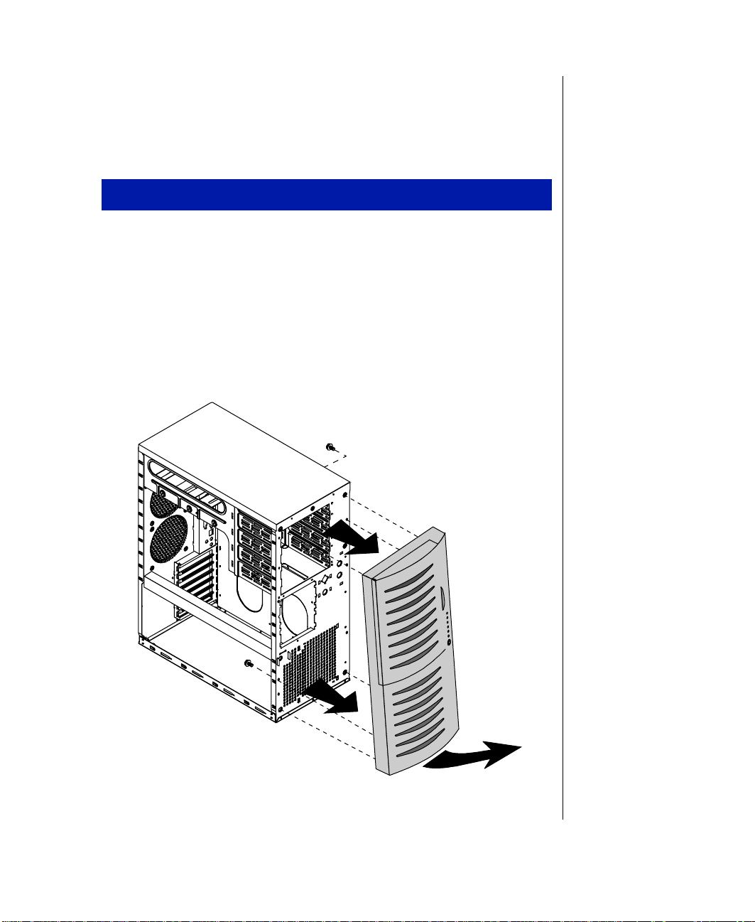
Removing the bezel
If you need to instal l or replace a 5.25-inch de vice or t he 3.5-inch diskett e
drive, y ou need to remo v e the front bezel.
To remove the front bezel
Foll ow the ESD precautions descri bed in “Static elect ricity
1.
precautions” on page 2.
T urn off the system and disconne ct the po w er cord.
2.
Remove both side panels as descr ibed in “Remo ving the side panel”
3.
on page 3.
From the inside of the cha ssis, remo ve the tw o scre ws securing the
4.
bezel to the chassis. See F igure 2.
Figur e 2: Remo ving the Beze l
System Access 5
Page 18

Holding onto the bottom handle, firmly pull the bezel aw a y from the
5.
chassis.
Set the bezel aside.
6.
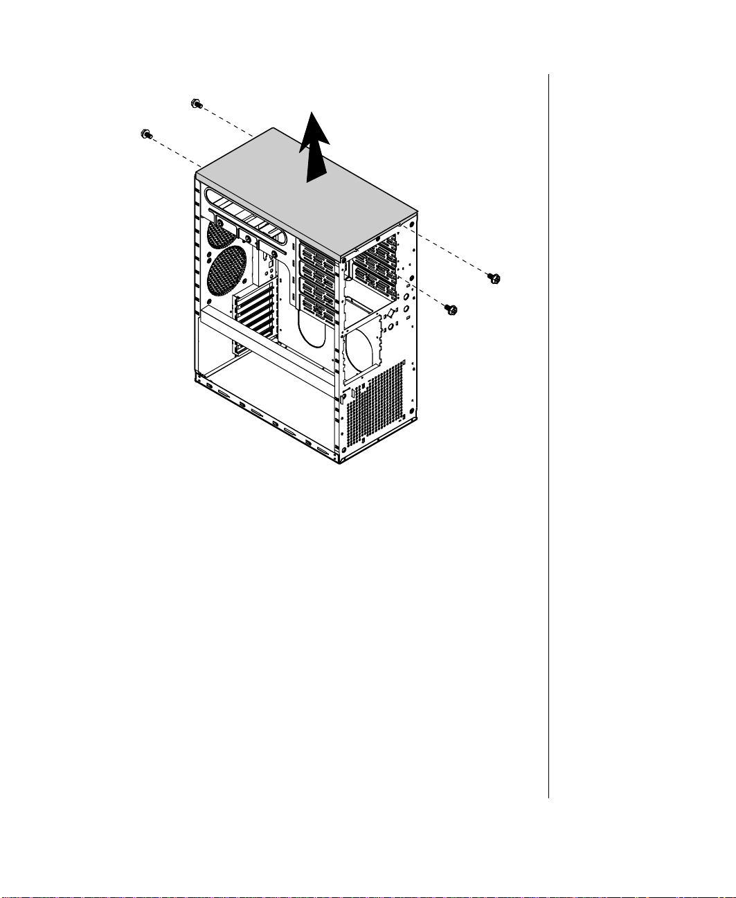
Removing the top cov er
It may be easier to access the cab les to the 3.5 -inch diskette dr iv e or an y
5.25-inch devices b y remo ving the top c o ver of the chas sis.
To remove the top cover
Foll ow the ESD precautions descri bed in “Static elect ricity
1.
precautions” on page 2.
T urn off the system and disconnec t the po w er cord.
2.
Remove side panel as described in “Removing the side panel” on
3.
page 3.
Remove the front bezel as describe d in “Remo ving the bezel” o n
4.
page 5.
Remove the four scre ws that secure the t op panel to the chassis. Tw o
5.
are located at the rear of t he system and tw o are located at the front of
the system. See Figure3.
6 Maintaining and Troubleshooting the Gateway ALR 7200 Server
Page 19
Figur e 3: Remo ving the Top Cove r
Pull the top co ver straight up.
6.
Set the co ver aside.
7.
System Access 7
Page 20
Closing the system
Before closing the system, ver ify that all connect ors and boards are
properly instal led and firmly seated.
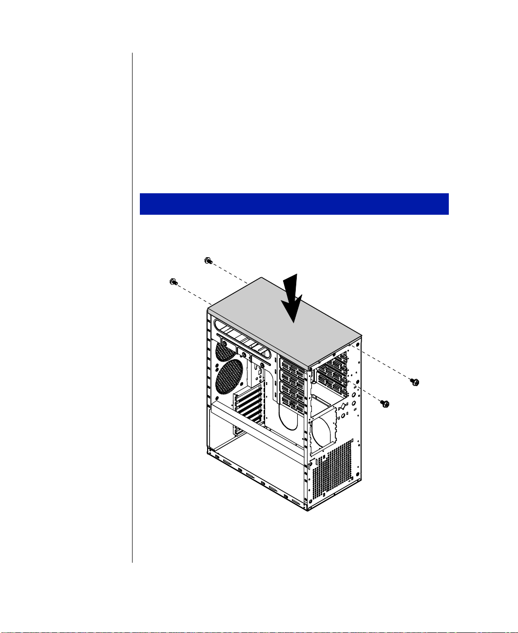
Replacing the top cover
If you ha ve remo v ed the top cover to access components at the top of the
system, replace the top co ve r before replacing oth er co veri ng pieces.
To replace the top cover
1.
Align the top co ver with the ledges on the chas sis. See Figure4.
Figur e 4: Repl acing the Top Cover
8 Maintaining and Troubleshooting the Gateway ALR 7200 Server
Page 21

Place the co ver strai ght do wn on the top of the cha ssis.
2.
Secure the co ver with the f our scre ws you remo v ed earlier.
3.
Replacing the bezel
After installing a 5.25-inch de vice or re placing the 3.5-inc h diskette dri ve,
replace the front bezel before y ou replace t he side panel.
To replace the front bezel
Position t he bezel to the front of the chassis so that t he bezel pe gs are
1.
aligned with the mount holes on th e front of the chassis . See Figure5.
Figur e 5: Replac ing the F r ont Bezel
System Access 9
Page 22
Insert the bezel pegs into the correct holes at the t op of the chassis.
2.
Swing the bottom of the bezel forw ard and press the pe gs into the
3.
correct holes, securing the bezel to the chassi s.
Secure the bezel with the tw o scr ews y ou remo ved w hen remo vi ng the
4.
bezel.
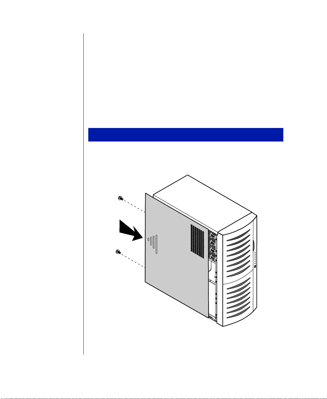
Replacing the side panel
The final step in closing the system is to replace the side panel.
To replace the side panel
Align the side panel with the led ges on the chassis.
1.
Slide the panel to ward t he front of the c hassis (see F igure 6).
2.
Figur e 6: Reinst alling the Side Panel
10 Maintaining and Troubleshooting the Gateway ALR 7200 Server
Page 23

Secure the panel with the scre ws y ou remo ved w hen opening the
3.
system.
If needed , repeat for t he other side panel.
4.
System Access 11
Page 24

12 Maintaining and Troubleshooting the Gateway ALR 7200 Server
Page 25

Components
System board components .................................... 14
Quick hot-swap RAID cage.................................. 24
SCSI backplane components ................................25
2
Page 26

System board components
The system board functions as the main int erface betw een the processor ,
memory , and peripherals. See the table below for the key to Figure 7.
Figur e 7: System Boar d
14 Maintaining and Troubleshooting the Gateway ALR 7200 Server
Page 27

Chassis fan connector
A
Po w er connector s
B
Soft pow er con nector
C
Chassis fan connector
D
Secondary IDE connector
E
Primary IDE connector
F
Floppy connector
G
Reset connector
H
Front panel cab le connector
I
External hard drive co nnector
J
Hard drive ac tivit y LED connector
K
Server management connector
L
User NMI connector
M
EDC reset connector
N
Chassis fan connector
O
Cov er intrusion swit ch connector
P
Speaker connector
Q
External boot ROM connector
R
External I2C connector
S
SCSI B connector
T
SCSI A connector
U
Clear CMOS jumper
V
Battery
W
ISA slot 1 (shared with secondary PCI slot 4)
X
Secondary PCI slot 4 (shared with ISA slot 1)
Y
Secondary PCI slot 3/RAID port
Z
Secondary PCI slot 2
AA
Secondary PCI slot 1
AB
Primary PCI slot 3
AC
Primary PCI slot 2
AD
Primary PCI slot 1
AE
Ethernet RJ45 connector
AF
Dual USB ports
AG
Video port
AH
Components 15
Page 28

Mouse/keyboard ports
AI
Serial port 2
AJ
Parallel port
AK
Serial port 1
AL
CPU connector 1
AM
CPU connector 2
AN
DIMM bank A
AO
DIMM bank B
AP
DIMM bank C
AQ
DIMM bank D
AR
CPU fan 1 connector
AS
Embedded VRM for CPU 1
AT
Socket for optional VRM for CPU 2
AU
CPU fan 2 connector
AV
CPU speed setting jumpers
AW
RAID cage connector
AX
LED display s witch con nector
AY
SHM mode jumper
AZ
Chassis fans
There are sev eral chassis fan connector s on the system board. These
connectors pro vide po w er for cooli ng fans that ma y be positioned i n sev eral
parts of the chassis to pro vide cooling f or critical compone nts.
P ower connectors
There are sev eral po w er connectors tha t pro vide po w er for t he system
board. Some of these connectors provide power for specialize d functions.
Primary power connectors
The primary pow er connectors provide the majority of the po w er to the
system board. These connectors are designed to a ccommodate the po w er
supply installe d in the system.
16 Maintaining and Troubleshooting the Gateway ALR 7200 Server
Page 29

Soft power connector
The soft pow er connector pro vides for the connection of a s witch that
pow ers up or po w er s do wn the server from a stand by state. Thi s feature is
not implemented on this system.
Drive controllers and connectors
There are sev eral controllers and connectors for the cont rol of the v arious
drives t hat are or can be instal led in the system.
Hard drive controller and connectors
This is an integrated dual-channel Ultra-DMA PCI/IDE inter face with tw o
IDE connectors capable of contr olling up to four IDE de vices and
supporting PIO Modes 0-4. Ultra-DMA pro vides faster access to IDE
devices that are Ultra-DMA compliant w hile maintaining support for IDE
devices that do not support the Ultra-DMA specification.
Floppy controller and connector
The floppy dri ve controll er and connector on the syst em board can support
up to two flo ppy dri ves of 1.44-MB and 2.88-MB formats.
SCSI controller and connectors
This integrated dual channel Adaptec® AIC™-7890 SCSI controller is a
high-performance, PnP compliant, single-chip PCI local bus-to-Ultra 2
SCSI master host adapter . Its adv anced SCSI I/O cell t echnolog y ensures
data integrity for higher I/ O bandwidth requirements wit h data rates of
40-MB/sec in Ultra mode and 80-MB/sec in Ultra2 mode.
Additional features:
Dual LVD 16-bit (68-pin) PCI-to-W ide Ultr a2 SCSI connectors
•
Full 32-bit PCI bus master implementation maximizing dat a
•
transfer on PCI local bus at 133-MB/sec dat a bursts
Components 17
Page 30

SCAM (SCSI Configured Automatically) Level 1 for W i ndows
•
®
enabling automatic configuration of new de vices with out
95
having to reboot the system.
Wide SCSI configuration supporting up to 15 connected SCSI
•
peripherals per channel, for a t otal of up to 30 de vices. Up to se ven
8-bit devices can be installed on each channe l.
Multithreading support for up to 255 simultaneous I/O tasks
•
Advanced SCSI I/O cell ensur ing data integrity b y automatic ally
•
and continuously adjus ting sle w rate to compensate f or SCSI bus
loading
Driver support for al l major operating systems.
•
F ront panel connectors
There are sev eral connectors that pro vide connectio n of the front panel
features to the system board. Some of these conne ctors are redundant,
allowing t he front panel feature s to vary according to t he system
requirements and the chassis configuration. Therefore some of these
connectors are not used in the syst em as shipped.
Reset connector
The reset connector pro vides the c onnection of the reset button from the
front co ver . This connector is not use d in this system.
Front panel connector
The front panel connector pro vides the signals for the f ront co ver indicator
LEDs and the front co ver buttons. This connec tor is not used in this syst em.
External HDD connector
The external hard driv e connector all ows y ou to connec t a cable fr om an
external hard driv e to the system board to allo w hard dri ve act ivity and
system monitoring to reco gnize the exte rnal drive.
18 Maintaining and Troubleshooting the Gateway ALR 7200 Server
Page 31

HDD LED connector
This connector allo ws you to connect all of the hard d ri ves to the hard dr iv e
activity connect or on the front co v er . This conne ctor is not used in thi s
system.
EDC reset connector
The EDC reset connector pro vides the connec tion for the k eyboard lock
button/ECC reset button from the front co v er . This connect or is not used in
this system.
Speaker connector
Connects the internal speaker to the s ystem board.
External boot ROM connector
Provides connection for e xpansion cards that conta in a separate boot R OM
and require separate access t o the system board.
LED display s witch connector
Connects the LEDs and switc hes on the front co v er to the system bo ard.
Server management connectors
The server management connectors pro vi de hardware an d component
monitoring to assist y ou in maintaining the server .
Server management connector
The server management connector allo ws you to connect a server
management device to the system boar d to monitor system acti vities.
Components 19
Page 32

Cover intrusion switch connector
Connects a co ver intrusion s witch to the system board so that the system
can monitor unauthorized access to t he chassis. This feature s is not
implemented in this system.
I2C connector
This connector is part of the system monitoring. It carries the sig nals of the
2
I
C bus which include identif ying information and status for major system
components.
RAID cage connector
The RAID cage connector connects the SCSI backplane to the system
board to allo w status and monitoring of backpla ne and SCSI driv e.
System jumpers
These jumpers allo w you to set c ertain characteristics of the system. Some
jumpers are reserved and are not descr ibed in this section. Do not change
any jumper unless it i s necessary to configure the system. In some cases,
changing the settings of reserved j umpers can cause damage to t he system
board.
Clear CMOS jumper
This jumper allo ws you to clea r the CMOS memory . You should only do
this if you cannot access t he normal methods of modifying the CMOS and
modifications to the CMOS are necessary. Cl earing CMOS memory
returns all BIOS Setup settings to the default v alues.
20 Maintaining and Troubleshooting the Gateway ALR 7200 Server
Page 33

CPU speed setting jumper
This jumper allo ws you to set the spe ed of the processor. Both processors,
in dual processor configurations, must have the same speed rating. If
processors of dif ferent speeds are used i n the same system, the processor s
must run at the speed of the slo w er processor.
SHM mode j umper
This jumper identifies the physical en vironment for t he InforManager
server management software. The jumper shu nt should be on the jumper
pins for this system.
Battery
Provides the po w er to maintain t he CMOS memory when the sy stem is
turned off or unplugged.
Expansion slots
The system features eight expansi on slots: five PCI slots, one ISA slot, one
PCI/RAID port, and one shared PCI/ISA slot.
The PCI bus processes peripheral trans actions at a system clock speed o f up
to 33 MHz.
Components 21
Page 34

I/O connectors
t
The I/O connectors are located on the back cover of the system. Figure 8
shows the connec tors and the tab le belo w pro vi des a key t o the figure.
Punchout section for
Parallel port Mouse port
optional external SCSI port
Serial port 1
Serial port 2
Keyboard
port
Dual USB
ports
Video port
Figur e 8: I /O Connectors
The following I/O connectors are incl uded with the system:
Two univ ersal serial bus (USB) ports. USB ports provide
•
connection for a growing l ist of peripheral c omponents including
mouse, keyboard , joystick, monitor, tape and flopp y dri ves. Up to
127 devices can be dais y-chained from each port. The USB port
also pro vides hot-sw ap capabi lity and dynamic resource allocation
for all peripherals atta ched to it with data tra nsfer rates of up to
12Mbps. USB drivers are pro vided as a part of most major
operating systems and should require no special procedures fo r
implementation or use.
Two 9-pin 16550-compat ible seri al ports
•
One bidirectional ECP/EPP parallel port
•
One video port
•
One PS/2-style mouse port
•
RJ45 Etherne
port
One PS/2-style keyboard port
•
22 Maintaining and Troubleshooting the Gateway ALR 7200 Server
Page 35

One RJ-45 Ethernet connector with two LED indicators. The green
•
LED indicates a communication link has been estab lished with the
network and the yello w ind icator sho ws that t he communication is
occurring at 100 Mbps.
Processor subsystem
The system board supports as many as tw o process ors (CPUs). The board
provides sev eral addition al connectors for supporting components, a s
described in the follo wing paragraphs.
CPUs and CPU slots
Depending on the model, the system is equipped with one Intel P entium® II
processor with 512-KB ECC L2 cache, integrated into a Singl e Edge
Contact (SEC) cartridge.
The system’s SMP design supports up to tw o processors and i s Intel MP
Specification v1.1 and 1.4 compliant.
CPU fan connectors
The CPU fan connectors provide pow e r for the fans mounted on the
processor heatsinks. These fans cool the processors and pre vent
ov erheating. Note tha t not all processor he atsink ha ve or need fans. If the
processor heatsink includes a fan, connec t it to the correct fan connector .
V oltage regulator modules
Each CPU must have a dedicated vol tage regulato r module (VRM) which
adjusts the voltage suppli ed to the CPU. The VRM for the first CPU (CPU
1) is embedded on the system board.
Memory
The system comes standard with 64-MB of Error Checking and Correcting
(ECC) RAM. System RAM is expandable up to 1-GB using ECC 60-ns
72-bit synchronous DRAM (SDRAM) DIMMs (4 DIMM sockets).
Components 23
Page 36

Important!
The quick hot-swap RAID
Cage may or may not be
included as a standard part of
the server configuration.
Quick hot-swap RAID cage
The quick hot-sw ap cage allo ws y ou to configure a reliable RAID
subsystem. The quick hot-s wap cage consi sts of a dri ve cag e and all of the
necessary hardware to install it in the system (Figur e 9). Each cage supports
three one-inch high 3.5-inch SCA SCSI dri ves. F or opti mum operation, use
only appro ved RAID-ready driv es in the RAID Cage. The RAID Cage
occupies two s tandard half-height 5.25 -inch dri ve ba ys.
Drives are mounted on a rail system w hich pro vi des quick and easy
installation and hot-sw apping. A full y functional RAID subsystem is
controlled by a RAID cachi ng controller .
Hot-swapping is a useful features that allo ws y ou to replace a failed ha rd
disk drive without interrupting system operation. In the e vent of a
hot-swappa ble dri ve failure, w hich is part of a RAID 5, the system
continues normal operations. You can replace the failed dri ve and r ebuild its
contents on an equiv alent replace ment driv e automaticall y, without shutting
down the syste m.
Figur e 9: RAID Ca ge
24 Maintaining and Troubleshooting the Gateway ALR 7200 Server
Page 37

SCSI backplane components
The SCSI backplane connects the SCA-2 LVD SCSI drives to the SCSI
RAID controller or the SCSI controllers on t he system board. The
backplane pro vides automatic SCSI address setting and allo ws
hot-swappi ng of SCSI driv es. Figu re 10 sho ws the back of the backpla ne
where the dri ves conn ect.
Figur e 10: The Bac k of the SCSI Bac kplane
T o configure the quick hot-sw ap backplane, see t he Quic k Hot-swap
Installation Guide that w as shipped with the system.
Components 25
Page 38

26 Maintaining and Troubleshooting the Gateway ALR 7200 Server
Page 39

Chapter 1:
Installing Components
Replacing the processor......................................... 28
Installing a second processor.................................31
Setting the jumpers................................................ 33
Installing memory and hardware.......................... 35
Installing and using drivers and other software.... 59
3
Page 40

Replacing the processor
The system is compatible wit h Intel P entium® II processors.
You can either upgrade the existing Pentium II processor or install a second
processor of the same speed as the first processor .
When replacing a processor , order a Pent ium II processor upgrade kit. The
kit includes the P entium II processor , a heat sink, and a disposab le
electrostatic dischar ge (static el ectricity) wrist strap.
It is critical that a he at sink be installed o n each P entium II processor. The
Pentium II pr ocessor o v erheats and fails if it is not cooled suf ficiently. The
heat sink pro vided with the P ent ium II processor on the syst em pro vides all
necessary cooling for the processor .
For t he latest details on the a vai lability of the upgrade kits, cont act one of
the sources listed in the Assi stance Resour ces document.
To replace the processor
1.
T urn off the system and disconnec t the po w er cord.
2.
Open the case (“Opening the system” on page 3), observing the static
electricity precautions in “Sta tic electricit y precautions” on page 2.
3.
Wearing an anti-static wristband grounded to the system chass is,
remov e the lock bar f rom the processor slot b y remo ving the two
screws that secure it (see Fi gure 11).
28 Maintaining and Troubleshooting the Gateway ALR 7200 Server
Page 41

Figur e 11: Remo ving the Pentium II Pr ocessor
Lift the cartridge up and a w a y from the system board.
4.
Place the processor cartridge t hat you removed in a safe place.
5.
Remove the replacement proc essor cartridge from it s protecti ve
6.
wrapping and place it in the cartrid ge supports for the slot 1 connecto r .
Slide the cartridge all of the wa y do wn until it is firmly seated.
7.
Figur e 12: Ins talling the Pentium II Processor
Installing Components 29
Page 42

If the processor cartridge does not already ha ve the hea tsink attached
8.
to it, attach the heatsink acc ording to the instructions that came with
the processor upgrade kit.
Replace the lock bar on the processor support and secure it with the
9.
two scre ws that y ou remo v ed earlier .
Set the jumpers for the ne w processor configuration (see the table o n
10.
page 33).
Close the case, as described in “Closing the syst em” on page 8.
11.
Reconnect the po wer cor d and turn on the system.
12.
30 Maintaining and Troubleshooting the Gateway ALR 7200 Server
Page 43

Installing a second pr ocessor
The system is compatible wit h Intel P entium® II processors.
You can either upgrade the existing Pentium II processor or install a second
processor of the same speed as the or iginal processor.
When adding a processor , order a P entium II processor upgrade kit. The kit
includes the P entium II processor , a heat sink, and a disposab le electros tatic
discharge (static electricity) wri st strap.
It is critical that a he at sink be installed on each P entium II processor. The
Pentium II processor o v erheats and fails if it is not cooled suf ficiently. The
heat sink pro vided with the P ent ium II processor on the syst em pro vides all
necessary cooling for the processor .
For t he latest details on the a vai lability of the upgrade kits, cont act one of
the sources listed in the Assi stance Resour ces document.
To install a second processor
1.
T urn off the system and disconne ct the po w er cord.
2.
Open the case (“Opening the system” on page 3), observing the static
electricity precautions in “Sta tic electricit y precautions” on page2.
3.
Remov e the Terminator Card from the system board.
Figur e 13: Remo ving the Terminator Car d
Installing Components 31
Page 44

Align the new P entium II SEC cartridge i nto the CPU 2 connector and
4.
press it firmly into place.
Important!
After you install a new
processor, you ma y see the
following message at start
up: Update table not f ound
for CPU
xx
you see this message, run
, Stepping
the MULOADER utility,
which is on the diskette
supplied with your
processor.
xxx
. If
Figur e 14: Ins talling the Pentium II Processor
Place the lock bar on top of the supports and secur e it by i nserting and
5.
tightening the tw o scre ws.
Set the jumpers for the ne w processor configuration (see the table o n
6.
page 33).
Close the case, as described in “Closing the syst em” on page 8
7.
Reconnect the po wer cor d and turn on the system.
8.
32 Maintaining and Troubleshooting the Gateway ALR 7200 Server
Page 45

Setting the jump ers
The system board jumpers let you change sev eral system functions.
Jumpers are set to the default positi ons at the factory. You ma y need to
change the jumper settings to perf orm the follo wing functions:
Set processor/bus speed settings
•
Clear CMOS memory
•
Processor speed jumper
The system board supports a range of processor speeds , which are set by
changing jumpers. If you upgrade your pr ocessor , you ma y need t o change
jumper settings. The Processor Speed jumper (JP22) configuration block
lets you set the proc essor speed.
The system automaticall y detects the bus spee d supported by the proces sor
and uses the jumper settings in conj unction with the detecte d bus speed to
set the processor speed. If two processors are present and they support
different speeds, the s ystem will operate at the slower speed. Mo ve the
jumper shunts on jumper b lock JP22 to connect th e jumper pins according
to the table belo w. Processor speeds are gi v en in relation to bus s peeds of
66MHz/100MHz.
Caution!
Do not run your processor
at a speed higher than it is
rated or you will cause
irreparable damage to your
system.
Installing Components 33
Page 46

Clear CMOS jumper
The Clear CMOS jumper (JP15) lets y ou clear all current v alues in
complimentary metal-oxide semiconductor (CMOS) memory. CMOS
memory stores all of the BIOS Setup information and settings. Clearing the
CMOS memory restores all setup values t o the original s ystem defaults.
A jumper shunt connecting pins 1 and 2 is for normal operations. A jumpe r
shunt connecting pins 2 and 3 is for c learing the CMOS memory .
To clear CMOS memory
You must restart the server and press
1.
Write down the current BIOS configuration settings for later
2.
F
to enter the BIOS Setup utility.
2
reference.
T urn off the system and disconnec t the po w er cord.
3.
Open the case (“Opening the system” on page 3), observing the static
4.
electricity precautions in “Sta tic electricit y precautions” on page 2.
Move t he jumper shunt on the Clear CMOS (JP15) j umper to connect
5.
pins 2 and 3.
Reconnect the po wer cor d and turn on the system.
6.
T urn off the system again a nd disconnect the po w er cord.
7.
Move t he jumper shunt on the Clear CMOS (JP15) j umper back to its
8.
normal position connecting pins 1 and 2.
Close the case, as described in “Closing the syst em” on page 8.
9.
Reconnect the po wer cor d and turn on the system.
10.
Clearing the CMOS memory clears all passw ords and all configuration
settings. You will need to reset any necessary v alues in BIOS Setup after
you clear CMOS memory .
34 Maintaining and Troubleshooting the Gateway ALR 7200 Server
Page 47

Installing memory and har dware
Installing memory
The system board supports up to 1 GB of RAM in ECC SDRAM DIMMs.
The system board is configured with 4 DIMM banks. You can fill Bank 0,
Bank 1, Bank 2, or Bank 3 or a combination of banks with DIMMs. No
jumper settings are required f or the memory size or type because thi s
information is automaticall y detected b y the BIOS.
Refer to the DIMM configuration chart later in this section for v alid
memory configurations. You may select any c ombination that pro vides t he
total RAM required by y our system and applica tions.
To install DIMMs
1.
T urn off the system and disconne ct the po w er cord.
2.
Open the case (“Opening the system” on page 3), observing the static
electricity precautions in “Sta tic electricit y precautions” on page2.
3.
Pull open the socket clamps on each side of the DIMM sock et.
Figur e 15: Opening t he DIMM Socket Clamps
4.
Insert the DIMM into the socket and align the tw o notches in the
DIMM with the two not ches in the DIMM sock et.
Installing Components 35
Page 48

Figur e 16: I nserting the DIMM
Gently press the DIMM int o the socket unti l it is firmly seated.
5.
(Inserting the DIMM automaticall y locks the sock et clamps on each
end of the DIMM.)
Close the case, as described in “Closing the syst em” on page 8.
6.
Reconnect the po wer cor d and turn on the system.
7.
Caution!
Never try to remove a
DIMM without releasing the
clamps. You may break the
socket, causing serious
damage.
Gently push out the pla stic socket cla mps on each end of the DIMM .
1.
The DIMM should pop up slightly fr om the socket.
To remove DIMMs
Figur e 17: Relea sing the DIMM Socket Clamps
36 Maintaining and Troubleshooting the Gateway ALR 7200 Server
Page 49

Carefully lift the DIMM out of the soc ket.
2.
Figur e 18: Remo ving the DIMM
Store the DIMM in a static-free container.
3.
DIMM configurations
You can use 8-MB, 16-MB, 32-MB, 64-MB , 128-MB , and 256-MB
DIMMs in any combination, bank, or order to expand the SDRAM up to
1 GB. Refer to the follo win g table to configure your RAM.
T otal
(MB)
RAM Type Size
32 2x72 16 2x72 16 -- -- -- -32 4x72 32 -- -- -- -- -- -48 2x72 16 2x72 16 2x72 16 -- -48 2x72 16 4x72 32 -- -- -- -64 2x72 16 2x72 16 2x72 16 2x72 16
64 4x72 32 4x72 32 -- -- -- -64 4x72 32 2x72 16 2x72 16 -- -64 8x72 64 -- -- -- -- -- --
DIMM
Socket 1
(MB)
DIMM
Socket 2
Type Size
(MB)
DIMM
Socket 3
Type Size
(MB)
DIMM
Socket 4
Type Size
(MB)
Installing Components 37
Page 50

96 8x72 64 4x72 32 -- -- -- -96 8x72 64 2x72 16 2x72 16 -- -96 4x72 32 4x72 32 2x72 16 2x72 16
12816x72128-----------128 8x72 64 8x7 2 64 -- -- -- -128 8x72 64 4x7 2 32 4x72 32 -- -128 8x72 64 4x7 2 32 2x72 16 2x 72 16
192 16x72 128 8x72 64 -- -- -- -192 16x72 128 4x72 32 4x72 32 -- -192 16x72 128 4x72 32 2x72 16 2x72 16
192 8x72 64 8x7 2 64 8x72 64 -- -192 8x72 64 8x7 2 64 4x72 32 4x 72 32
25632x72256-----------256 16x72 128 16x72 128 -- -- -- -256 16x72 128 8x72 64 8x72 64 -- -256 8x72 64 8x7 2 64 8x72 64 8x 72 64
384 32x72 256 16x72 128 -- -- -- -384 16x72 128 16x72 128 16x72 128 -- -384 16x72 128 16x72 128 8x72 64 8x72 64
512 32x72 256 32x72 256 -- -- -- -512 32x72 256 16x72 128 16x72 128 -- -512 32x72 256 16x72 128 8x72 64 8x72 64
512 16x72 128 16x72 128 16x72 128 16x72 128
1-GB 32x72 256 32x72 256 32x72 256 32x72 256
Adding and replacing drives
The case must be opened to add or replace dri ves ( such as hard disk dri ves
and CD-ROM dri ves) i n the system. Refer to “Opening the syst em” on
page 3, for instructions on opening the case and “Closing the sys tem” on
page 8 for information on closing the case.
38 Maintaining and Troubleshooting the Gateway ALR 7200 Server
Page 51

Replacing a 3.5-inch drive in the front drive bay
The 3.5-inch driv es are secured to a metal mountin g bracket, wh ich enab les
easy installation and remo v al from the system chassis. This brack et
supports a 3.5-inch diskette dri ve w hich w as installed at t he factory. There
is space in the bracket f or a second front-acces sible dri v e and up to tw o
internally accessib le one inch tall 3.5-inch dri ves.
To replace the 3.5-inch diskette drive
T urn off the system and disconne ct the po w er cord.
1.
Open the case (“Opening the system” on page 3), observing the static
2.
electricity precautions in “Sta tic electricit y precautions” on page2.
Locate the 3.5-inch dri ve bracke t.
3.
Disconnect the po w er and data cab les from the back of the dri ve that
4.
you want to r eplace, noting their l ocation and orientati on. (You will
reconnect these cabl es after you install the ne w dri ve.)
Installing Components 39
Page 52

Remove the screws s ecuring the dri ve br acket to the syst em chassis,
5.
and remov e the dri ve brack et from the chassis. Doing so a lso remo ves
the 3.5-inch metal filler panel from the front of the dri ve brack et (see
Figure 19).
Figur e 19: Remo ving the 3.5-inc h Drive Br ac ket
Remove the screws securing the 3.5-inch dri ve to the bracket , and then
6.
remov e the 3.5-inch dri ve (see Figure20).
40 Maintaining and Troubleshooting the Gateway ALR 7200 Server
Page 53

Figur e 20: Remo ving the 3.5-i nch Drive
Place the new 3.5-inch dri ve in t he mounting bracket (s ee Figure21).
7.
Figur e 21: Instal ling the New 3.5-inc h Drive
Secure the driv e to the mounting br acket using the sc rews y ou
8.
removed in Step 6.
Installing Components 41
Page 54

Place the driv e bracket in t he chassis (see F igure 22). If you are
9.
installing a second front-ac cessible dr iv e, do not reinstall t he 3.5-inch
metal filler panel when you reinstall the driv e ba y in the chassis.
Figur e 22: Replaci ng the Drive Br ac ket
Secure the driv e bracket to t he chassis with th e screws y ou remo v ed in
10.
step 5.
Connect the pow er and dat a cables to the 3.5-inch driv e, making sure
11.
the cables match their original position. ( See driv e documentation fo r
proper drive jumper settings and cab le orientation.)
Close the case, as described in “Closing the syst em” on page 8.
12.
Reconnect the po wer cor d and turn on the system.
13.
42 Maintaining and Troubleshooting the Gateway ALR 7200 Server
Page 55

Installing a drive in the 5.25-inch drive bay
The 5.25-inch driv e ba y supports a CD-R OM driv e, diskette dri ve, or other
5.25-inch device.
To install a drive in the 5.25-inch drive bay
T urn off the system and disconne ct the po w er cord.
1.
Open the case (“Opening the system” on page 3), observing the static
2.
electricity precautions in “Sta tic electricit y precautions” on page2.
Locate the 5.25-inch driv e ba y.
3.
If no driv e is installed in t he driv e ba y, remov e the metal dri ve ba y
4.
cov er from the front of the 5.25-i nch driv e ba y. Also, remov e the
plastic driv e ba y co ver on the front bezel.
If you are replacin g an existing dri v e, disconnect the po w er a nd data
5.
cables from the dri ve, not ing their location and o rientation. (You will
reconnect these cabl es after you install the ne w dri ve.)
Squeeze the tabs at the ends of the guide rails in to w ard the cent er of
6.
the drive and pull the dri ve out of t he chassis (see F igure 23).
Installing Components 43
Page 56

Guide rail
Tab
Figur e 23: Remo ving a 5.25-inc h Drive
Remove the screws t hat secure the dr iv e rails to the dri ve and remo ve
7.
the rails.
Mount the guide rails to the ne w driv e using the scre ws you re mo ved
8.
from the old drive.
Align the guide rails with the ra il guides in the dri ve bay and slide the
9.
drive all of the wa y into the ba y. The tabs on the rails will click int o
place when the dri ve is full y inserted (see Figure24).
44 Maintaining and Troubleshooting the Gateway ALR 7200 Server
Page 57

Figur e 24: I nstalling a Drive i n the 5.25-Inch Driv e Bay
Connect the pow er and dat a cabl es to the back of the dri ve . (See dri ve
10.
documentation for proper dri ve jumper se ttings and cab le orientation.)
Close the case, as described in “Closing the syst em” on page 8.
11.
Reconnect the po wer cor d and turn on the system.
12.
Run the configuration software that came with the dri ve, if required.
13.
The system should automaticall y recognize the new dri v e. If it does
14.
not, you ma y need to set jumpers on the dr iv e or change settings i n the
BIOS Setup utility.
Installing Components 45
Page 58

Replacing the RAID cage in the 5.25-inch drive ba y
The Quick Hot-Swap Dri ve Cage consist s of a dri ve cage, a locking doo r ,
and all the necessary hardware t o install it in t he system. Each cage
supports three drives. Be gin cage installa tion from the bottom dri ve ba y.
Figur e 25: Hot-Sw ap Drive Cag e
To replace the RAID cage
Remove the side panel as descri bed in “Remo ving the side panel” on
1.
page 3.
Disconnect all cables connect ing the RAID Cage to other system
2.
components.
Remove the driv es:
3.
Pull the latching clips outw ard to release the driv e from the RAID
A.
Cage (see Figure 26).
46 Maintaining and Troubleshooting the Gateway ALR 7200 Server
Page 59

Figur e 26: Re moving the S CSI Drives
Pull the driv e out of the dri ve cage.
B.
Place the driv e in a safe place, pr eferabl y in an anti- static bag.
C.
Repeat steps a–c for all dri ves i n the dri ve cage.
D.
Remove the old RAID Cage by pre ssing the tabs on the sl ide rails
4.
tow ard the cente r of the cage and pulling t he cage out of the 5.2 5-inch
drive ba y (see F igure 27).
Installing Components 47
Page 60

Figur e 27: Remo ving the RAID Ca ge
Installing the new RAID cage
Slide the new dri ve cage into the dri ve brac ket as sho wn in F igure 28.
1.
Figur e 28: I nstalling the RAID Ca ge
48 Maintaining and Troubleshooting the Gateway ALR 7200 Server
Page 61

Connect all cables that conne ct the RAID Cage and its backplane t o
2.
other system components.
Reinstall the SCSI driv es in the ne w RAID cage by al igning the rails
3.
and sliding them all the w a y into the cag e (see Figure29).
Important!
Each drive has a Drive
Number label af fixe d t o the
front of the drive. The drive
number on t he la be l
corresponds to the device's
SCSI ID. Driv e s must be
installed in ascending order
starting from the bottom bay .
Figur e 29: Re placing the SCSI Drives
Secure the driv es by cl osing the latchi ng clips.
4.
Installing Components 49
Page 62

Replacing a hard disk in the rear drive bay
The hard disk is secured to a metal mounti ng bracket, w hich enab les the
drive to be easily i nstalled and remo v ed from the sys tem chassis. This
procedure refers to the inte rnal 3.5-inch driv e ba y, not to the 3.5-inch ba y at
the front of the chassis.
To replace a hard drive in the rear drive bay
T urn off the system and disconnec t the po w er cord.
1.
Open the case (“Opening the system” on page 3), observing the static
2.
electricity precautions in “Sta tic electricit y precautions” on page 2.
Locate the hard disk assembl y beneath t he po w er supply a t the rear of
3.
the chassis.
Disconnect the data and po w er cab les from the hard disk driv e, noting
4.
their location and orientat ion. (You will reconnect these cables w hen
you install the ne w hard dri ve.)
Remove the screws t hat attach the hard di sk mounting bracket to the
5.
chassis, and remo ve the bracket from the chas sis (see F igure 30).
Figur e 30: Remo ving the Har d Disk Br acket and Drive
50 Maintaining and Troubleshooting the Gateway ALR 7200 Server
Page 63

Remove the screws t hat attach the hard driv e to the mounting brac ket
6.
and remov e the hard dri ve (see Figure 30).
Secure the new hard dri ve to the mounting bracket using t he screws
7.
you remo ved in Step 6 ( see Figure31).
Figur e 31: Inst alling a Har d Drive in the Rear Drive Bay
Place the hard disk assemb ly into t he chassis and secure it to the
8.
chassis using the scre ws you remo v ed in Step 5 (see F igure 31).
Connect the data and po w er cabl es to the hard dri ve, making sure the
9.
cables match their or iginal position. (See t he driv e documentation for
proper drive jumper settings and cab le orientation.)
Close the case, as described in “Closing the syst em” on page 8.
10.
Reconnect the po wer cor d and turn on the system.
11.
The system should automaticall y recognize the new dri v e. If it does
12.
not, you ma y need to set jumpers on the dr iv e or change settings i n the
BIOS Setup utility.
Installing Components 51
Page 64

Installing the SCSI cable kit
If you wish to use a standalone SCSI de vice (suc h as a scanner) outside of
the system chassis, you can inst all a SCSI cab le kit. The kit (P/N 1504961)
enables you t o connect a cabl e from the inte grated onboard SCSI connector
on the system board to the rear panel of the chassis.
To install the SCSI cable kit
Po w er do wn the sy stem and remo ve t he po w er cord(s).
1.
Remove the parts from the SCSI Cable Kit and lay them out on a
2.
workbench.
Open the case (“Opening the system” on page 3), observing the static
3.
electricity precautions in “Sta tic electricit y precautions” on page 2.
Use a straight blade scr ewdri ver to remo v e the punchout section on the
4.
rear panel of the chassis (i nsert the blade of the s crewdri v er into the
slot in the punchout, then pry back and forth until loose).
SCSI cable
SCSI connector
on system board
Figur e 32: Instal ling the SCSI Cab le Kit
One end of the SCSI cable is at tached to a brack et containing tw o
5.
threaded holes. From the ins ide of the system, hold this end of the
cable up to the opening creat ed when the punchout w as remo v ed.
Using the two smal l screw s included in the kit , secure the SCSI cab le
6.
to the rear panel of the chassi s.
52 Maintaining and Troubleshooting the Gateway ALR 7200 Server
Punchout section
Page 65

Plug the other end of the SCSI cable into the appropriate SCSI
7.
connector on the system board.
Arrange the ribbon cable so that it does not interfere with t he chassis
8.
or CPU fans, or block airflo w through t he system.
Close the case, as described in “Closing the syst em” on page 8.
9.
Plug in the system po w er cord(s) and po w er up t he system.
10.
Adding an expansion card
The system board has seve n (7) expansion sl ot connectors. The system
board accepts tw o types of expan sion cards: ISA and PCI. Some of the PCI
expansion slots are desi gned to allo w the slot to be shared with a speci al
purpose expansion card such as a RAIDport card.
Some ISA expansion cards ha ve jumpers or switches t hat set interrupts and
I/O addresses. They come with instructions that e xplain ho w to set them t o
avo id hardw are conflicts. Follow the instructions careful ly.
Refer to Figure 7 on page 14 f or the correct installation loca tion.
To add an expansion card
Set any jumpers and s witches on the card , if required in the card
1.
instructions.
T urn off the system and disconne ct the po w er cord.
2.
Open the case (“Opening the system” on page 3), observing the static
3.
electricity precautions in “Sta tic electricit y precautions” on page2.
Locate an open slot of the correct type.
4.
Remov e and retain the sc rew securi ng the expansion port co v er to the
5.
rear co ver . Keep the port co v er for reinst allation in case y ou e ver need
to remov e the card (F igure 33).
Firmly insert the edge of the expa nsion card into the slot .
6.
Important!
For full length cards, make
certain that the end of the
card is aligned with the
correct slot in the card
guide. When the card is
fully inserted, the plastic
retaining clip will snap back
out to hold the end of the
card in position.
Installing Components 53
Page 66

Figur e 33: Inst alling an Expansion Car d
After seating the card firmly , secure i t to the chassis b y instal ling the
7.
screw you r emo ved in Step 5 through t he mounting bracket at the e nd
of the card.
If required , conne ct cables t o the card. (See card documentat ion for
8.
proper jumper settings and cab le orientation.)
Close the case, as described in “Closing the syst em” on page 8.
9.
Reconnect the po wer cor d and turn on the system.
10.
It may be necessa ry to reconfigure your system after installing some
expansion cards. You may also need to install s oftware t hat came with the
card. Check the card documentation for additi onal information.
54 Maintaining and Troubleshooting the Gateway ALR 7200 Server
Page 67

Removing an expansion card
Removing an e xpansion card ma y require y ou to run software to
reconfigure the system.
To remove an expansion card
T urn off the system and disconne ct all po w er cords and peri pheral
1.
devices.
Open the case (“Opening the system” on page 3), observing the static
2.
electricity precautions in “Sta tic electricit y precautions” on page2.
If necessary , disconn ect an y cables conne cted to the expans ion card.
3.
Remove the screw t hat secures the c ard and its bracket to the back
4.
panel of the server (see F igure 34).
Figur e 34: Remo ving the Expans ion Car d Scr ew
Installing Components 55
Page 68

For fu ll-length cards, pres s the retaining latch on the card guide i n,
5.
until it clicks into the retr acted position ( see Figure35).
Retaining
Release
button
latch
Figur e 35: Pr essing t he Retaining Latch
Gently but firmly pull the expansion card out of the chassis.
6.
Press the release button on the car d guide to return the retaining l atch
7.
to the extended position.
Place an expansion port co ver over the empty slot and secure it with
8.
the screw y ou remo ved earlie r .
Replace the co ver , rec onnect the peripherals and po w er cord , and turn
9.
on the system.
56 Maintaining and Troubleshooting the Gateway ALR 7200 Server
Page 69

Replacing the battery
The battery provides pow e r for the system real- time clock and CMOS
RAM, which holds the system configuration information.
To replace the battery
Restart the computer and start the BIOS Setup program b y pressing
1.
when you are prompte d to do so.
Write down the CMOS values from the Main Setup s creen so you can
2.
re-enter them after y ou replace the ba ttery. (For more information
about the setup program, see “About the BIOS setup utility” on
page 62.)
T urn off the system and disconne ct the po w er cord.
3.
Open the case (“Opening the system” on page 3), observing the static
4.
electricity precautions in “Sta tic electricit y precautions” on page2.
Locate the battery on the system board (see F igure 7 on page 14). The
5.
battery is circular and has the positi ve pole mark (+) on the top.
Gently pull the battery from its socket, and pre ss the new battery in the
6.
socket with the positi ve pole (+) up. Be sure y ou ha ve press ed the
battery down far enough for it to contact the base of t he socket.
Caution!
There is a danger of
explosion if the battery is
incorrectly replaced.
Replace the battery only
with the same or equivalent
type recommended by the
manufacturer . Dispose of
F
2
used batteries according to
the manufacturer’s
instructions.
Close the case, as described in “Closing the syst em” on page 8.
7.
Reconnect the po wer cor d and turn on the system.
8.
Enter the BIOS Setup program and v erify that the sys tem
9.
configuration is correct using the data you recorded in Step 2.
If the CMOS data is not correct, change the information in the setup
screens as necessary.
Installing Components 57
Page 70

Troubleshooting the battery installation
If you ha ve prob lems after insta lling the ne w battery, try each of the items
listed belo w, replacing the co ver and resta rting the computer after each try.
T urn off the system and ensure t hat all exte rior cable s are attached
•
to the correct connectors and secured.
Check to be sure that all po w er s witches are on. If t he system is
•
plugged into a po w er strip or sur ge protector , be sure it is turned on
also.
Enter the BIOS Setup program and compare the setti ngs on the
•
screen with your notes or the s ystem hardw are manuals. Correct
any discrepancies.
T urn off the system, remo ve the co ver , and v erify that all cab les
•
inside the case are attached secure ly. Also, make sure that the
colored cable ed ges are aligned correctl y and that the connector s
didn’ t miss any pins. Disconnect and reconnect the cab les, and then
replace the co ver care fully so as not to disturb any cab les.
T urn off the system, remo ve the co ver and, if you hav e the proper
•
test equipment, verify th at the new bat tery has pow er. (It is
possible, although highl y unlik el y, that your new batte ry is
defective.)
If these procedures fail to correct the prob lem, contact Technical Support.
When everything w orks proper ly, close the case as described in “Cl osing
the system” on page 8, reconnect the pow er cor d , and turn on the system.
58 Maintaining and Troubleshooting the Gateway ALR 7200 Server
Page 71

Installing and using driver s and other software
Some tips on installing and using dri ve rs or other softw are in criti cal
situations or under particular circumst ances are pro vided belo w.
Installing video drivers
Included with your syste m is a Cirrus Logic Windo ws NT 4.0 v1.40
diskette. When loading y our video dri vers, use the d riv ers pro vided on this
diskette instead of the ones on t he W indo ws NT CD-R OM. The dri vers on
the Windo ws NT CD-R OM ma y not w ork correctly with y our system.
Installing the NetWare 4.11 driver
When installing the second instance dri ver for the second SCSI controller ,
the server will generate interrupts that hang the server . T o resolve this issue,
replace the MPS14.PSM file that is installed during the NetW are 4.11
installation with an updated v ersion of the file. The updated file can be
obtained from the Netwar e Service Pack 5 utility patch provided by No vell.
Use one of the follo wing tw o methods to update the MPS14.PSM file:
After NetW are is installed and befo re loading the second on- board
•
SCSI driver , the updated MPS14.PSM file can be copied to the
C:\NWSER VER subdir ectory to overwri te the older version placed
during installation. Restart the server and the s econd on-board
SCSI driver will l oad successfull y.
During the NetWare installation, select SMP support, a message to
•
install an unlisted PSM file will display. Path to the loca tion of the
updated PSM file and load it. Once loaded, the updated PSM file
will automaticall y be copied to the NetWare installation direct ory .
Once the file has been copied you can successfully load the second
on-board SCSI driver.
Installing Components 59
Page 72

Updating Seagate Backup Exec files
Once Seagate Backup Exec ha s been installed and the pro gram started , the
CLIB and DSAPI modules report errors while loading. Backup Exec wil l
continue to run after the errors appear. Backup Ex ec recommends that these
files be updated to a later version. The updated files can be obtained from
Nov ell’s website at the follo wing location:
http://support.nov ell.com/cgi-bin/sea rch/do wnload?/pug/updates/nw/inw41
1/libuph.exe &sr
The update files are CLIB.NLM and DSAPI.NLM.
60 Maintaining and Troubleshooting the Gateway ALR 7200 Server
Page 73

Chapter 2:
BIOS Setup
About the BIOS setup utility.................................62
Using the BIOS setup utility................................. 63
Updating the BIOS................................................ 82
4
Page 74

About the BIOS setup ut ility
The computer BIOS has a built-in program that let s you set man y basic
system characteristics. These se ttings are stored and sav ed e ven w hen the
pow er is of f. This chapt er contains information about this setup utility and
is intended to serve as a guide so tha t you can mak e changes to y our system
BIOS when necessary .
Many of the screen examples that y ou see in this cha pter are identical to
what you see on y our monitor; ho w e ver , y ou ma y ha ve a system with a
new er BIOS versi on than the one described i n this manual. In that case,
some of the examples ma y dif fer somew hat from wha t you see, but the
screens are similar enough that y ou should ha v e no troubl e getting the
information that you need.
62 Maintaining and Troubleshooting the Gateway ALR 7200 Server
Page 75

Using the BIOS setup utility
The computer BIOS has a built-in setup util ity that lets y ou configure
several b asic system charact eristics. The setti ngs are stored in
battery-backed CMOS memory and are retained e ven w hen the po w er is
off.
T o enter the s etup utility, restart the system and then press
F
2
when
prompted on screen during the startup process. Upon entering setu p, the
Main Setup screen opens.
Figur e 36: BIOS Menu Navig ation K eystrokes
The low er sec tion of all screens pr o vides information about k eystrokes
necessary to access help, navig ate through the menus, and perf orm other
functions.
Help—Press
•
F
to get information about the selected item. This
1
item is only usab le in a submenu.
Exit—Press
•
Select Item—Press the up arro w or do wn arrow ke ys to mo v e to
•
E
to back out of any field.
SC
the next or previ ous menu item.
Select Menu—Use the left arro w and right arrow k eys to mo v e
•
between the main menus ( Main, Advanced, Security , Boot and
Exit).
Change Values—Use the plus (+) ke y or the minus (-) k ey to
•
toggle through the a v ailab le options for the selected item.
Select Sub-Menu— Pressing
•
E
when a submenu is
NTER
highlighted takes you t o that submenu.
Setup Defaults—Press
•
F
to set the setup parameters to their
9
factory default values. A submenu appears, asking y ou to press
E
either
Sav e & Exit—Press
•
NTER
to load the defaults or
F
to exit the setup utility and eit her sa ve or
10
E
SC
to skip.
ignore all changes. A submenu appears, asking y ou to press
to sav e the changes or
E
to ignore the changes and exit.
SC
E
NTER
BIOS Setup 63
Page 76

Main menu screen
The Main menu screen allo ws you to acce ss the most common setup fields.
Figur e 37: Main Menu Screen
System Time lets you set the system time. Use a t wenty- four hour
•
clock in the format HH:MM:SS.
System Date lets you set the system da te, using the format
•
MM:DD:YYYY.
Legacy Diskette A: allo ws y ou to selec t the type of diske tte dri ve
•
installed as dri ve A. The options are
kB, 3 ½; 1.44/1.25 MB, 3 ½; 2.88 MB, 3 ½; Not installed;
Legacy Diskette B: allo ws y ou to selec t the type of disk ette dri ve
•
installed as dri ve B . The options are
kB, 3 ½; 1.44/1.25 MB, 3 ½;2.88 MB, 3 ½; Not installed;
Primary Master: opens the Primary Master screen to permit y ou
•
to setup the primary master hard disk dri ve. Det ails of this scree n
are pro vided in the section “Hard d isk driv e setup screen” on
page 66.
64 Maintaining and Troubleshooting the Gateway ALR 7200 Server
360kB,5¼;1.2MB,5¼;720
and
Disabled.
360 kB, 5 ¼; 1.2 MB, 5 ¼; 720
and
Disabled.
Page 77

Primary Sla ve:
•
setup the primary slav e hard disk dri v e. Details of this scr een are
provided in the section “Hard disk d riv e setup screen” on page 66.
opens the Primary Slave scree n to permit you to
Secondary Master:
•
you to setup the secondary master hard disk driv e. Details of thi s
screen are pro vided in the sect ion “Hard disk dri ve se tup screen”
on page 66.
Secondary Sla ve:
•
to setup the secondary sla ve hard disk dri v e. Details of this screen
are pro vided in the section “Hard d isk driv e setup screen” on
page 66.
System Memory:
•
detected.
Extended Memory:
•
detected.
opens the Secondary Master screen to permit
opens the Secondary Slav e screen to permit y ou
shows the amount of base system memory
shows the amount of extended memory
BIOS Setup 65
Page 78

Hard disk drive setup screen
The hard disk driv e setup screen appear s whene ver t he
Primary Slave, Secondary Master ,
or
Secondary Slave
fields are selected from the
Main menu screen.
Figur e 38: Example Har d Disk Dri ve Setup Scr een
Primary Master,
Type offers the follow ing options:
•
• User - selecting this option brings up a submenu where you
can enter the
Cylinders, Heads, Sectors
the drive you are configuring. These values are generall y
av ailable from the documentation for the driv e or the dri ve
label itself.
• Auto - selecting this option automaticall y configures the drive
based on information from the driv e itself .
• CD-ROM - select this option if the dri ve is a CD-R OM.
• None - “Auto” has been unab le to suppl y the dri ve t ype or you
have de liberatel y selected “None,” disab ling an y dri ve that
may be installed.
66 Maintaining and Troubleshooting the Gateway ALR 7200 Server
and
Maximum Capacity
of
Page 79

Multi-Sector T r ansfers:
•
enabling this option al lo ws multiple
sector data transfers on compatible dr ives. The options are
Standard, 2 Sectors, 4 Sectors, 8 Sectors,
and
16 Sectors.
Disabled,
LBA Mode Control:
•
enabling this option causes Lo gical Block
Addressing to be used in place of Cylinders, Heads and Sectors.
The options are
32 Bit I/O:
•
Enabled
enabling this option all ows 3 2-bit communication
and
Disabled.
between the proc essor and the IDE controller. The options are
Enabled
Transfer Mode:
•
and
Disabled.
selects the method for mo ving data to and f rom
the drive . The options liste d are those supported by t he driv e and
the platform; either
Fast PIO 4;orStandard, FPIO3/DMA1,
Ultra DMA Mode:
•
transfer rate with compatib le driv es. The options are
Mode 1,
and
Mode 2.
Standard, Fast PIO 1, Fast PIO 2, Fast PIO 3,
and
FPIO4/DMA2.
enabling this option al lo ws a faster data
Mode0,
and
BIOS Setup 67
Page 80

Advanced menu screen
The Advanced menu screen allo ws y ou to access a la rge number of
advanced features. Man y of thes e features can cause t he system to
malfunction if set incorrectly. Do not change these settings u nless you mus t.
Figur e 39: Advanc ed Menu Scr een
Plug and Play O/S: specifies whether the operatin g system is
•
compatible with Plug and Pla y. The options are
Reset Configuration Data: selecting
•
clear its configuration data and automatically configure all PnP
devices at bootup. Sel ecting
existing configuration information.
Use Multiprocessor Specification: configures the multiprocessor
•
specification for compatibility reasons. Specification 1.4 allows
extended bus definitions and is required to permit a secondary PCI
bus to work without a bridge. Ho w e ver , some operating systems
require Specification 1.1 for compatibility reasons.
68 Maintaining and Troubleshooting the Gateway ALR 7200 Server
and
Yes
causes the system to
Yes
causes the system to use the
No
No.
Page 81

Large Disk Access Mode:
•
if you are using DOS or one of t he DOS-based operating
DOS
systems. Select
Other
options include
if you are using another operating system
DOS
and
Other .
such as UNIX. A large disk is considered one that has more than
1024 cylinders, 16 heads, or 63 t racks per sector.
Select
Local Bus IDE Adapter
•
the onboard IDE adapter . The options are
Secondary,
Resource Configuration
•
and
Both.
enables or disab les the tw o channel s of
Disable, Primary,
opens the Resource Configuration
screen. Details of this s creen are pro vided in th e section, “Resource
configuration screen” on page 70.
Peripher al Configuration
•
opens the Perip heral Configuration
screen. Details of this screen are pro vided in th e section,
“Peripher al configuration screen” on page 73.
Keyboar d F eatur es
•
opens the Keyboa rd Configuration screen.
Details of this screen are pr o vided in the section “K e yboard
features screen” on page 75.
Cache Memory
•
opens the Cache Memory Configuration screen.
Details of this screen are pr o vided in the section “Cach e memory
screen” on page 76.
Advanc ed Chipset Control
•
screen which contains a s ingle field. The field is
opens the advanced chipse t control
ECC Config,
allows y ou to set the e xtent of error checking and correction that
the system uses. The options for this field are
ECC Scrub.
Embedded PCI SCSI: Channel A
•
enabling this field turns on
Disabled, EC, ECC,
channel A of the optional integrated SCSI adapte r . Select the Scan
First option if t he server will boot from a hard disk or select the
Scan Last option if the server will boot from a CD-R OM. The
options are
Enabled
and
Disabled.
which
and
Embedded PCI SCSI: Channel B
•
enabling this field turns on
channel B of the optional integrated SCSI adapt er . Select the Scan
First option if t he server will boot from a hard disk or select the
Scan Last option if the server will boot from a CD-R OM. The
options are
Enabled
and
Disabled.
BIOS Setup 69
Page 82

Important!
The SHM Address is
always 1 in stand-alone
configurations.
Embedded PCI NIC:
•
enabling turns on the optional inte grated
network int erface controller (NIC). The options a re
Disabled.
SHM Address
•
: defines the System Hardware Manager (SHM)
address. The options are 1 through 7.
Resource configuration screen
Enabled
and
This screen appears whene ver
Advanced menu screen.
Figur e 40: Resour ce Configur ation Scr een
Memory Reserv ation:
•
This screen allo ws you to r eserve bl ocks of upper memory for use
by legac y ISA dev ices. Details of t his screen are p ro vided in the
section “Memory Reservation Screen” on page 71.
Resource Configuration
is selected off o f the
opens the Memory Reservation screen.
IRQ Reservation:
•
opens the IRQ Reservation scre en. This screen
allows y ou to reserve IRQs for us e by le gacy ISA de vices. Details
of this screen are pro vided in the section “IRQ Reservation
Screen” on page 71.
70 Maintaining and Troubleshooting the Gateway ALR 7200 Server
Page 83

Memory Reservation Screen
This screen appears whene ver
Memory Reservation
is selected from the
resource configuration screen. It allows you to reserve bloc ks of memory
for ISA devices.
Figur e 41: Memory Rese rvation Scr een
XXXX – XXXX: the specified area of upper memory may be
•
reserved for use by le gacy I SA devic es. Options are
Reserved.
IRQ Reservation Screen
This screen appears whene ver you sele ct
IRQ Reservation
Available
from the Advanced
and
menu screen. It allo ws you to manual ly reserve IRQs for s pecific devices.
BIOS Setup 71
Page 84

Figur e 42: IRQ Reservation Scree n
IRQx: the specified IRQ may be reserved for use b y le gacy ISA
•
devices. Options are
Available
and
Reserved.
72 Maintaining and Troubleshooting the Gateway ALR 7200 Server
Page 85

P eripheral configuration screen
This screen allo ws you to configure the system peripherals.
Figur e 43: Peripheral Configuration Scr een
Serial Port A: allo ws you t o set the character istics of serial port A.
•
Options include
Enabled, Disabled
and
Auto.
• Base I/O Address: displays the base I/O addre ss for
integrated Serial P ort A. Using the + or - ke y displa ys the
optional addresses a vai lable.
• Interrupt: displays the current interrupt for integrated Serial
Port A. Using the + or - key displays the opti onal interrupts
available.
Serial P ort B: allows y ou to set the c haracteristics of serial port B .
•
Options include
Enabled, Disabled
and
Auto.
• Base I/O Address: displays the base I/O addre ss for
integrated Serial P ort B. Using the + or - ke y displa ys the
optional addresses a vai lable.
BIOS Setup 73
Page 86

• Interrupt: displays the current interrupt for integrated Serial
Port B. Using the + or - key displa ys the o ptional interrupts
av ailable.
Parallel Port: allows y ou to set the characteristi cs of the integrated
•
parallel port. Options include
Controlled.
Enabled, Disabled, Auto,
and
OS
• Mode: displa ys the current parallel port mode. Options
include
Output Only.
(Extended Capabilities P ort),
ECP
Bi-directional
• Base I/O Address: displays the base I/O addre ss for the
integrated Parallel P ort. Using the + or - key displ ays the
optional addresses a vai lable.
• Interrupt: displays the current interrupt for the integrated
Parallel P ort. Using the + or - ke y displa ys the op tional
interrupts availab le.
• DMA Channel: displa ys the current DMA channel used b y
the Parallel P ort. Using the + or - k ey displa ys the opt ional
channels av ailable.
Floppy Disk Contr oller: controls the inte grated diskette dri ve
•
controller . Options include
Enable
and
Disable.
• Base I/O Address: displays the base I/O addre ss for the
integrated diskette contr oller . Options inc lude
Secondary .
Primary
and
and
74 Maintaining and Troubleshooting the Gateway ALR 7200 Server
Page 87

Ke yboard features screen
This screen allo ws you to configure the features of y our ke yboard.
Figur e 44: K eybo ar d F eat ures Scr een
Num Lock: options include
•
state of the
Key Click: options are
•
NUM L
OCK
Auto, On
key .
Enabled
and
and
Off.
Disabled.
Sets the po wer -on
Enable causes an
audible click w hen each ke y is pressed.
Keyboard Auto-Repeat Rate: determines the rate at w hich a
•
character repeats if a ke y is held do wn. Options are
10/sec, 13.3/sec, 18.5/sec, 21.8/sec, 26.7/sec,
Keyboar d A uto-Repeat Delay: determines the amount of delay
•
before a pressed key repeats. Options are
and
1sec.
and
1/4 sec, 1/2 sec, 3/4 sec,
2/sec, 6/sec,
30/sec.
BIOS Setup 75
Page 88

Cache memory screen
This screen allo ws you to configure various aspe cts of the syste m cache
memory.
MSCS Support
[Disabled]
Figur e 45: Cac he Memory Scr een
Memory Cache: allows y ou to disable the L1 and L2 memory
•
caches. Options include
EnabledorDisabled.
Normally used to
troubleshoot speed-r elated probl ems.
Cache System BIOS Area: controls the cachi ng of the system
•
BIOS area. Options are
Cache Video BIOS Ar ea: controls the caching of the video BIOS
•
area. Options are
Cache Base 0-512K: controls caching of the first 512KB of base
•
memory . Options are
Protect.
Cache Base 512K-640K: controls caching of the 512KB through
•
640KB area of base memory . Options are
Uncached,
and
Write Protect.
UncachedorWrite Protect.
UncachedorWrite Protect.
Write Back, Write Through, Uncached
Write Back, Write Through,
and
Write
76 Maintaining and Troubleshooting the Gateway ALR 7200 Server
Page 89

Cache Extended Memory Area:
•
memory above 1 MB . Options are
Protect,
and
Write Back.
controls caching of the system
Uncached, Write Through, Write
Cache segments (e.g., C800 - CBFF):
•
specified segments of memory. Options ar e
Write Protect,
MSCS Support:
•
and
Write Back.
Options are
Enabled
controls caching of the
Disabled, Write Through,
and
Disabled.
support Microsoft Cluster .
Security menu screen
This screen allo ws you to se t system security characteristics.
Enabl e to
Figur e 46: Securi ty Menu Scr een
Supervisor Pas swor d:
•
passw ord. Options are
passw ord has been esta blished).
User Passw or d:
•
are
Clear
(no passw ord entered) and
displays the st atus of the user pass w ord. Options
established).
displays the status of the administr ativ e
(no passw ord entered) and
Clear
(a passw ord has been
Set
Set
(a
BIOS Setup 77
Page 90

Set Supervisor P assw ord
•
opens the supervisor pass wor d menu. In
this box, the supervisor can enter and verify the p assw ord used t o
control access to the setup uti lity. If the supervisor passw ord has
already been set, the supervisor must enter t he current passw ord
before being able to e nter and verif y a new pass w ord.
Set User Pass wor d
•
shows the user pas sw ord menu. In this bo x,
you can enter and v erify the pass w ord used to control access to the
system at boot. If the user pass w ord has already been se t, you must
enter the current passw ord before y ou are ab le to enter and v erify a
new passw or d.
Passw ord on Boot:
•
when this option is enab led , t he system
prompts you for a pass w ord before booti ng the system.
Fixed Disk Boot Sector:
•
allows y ou to write -protect the boot
sector of the primary boot disk to protect the system from vi ruses.
Options for this field are
Diskette Access:
•
include
Supervisor
supervisor) and
controls access to the disket te driv e. Options
(diskette dri ve is accessi ble onl y to the
(diskette dri ve is accessi ble to an y user) .
User
Normal
and
Write Protect.
78 Maintaining and Troubleshooting the Gateway ALR 7200 Server
Page 91

Boot menu screen
This screen allo ws you to se t the order in w hich the system seeks boot data.
Figur e 47: Boot Menu Scr een
First Boot Device: de signates the de vice that the sys tem polls first
•
upon boot up. Options include
Devices, AT A PI CD-ROM Drive,
Second Boot Device: designates the device that the system polls
•
Diskette Drive, Hard Drive, Removable
and
Network Boot.
second upon boot up, assuming that it finds no boot data on the
previousl y designated de vice. Options include
Drive, Removable Devices, ATAPICD-ROM Drive,
Third Boot Device: designates the device tha t the system polls
•
Diskette Drive, Hard
and
Network Boot.
third upon boot up, assuming that it finds no boot data on the
previousl y designated de vice. Options include
Drive, Removable Devices, ATAPICD-ROM Drive,
F ourth Boot Device: designates t he device t hat the system polls
•
Diskette Drive, Hard
and
Network Boot.
fourth upon boot up, assuming that it finds no boot data on the
previousl y designated de vice. Options include
Drive, Removable Devices, ATAPICD-ROM Drive,
Diskette Drive, Hard
and
Network Boot.
BIOS Setup 79
Page 92

Fifth Boot Device:
•
designates the device that the syst em polls fifth
upon boot up, assuming that it finds no boot data on the previousl y
designated device. Options i nclude
Removable Devices, AT APICD-ROM Drive,
Diskette Drive, Hard Drive,
and
Network Boot.
Hard Drive:
•
displays a li st of a vaila ble har d driv es. The system
attempts to boot to the operating system from the first hard drive
on this list. If no operating sy stem is found , the s ystem tries the
next driv e listed unti l an operating system is f ound or there are no
more hard drives on t he list. Use the up and do wn arrows to select a
device, then press ( +) or (-) to mo v e it up or do wn the list .
Remov able Device s:
•
displays a list of a vailab le remo vab le devices.
The system assigns dri ve letters t o these devi ces in the order
display ed. To change the sequence and drive letter of a de vice, use
the up and down arro ws to select a de vice, then pre ss (+) or (-) to
move it up or do wn the list.
80 Maintaining and Troubleshooting the Gateway ALR 7200 Server
Page 93

Exit menu screen
This screen allo ws you to e xit the Setup pro gram or to sa ve any changes you
have made t o the BIOS settings.
Figur e 48: Exi t Menu Scr een
Exit Saving Chang es: exits BIOS Setup and sav es the changes
•
you ha ve entered in the CMOS. The ne xt time you boot the system,
the BIOS configures your system using the new settings.
Exit Discarding Changes: e xits BIOS Setup and discards the
•
settings you ha ve en tered. The next time y ou boot the syst em, the
BIOS configures your system using the old settings.
Load Setup Defaults: displays the s etup defaults in cases w here
•
the settings hav e been corrupted or incorrectly modified. Press
to resume the boot, or
values already loa ded into the menus.
Discard Changes: restores the CMOS se ttings pre viously e ntered
•
(not the default value s) and discards the change s entered in the
current session, without exiting the BIOS Setup.
Sav e Change s: sav es the changes y ou ha ve made during the
•
current session, without exiting Setup.
F
to run BIOS Setup with the ROM default
2
F
1
BIOS Setup 81
Page 94

Updating the BIOS
Flash memory simplifies distributing BIOS upgrades. If you need a new
version of the BIOS, you can download the BIOS update from the
T ec hnical Support web si te and install the ne w ver sion from a disk.
To Update the BIOS
Important!
You may encounter a
CMOS checksum error or
other problem after the
system restarts. T ry turning
the system off and then
restarting. CMOS
checksum errors require
that you enter BIOS Setup,
check your settings, save
your settings, and exit
setup.
1.
Enter BIOS Setup by pressing
2.
Write down the settings for each of the fields. (At the end of the BIOS
F
when prompted during startup.
2
update process, you will r eset the fields to the default values.)
3.
Exit the BIOS Setup program.
4.
Download the correct BIOS file from the T echnic al Support web site .
5.
Uncompress the contents of the BIOS file you downloaded, and copy
the contents onto a bootab le diskette.
6.
Place the bootable dis kette containing the BIOS files into drive A, and
restart the system with the disk in the dri ve .
7.
At the prompt, type:
PROGGTW
E
NTER
E
NTER
.
.
and press
8.
The system asks you if you wa nt to change the BIOS. Press Y and then
press
9.
Once the BIOS files have been loaded , remo v e the disk from dri ve A
and restart the system.
10.
As the system starts up, verify that the correct BIOS version is
reported.
11.
Enter BIOS Setup by pressing
in BIOS Setup, re-enter the val ues you wrote down at the beginning of
this process.
If you do not set the CMOS v alues back to t he correct values, the
system may function erratically.
82 Maintaining and Troubleshooting the Gateway ALR 7200 Server
F
when prompted during startup. Once
2
Page 95

Troub leshooting
Introduction............................................................ 84
Troubleshooting checklist..................................... 85
CD-ROM problems............................................... 86
Hard disk problems................................................ 88
Memory/processor problems................................89
Modem problems................................................... 90
Peripheral/adapter problems................................. 91
Printer problems ....................................................93
System problems ...................................................94
Video problems...................................................... 96
Error messages....................................................... 99
5
Page 96

Introduction
If your system does not oper ate correctly, re-read the instructions for the
procedure(s) you ha v e performed. If an error occurs within an application,
consult the documentation supplied with the software.
This section identifies solutions to common problems. If the suggestions i n
this chapter do not resolv e your prob lem, try calling Technical Support.
84 Maintaining and Troubleshooting the Gateway ALR 7200 Server
Page 97

T r oubleshooting checklist
Before turning on the system, make sure that:
The pow er cord is conne cted to the A C po w er-i n connector and an
•
AC outlet .
The AC outle t is suppl ying po w er .
•
If a pow er stri p is used, it is turned on, and the circuit breaker is set.
•
The voltage selectio n switch on the system po w er suppl y reflects
•
the proper voltage.
V erifying your configuration
If your system is not ope rating correctly, the BIOS may cont ain an in v alid
configuration parameter. Enter the BIOS pro gram and check your
configuration settings.
Troubleshooting guidelines
As you troubleshoot y our system, k eep the follo wing guidel ines in mind:
Never remo v e the system co v er while the s ystem is turned on.
•
Important!
Under no circumstances
return any equipment
without obtaining a Return
Material Authorization
(RMA) number.
Do not attempt to open the monitor; it is e xtremel y dangerous.
•
Even if the monitor’s power is disconnected, stored energy within
the monitor’s components can offer a painful or harmful
experience.
If a peripheral such as the k eyboard, mouse, drive, or printer does
•
not appear to w ork, verify tha t all connection s are secure.
If an error message displays on the scr een, write it do wn, w ord for
•
word. You may be asked about i t when calli ng Technical Support.
Only qualified personnel should open the system for maintenanc e.
•
If you feel you ar e qualified to maintain the system yourself, make
•
certain you are properl y grounded before opening the syste m
chassis. See “Static electri city precautio ns” on page 2, for more
information on preventi ng electrostatic da mage to the system.
Troubleshooting 85
Page 98

CD-ROM pr oblems
An audio CD produces no sound.
Probable Cause Solution
The CD is loaded
incorrectly.
The speakers are not
connected.
The speake r v olu me is
turned down.
The speakers may be
muted via the
Multimedia volume
control.
The sound card may
not be installed
correctly. (Some
systems do not have
sound cards because
sound capabilities are
built into the system
board
The speakers may be
faulty.
Make certain the label is facing upward, and
then try again.
Check the speaker cables. Make certain they
are connected properly and securely.
Check the volume control.
From the
Accessories
Volume Control
turned up.
Open the system, and then reseat the sound
card. Make certain the cables are connected
properly.
Connect a set of headphones to the speaker
jack to test th e out put. If the y wo rk, replace the
speakers.
Accessories
), click
menu (
Multimedia
. Make certain the volume is
Start | Programs |
, and then click
The CD-ROM drive is not recognized by the system.
Probable Cause Solution
The CD is not intended
for PC use.
The CD is loaded
incorrectly.
The CD is scratche d or
dirty.
86 Maintaining and Troubleshooting the Gateway ALR 7200 Server
Make certain the CD is PC-compatible.
Make certain the label is facing upward, and
then try again.
Try cleaning the CD with a lint-free cloth.
Check the CD for scratches.
Page 99

Probable Cause Solution
The CD-ROM drive
needs to be added as
new hardware.
The secondary IDE
device may be
disabled.
The CD cables are not
installed correctly.
From the Control Panel window (
Settings | Control Panel
Hardware.
Follow the directions for adding the
), double-click
Start |
Add New
drive. If you are not experienced with this
procedure, call Technical Support.
Restart your computer, and then press
enter the setup program. From the
Configuration | Advanced
Secondary IDE Interface
certain the
Secondary IDE Status
menu, set the
to
Auto
and make
is
F1
Peripheral
Enabled
to
.
Open the system and check all cables
between the CD controller and the CD-ROM
drive.
Troubleshooting 87
Page 100

Hard disk pr oblems
The SCSI drive is not recognized by the system.
Probable Cause Solution
The primary IDE
device may be
disabled.
The SCSI bus is not
properly terminated.
The drive is c onfigured
with a conflicting SCSI
address.
The cables are not
connected correctly.
Restart your computer, and then press
enter the setup program. From the
Configuration | Advanced
IDE Interface
Make certain the last device on the SCSI chain
is properly terminated.
Change the dev ice’s SCSI address to one that
is not currently being used by the system.
Open the system and check the cable
connections.
and
Primary IDE Status
The IDE drive is not recognize d by the system.
Probable Cause Solution
The primary IDE
device may be
configured incorrect ly.
The drive may not be
configured properly.
The drive cables are
not connected
properly.
Restart your computer, and then press
enter the setup prog ram. From the
set the
Consult the hard disk user’s guide for
instructions on how to configure the drive.
Open the system and check all cables
connected to the controller card.
Primary IDE Master
Peripheral
menu, set the
to
Main
to
Auto Configured.
to
F1
Primary
Enabled.
to
F1
menu,
The drive controller is
not seated properly.
88 Maintaining and Troubleshooting the Gateway ALR 7200 Server
Open the system and reseat the drive
controller.
 Loading...