


Gateway 920 Server
user'sguide
Customizing
Troubleshooting

Contents
1 Checking Out Your Gateway Server . . . . . . . . . . . . . . . . . . . . . . . . . . . . . 1
Front . . . . . . . . . . . . . . . . . . . . . . . . . . . . . . . . . . . . . . . . . . . . . . . . . . . . . . . . . . . . . 2
Back . . . . . . . . . . . . . . . . . . . . . . . . . . . . . . . . . . . . . . . . . . . . . . . . . . . . . . . . . . . . . . 3
System board . . . . . . . . . . . . . . . . . . . . . . . . . . . . . . . . . . . . . . . . . . . . . . . . . . . . . . 4
Getting Help . . . . . . . . . . . . . . . . . . . . . . . . . . . . . . . . . . . . . . . . . . . . . . . . . . . . . . . . 5
Server Companion CD . . . . . . . . . . . . . . . . . . . . . . . . . . . . . . . . . . . . . . . . . . . . 5
Gateway Web site . . . . . . . . . . . . . . . . . . . . . . . . . . . . . . . . . . . . . . . . . . . . . . . . 5
Telephone support . . . . . . . . . . . . . . . . . . . . . . . . . . . . . . . . . . . . . . . . . . . . . . . 5
2 Setting Up Your Server . . . . . . . . . . . . . . . . . . . . . . . . . . . . . . . . . . . . . . . . . . 7
Setting up the hardware . . . . . . . . . . . . . . . . . . . . . . . . . . . . . . . . . . . . . . . . . . . . . . 8
Protecting from power source problems . . . . . . . . . . . . . . . . . . . . . . . . . . . . . . . . . . 9
Starting your server . . . . . . . . . . . . . . . . . . . . . . . . . . . . . . . . . . . . . . . . . . . . . . . . . 10
Understanding the power-on self-test . . . . . . . . . . . . . . . . . . . . . . . . . . . . . . . . 11
Turning off your server . . . . . . . . . . . . . . . . . . . . . . . . . . . . . . . . . . . . . . . . . . . . . . 12
Setting up the operating system . . . . . . . . . . . . . . . . . . . . . . . . . . . . . . . . . . . . . . . 13
3 Maintaining Your Server . . . . . . . . . . . . . . . . . . . . . . . . . . . . . . . . . . . . . . . . 15
Caring for your server . . . . . . . . . . . . . . . . . . . . . . . . . . . . . . . . . . . . . . . . . . . . . . . 16
Cleaning your server . . . . . . . . . . . . . . . . . . . . . . . . . . . . . . . . . . . . . . . . . . . . . 16
Preparing for system recovery . . . . . . . . . . . . . . . . . . . . . . . . . . . . . . . . . . . . . . . . 19
Recording the BIOS configuration . . . . . . . . . . . . . . . . . . . . . . . . . . . . . . . . . . 19
System administration . . . . . . . . . . . . . . . . . . . . . . . . . . . . . . . . . . . . . . . . . . . . . . . 20
Gateway Server Manager . . . . . . . . . . . . . . . . . . . . . . . . . . . . . . . . . . . . . . . . . 20
Server security . . . . . . . . . . . . . . . . . . . . . . . . . . . . . . . . . . . . . . . . . . . . . . . . . 20
Using your Server Companion CD . . . . . . . . . . . . . . . . . . . . . . . . . . . . . . . . . . . . . 22
4 Installing Components . . . . . . . . . . . . . . . . . . . . . . . . . . . . . . . . . . . . . . . . . . 23
Preparing to install components . . . . . . . . . . . . . . . . . . . . . . . . . . . . . . . . . . . . . . . 24
Selecting a place to work . . . . . . . . . . . . . . . . . . . . . . . . . . . . . . . . . . . . . . . . . 24
Gathering the tools you need . . . . . . . . . . . . . . . . . . . . . . . . . . . . . . . . . . . . . . 24
Preventing static electricity discharge . . . . . . . . . . . . . . . . . . . . . . . . . . . . . . . . . . . 25
Opening the server case . . . . . . . . . . . . . . . . . . . . . . . . . . . . . . . . . . . . . . . . . . . . . 26
Closing the server case . . . . . . . . . . . . . . . . . . . . . . . . . . . . . . . . . . . . . . . . . . . . . . 28
Installing drives . . . . . . . . . . . . . . . . . . . . . . . . . . . . . . . . . . . . . . . . . . . . . . . . . . . . 29
Installing a CD, DVD, or diskette drive . . . . . . . . . . . . . . . . . . . . . . . . . . . . . . . 30
Installing a hard drive . . . . . . . . . . . . . . . . . . . . . . . . . . . . . . . . . . . . . . . . . . . . 35
Installing memory . . . . . . . . . . . . . . . . . . . . . . . . . . . . . . . . . . . . . . . . . . . . . . . . . . 38
i

Installing PCI expansion cards . . . . . . . . . . . . . . . . . . . . . . . . . . . . . . . . . . . . . . . . .40
Replacing the processor . . . . . . . . . . . . . . . . . . . . . . . . . . . . . . . . . . . . . . . . . . . . . .42
Replacing the power supply . . . . . . . . . . . . . . . . . . . . . . . . . . . . . . . . . . . . . . . . . . . 45
Replacing the system board . . . . . . . . . . . . . . . . . . . . . . . . . . . . . . . . . . . . . . . . . . .47
Replacing the case fan . . . . . . . . . . . . . . . . . . . . . . . . . . . . . . . . . . . . . . . . . . . . . . .50
Replacing the CMOS battery . . . . . . . . . . . . . . . . . . . . . . . . . . . . . . . . . . . . . . . . . .52
5 Using the BIOS Setup Utility . . . . . . . . . . . . . . . . . . . . . . . . . . . . . . . . . . . .55
Opening the BIOS Setup utility . . . . . . . . . . . . . . . . . . . . . . . . . . . . . . . . . . . . . . . .56
Updating the BIOS . . . . . . . . . . . . . . . . . . . . . . . . . . . . . . . . . . . . . . . . . . . . . . . . . .57
Recovering the BIOS . . . . . . . . . . . . . . . . . . . . . . . . . . . . . . . . . . . . . . . . . . . . .57
Resetting the BIOS . . . . . . . . . . . . . . . . . . . . . . . . . . . . . . . . . . . . . . . . . . . . . . . . . .59
Bypassing the BIOS passwords . . . . . . . . . . . . . . . . . . . . . . . . . . . . . . . . . . . . . . . .61
6 Troubleshooting . . . . . . . . . . . . . . . . . . . . . . . . . . . . . . . . . . . . . . . . . . . . . . . . .63
Telephone support . . . . . . . . . . . . . . . . . . . . . . . . . . . . . . . . . . . . . . . . . . . . . . . . . .64
Before calling Gateway Technical Support . . . . . . . . . . . . . . . . . . . . . . . . . . . .64
Telephone support . . . . . . . . . . . . . . . . . . . . . . . . . . . . . . . . . . . . . . . . . . . . . . .65
Tutoring and training . . . . . . . . . . . . . . . . . . . . . . . . . . . . . . . . . . . . . . . . . . . . . . . . .66
Safety guidelines . . . . . . . . . . . . . . . . . . . . . . . . . . . . . . . . . . . . . . . . . . . . . . . . . . .67
Error messages . . . . . . . . . . . . . . . . . . . . . . . . . . . . . . . . . . . . . . . . . . . . . . . . . . . .68
Troubleshooting . . . . . . . . . . . . . . . . . . . . . . . . . . . . . . . . . . . . . . . . . . . . . . . . . . . .70
First steps . . . . . . . . . . . . . . . . . . . . . . . . . . . . . . . . . . . . . . . . . . . . . . . . . . . . . .70
Battery replacement . . . . . . . . . . . . . . . . . . . . . . . . . . . . . . . . . . . . . . . . . . . . . .70
Beep codes . . . . . . . . . . . . . . . . . . . . . . . . . . . . . . . . . . . . . . . . . . . . . . . . . . . .71
BIOS . . . . . . . . . . . . . . . . . . . . . . . . . . . . . . . . . . . . . . . . . . . . . . . . . . . . . . . . . .72
CD or DVD drive . . . . . . . . . . . . . . . . . . . . . . . . . . . . . . . . . . . . . . . . . . . . . . . .73
Diskette drive . . . . . . . . . . . . . . . . . . . . . . . . . . . . . . . . . . . . . . . . . . . . . . . . . . .73
Expansion cards . . . . . . . . . . . . . . . . . . . . . . . . . . . . . . . . . . . . . . . . . . . . . . . . . 74
Hard drive . . . . . . . . . . . . . . . . . . . . . . . . . . . . . . . . . . . . . . . . . . . . . . . . . . . . . .74
Internet . . . . . . . . . . . . . . . . . . . . . . . . . . . . . . . . . . . . . . . . . . . . . . . . . . . . . . . .76
Keyboard . . . . . . . . . . . . . . . . . . . . . . . . . . . . . . . . . . . . . . . . . . . . . . . . . . . . . .77
Memory . . . . . . . . . . . . . . . . . . . . . . . . . . . . . . . . . . . . . . . . . . . . . . . . . . . . . . . .77
Modem (telephone dial-up) . . . . . . . . . . . . . . . . . . . . . . . . . . . . . . . . . . . . . . . .77
Monitor . . . . . . . . . . . . . . . . . . . . . . . . . . . . . . . . . . . . . . . . . . . . . . . . . . . . . . . .79
Power . . . . . . . . . . . . . . . . . . . . . . . . . . . . . . . . . . . . . . . . . . . . . . . . . . . . . . . . .80
Processor . . . . . . . . . . . . . . . . . . . . . . . . . . . . . . . . . . . . . . . . . . . . . . . . . . . . . .80
A Server Specifications . . . . . . . . . . . . . . . . . . . . . . . . . . . . . . . . . . . . . . . . . . . .81
System specifications . . . . . . . . . . . . . . . . . . . . . . . . . . . . . . . . . . . . . . . . . . . . . . . .82
System board specifications . . . . . . . . . . . . . . . . . . . . . . . . . . . . . . . . . . . . . . . . . . .83
Hardware monitor specifications . . . . . . . . . . . . . . . . . . . . . . . . . . . . . . . . . . . .84
ii

Temperature sensor specifications . . . . . . . . . . . . . . . . . . . . . . . . . . . . . . . . . . 85
Environmental specifications . . . . . . . . . . . . . . . . . . . . . . . . . . . . . . . . . . . . . . . . . . 86
Video specifications . . . . . . . . . . . . . . . . . . . . . . . . . . . . . . . . . . . . . . . . . . . . . . . . . 87
Resolution support . . . . . . . . . . . . . . . . . . . . . . . . . . . . . . . . . . . . . . . . . . . . . . 87
Electronic specifications . . . . . . . . . . . . . . . . . . . . . . . . . . . . . . . . . . . . . . . . . . . . . 88
System I/O addresses . . . . . . . . . . . . . . . . . . . . . . . . . . . . . . . . . . . . . . . . . . . 88
Memory map . . . . . . . . . . . . . . . . . . . . . . . . . . . . . . . . . . . . . . . . . . . . . . . . . . . 91
Interrupts . . . . . . . . . . . . . . . . . . . . . . . . . . . . . . . . . . . . . . . . . . . . . . . . . . . . . . 92
PCI interrupt routing . . . . . . . . . . . . . . . . . . . . . . . . . . . . . . . . . . . . . . . . . . . . . 93
Additional specifications . . . . . . . . . . . . . . . . . . . . . . . . . . . . . . . . . . . . . . . . . . . . . 95
B BIOS Settings. . . . . . . . . . . . . . . . . . . . . . . . . . . . . . . . . . . . . . . . . . . . . . . . . . . 97
C Safety, Regulatory, and Legal Information . . . . . . . . . . . . . . . . . . . . . 103
Index . . . . . . . . . . . . . . . . . . . . . . . . . . . . . . . . . . . . . . . . . . . . . . . . . . . . . . . . . . . . . . 111
iii

iv

Checking Out
Your Gateway
Server
Read this chapter to learn:
■ Where drives, ports, jacks, and controls are located
■ Where system board components are located
■ What help resources are available
1
1
Chapter 1: Checking Out Your Gateway Server
e
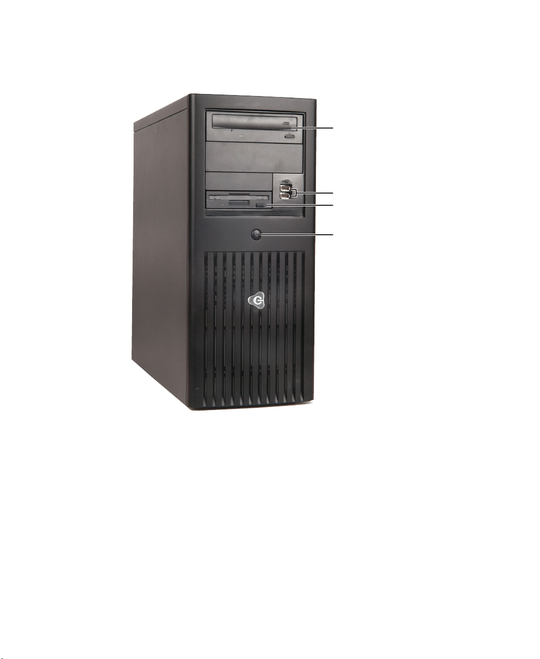
Front
CD or DVD driv
USB ports
Diskette drive
Power button
2
www.gateway.com
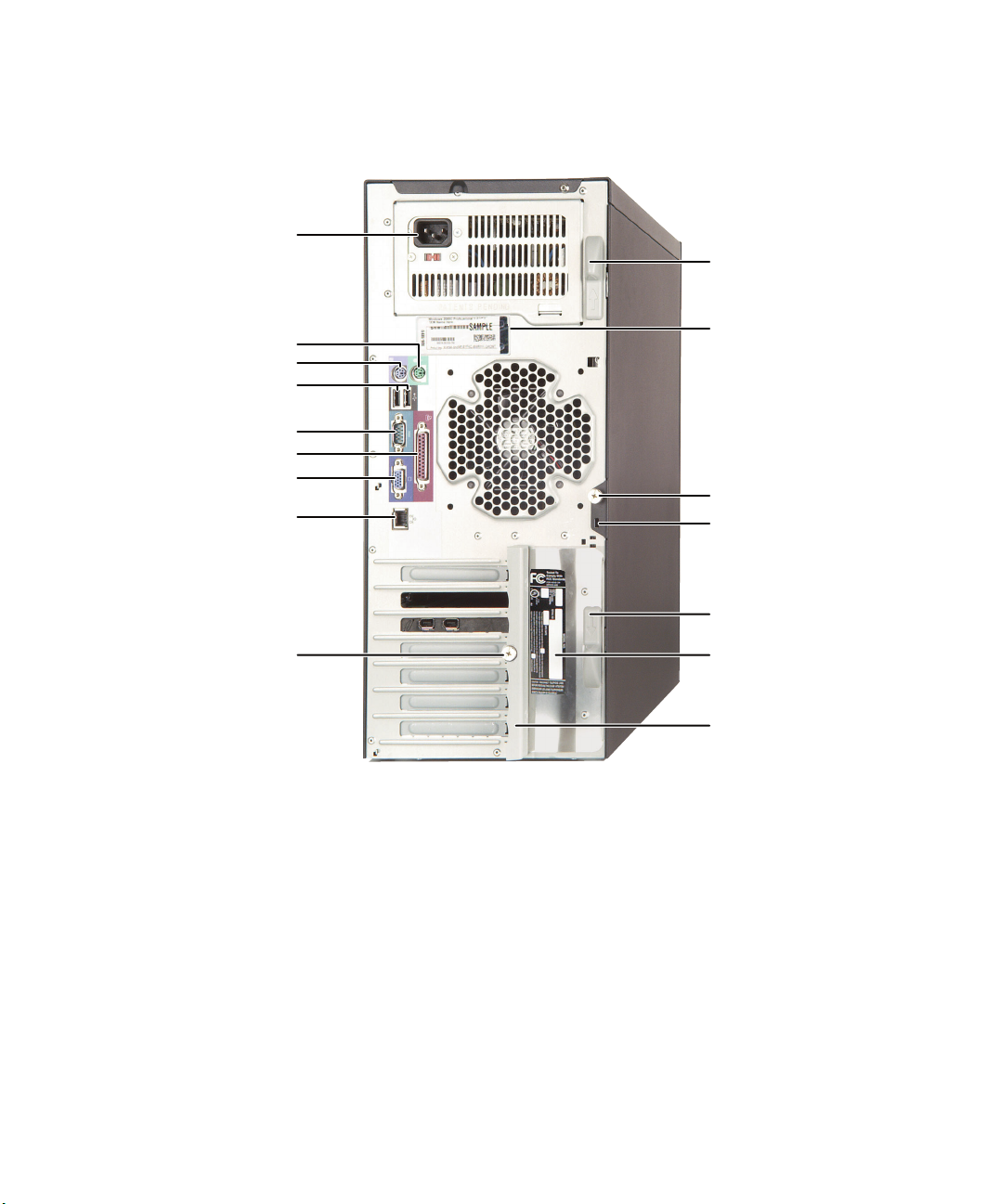
Back
Power connector
Mouse port
Keyboard port
USB ports
Serial port
Parallel port
Monitor port
LAN jack
Back
Release latch
Microsoft
Certificate of
Authenticity
Shipping
thumbscrew
Kensington
lock slot
Card retention
cover thumbscrew
www.gateway.com
Release latch
System label
Card retention
cover
3
Chapter 1: Checking Out Your Gateway Server
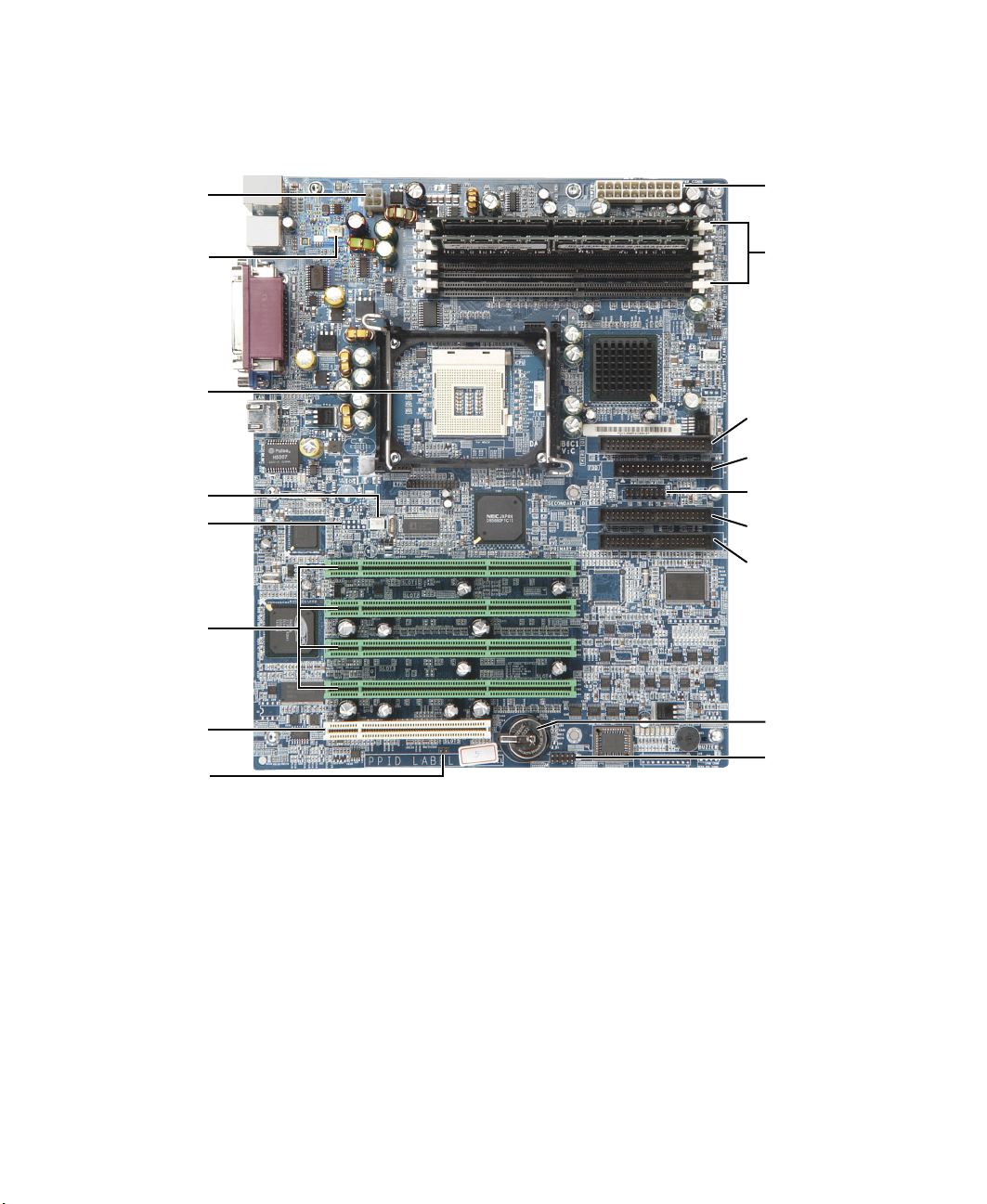
System board
Auxiliary
power
connector
Rear fan
connector
Main power
connector
Memory
module slots
Processor
slot
Processor fan
connector
Front panel
USB connector
64-bit PCI slots
32-bit PCI slot
Intrusion
switch
connector
Third IDE
connector
Diskette drive
connector
Front panel
connector
Primary IDE
connector
Secondary IDE
connector
CMOS battery
Configuration
jumper J13
4
www.gateway.com

Getting Help
In addition to your operating system’s documentation, there are additional
information resources available to help you use your server.
Server Companion CD
Use the Server Companion CD to access file utilities and documentation for your
server and its components. For more information, see Using Your Server
Companion CD.
Gateway Web site
Gateway provides a variety of information on its Web site to help you use your
server.
Getting Help
Visit the Gateway Web site at support.gateway.com
■ Technical documentation and product guides
■ Technical tips and support
■ Updated hardware drivers
■ Order status
■ Frequently asked questions (FAQs)
for:
Telephone support
You can access a wide range of services through your telephone, including
customer service, technical support, and information services. For more
information, see “Telephone support” on page 64.
www.gateway.com
5

Chapter 1: Checking Out Your Gateway Server
6
www.gateway.com

Setting Up Your
Server
Read this chapter to learn how to:
■ Use your server safely
■ Start and turn off your server
■ Restart (reboot) your server
■ Set up your operating system
2
7

Chapter 2: Setting Up Your Server
Setting up the hardware
To make sure that your working environment is safe:
■ Use a clean, dry, flat, stable surface for your server. Allow at least 6 inches
at the rear of the server for cabling and air circulation.
■ Use the instructions on your server’s setup poster to set up your hardware.
■ Use an uninterruptable power supply (UPS) with surge protection for
protection from power outages and power spikes.
Warning Your server comes with a 3-wire AC power cord fitted with
the correct plug style for your region. If this plug does not
match the connector on your UPS or wall outlet, do not
attempt to modify the plug in any way. Use a UPS or wall
outlet that is appropriate for the supplied AC power cord.
■ Avoid subjecting your server to extreme temperature changes. Do not
expose your server to direct sunlight, heating ducts, or other
heat-generating objects. Damage caused by extreme temperatures is not
covered by your warranty. As a general rule, your server is safest at
temperatures that are comfortable for you.
■ Keep your server and magnetic media away from equipment that generates
magnetic fields, such as unshielded stereo speakers. Strong magnetic fields
can erase data on both diskettes and hard drives. Even a telephone placed
too close to the server may cause interference.
Important Keep the server boxes and packing material in case you
need to send the server to Gateway for service. If you
return your server in different packaging, your warranty
may be voided.
8
www.gateway.com

Protecting from power source problems
Protecting from power source
problems
Lne conditioners and uninterruptible power supplies can help protect your
server against power source problems.
Line conditioners
A line conditioner protects your server from the small fluctuations in voltage
from an electrical supply. Most servers can handle this variation, called line
noise, without problems. However, some electrical sources include more line
noise than normal. Line noise can also be a problem if your server is located
near, or shares a circuit with, a device that causes electromagnetic interference,
such as a television or a motor.
Some uninterruptible power supplies include simple line-conditioning
capabilities.
Uninterruptible power supplies
Use an uninterruptible power supply (UPS) to protect your server from data loss
during a total power failure. A UPS uses a battery to keep your server running
temporarily during a power failure and lets you save your work and shut down
your server. You cannot run your server for an extended period of time while
using only the UPS. Be sure to use a UPS with surge protection. To buy a UPS,
contact Gateway Technical Support, Gateway Sales, visit
accessories.gateway.com
support, see “Telephone support” on page 64
. For more information on contacting technical
www.gateway.com
9
Chapter 2: Setting Up Your Server
Starting your server
Before you start your server for the first time:
■ Make sure that the server and monitor are plugged into a power outlet or
UPS and that the UPS (if you are using one) is turned on.
■ Make sure that all cables are firmly connected to the correct ports and jacks
on the back of the server.
Warning When you connect peripheral devices to the server, make
sure that your server and devices are turned off and the
power cords are unplugged.
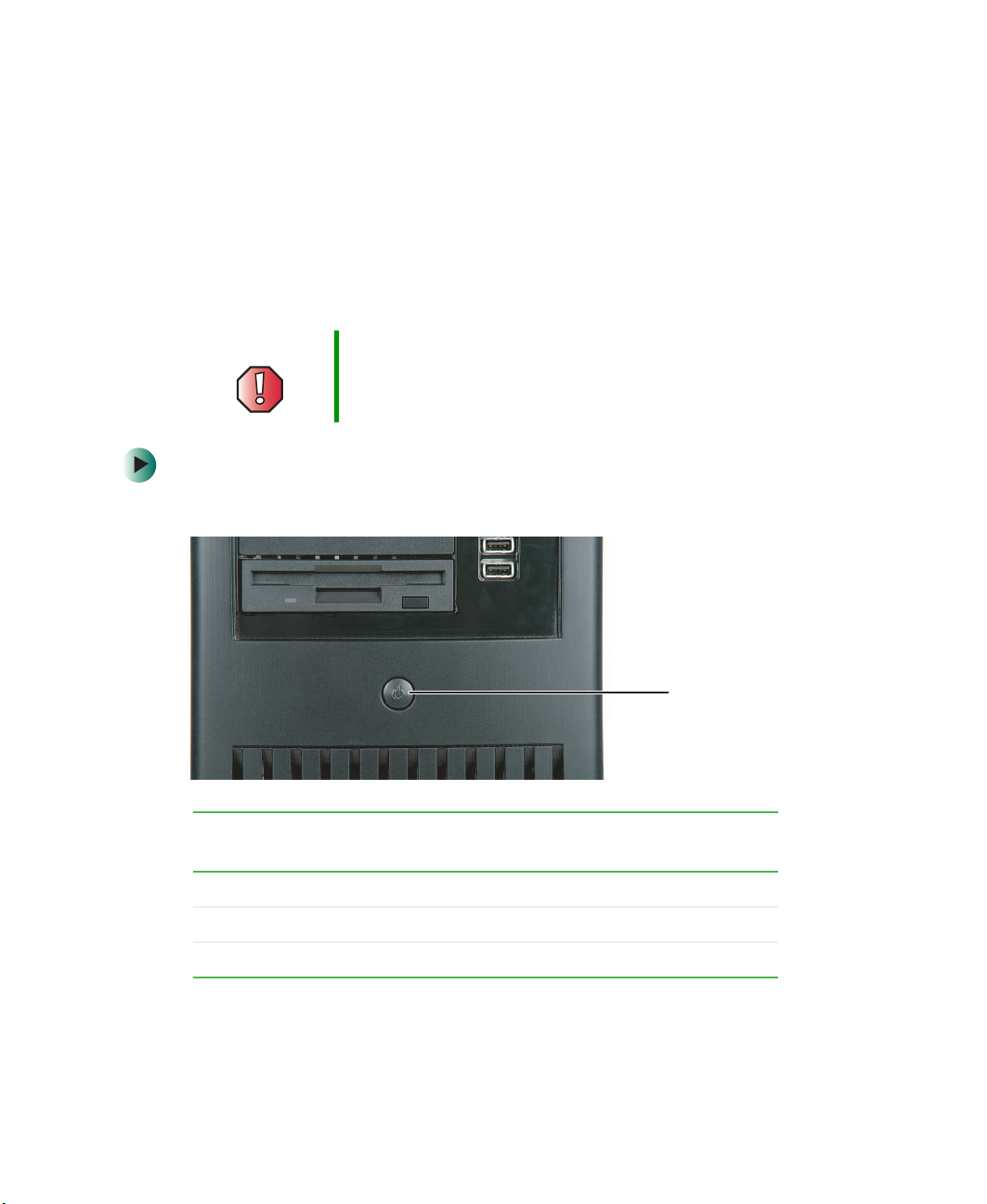
To start the server:
1 Press the power button.
10
When the power
button LED is...
Green The server is turned on.
Orange The server is in Standby.
Off The server is turned off.
It means...
www.gateway.com
Power button

If nothing happens when you press the power button:
■ Make sure that the power cord is plugged in securely and that your
UPS (if you are using one) is plugged in and turned on.
■ Make sure that the monitor is connected to the server, plugged into
the power outlet or UPS, and turned on. You may also need to adjust
the monitor’s brightness and contrast controls.
2 The first time you turn on the server, any pre-installed operating system
may begin asking you for configuration settings. See your operating
system’s documentation for instructions on configuring advanced settings
for your specific network.
Understanding the power-on self-test
When you turn on your server, the power-on self-test (POST) routine checks
the server memory and components. If POST finds any problems, the server
displays error messages. Write down any error messages that you see, then see
“Error messages” on page 68 and “Beep codes” on page 71 for troubleshooting
information.
Starting your server
www.gateway.com
11

Chapter 2: Setting Up Your Server
Turning off your server
Every time you turn off your server, first shut down the operating system. You
may lose data if you do not follow the correct procedure.
To turn off the server:
1 See the operating system’s documentation or online help for instructions
on shutting down the operating system. Whenever possible, you should
use the operating system’s shut down procedure instead of pressing the
power button.
2 If your server did not turn off automatically, press the power button. If
nothing happens when you press the power button, press and hold it for
five seconds and the server will turn off.
Warning The power button on the server does not turn off server
AC power. To remove AC power from the server, you must
unplug the AC power cord from the wall outlet or power
source. The power cord is considered the disconnect
device to the main (AC) power.
12
Warning If you routinely turn off your server (daily or weekly), do
not unplug the server or use the On/Off switch on the UPS.
Regularly cutting off all power to your server may cause
the CMOS battery to fail prematurely.
www.gateway.com

Setting up the operating system
Setting up the operating system
If you ordered your server with the operating system already installed by
Gateway, it is completely installed and the basic settings are already configured.
See your operating system’s documentation or online help for instructions on
configuring advanced settings for your specific network.
If you are installing an operating system because it was not already installed
by Gateway, see the appropriate installation guide for instructions.
www.gateway.com
13

Chapter 2: Setting Up Your Server
14
www.gateway.com

Maintaining Your
Server
Read this chapter to learn how to:
■ Care for your server
■ Record the BIOS configuration
■ Manage your server and network
3
15

Chapter 3: Maintaining Your Server
Caring for your server
To extend the life of your server:
■ Be careful not to bump or drop your server.
■ When transporting your server, we recommend that you put it in the
original packaging materials.
■ Keep your server and magnetic media away from equipment that generates
magnetic fields.
■ Avoid subjecting your server to extreme temperatures. Do not expose your
server to heating ducts or other heat-generating objects. Damage caused
by extreme temperatures is not covered by your warranty. As a general rule,
your server is safest at temperatures that are comfortable for you.
■ Keep all liquids away from your server. When spilled onto server
components, almost any liquid can result in extremely expensive repairs
that are not covered under your warranty.
■ Avoid dusty or dirty work environments. Dust and dirt can clog the
internal mechanisms and can cause the server to overheat.
Cleaning your server
Keeping your server clean and the vents free from dust helps keep your server
performing at its best. Your server cleaning kit could include:
■ A soft, lint-free cloth
■ Glass cleaner
■ An aerosol can of air with a narrow, straw-like extension
■ Isopropyl alcohol
■ Cotton swabs
■ A tape drive cleaning cartridge (if a tape drive is installed)
■ A CD or DVD drive cleaning kit
16
www.gateway.com

Caring for your server
Cleaning tips
■ Always turn off your server and other peripheral devices before cleaning
any components.
Warning When you shut down your server, the power turns off, but
some electrical current still flows through your server. To
avoid possible injury from electrical shock, unplug the
power cord and all other cables connected to the server.
■ Use a damp, lint-free cloth to clean your server and other parts of your
server system. Do not use abrasive or solvent cleaners because they can
damage the finish on components.
■ Keep the cooling vents free of dust. With your server turned off and
unplugged, brush the dust away from the vents with a damp cloth, but
be careful not to drip any water into the vents.
Cleaning the keyboard
You should clean the keyboard occasionally by using an aerosol can of air with
a narrow, straw-like extension to remove dust and lint trapped under the keys.
If you spill liquid on the keyboard, turn off your server and turn the keyboard
upside down to let the liquid drain. Let the keyboard dry completely before
trying to use it again. If the keyboard does not work after it dries, you may
need to replace it. Keyboard damage resulting from spilled liquids is not covered
by your warranty.
Cleaning the screen
If your computer screen is a flat panel display, use only a damp, soft cloth to
clean it. Never spray water directly onto the screen.
Warning The computer screen is made of specially coated glass
and can be scratched or damaged by abrasive or
ammonia-based glass cleaners.
- OR -
If your computer screen is not a flat panel display, use a soft cloth dampened
with glass cleaner to clean the screen. Never spray cleaner directly onto the
screen.
www.gateway.com
17

Chapter 3: Maintaining Your Server
Cleaning the tape drive
If you use a tape drive to back up your files, regular maintenance will lengthen
the life of the drive. To maintain the drive’s reliability:
■ Clean the drive monthly with the cleaning cartridge included with
the drive.
■ Remove the tape from the drive whenever the drive is not in use.
18
www.gateway.com

Preparing for system recovery
Preparing for system recovery
If your system files are corrupted, you may not be able to start the server from
the hard drive. Startup diskettes are diskettes that let you start the server and
attempt to fix the problem. See your operating system’s documentation or
online help for instructions on creating startup diskettes.
Some operating systems also let you create an emergency repair diskette to back
up critical operating system files. See your operating system’s documentation
or online help for instructions on using an emergency repair diskette.
Recording the BIOS configuration
To help keep track of your custom changes to BIOS settings and to prepare for
system recovery, you should record your BIOS configuration after you have your
server set up and working.
To record your BIOS configuration:
1 Print the appendix for BIOS Settings in this guide.
2 Restart your server, then press F2 when the Gateway logo screen appears
during startup. The BIOS Setup utility opens.
3 Record the BIOS settings on your printout.
www.gateway.com
19

Chapter 3: Maintaining Your Server
System administration
Gateway Server Manager
Gateway Server Manager lets you manage multiple computers on a Windows
network from a single window, then implement commands and policies across
the network with a single action. With Gateway Server Manager, you can run
system management tasks which are triggered by certain events or conditions.
Printed documentation comes with the Gateway Server Manager CD. You can
find additional documentation in the program’s online help.
Server security
To prevent unauthorized use of the server, you can set BIOS startup passwords.
Using BIOS security passwords
Set up a supervisor password to prevent unauthorized access to the BIOS Setup
utility. After you create a supervisor password, you can set up a user password
to prevent unauthorized access to the server. You can:
■ Enter either password to finish starting the server.
■ Enter the supervisor password to access the BIOS Setup utility.
For information about resetting BIOS passwords, see “Bypassing the BIOS
passwords” on page 61.
To set the BIOS security passwords:
1 Restart your server, then press F2 when the Gateway logo screen appears
during startup. The BIOS Setup utility opens.
2 Select the Security menu.
20
www.gateway.com

System administration
3 Select the password to set according to the following table.
Option Description
Supervisor password To control access to system configuration, set a
supervisor password. Using a supervisor password lets
you make changes to any setting in the BIOS.
Passwords can be cleared. To clear the passwords, see
“Bypassing the BIOS passwords” on page 61.
User password The supervisor password must be set up before a user
password can be set. To control access to the server, set
a user password. The supervisor can set the level of
access granted to the user password. The user password
access levels are:
■
No Access. User cannot access the BIOS Setup utility.
■
Limited. User can change only the date and time.
■
View Only. User can see all settings, but cannot
change them.
■
Full. User can change every setting except the
supervisor password.
Passwords can be cleared. To clear the passwords, see
“Bypassing the BIOS passwords” on page 61.
4 Type the password and press ENTER, then type it again and press ENTER.
5 Save your changes, then close the BIOS Setup utility.
www.gateway.com
21

Chapter 3: Maintaining Your Server
Using your Server Companion CD
You can use your Server Companion CD to:
■ Install hardware drivers
■ Install programs
■ View server documentation
Instructions for using the CD are provided in Using Your Server Companion CD.
22
www.gateway.com

Installing
Components
Read this chapter to learn how to:
■ Open and close the server case
■ Install drives
■ Install memory modules
■ Install expansion cards
■ Replace the processor
■ Replace the power supply
■ Replace the system board
■ Replace the rear case fan
■ Replace the CMOS battery
You must open your server case to install components. If
you are not comfortable with these procedures, get help
from a more experienced computer user or computer
service technician, or contact Gateway Technical Support.
4
23

Chapter 4: Installing Components
Preparing to install components
Selecting a place to work
Work on your server in an area that:
■ Is clean (avoid dusty areas)
■ Is a low-static environment (avoid carpeted areas)
■ Has a stable surface on which to set your server
■ Has enough room to place all of your server parts
■ Is near a grounded outlet so you can test your server after installation
■ Is near a telephone (in case you need help from Gateway Technical
Support). The telephone must be directly connected to a telephone jack
and cannot be connected to your server.
Gathering the tools you need
Some tools and supplies that you may need to work on your server are:
■ A notebook to take notes
■ A Phillips screwdriver
■ A small flat-blade screwdriver
■ Small containers to store various types of screws
■ A grounding wrist strap (available at most electronic stores)
24
www.gateway.com

Preventing static electricity discharge
Preventing static electricity
discharge
The components inside your server are extremely sensitive to static electricity,
also known as electrostatic discharge (ESD).
Warning ESD can permanently damage electrostatic
discharge-sensitive components in the server. Prevent
ESD damage by following ESD guidelines every time you
open the server case.
Warning To avoid exposure to dangerous electrical voltages and
moving parts, turn off your server and unplug the power
cord and modem cable before opening the server case.
Before working with server components, follow these guidelines:
■ Turn off the server, then unplug the power cord and all other cables.
■ Press the power button to drain any residual power from the server.
■ Wear a grounding wrist strap (available at most electronics stores) and
attach it to a bare metal part of the server. You can also touch a bare metal
surface on the back of the server with your finger.
Warning To prevent risk of electric shock, do not insert any object
into the vent holes of the power supply.
■ Avoid static-causing surfaces such as carpeted floors, plastic, and packing
foam.
■ Avoid working on the server when your work area is extremely humid.
■ Remove components from their antistatic bags only when you are ready
to use them. Do not lay components on the outside of antistatic bags
because only the inside of the bags provide electrostatic protection.
■ Always hold expansion cards by their edges or their metal mounting
brackets. Avoid touching the edge connectors and components on the
cards. Never slide expansion cards or components over any surface.
www.gateway.com
25

Chapter 4: Installing Components
Opening the server case
Because the components inside your server are extremely sensitive to static
electricity, make sure that you follow the instructions at the beginning of this
chapter to avoid static electricity damage.
Warning For correct cooling and air flow, always reinstall the side
panel before you turn on the server. Operating the server
without the cover in place can damage server components.
To open the server case:
1 Follow the instructions in “Preventing static electricity discharge” on
page 25.
2 Turn off the server, then disconnect the power cord and all other cables
connected to the server.
3 For more stability, place the server on its side.
4 If your case has a shipping thumbscrew installed on the back, remove the
screw, then push the cover release latches away from each other.
26
Shipping thumbscrew
www.gateway.com

5 Swing the side panel away from the case.
Opening the server case
www.gateway.com
27

Chapter 4: Installing Components
Closing the server case
To close the server case:
1 For more stability, place the server on its side.
2 Make sure that all of the internal cables are arranged inside the case so
they will not be pinched when you close the server case.
3 Align the side panel’s front tabs into the case notches, then swing the side
panel toward the case until the release latches snap into place.
4 Set the case upright.
5 Reconnect the power cord and all other cables.
28
www.gateway.com

Installing drives
Your server comes with a CD or DVD drive and a 3.5-inch diskette drive. Your
server also has one additional 5.25-inch drive bay and one additional 3.5-inch
drive bay.
CD or DVD drive
5.25-inch drive bay
3.5-inch drive bay
3.5-inch diskette drive
Installing drives
As you prepare to install drives, remember:
■ Before you install a drive, see the drive’s documentation for information
on configuring the drive, setting drive jumpers, and attaching cables.
■ If you are installing a drive that requires a controller card, you must install
the card before the drive will work.
www.gateway.com
29

Chapter 4: Installing Components
■ IDE hard drives can be configured as single, master, slave, or cable-select.
IDE CD or DVD drives can be configured as master, slave, or cable-select.
■ If cable-select is available (drive assignments will be marked on the
cable), the IDE cable assigns the master/slave positions to the drives
it connects. You can override these assignments using the jumpers on
the drives.
■ If cable-select is not available and only one drive is attached to an IDE
controller cable, configure the drive as master if it is a CD or DVD
drive. If two drives of any type are attached to the cable, configure
one as master and one as slave.
■ If you are connecting two IDE drives to the cable, connect the middle
cable connector to the slave drive and connect the end cable
connector to the master (boot) drive.
■ You may need to configure the drives you install using the BIOS Setup
utility. Press F2 at startup to open the BIOS Setup utility.
Installing a CD, DVD, or diskette drive
Important Drives connected to the primary and secondary IDE
connectors should be ATA100 drives, and drives
connected to the third IDE connector should be ATA66
drives.
To install a CD, DVD, or diskette drive:
1 Follow the instructions in “Preventing static electricity discharge” on
page 25.
2 Follow the instructions in “Opening the server case” on page 26.
30
www.gateway.com

Installing drives
3 If you are replacing a drive, go to Step 6.
- OR -
If you are adding a new drive, press in on the two front cover release tabs,
then swing the front cover away from the server and remove the cover.
4 Press the drive bay face plate release tab, then swing the faceplate away
from the front cover and remove the face plate.
www.gateway.com
31

Chapter 4: Installing Components
5 Remove the shield for the bay into which you are installing the new drive.
Shields
32
6 If you are replacing a drive, disconnect the drive cables.
7 If there is a shipping thumbscrew installed next to the drive release latch,
remove the thumbscrew.
Shipping thumbscrew
www.gateway.com

Installing drives
8 Slide the drive release latch back toward the rear of the case until the unlock
icon is visible.
Unlock icon
9 If you are replacing a drive, slide it forward and out of the drive bay.
10 Set any jumpers on the new drive. See the drive’s documentation for further
instructions.
11 Slide the new drive into the drive bay.
12 Move the release latch to the right about ¼ inch (6 mm).
www.gateway.com
33

Chapter 4: Installing Components
13 Align the drive’s screw holes with the release latch’s locking tabs.
14 Slide the drive release latch toward the front of the case until the lock icon
is visible.
Locking tabs
Drive screw
holes
Lock icon
15 Follow the instructions in the drive’s documentation to connect the drive
cables.
34
www.gateway.com

16 If you removed the front cover, replace it.
17 Follow the instructions in “Closing the server case” on page 28.
Installing a hard drive
Important Drives connected to the primary and secondary IDE
connectors should be ATA100 drives, and drives
connected to the third IDE connector should be ATA66
drives.
To install a hard drive:
1 Follow the instructions in “Preventing static electricity discharge” on
page 25.
2 Follow the instructions in “Opening the server case” on page 26.
3 If you are replacing a hard drive, disconnect the old drive’s cables.
Installing drives
4 Slide the drive release latch toward the open side of the case.
www.gateway.com
35

Chapter 4: Installing Components
5 If you are replacing a hard drive, slide the old drive out of the drive bay.
6 Set any jumpers on the new drive. See the drive’s documentation for further
instructions.
36
7 Slide the new drive in, then slide the release latch toward the inside of
the case.
www.gateway.com

Installing drives
8 Follow the instructions in the drive’s documentation to connect the drive
cables.
9 Follow the instructions in “Closing the server case” on page 28.
www.gateway.com
37

Chapter 4: Installing Components
Installing memory
When you upgrade your server memory, make sure that you install the correct
type of memory module for your server. Your server uses PC2100 DDR SDRAM
registered ECC DIMM memory. The following illustration shows the location
of the memory modules on the system board.
Warning Use only PC2100 DDR SDRAM registered ECC DIMM
memory modules.
Memory
module slots
38
www.gateway.com

Installing memory
To install or replace memory:
1 Follow the instructions in “Preventing static electricity discharge” on
page 25.
2 Follow the instructions in “Opening the server case” on page 26.
3 Pull the plastic tabs away from the sides of the memory module slot. If
you are replacing a memory module, remove the old module.
4 Align the notch on the new module with the notch in the memory module
slot and press the module firmly into the slot. The tabs on the sides of
the memory slot should secure the memory module automatically.
5 Follow the instructions in “Closing the server case” on page 28.
6 Turn on the server. Make sure that the server turns on and that the
operating system loads completely.
7 Restart your server and open the BIOS Setup utility. Verify the amount of
memory installed with the
System Memory listed in the Main menu.
www.gateway.com
39

Chapter 4: Installing Components
Installing PCI expansion cards
A PCI expansion card (sometimes called an add-in card) is a card used in the server
to add functionality to the system. Use the following procedure to replace, add,
or reseat an expansion card.
To replace, add, or reseat a PCI expansion card:
1 Follow the instructions in “Preventing static electricity discharge” on
page 25.
2 Follow the instructions in “Opening the server case” on page 26.
3 If you are replacing a card, disconnect any cables that are attached to the
old card.
4 Remove the thumbscrew that secures the expansion card retention cover
to the server case.
40
Thumbscrew
www.gateway.com

Installing PCI expansion cards
5 While holding the retention cover open, remove the expansion card. You
can slightly seesaw the card end-to-end to loosen the card, but do not bend
the card sideways.
Warning Do not touch the contacts on the bottom part of the
expansion card. Touching the contacts can cause
electrostatic damage to the card.
6 While holding the retention cover open, press the new card into the
expansion slot. You can slightly seesaw the card end-to-end to help insert
the card, but do not bend the card sideways.
7 Push the retention cover in, then tighten the thumbscrew.
8 Connect any cables to the card. For more information, see the card’s
documentation.
9 Follow the instructions in “Closing the server case” on page 28.
10 See the card’s documentation for software installation instructions.
www.gateway.com
41

Chapter 4: Installing Components
Replacing the processor
Your server is compatible with the Intel® Pentium®4 or Intel® Celeron®
processor. The server automatically detects the processor each time you turn
on the server. Whenever you install a new processor, you should first install
the most current version of the BIOS. For more information, see “Updating the
BIOS” on page 57.
Warning A heat sink must be installed on the processor. Installing
a processor without a heat sink could damage the
processor.
Warning The processor and heat sink may be hot if the computer
has been running. Also, there may be sharp edges on the
heat sink. Consider wearing protective gloves.
To replace the processor:
1 Install the most current BIOS version. For more information, see “Updating
the BIOS” on page 57.
42
2 Follow the instructions in “Preventing static electricity discharge” on
page 25.
3 Follow the instructions in “Opening the server case” on page 26.
www.gateway.com

Replacing the processor
4 Unplug the heat sink’s cooling fan from the system board.
5 Press down on the heat sink locking lever on each side, push them slightly
away from the heat sink, then lift the levers out of the way.
6 Remove the heat sink.
Important The heat sink mounting paste may harden over time and
hold the heat sink securely to the processor. If removing
the heat sink also pulls the processor out of the processor
socket, the processor should still be undamaged. Continue
with the procedure.
www.gateway.com
43

Chapter 4: Installing Components
7 Press down on the processor locking lever, push it slightly away from the
processor, then rotate the lever straight up to release the processor.
8 Remove the old processor.
9 Install the new processor into the processor slot. Make sure that the arrow
on the corner of the processor aligns with Pin 1 on the processor socket
(the socket corner without a pin hole).
10 Press the processor locking lever down until it clicks into place.
11 Apply thermal grease to the top of the processor, if necessary.
12 Place the heat sink on the processor, then press the heat sink locking levers
down until they click into place.
13 Plug the heat sink’s cooling fan into the system board.
14 Follow the instructions in “Closing the server case” on page 28.
44
www.gateway.com

Replacing the power supply
Replacing the power supply
Warning The power supply in this server contains no
user-serviceable parts. Only a qualified computer
technician should service the power supply.
Your server comes with a 3-wire AC power cord fitted with
the correct plug style for your region. If this plug does not
match the connector on your UPS or wall outlet, do not
attempt to modify the plug in any way. Use a UPS or wall
outlet that is appropriate for the supplied AC power cord.
To replace the power supply:
1 Follow the instructions in “Preventing static electricity discharge” on
page 25.
2 Follow the instructions in “Opening the server case” on page 26.
3 Disconnect the power supply cables from all components, noting their
locations and orientation. (You will reconnect the cables after you install
the new power supply.)
4 Pull the power supply retention clip away from the power supply.
www.gateway.com
45

Chapter 4: Installing Components
5 While supporting the power supply with your hand, slide the power supply
toward the front of the case, then out toward the bottom of the case.
6 Install the new power supply, then press the retention clip back against
the case.
46
7 Reconnect the power supply cables.
8 Follow the instructions in “Closing the server case” on page 28.
www.gateway.com

Replacing the system board
Replacing the system board
To replace the system board:
1 Follow the instructions in “Preventing static electricity discharge” on
page 25.
2 Follow the instructions in “Opening the server case” on page 26.
3 Remove all of the expansion cards. For more information, see “Installing
PCI expansion cards” on page 40.
4 Remove the heat sink and processor. For more information, see “Replacing
the processor” on page 42.
5 Remove the memory modules. For more information, see “Installing
memory” on page 38.
6 Disconnect the power and data cables from the system board, noting their
locations and orientation. (You will reconnect the cables after you install
the new board.) Make sure that you disconnect the intrusion switch cable.
7 Remove the system board’s thumbscrew.
www.gateway.com
ThumbscrewIntrusion switch connector
47

Chapter 4: Installing Components
8 Slide the system board toward the front of the case, then lift it away from
the case.
9 Slide the new system board’s standoffs into the keyhole slots, then slide
the board toward the back of the case.
Important The new system board must have special standoffs
pem studs
(
necessary, use the standoffs from the original system
board.
) mounted on the bottom of the board. If
10 Lock the system board into place with the thumbscrew.
48
www.gateway.com
Standoff
Keyhole slot

Replacing the system board
11 Install the memory, processor, and heat sink, then reconnect the heat sink
cooling fan to the system board.
12 Connect the power and data cables.
13 Install the expansion cards. For more information, see “Installing PCI
expansion cards” on page 40.
14 Follow the instructions in “Closing the server case” on page 28.
15 Turn on your server.
16 Press F2 when the Gateway logo screen appears during startup. The BIOS
Setup utility opens.
17 Check BIOS settings to make sure that they detect the server’s new
hardware, then save your changes (if any) and close the BIOS Setup utility.
www.gateway.com
49

Chapter 4: Installing Components
Replacing the case fan
To replace the case fan:
1 Follow the instructions in “Preventing static electricity discharge” on
page 25.
2 Follow the instructions in “Opening the server case” on page 26.
3 Unplug the case fan from the system board.
Rear fan connector
50
4 Use a narrow tool, such as a small screwdriver, to push each of the four
fan mounting rivets and sleeves out toward the back of the case.
www.gateway.com

Replacing the case fan
5 Remove each rivet, then remove the old fan.
6 Hold the new fan in place while you push the fan’s rivet sleeves into the
fan from the outside of the case, then push the rivets into the sleeves.
7 Reconnect the case fan to the system board.
8 Follow the instructions in “Closing the server case” on page 28.
www.gateway.com
51

Chapter 4: Installing Components
Replacing the CMOS battery
If the server clock does not keep time or the settings in the BIOS Setup utility
are not saved when you turn off the server, replace the CMOS battery with an
equivalent battery.
Warning Danger of explosion if battery is incorrectly replaced.
Replace only with the same or equivalent type
recommended by the manufacturer. Dispose of used
batteries following the manufacturer’s instructions.
To replace the battery:
1 Print the appendix for BIOS Settings in this guide.
2 Restart your server.
3 Press F2 when the Gateway logo screen appears during startup. The BIOS
Setup utility opens.
4 Record the BIOS settings on your printout, then close the utility.
52
5 Turn off your server, then follow the instructions in “Preventing static
electricity discharge” on page 25.
6 Follow the instructions in “Opening the server case” on page 26.
7 Locate the old battery on the system board and note its orientation. You
will need to install the new battery the same way.
Battery
www.gateway.com

Replacing the CMOS battery
8 Place the edge of a small flat-head screwdriver under the battery and lift
the battery up until it comes out of the socket.
9 Make sure that the positive (+) side of the new battery is facing up, then
press the new battery into the socket until it snaps into place.
10 Follow the instructions in “Closing the server case” on page 28.
11 Turn on t he server.
12 Press F2 when the Gateway logo screen appears during startup. The BIOS
Setup utility opens.
13 Restore any BIOS settings that you wrote down in Step 4.
14 Save all your settings and close the BIOS Setup utility.
www.gateway.com
53

Chapter 4: Installing Components
54
www.gateway.com

Using the BIOS
Setup Utility
Read this chapter to learn how to:
■ Open the BIOS Setup utility
■ Update the BIOS
■ Reset the BIOS settings to their factory defaults
■ Bypass the BIOS passwords
5
55

Chapter 5: Using the BIOS Setup Utility
Opening the BIOS Setup utility
The BIOS Setup utility stores basic settings for your server. These settings include
basic hardware configuration, resource settings, and password security. These
settings are stored and saved even when the power is off.
Caution The options in the BIOS Setup utility have been set at the
factory for optimal performance. Changes to these
settings will affect the performance of your server.
Before changing any settings, write them down in case you
need to restore them later. You can record the settings on
a printout of the appendix for “BIOS Settings” on page 97.
To open the BIOS Setup utility:
1 Restart your server.
2 Press F2 when the Gateway logo screen appears during startup. The BIOS
Setup utility opens.
56
When you select menu items, the Item Specific Help box on the right side
of the screen displays specific information about the selection. The
command bar across the bottom of the screen shows the keys you press
to access help, navigate through the menus, and perform other tasks.
3 Select one of these menus:
■ Main gives you access to basic information and settings related to your
server’s hardware and configuration.
■ Advanced gives you access to information and settings for system
resources, hardware, and server’s configuration.
■ Power gives you access to settings that control your server’s power
management features.
■ Boot lets you change startup settings.
■ Security gives you access to settings related to system access passwords.
For more information, see “Server security” on page 20.
■ Exit gives you access to options for closing the BIOS Setup utility.
www.gateway.com

Updating the BIOS
If you need a new version of the BIOS, you can download the BIOS update from
Gateway, then install the new version from a diskette.
To update the BIOS:
1 Print the appendix for BIOS Settings in this guide.
2 Download the BIOS update from support.gateway.com.
3 Restart your server.
4 Press F2 when the Gateway logo screen appears during startup.
5 Record any custom BIOS settings on your printout.
6 Follow the instructions in the self-extracting BIOS update file.
7 Enter any custom BIOS settings you recorded in Step 5, then save your
changes and close the BIOS Setup utility.
Updating the BIOS
Recovering the BIOS
If you encounter a problem while you are updating the BIOS, such as a power
outage, the BIOS update may not be successful. You can recover the old BIOS
so you can try another update.
To recover the BIOS:
1 Follow the instructions in “Preventing static electricity discharge” on
page 25.
2 Turn off the server, then disconnect the power cord and all other cables
connected to the server.
3 Remove the side panel. For more information, see “Opening the server
case” on page 26.
www.gateway.com
57

Chapter 5: Using the BIOS Setup Utility
Warning Moving the jumper while the power is on can damage your
server. Always turn off the server and unplug the power
cord and all other cables before changing the jumper.
4 Place the jumper across pins 5-6 of jumper J13.
5 Close the case, then reconnect the power cord, monitor, and keyboard. For
more information, see “Closing the server case” on page 28.
Jumper pins 5-6
6 Place the startup diskette containing the BIOS files into drive A.
7 Turn on the server. At the start of the BIOS recovery process, the server
beeps once. The recovery process may take a few minutes.
8 When prompted, remove the diskette and turn off the server.
9 Disconnect the power cord and remove the side panel again. Remove the
jumper from pins 5-6 of jumper J13, and place it over just one of the pins
for storage.
10 Close the case, reconnect the power cord and all other cables, then turn
on the server.
11 When the Gateway Logo screen appears, press F2 to open the BIOS Setup
utility.
12 In the BIOS Setup utility, go to the appropriate menus and select any BIOS
fields you want to change. Make sure that the date and time are correct.
13 Save your changes, then close the BIOS Setup utility.
58
www.gateway.com

Resetting the BIOS
The Reset BIOS jumper on the system board lets you return all BIOS settings
to the factory defaults.
To reset the BIOS:
1 Print the appendix for BIOS Settings in this guide.
2 Restart your server.
3 Press F2 when the Gateway logo screen appears during startup. The BIOS
Setup utility opens.
4 Record any custom BIOS settings on your printout.
5 Follow the instructions in “Preventing static electricity discharge” on
page 25.
6 Turn off the server, then disconnect the power cord and all other cables
connected to the server.
7 Remove the side panel. For more information, see “Opening the server
case” on page 26.
Resetting the BIOS
Warning Moving the jumper while the power is on can damage your
server. Always turn off the server and unplug the power
cord and all other cables before changing the jumper.
8 Place the jumper across pins 3-4 of jumper J13.
Jumper pins 3-4
www.gateway.com
59

Chapter 5: Using the BIOS Setup Utility
9 Close the case, then reconnect the power cord, monitor, and keyboard. For
more information, see “Closing the server case” on page 28.
10 Turn on the server. A message appears saying that the CMOS Checksum
is bad, which means the BIOS has been cleared successfully.
11 Press F2 to load the default BIOS values and open the BIOS Setup utility.
All BIOS settings return to factory defaults, and all BIOS passwords are
erased.
12 Turn off the server, disconnect the power cord, and remove the side panel
again.
13 Remove the jumper from pins 3-4 of jumper J13 and place it over just one
of the pins for storage.
14 Close the case, reconnect the cords, then turn on the server.
60
www.gateway.com

Bypassing the BIOS passwords
Bypassing the BIOS passwords
The Bypass Password jumper on the system board lets you bypass the BIOS
passwords.
To bypass the BIOS passwords:
1 Follow the instructions in “Preventing static electricity discharge” on
page 25.
2 Turn off the server, then disconnect the power cord and all other cables
connected to the server.
3 Remove the side panel. For more information, see “Opening the server
case” on page 26.
Warning Moving the jumper while the power is on can damage your
server. Always turn off the server and unplug the power
cord and all other cables before changing the jumper.
4 Place the jumper across pins 1-2 of jumper J13.
Jumper pins 1-2
5 Close the case, then reconnect the power cord, monitor, and keyboard. For
more information, see “Closing the server case” on page 28.
www.gateway.com
61

Chapter 5: Using the BIOS Setup Utility
6 Turn on the server. You can now open the BIOS Setup utility or perform
other server tasks.
If you want to change the passwords, press F2 when the Gateway logo
screen appears. When the BIOS Setup utility opens, you can clear or change
the passwords, or change other BIOS settings.
7 Turn off the server, disconnect the power cord, and remove the side panel
again.
8 Remove the jumper from pins 1-2 of jumper J13 and place it over just one
of the pins for storage.
9 Close the case, reconnect the cords, then turn on the server.
62
www.gateway.com

Troubleshooting
Read this chapter to learn how to:
■ Get telephone support and training
■ Interpret error messages and codes
■ Troubleshoot
If the suggestions in this chapter do not correct the
problem, see “Telephone support” on page 64 for more
information about how to get help.
6
63

Chapter 6: Troubleshooting
Telephone support
Before calling Gateway Technical Support
If you have a technical problem with your server, follow these
recommendations before contacting Gateway Technical Support:
■ Make sure that your server is connected correctly to a grounded AC outlet
that is supplying power.
■ If a peripheral device, such as a keyboard or mouse, does not appear to
work, make sure that all cables are plugged in securely.
■ If you have recently installed hardware or software, make sure that you
have installed it following the instructions provided with it. If you did not
purchase the hardware or software from Gateway, see the manufacturer’s
documentation and technical support resources.
■ If you have “how to” questions about using a program, see:
■ The program’s online Help
■ The program’s documentation
64
■ Your operating system’s documentation
■ The software or hardware manufacturer’s Web site
■ See “Troubleshooting” on page 70.
■ Have your client ID, serial number (located on the back of your server case),
and order number available, along with a detailed description of your issue,
including the exact text of any error messages, and the steps you have
taken.
■ Make sure that your server is nearby at the time of your call. The technician
may have you follow appropriate troubleshooting steps.
■ Consider using Gateway’s Internet technical support. Gateway’s Web site
has FAQs, tips, and other technical help. You can also use the Web site to
e-mail Technical Support. For more information, visit Gateway’s Technical
Support Web site at support.gateway.com
www.gateway.com
.

Telephone support
Gateway offers a wide range of customer service, technical support, and
information services.
Telephone numbers
You can access the following services through your telephone to get answers
to your questions:
Resource Service description How to reach
Telephone support
Fax on
demand
support
Tu to r i al
support
Gateway
Te ch n i ca l
Support
Sales,
accounting,
and warranty
Order a catalog of documents on common
problems, then order documents by document
numbers. The documents will be faxed to you.
Learn networking tips from Gateway’s tutorial
support on a per-issue fee basis.
Talk to a Gateway Technical Support representative
about a non-tutorial technical support question.
(See “Before calling Gateway Technical Support”
on page 64 before calling.)
TDD Technical Support (for hearing impaired) is
available:
Weekdays 6:00 a.m. - 8:00 p.m. Central Time
Weekends 6:00 a.m. - 5:00 p.m. Central Time
Get information about available systems, pricing,
orders, billing statements, warranty service, or
other non-technical issues.
800-846-4526 (US)
877-709-2951 (Canada)
877-485-1464 (US)
800-846-3609 (Canada
and Puerto Rico)
605-232-2191
(all other countries)
800-846-1778 (TDD)
877-485-1464 (US)
800-846-3609 (Canada
and Puerto Rico)
605-232-2191
(all other countries)
800-846-1778 (TDD)
800-846-2000 (US)
888-888-2037 (Canada)
www.gateway.com
65

Chapter 6: Troubleshooting
Tutoring and training
Gateway's Technical Support professionals cannot provide hardware and
software training. Instead, Gateway recommends the following training
resources.
Resource Service description For more information
In-store training
at Gateway
stores
Gateway
Learning
Libraries
Online training
from
Learn@Gateway
Our friendly and knowledgeable software
trainers can teach you how to use the
Internet and the most popular software
programs, including Microsoft Word,
Excel, and PowerPoint.
A variety of courses and tutorials are
available on CD. Select from several
easy-to-use learning libraries.
More than 450 online courses are
available from Learn@Gateway. All you
have to do is go online and log in. You
select the subject matter and the learning
format (self-paced tutorials or virtual
classrooms), all from the comfort of your
computer.
www.gateway.com/country
www.gateway.com/training
www.learnatgateway.com/
66
www.gateway.com

Safety guidelines
While troubleshooting your server, follow these safety guidelines:
■ Never remove the side panel while your server is turned on and while the
modem cable and the power cord is connected.
■ Do not attempt to open the monitor. To do so is extremely dangerous. Even
if the power is disconnected, energy stored in the monitor components
can be dangerous. Also, opening the monitor voids its warranty.
■ Make sure that you are grounded correctly before opening the server case.
For more information about preventing damage from static electricity, see
“Preventing static electricity discharge” on page 25.
■ After you complete any maintenance task where you have to open the
server case, make sure that you close the case, tighten any screws, then
reconnect all cables before you restart your server.
Warning To avoid bodily injury, do not attempt to troubleshoot your
server problem if:
■
The power cord or plug is damaged
■
Liquid has been spilled into your server
■
Your server was dropped
■
The case was damaged
Instead, unplug your server and contact a qualified
computer technician. If your server was damaged during
shipment from Gateway, contact Gateway Technical
Support.
Safety guidelines
www.gateway.com
67

Chapter 6: Troubleshooting
Error messages
These messages often indicate procedural errors such as typing an incorrect
keystroke or trying to save a file to a write-protected diskette. Some messages,
however, may indicate a problem that requires further troubleshooting.
Diskette drive 0 seek to track 0 failed
■ Restart your server, then press and hold F2 to open the BIOS Setup utility.
Make sure that the drive settings are correct.
Error loading operating system
■ The master boot record may be corrupt. For troubleshooting information,
see “The master boot record is corrupted” on page 76.
Hard disk controller failure
■ Make sure that the hard drive cable is connected securely.
■ Restart your server, then press and hold F2 to open the BIOS Setup utility.
Make sure that the correct drive type is selected.
Hard disk controller failure - press F1 to try reboot
■ The drive controller may be defective. Press F1 to try to restart the server.
For more information about running diagnostics on your hard drive, see
your operating system’s documentation.
■ See “You need to troubleshoot an IDE hard drive” on page 76.
Insert bootable media device
■ Make sure that the correct hard drive is set as the first bootable drive in
the Boot menu of the BIOS Setup utility. Restart your server, then press
and hold F2 to open the BIOS Setup utility.
■ See “Your server does not recognize an IDE drive” on page 75 or “Your
server does not recognize a SCSI drive” on page 75 for a possible solution.
Invalid configuration information
■ Restart your server, then press and hold F2 to open the BIOS Setup utility.
Make sure that the settings are correct.
■ Reset the BIOS. For more information, see “Resetting the BIOS” on page 59.
68
www.gateway.com

Error messages
Invalid partition table
■ The master boot record may be corrupt. For troubleshooting information,
see “The master boot record is corrupted” on page 76.
Invalid password
■ Enter your password again. Some passwords are case sensitive.
■ If you do not know the password, you may need to reinstall the software
you are trying to access.
■ System startup passwords are stored in BIOS. If this password has been set
and you do not know it, you may be able to reset the password through
system board jumper settings. For more information, see “Bypassing the
BIOS passwords” on page 61.
Memory errors were detected while the system started up
■ See “Memory errors were detected during server start up” on page 77 for
a possible solution.
Memory size error
■ Restart your server, then press and hold F2 to open the BIOS Setup utility.
Save the memory configuration.
Missing operating system
■ The master boot record may be corrupt. For troubleshooting information,
see “The master boot record is corrupted” on page 76.
System Event Log Full
■ Clear the event log. To clear or view the event log, restart your server, then
press and hold F2 to open the BIOS Setup utility. Select the
then select the
Event Log Control menu.
www.gateway.com
Advanced menu,
69

Chapter 6: Troubleshooting
Troubleshooting
First steps
Try these steps first before going to the following sections:
■ Make sure that the power cord is connected to your server and an AC outlet
and that the AC outlet is supplying power.
■ If you use a UPS, make sure that it is turned on and is rated to handle the
power required by your server.
■ If you added or removed server components before the problem started,
review the installation procedures you performed and make sure that you
followed each instruction. You may need to remove the device, uninstall
the device’s software, then reinstall the device.
■ If an error message appears on the screen, write down the exact message
before calling Gateway Technical Support.
■ Restart your server, then press and hold F2 to open the BIOS Setup utility.
Check your configuration settings.
■ If an error occurs in a program, see its documentation or online help.
Warning To avoid bodily injury, do not attempt to troubleshoot your
server problem if:
■
The power cord or plug is damaged
■
Liquid has been spilled into your server
■
Your server was dropped
■
The case was damaged
Instead, unplug your server and contact a qualified
computer technician.
Battery replacement
If you have problems after installing a new CMOS battery, try each of the
following items, closing the case and restarting the server after each try:
■ Restart your server, then press and hold F2 to open the BIOS Setup utility.
Correct any discrepancies.
70
www.gateway.com

■ Follow the instructions in “Opening the server case” on page 26, then make
sure that all cables inside the case are attached securely. Also, make sure
that the colored cable edges are aligned correctly and that the connectors
do not miss any pins.
Warning To avoid bodily injury, do not attempt to troubleshoot your
server problem if:
■
The power cord or plug is damaged
■
Liquid has been spilled into your server
■
Your server was dropped
■
The case was damaged
Instead, unplug your server and contact a qualified
computer technician.
■ If you have the correct test equipment, make sure that the new battery
has power. Although unlikely, your new battery may be defective.
Beep codes
Whenever a recoverable error occurs during the power-on self-test (POST), the
BIOS displays an error message that describes the problem. The BIOS also sounds
a beep code (one long tone followed by two short tones) during POST if the
video configuration fails (a faulty video controller) or if an expansion card is
not functioning correctly.
Troubleshooting
A PCI expansion card (for example, a RAID controller) can also issue audible
errors by itself, usually consisting of one long tone followed by a series of short
tones. For more information on the beep codes issued, check the
documentation for that device.
Several POST routines issue a POST terminal error and shut down the system
when they fail. Before shutting down the system, the terminal error handler
sounds a beep code (one long tone and a series of short tones) that identifies
the test point error. If POST completes normally, the BIOS issues one short beep
before passing control to the operating system.
Beeps Description Troubleshooting steps
1 The memory refresh circuitry on the
system board is faulty.
2 Parity error in the first 64 KB of
memory.
www.gateway.com
Reseat the memory or replace with modules
you know are good.
Same as for 1 beep.
71

Chapter 6: Troubleshooting
Beeps Description Troubleshooting steps
3 Memory failure in first 64 KB. Same as for 1 beep.
4 Memory failure in first 64 KB of
memory, or Timer 1 on the system
board not functioning.
5 The processor on the system board
generated an error.
6 The keyboard controller (8042) may
be defective. The BIOS cannot
switch to Protected mode.
7 The processor generated an
exception interrupt.
8 The server video adapter is either
missing or its memory is faulty. This
is not a fatal error.
9 The ROM checksum value does not
match the value encoded in the
BIOS.
Remove all expansion cards.
■
If the beep code occurs even when all
expansion cards have been removed, the
system board is at fault.
■
If the beep code does not occur when the
expansion cards have been removed, one
of the cards is causing the problem. Install
the cards one at a time until the problem
happens again. When the beep code
returns, the most recent card you installed
is at fault.
Same as for 4 beeps.
Same as for 4 beeps.
Same as for 4 beeps.
Check or replace the video adapter.
Same as for 4 beeps.
10 The shutdown register for CMOS
RAM failed.
11 The external cache is faulty. Same as for 4 beeps.
Same as for 4 beeps.
BIOS
The settings in the BIOS Setup utility are not retained
■ Replace the CMOS battery. For more information, see “Replacing the
CMOS battery” on page 52.
72
www.gateway.com

CD or DVD drive
Your server does not recognize a CD, DVD, or the CD or DVD drive
■ Restart your server, then press and hold F2 to open the BIOS Setup utility.
Make sure that the IDE controllers are enabled. For more information, see
“Using the BIOS Setup Utility” on page 55.
■ Reinstall the device driver. For more information, see Using Your Server
Companion CD.
■ Follow the instructions in the drive’s documentation to make sure that the
drive is configured correctly.
■ Open your server case and make sure that the cables are connected
correctly to the CD or DVD drive and the IDE connector on the system
board or controller card.
Your CD or DVD drive tray does not open
■ Press a straightened paper clip wire into the CD or DVD drive’s manual
eject hole. The drive tray opens.
■ If this problem happens frequently while the server is turned on, the drive
may be defective.
Troubleshooting
Diskette drive
The diskette drive is not recognized
■ Restart your server.
■ Open your server case and make sure that the cables are connected
correctly to the diskette drive and the system board. The red-striped edge
of the data ribbon cable indicates Pin 1 and corresponds with Pin 1 on the
diskette drive (typically on the side farthest from the power supply
connection). If necessary, reverse one end of the cable so the red-striped
edge of the data ribbon cable faces Pin 1 on the diskette drive. Make sure
that the pins are not bent or misaligned. For more information, see
“Installing a CD, DVD, or diskette drive” on page 30.
The diskette drive LED is lit continuously
■ Remove the diskette from the drive. If the light stays on, try restarting your
server.
www.gateway.com
73

Chapter 6: Troubleshooting
■ Open your server and make sure that the cables are connected correctly
to the diskette drive and the system board. The red-striped edge of the data
ribbon cable indicates Pin 1 and corresponds with Pin 1 on the diskette
drive (typically on the side farthest from the power supply connection).
If necessary, reverse one end of the cable so the red-striped edge of the
data ribbon cable faces Pin 1 on the diskette drive. Make sure that the pins
are not bent or misaligned. For more information, see “Installing a CD,
DVD, or diskette drive” on page 30.
Expansion cards
Your server does not recognize an expansion card
■ Restart your server.
■ Make sure that you have installed the necessary software or driver. For more
information, see the card’s documentation.
■ Reseat the card. For more information, see “Installing PCI expansion cards”
on page 40.
■ Install the card in a different slot.
Hard drive
The hard drive cannot be accessed, or you receive a “General failure reading drive C” error message
■ If a diskette is in the diskette drive, eject it and press the reset button to
restart your server.
■ Press the reset button to restart your server.
■ Use GWScan to test the hard drive. For more information, see “You need
to troubleshoot an IDE hard drive” on page 76.
■ Open your server and make sure that the cables are connected correctly
to the hard drive and the system board. For more information, see
“Installing a hard drive” on page 35.
■ If your server has been subjected to static electricity or physical shock, you
may need to reinstall the operating system.
74
www.gateway.com

Troubleshooting
You receive a “Non-system disk” or “disk error” error message
■ Eject the diskette from the diskette drive, then press ENTER.
■ Make sure that your hard drive has an active partition. For more
information, see “The master boot record is corrupted” on page 76.
Your server does not recognize an IDE drive
■ Make sure that the IDE connectors are enabled in the BIOS Setup utility.
For more information, see “Using the BIOS Setup Utility” on page 55.
■ Reinstall the device driver. For more information, see Using Your Server
Companion CD.
■ Use GWScan to test the hard drive. For more information, see “You need
to troubleshoot an IDE hard drive” on page 76.
■ Open your server and make sure that the IDE cable is connected to both
the system board IDE connector and the hard drive connector. For more
information, see “Installing a hard drive” on page 35.
Your server does not recognize a SCSI drive
■ Make sure that the SCSI controller is enabled in the BIOS Setup utility.
■ Reinstall the device driver. For more information, see Using Your Server
Companion CD.
■ Change the drive’s SCSI address to one that is not being used by your server.
For more information about SCSI device configurations, see your drive’s
documentation.
■ Run SCSI Verify in the SCSI BIOS. For more information about the SCSI
BIOS, see the SCSI controller’s documentation.
■ Open your server and reseat the drive controller card. Also make sure that
the controller card and power cables are connected to the drive. For more
information, see “Installing PCI expansion cards” on page 40 or your
controller card’s documentation.
■ Make sure that the power cable and SCSI cable are attached securely to
the drive.
■ Make sure that the last device on the SCSI cable is correctly terminated.
For more information about SCSI device configurations, see the device’s
documentation.
■ Use a different SCSI cable.
www.gateway.com
75

Chapter 6: Troubleshooting
The master boot record is corrupted
■ In a Windows network operating system, repair the master boot record
using FDISK.
To repair the master boot record:
■ At a DOS command prompt, type fdisk/mbr, then press ENTER.
You need to troubleshoot an IDE hard drive
■ Use the GWScan utility to test a hard drive’s ability to read data and to
measure seek times and transfer rates. GWScan can also repair some errors
that may develop on IDE hard drives.
To download the GWScan utility:
■ Search for the utility at support.gateway.com. For information about
how to use GWScan, go to:
ftp://ftp.gateway.com/pub/hardware_support/drivers/
win3.x_and_dos/mass_storage/hard_drives/7510801.txt
Internet
See also Modem.
You cannot connect to the Internet
■ Make sure that your account with your Internet Service Provider (ISP) is
set up correctly. Contact your ISP technical support for help.
■ Make sure that you do not have a problem with your modem. For more
information, see “Modem (telephone dial-up)” on page 77.
76
www.gateway.com

Keyboard
Liquid has been spilled into the keyboard
■ If you spilled liquid in the keyboard, turn off your server and unplug the
keyboard. Clean the keyboard and turn it upside down to drain it. Let the
keyboard dry before using it again. If the keyboard does not work after it
dries, you may need to replace it. This type of damage is not covered by
your server’s warranty.
Memory
Memory errors were detected during server start up
■ Open your server and make sure that the memory modules are installed
correctly. For more information, see “Installing memory” on page 38.
■ A memory module may be defective. If possible, try another memory
module and see if the error repeats.
Modem (telephone dial-up)
Troubleshooting
See also Internet.
Your modem does not dial or does not connect
■ Make sure that your server is connected to the telephone line and the
telephone line has a dial tone.
■ Make sure that the modem cable is less than 6 feet (1.8 meters) long.
■ Remove any line splitters or surge protectors from your telephone line,
then plug a working telephone into the telephone jack to check for a dial
tone.
■ If you have additional telephone services such as call waiting, call
messaging, or voice mail, make sure that all messages are cleared and call
waiting is disabled before using the modem. Contact your telephone
service to get the correct code to temporarily disable the service. Also make
sure that the modem dialing properties are set correctly.
www.gateway.com
77

Chapter 6: Troubleshooting
To check the dialing properties in Windows:
1 In Windows 2000 Server, click Start, Settings, then click Control Panel.
The Control Panel window opens.
- OR -
In Windows Server 2003, click
Control Panel window opens.
Start, then click Control Panel. The
2 Double-click the Modems icon, then click Dialing Properties. The
Dialing Properties dialog box opens.
3 Make sure that all settings are correct.
■ Make sure that you are not using a digital, rollover, or PBX line. These lines
do not work with your modem.
■ Check for line noise (scratchy, crackling, or popping sounds). Line noise
is a common problem that can cause the modem to connect at a slower
rate, abort downloads, or even disconnect. The faster the modem, the less
line noise it can tolerate and still work correctly.
Listen to the line using your telephone. Dial a single number (such as 1).
When the dial tone stops, listen for line noise. Wiggle the modem cable
to see if that makes a difference. Make sure that the connectors are free
from corrosion and all screws in the wall or telephone jack are secure.
You can also call your telephone service and have your telephone line
checked for noise or low line levels.
■ Try connecting with the modem at a lower connection speed. If reducing
the connection speed lets you connect, contact your telephone service. The
telephone line may be too noisy.
■ Try another telephone line (either a different telephone number in your
business or a telephone line at a different location). If you can connect
on this line, call your telephone service.
Your 56K modem does not connect at 56K
Current FCC regulations restrict actual data transfer rates over public telephone
lines to 53K. Other factors, such as line noise, telephone service provider
equipment, or ISP limitations, may lower the speed even further.
78
www.gateway.com

If your system has a v.90 modem, the speed at which you can upload (send)
data is limited to 33.6K. If your system has a v.92 modem, the speed at which
you can upload data is limited to 48K. Your ISP may not support 48K uploads.
The modem is not recognized by your server
■ If the modem shares the telephone line with another device, make sure
that the telephone line is not in use (for example, someone is on the
telephone, or another modem is in use).
■ Shut down and restart your server.
■ Reinstall the modem device driver. For more information, see Using Your
Server Companion CD.
■ Open your server and reseat the modem. For more information, see
“Installing PCI expansion cards” on page 40.
Monitor
Your server is running but there is no picture
■ Adjust the brightness and contrast controls to the center position.
■ Make sure that the monitor is plugged in and turned on. If the monitor
is turned on, the power LED should be lit.
Troubleshooting
■ Check the port and cable for bent or damaged pins.
■ Connect your monitor to another computer, or connect a monitor that
you know works to your server.
The color is not uniform
Make sure that the monitor warms up for at least 30 minutes before making a
final judgment about color uniformity.
Make sure that:
■ The monitor is not positioned too close to another monitor, electric fan,
or fluorescent light.
■ You demagnetize the screen using the monitor’s degauss feature. For more
information on degauss, see the monitor’s documentation.
www.gateway.com
79

Chapter 6: Troubleshooting
A horizontal line or wire is visible across the monitor screen
The monitor may use thin damper wires, located approximately 1/3 of the way
from the upper and lower screen edges, to stabilize the internal aperture grille.
These wires are most obvious when the monitor displays a white background.
The aperture grille allows more light to pass through the screen for brighter
colors and greater luminescence. The damper wire is a critical part of the overall
monitor design and does not negatively affect the monitor’s function.
Power
You press the power button, but the server does not turn on
■ If the power button LED is green, the server is turned on, but you may
not be seeing an image on the monitor. For monitor troubleshooting, see
“Monitor” on page 79.
■ If your server is plugged into a UPS, make sure that the UPS is connected
securely to an electrical outlet, turned on, and working correctly. One way
to check this is to plug the server directly into a wall outlet, bypassing the
UPS.
■ To make sure that the electrical outlet is working, plug a working device,
such as a lamp, into the outlet, then turn it on to test the outlet.
■ Open your server and make sure that the power supply cable and power
button cable are connected correctly to the system board.
When you turn on the server, it makes several short beeps
■ The short beeps indicate the server has encountered some type of error.
See “Beep codes” on page 71.
Processor
Your server does not recognize a new processor
■ Make sure that the processor is fully seated in its socket. The processor
should be recognized automatically if it is installed correctly.
80
www.gateway.com

Server
Specifications
The following specifications are for the standard
configuration. Your server may contain optional
equipment. All specifications are subject to change.
A
81

Appendix A: Server Specifications
System specifications
Case size
Weight
Fans
Ports
Drives
(standard)
Power supply
Operating
systems
Certifications
7.75 × 18 × 17.5 inches (19.69 × 45.72 × 44.45 cm)
Varies by configuration
Chassis fan (speed adjustable)
CPU heat sink fan (speed adjustable)
■
PS/2 keyboard
■
PS/2 mouse
■
USB (4)
■
Serial
■
VGA
■
Parallel
■
RJ-45 LAN
■
3.5-inch diskette
■
CD-ROM, CD-R, or DVD-ROM
250 W
ATX power connector
Supports Windows 2000 Server, Windows Server 2003
Compatible with:
■
Windows NT
■
Novell NetWare 6
■
FCC Class B
■
UL
■
cUL
82
www.gateway.com

System board specifications
System board specifications
Processor
Chipset
Memory
PCI device/slot
VGA
Supports a single FC-PGA2 Intel Pentium 4 or Intel Celeron CPU
478-pin socket
533 MHz system bus
On-board VRM 9.0
ServerWorks GC_SL
533 MHz and 400 MHz FSB
200 MHz and 266 MHz registered ECC DDR SDRAM
Thin-IMB chipset-to-chipset connection
2 ATA-100 IDE channels (primary and secondary)
1 ATA-66 IDE channel (tertiary)
4 USB 1.1 ports (2 front, 2 rear)
64-bit/33 MHz PCI bus
Four DIMM slots
Supports up to 4 GB registered PC2100 DDR SDRAM.
ECC support
3.3V/64-bit/33 MHz PCI slots (4)
3.3V/32-bit/33 MHz PCI slot (1)
On-board VGA and NIC (32-bit)
On-board ATI Rage XL
■
32-bit/33 MHz PCI interface
■
8 MB SDRAM
LAN
Super I/O
ROM
On-board Intel 82540EM
■
32-bit/33 MHz PCI interface
■
10/1001000 Ethernet
National Semiconductor PC87414
■
LPC interface
■
Diskette
■
PS/2 keyboard and mouse
■
Parallel port (ECP/EPP)
■
Serial port
Flash BIOS
■
AMD AM29F004BT-70
■
4 MB-64KB × 8
www.gateway.com
83

Appendix A: Server Specifications
ACPI
Hardware
Monitor
ACPI compliant
Supports S0, S1, S4, and S5
On-board LM81 × 1+MAX1617A on SMBus
Main logic board sensors:
■
+ 2 . 5 V, + 3 . 3 V, + 5 V, + 1 2 V, V T T, C P U c o r e
■
System and CPU temperature
■
CPU fan speed measurement and control
Hardware monitor specifications
Vol tag e
Voltage Source Maximum Value Minimum Value
VTT 1.312V 1.150V
Vcc 12V 13.187V 10.750V
Vcc 5V 5.486V 4.498V
Vcc 3.3V 3.457V 3.130V
Vcc 2.5V 2.874V 2.444V
CPU Vcore (1.5V) 1.565V 1.367V
Fan
84
Fan Maximum Value Minimum Value
CPU fan N/A 1200 RPM
System fan 2 N/A 1200 RPM
www.gateway.com

System board specifications
Temperature sensor specifications
Temperature Type Maximum Value Minimum Value
CPU temperature
System temperature 158°F (70°C)
Varies depending on CPU specifications
Intel P4 1.8 GHz 171°F (77°C)
Intel P4 1.9 GHz 167°F (75°C)
Intel P4 2.0 GHz 154°F (68°C)
Intel P4 2.2 GHz 156°F (69°C)
Intel P4 2.4 GHz 158°F (70°C)
32°F (0°C)
www.gateway.com
85

Appendix A: Server Specifications
Environmental specifications
The following specifications identify maximum environmental conditions. At
no time should the server run under conditions which violate these
specifications.
Variable Requirements
Temperature Maximum rate of change: 18°F (10°C) per hour
Non-operating: -55° to 150°F (-48.3° to 65.5°C)
Operating: 41° to 95°F (5° to 35°C); derated 0.9°F (0.5°C) for every
1,000 feet (305 meters)
Altitude 10,000 feet (3,048 meters) maximum
Humidity Operating wet bulb: Not to exceed 91.4°F (33 °C) (with diskette drive
or hard drive)
Non-operating: 95% relative (non-condensing) at 86° F (30° C)
Shock Operating: 2.0 g, 11 msec, ½ sine
Packaged: Operational after 30-inch free fall (cosmetic damage might
occur)
AC input power 100-120 V~, 6.5 A, 50/60 Hz
220-240 V~, 3.5 A, 50/60 Hz
86
www.gateway.com

Video specifications
■ Full AGP side-band signalling
■ 3D graphics, multimedia and windows accelerator
■ DDC 2B support
■ 3D texture mapping engine
■ Digital video engine
■ DirectDraw support
■ Direct 3D support
■ Integrated 230 MHz DAC
■ 8 MB memory
Resolution support
Refresh Rate (Hz)
Video specifications
Resolution 436066707275768590100
640 × 480
800 × 600
1024 × 768
1280 × 1024
1600 × 1200
×××××
××× ××
×××××
×× ××
×× ××
www.gateway.com
87

Appendix A: Server Specifications
Electronic specifications
System I/O addresses
The following table shows the location in I/O space of all directly I/O-accessible
registers.
Address Resource
0000h - 000Fh DMA Controller 1
0010h - 001Fh DMA Controller 1
0020h - 0021h Interrupt Controller 1
0022h - 0023h
0024h - 0025h Interrupt Controller 1
0026h - 0027h
0028h - 0029h Interrupt Controller 1
88
002Ah - 002Bh
002Ch - 002Dh Interrupt Controller 1
002Eh - 002Fh Super I/O Index and Data Ports
0030h - 0031h Interrupt Controller 1
0032h - 0033h
0034h - 0035h Interrupt Controller 1
0036h - 0037h
0038h - 0039h Interrupt Controller 1
003Ah - 003Bh
003Ch - 003Dh Interrupt Controller 1
003Eh - 003Fh
0040h - 0043h Programmable Timers
0044h - 004Fh
www.gateway.com

Electronic specifications
Address Resource
0050h - 0053h Programmable Timers
0054h - 005Fh
0060h, 0064h Keyboard Controller
0061h NMI Status and Control Register
0063h NMI Status and Control Register
0065h NMI Status and Control Register
0067h NMI Status and Control Register
0070h NMI Mask (bit 7) and RTC Address (bits 6::0)
0072h NMI Mask (bit 7) and RTC Address (bits 6::0)
0074h NMI Mask (bit 7) and RTC Address (bits 6::0)
0076h NMI Mask (bit 7) and RTC Address (bits 6::0)
0071h RTC Data
0073h RTC Data
0075h RTC Data
0077h RTC Data
0080h - 008Fh DMA Low Page Register
0090h - 0091h DMA Low Page Register
0092h System Control Port A (PC-AT control Port)
0093h - 009Fh DMA Low Page Register
0094h Video Display Controller
00A0h - 00A1h Interrupt Controller 2
00A4h - 00A15 Interrupt Controller 2
00A8h - 00A19 Interrupt Controller 2
00Ach - 00Adh Interrupt Controller 2
00B0h - 00B1h Interrupt Controller 2
00B2h Advanced Power Management Control
www.gateway.com
89

Appendix A: Server Specifications
Address Resource
00B3h Advanced Power Management Status
00B4h - 00B5h Interrupt Controller 2
00B8h - 00B9h Interrupt Controller 2
00BCh - 00BDh Interrupt Controller 2
00C0h - 00DFh DMA Controller 2
00F0h Clear NPX error
00F8h - 00FFh x87 Numeric Coprocessor
0102h Video Display Controller
0170h - 0177h Secondary Fixed Disk Controller (IDE)
01F0h - 01F7h Primary Fixed Disk Controller (IDE)
0200h - 0207h Game I/O Port
0220h - 022Fh Serial Port A
0238h - 023Fh Serial Port B
90
0278h - 027Fh Parallel Port 3
02E8h - 02Efh Serial Port B
02F8h - 02FFh Serial Port B
0338h - 033Fh Serial Port B
0370h - 0375h Secondary Diskette
0376h Secondary IDE
0377h Secondary IDE/Diskette
0378h - 037Fh Parallel Port 2
03B4h - 03Bah Monochrome Display Port
03BCh - 03BFh Parallel Port 1 (Primary)
03C0h - 03CFh Video Display Controller
03D4h - 03DAh Color Graphics Controller
03E8h - 03EFh Serial Port A
www.gateway.com

Electronic specifications
Address Resource
03F0h - 03F5h Diskette Controller
03F6h - 03F7h Primary IDE - Sec. Diskette
03F8h - 03FFh Serial Port A (Primary)
0400h - 043Fh DMA Controller 1, Extended Mode Registers
04D0h - 04D1h Interrupt Controllers 1 and 2 Control Register
0678h - 067Ah Parallel Port (ECP)
0778h - 077Ah Parallel Port (ECP)
07BCh - 07BEh Parallel Port (ECP)
0CA0 - CA3h BMC Registers
0CF8h PCI CONFIG_ADDRESS Register
0CF9h NBX Turbo and Reset control
0CFCh PCI CONFIG_DATA Register
46E8h Video Display Controller
Memory map
Address Range (hex) Amount Function
0 to 07FFFFh 640 KB DOS region, base system memory
0A0000h to 0BFFFFh 128 KB Video or SMM memory
0C0000h and 0DFFFFh 128 KB Expansion card BIOS and buffer
area
0E0000h to 0FFFFFh 128 KB System BIOS
0E0000h to 0EFFFFh 2 MB Extended system BIOS
FC000000h to FFFFFFFFh 64 MB PCI memory space
www.gateway.com
91

Appendix A: Server Specifications
Interrupts
The following table reflects a typical configuration, but you can change these
interrupts. Use this information to determine how to program each interrupt.
The actual interrupt map is defined using configuration registers in the I/O
controller. I/O Redirection Registers in the I/O APIC are provided for each
interrupt signal. The signals define hardware interrupt signal characteristics for
APIC messages sent to local APIC(s).
Important If you disable an IDE controller to free the interrupt for that
Interrupt (IRQ) Description
0 8254 timer
1 Keyboard controller
2 Cascade
controller, you must physically unplug the IDE cable from
the system board. Simply disabling the drive by configuring
the SSU option does not make the interrupt available.
92
3Serial port
4Serial port
5 [Unassigned]
6 Diskette controller
7 Parallel
8 Real-time clock
9ACPI SCI
10 USB
11 Third IDE
12 Mouse controller
13 System interrupt/FERR
14 Primary IDE
15 Secondary IDE
www.gateway.com

PCI interrupt routing
PCI interrupt routing in PIC mode
Device Interrupt A Interrupt B Interrupt C Interrupt D
USB PCI IRQ 5
Intel 82540EM PCI IRQ 1
Rage XL PCI IRQ 0
PCI slot 1 PCI IRQ 2 PCI IRQ 3 PCI IRQ 2 PCI IRQ 3
PCI slot 2 PCI IRQ 4 PCI IRQ 6 PCI IRQ 4 PCI IRQ 6
PCI slot 3 PCI IRQ 7 PCI IRQ 8 PCI IRQ 7 PCI IRQ 8
PCI slot 4 PCI IRQ 9 PCI IRQ 10 PCI IRQ 9 PCI IRQ 10
PCI slot 5 PCI IRQ 11 PCI IRQ 12 PCI IRQ 11 PCI IRQ 12
PCI interrupt routing in APIC mode
IO APIC Entry IO APIC Interrupt Source
Electronic specifications
INTIN 0 ISA IO APIC IRQ 0 / INTR
INTIN 1 ISA IO APIC IRQ 1
INTIN 2 ISA IO APIC IRQ 2 / SMI
INTIN 3 ISA IO APIC IRQ 3
INTIN 4 ISA IO APIC IRQ 4
INTIN 5 ISA IO APIC IRQ 5
INTIN 6 ISA IO APIC IRQ 6
INTIN 7 ISA IO APIC IRQ 7
INTIN 8 ISA IO APIC IRQ 8
INTIN 9 ISA IO APIC IRQ 9
INTIN 10 ISA IO APIC IRQ 10
INTIN 11 ISA IO APIC IRQ 11
INTIN 12 ISA IO APIC IRQ 12
www.gateway.com
93

Appendix A: Server Specifications
IO APIC Entry IO APIC Interrupt Source
INTIN 13 ISA IO APIC IRQ 13
INTIN 14 ISA IO APIC IRQ 14
INTIN 15 ISA IO APIC IRQ 15
INTIN 0 PCI IO APIC VGA Rage XL INTA#
INTIN 1 PCI IO APIC NIC Intel Kenai 32
INTIN 2 PCI IO APIC Slot 1 INTA# & INTC#
INTIN 3 PCI IO APIC Slot 1 INTB# & INTD#
INTIN 4 PCI IO APIC Slot 2INTA# & INTC#
INTIN 5 PCI IO APIC Unused
INTIN 6 PCI IO APIC Slot 2INTB# & INTD#
INTIN 7 PCI IO APIC Slot 3 INTA# & INTC#
INTIN 8 PCI IO APIC Slot 3 INTB# & INTD#
INTIN 9 PCI IO APIC Slot 4 INTA# & INTC#
94
INTIN 10 PCI IO APIC Slot 4 INTB# & INTD#
INTIN 11 PCI IO APIC Slot 5 INTA# & INTC#
INTIN 12 PCI IO APIC Slot 5 INTB# & INTD#
INTIN 13 PCI IO APIC
INTIN 14 PCI IO APIC
INTIN 15 PCI IO APIC
www.gateway.com

Additional specifications
Additional specifications
For more information about your server, such as memory size, hard drive size,
and processor type, visit Gateway’s eSupport page at support.gateway.com
eSupport page also has links to additional Gateway documentation and detailed
specifications for your own server.
. The
www.gateway.com
95
 Loading...