


GATEWAY CONVERTIBLE NOTEBOOK
SERVICEGUIDE
®


Contents
Replacing convertible notebook components . . . . . . . . . . . . . . . . . . . . . . . . . 1
Identifying the convertible notebook model . . . . . . . . . . . . . . . . . . . . . . . . . . . . . . . . . . 2
Identifying components . . . . . . . . . . . . . . . . . . . . . . . . . . . . . . . . . . . . . . . . . . . . . . . . . . . . 3
Preparing your work space . . . . . . . . . . . . . . . . . . . . . . . . . . . . . . . . . . . . . . . . . . . . . . . . . 3
Preventing static electricity discharge . . . . . . . . . . . . . . . . . . . . . . . . . . . . . . . . . . . . . . . . 4
Tape . . . . . . . . . . . . . . . . . . . . . . . . . . . . . . . . . . . . . . . . . . . . . . . . . . . . . . . . . . . . . . . 4
Preparing the convertible notebook . . . . . . . . . . . . . . . . . . . . . . . . . . . . . . . . . . . . . . . . . 5
Removing the batteries . . . . . . . . . . . . . . . . . . . . . . . . . . . . . . . . . . . . . . . . . . . . . . 5
Replacing a bay module . . . . . . . . . . . . . . . . . . . . . . . . . . . . . . . . . . . . . . . . . . . . . . . . . . . . 7
Adding or replacing memory modules . . . . . . . . . . . . . . . . . . . . . . . . . . . . . . . . . . . . . . . 9
Replacing the cooling assembly . . . . . . . . . . . . . . . . . . . . . . . . . . . . . . . . . . . . . . . . . . . . 11
Replacing the processor . . . . . . . . . . . . . . . . . . . . . . . . . . . . . . . . . . . . . . . . . . . . . . . . . . . 14
Replacing the IEEE 802.11 wireless card . . . . . . . . . . . . . . . . . . . . . . . . . . . . . . . . . . . . .16
Replacing the CMOS battery . . . . . . . . . . . . . . . . . . . . . . . . . . . . . . . . . . . . . . . . . . . . . . .20
Replacing the hard drive . . . . . . . . . . . . . . . . . . . . . . . . . . . . . . . . . . . . . . . . . . . . . . . . . . 21
Replacing the hinge covers . . . . . . . . . . . . . . . . . . . . . . . . . . . . . . . . . . . . . . . . . . . . . . . . 26
Replacing the keyboard cover . . . . . . . . . . . . . . . . . . . . . . . . . . . . . . . . . . . . . . . . . . . . . . 27
Replacing the keyboard . . . . . . . . . . . . . . . . . . . . . . . . . . . . . . . . . . . . . . . . . . . . . . . . . . . 28
Replacing the inverter . . . . . . . . . . . . . . . . . . . . . . . . . . . . . . . . . . . . . . . . . . . . . . . . . . . . .31
Replacing the power button board . . . . . . . . . . . . . . . . . . . . . . . . . . . . . . . . . . . . . . . . .34
Replacing the tablet button board . . . . . . . . . . . . . . . . . . . . . . . . . . . . . . . . . . . . . . . . . . 37
Replacing the LCD assembly . . . . . . . . . . . . . . . . . . . . . . . . . . . . . . . . . . . . . . . . . . . . . . .40
Replacing the LCD panel hinge . . . . . . . . . . . . . . . . . . . . . . . . . . . . . . . . . . . . . . . . . . . . .43
Replacing the LCD panel . . . . . . . . . . . . . . . . . . . . . . . . . . . . . . . . . . . . . . . . . . . . . . . . . . . 46
Replacing the LCD assembly lid . . . . . . . . . . . . . . . . . . . . . . . . . . . . . . . . . . . . . . . . . . . .48
Replacing the palm rest . . . . . . . . . . . . . . . . . . . . . . . . . . . . . . . . . . . . . . . . . . . . . . . . . . .50
Replacing the fingerprint reader . . . . . . . . . . . . . . . . . . . . . . . . . . . . . . . . . . . . . . . . . . .53
Replacing the Bluetooth module . . . . . . . . . . . . . . . . . . . . . . . . . . . . . . . . . . . . . . . . . . . .56
Replacing the system board . . . . . . . . . . . . . . . . . . . . . . . . . . . . . . . . . . . . . . . . . . . . . . . 58
Replacing the modem . . . . . . . . . . . . . . . . . . . . . . . . . . . . . . . . . . . . . . . . . . . . . . . . . . . . . 63
Replacing the TPM module (select models) . . . . . . . . . . . . . . . . . . . . . . . . . . . . . . . . . .66
Replacing the TPM module (select models) . . . . . . . . . . . . . . . . . . . . . . . . . . . . . . . . . .67
i

Contents
ii

Replacing con vertible not ebook components
• Identifying the c onv ertible not ebook model
• Identifying components
• Preparing your w ork space
• Prev enting static electric ity discharge
• Prepar ing the c onv er tible not ebook
• Replacing a ba y module
• Adding or replacing memory modules
• Replacing t he cooling assembly
• Replacing the processor
• Replacing t he IEEE 802.1 1 wir eless car d
• Replacing the CMOS battery
• Replacing t he hard driv e
• Replacing the hinge covers
• Replacing the keyboard cover
• Replacing the keyboard
• Repla cing the in v ert er
• Replacing the po wer butt on board
• Replacing the tablet but ton board
• Replacing the LCD assembly
• Replacing the LCD panel hinge
• Replacing the LCD panel
• Replacing the L CD a ssembly lid
• Replacing t he palm rest
• Replac ing t he finger print r eader
• Replacing t he Bluet ooth module
• Replac ing t he s yst em boar d
• Replacing the modem
• Replacing t he TP M module (select models)
• Replacing t he TP M module (select models)
1
Replacing convertible notebook components
Important
The color of your convertible notebook may vary from the pictures in this service
guide.
Important
This service guide is not intended to be provided to individual users or consumers. It
cannot be provided to anyone other than an authorized service provider.
Important
For information on the convertible notebook’s general maintenance, technical
support, safety notices, and regulatory notices, see the convertible notebook’s user guide.
Important
If you have suggestions regarding the content of this guide, send an e-mail with the
subject “Service Guide Comments” to channel.services@gateway.com.
Use this service guide to help plan maintenance tasks for the following Gateway convertible
notebooks:
• CX200 series
• CX2000 series
• M280
• M285
• S-7200
• TA1
• TA6
• TA7
All tasks covered in this guide can be performed by an authorized field technician without
jeopardizing the convertible notebook’s warranty.
Identifying t he conv ertible not ebook model
Caution
It is important that you use the correct service guide for the convertible notebo ok.
Failur e to fol low the a ppro ved t asks for the co nv ertible not eboo k model ma y resul t in damage
to the convertible notebook.
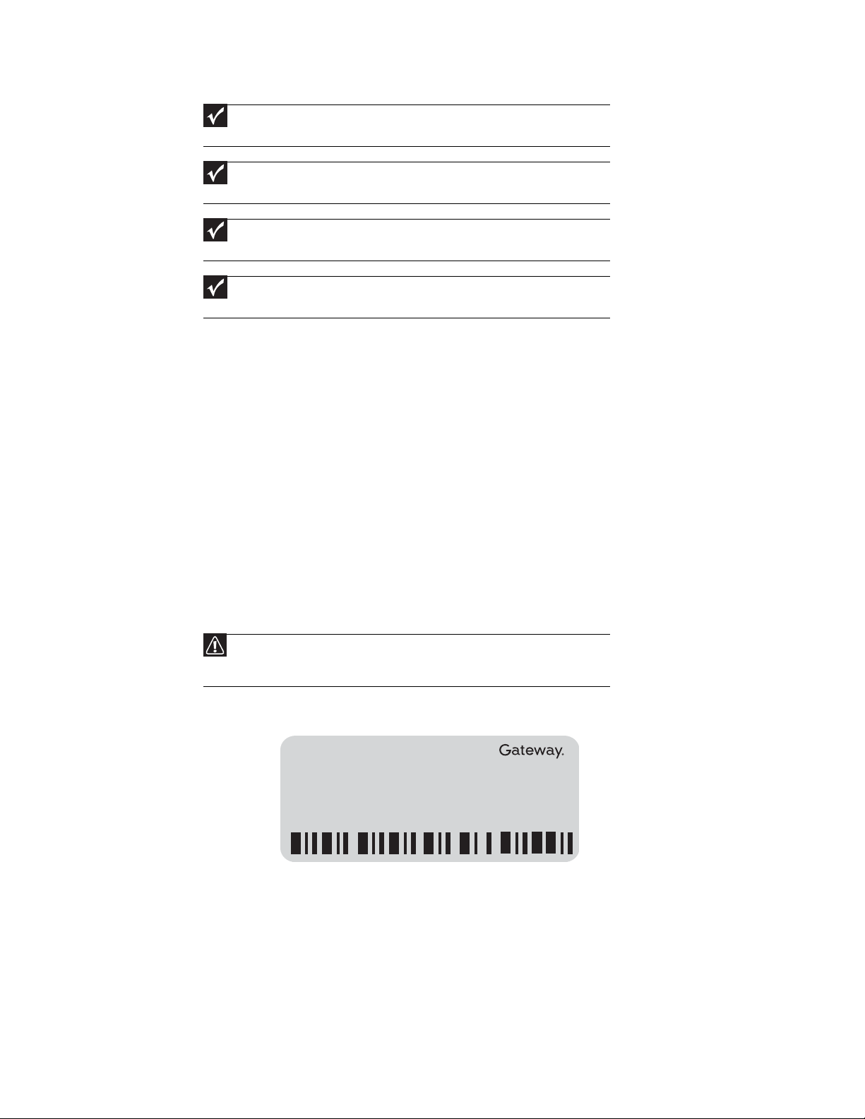
The label on the bottom of the convertible notebook contains information that identifies the
convertible notebook model and its features.
Online Support:
Tech Support Phone:
Hours:
Model:
S/No:
2
www.gateway.com
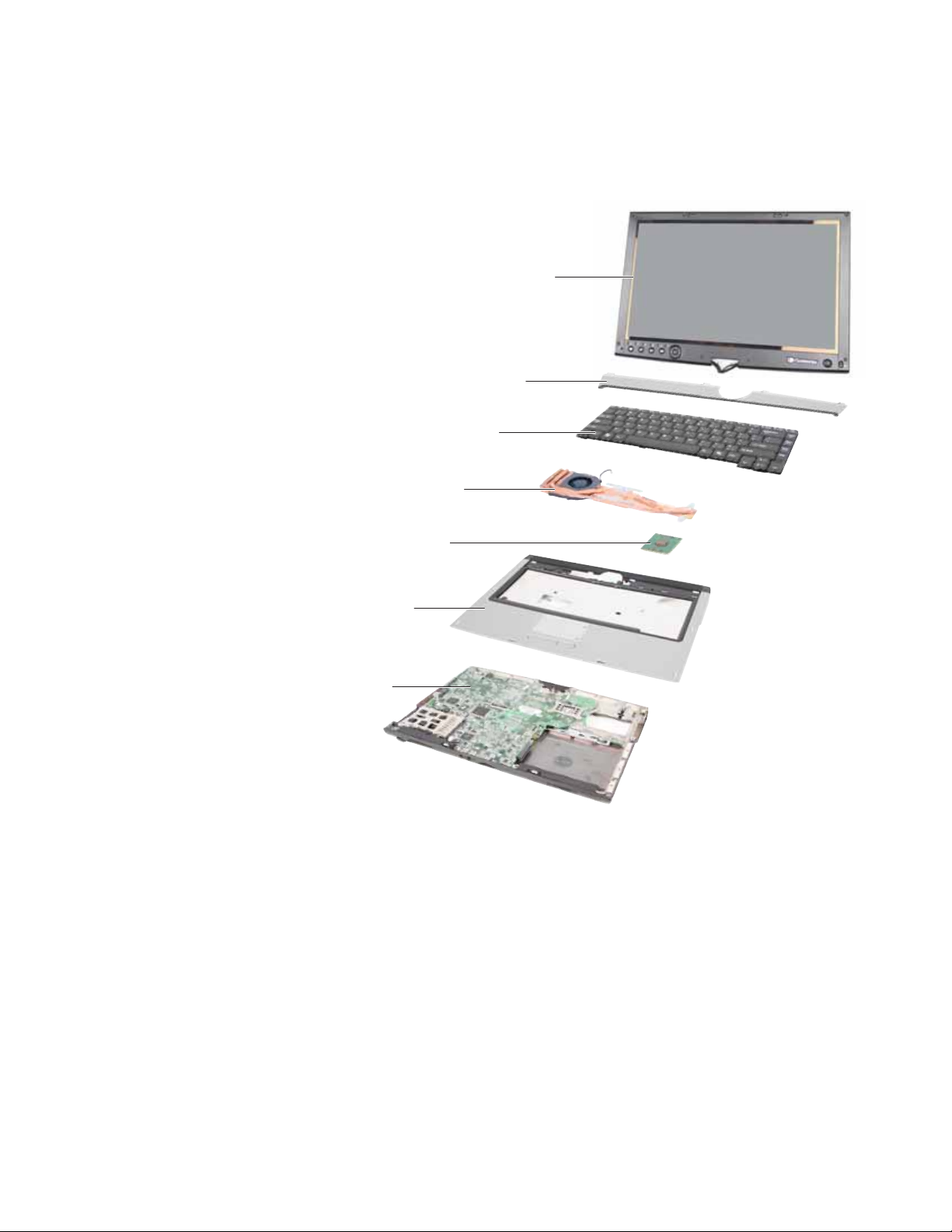
Identifying components
Use this chart to identify the main components of the convertible notebook. For a complete list
of replaceable parts, see “Contents” on pagei.
Key b o a r d c o ve r
(see
Keyboard
page28
(see
Cooling assembly
(see
page11
)
LCD panel assembly
(see
page40
page27
)
)
)
Processor
page14
)
)
Palm res t ass em bly
(see
page50
System board
page58
(see
(see
)
Prepar ing your w ork space
Before perf orming mainten ance on the conv ertible not ebook, mak e sure t hat your w ork space and
the convertible notebook are correctly prepared.
• Wear a grounding (ESD) wrist strap, and use a grounded or dissipative work mat.
• Use a stable and strong table, and make sure that the table top is large enough to hold each
component as you remove it.
• Use bright lighting to make part identification easier.
• Keep your work surface free from clutter and dust that may damage components.
• Use a magn etized screwdriver for removing screws.
3
Replacing convertible notebook components
• When removing components that are attached to the convertible notebook by a cable,
unplug the cable before removing the screws, when possible, to avoid damaging the cable.
• As you remove components and screws, lay them toward the rear of your work surface
(behind the convertible notebook) or far enough to the side that your arms do not
accidentally brush them onto the floor.
• To help keep track of screws, try the following:
• Place each component’s screws in their own section of a parts sorter.
• Place each component’s screws next to the component on your work surface.
• Print the first page of each task, then place the page toward the rear of your work
surface. As you remove screws, place the screws in their respe ctive boxes on the pa ge.
• After loosening screws that are deeply recessed in a hole (for example, on the bottom
of the base assembly), you can leave the screws in the holes if you place small pieces
of masking tape over the hole openings. When reassembling the component, just
remove the tape and tighten the screws.
• When you place flat-headed screws on your work surface, stand them on their heads
to preve nt the screws fro m ro ll ing off th e t ab le.
Pre v enting static electric ity dischar ge
Warning
To avoid exposure to dangerous electrical voltages and moving parts, turn off your
convertible notebook, remove the main and optional secondary batteries, and unplug the
power cord, modem cable, and network cable before opening the case.
Tape
Warning
To prevent risk of electric shock, do not insert any object into the vent holes of the
convertible notebook.
Important
Before performing maintenance on the convertible notebook, you should read and
understand the information in this section.
The components inside your convertible notebook are extr emely sensitive to static electricity, also
known as electrostatic disch arge (ESD ).
Before performing maintenance on the convertible notebook, follow these guideli nes:
• Avoid static-causing surfaces such as carpeted floors, plastic, and packing foam.
• Remove components from their antistatic bags only when you are ready to use them. Do
not lay components on the outside of antistatic bags because only the inside of the bags
provide electrostatic protection.
• Always hold compone nts by their edges. Avoid touching the edge connectors. Never slide
components over any surface.
• Wear a grounding wrist strap (available at most electronics stores) and attach it to a bare
metal part of your workbench or other grounded connection.
• Touch a bare metal surface on your workbench or other grounded object.
Some of the procedures in this guide involve removing tape that holds cables or components. Two
types of tape are used in this Gateway convertible notebook:
• Mylar, non-conductive tape is typically transparent, with a red or brown tint.
• Conductive tape is typically grey or silver.
If the existing tape cannot be reused, replace it with the same type (conductivity) of tape. Both
types of replacement tape should be non-ESD generating tape.
Do not use cellophane tape.
4
www.gateway.com
Preparing t he conv ertible not ebook
To prepare the convertible notebook for maintenance:
1 Make sure that the disc drive is empty.
2 Turn off the convertible notebook.
3 Make sure the LCD panel is in notebook mode, then close the LCD panel.
4 Disconnect your convertible notebook from the optional port replicator.
5 Disconnect the AC adapter, modem cable, and network cable , if connected to the convertible
notebook.
6 Disconnect all peripheral devices connected to the convertible notebook and remove an y PC
Cards and memory cards.
7 Remove the main and optional secondary batteries. For more information, see “Removing
the batteries” on page5.
Removing the batteries
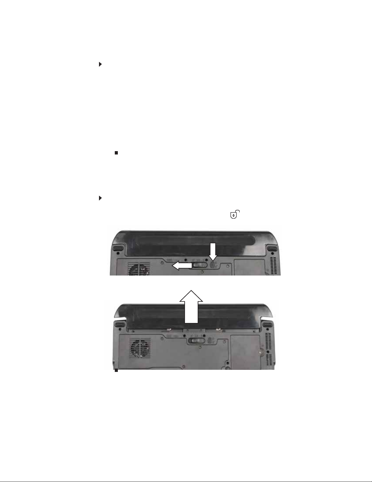
Removing the main battery
To remove th e main battery:
1 Turn the co nver tib le no teb ook ove r so the bo ttom is faci ng up.
2 Slide the battery lock to the unlocked position , then slide the battery release latch.
3 Sli de the ba tter y o ut of t he bay.
5
Replacing convertible notebook components
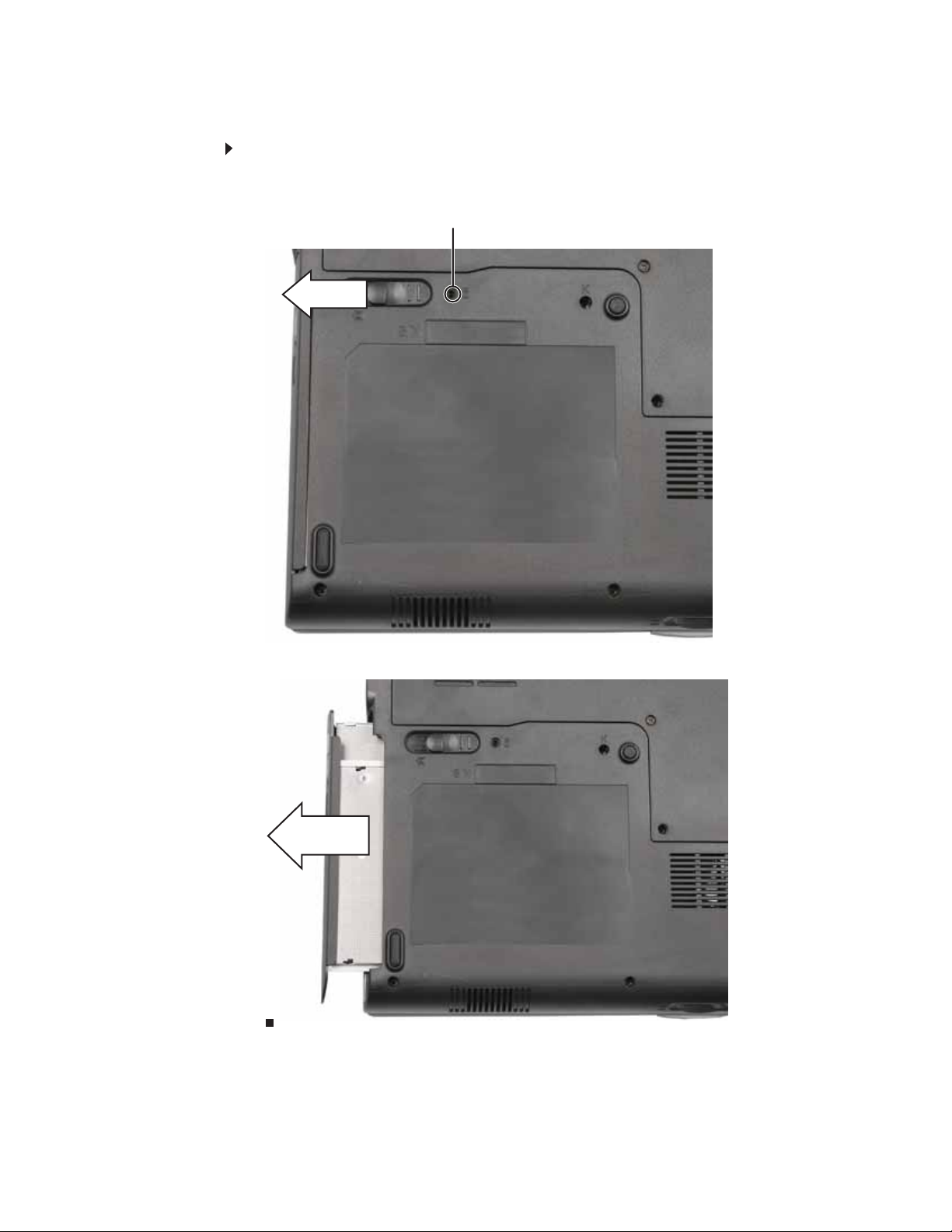
Remo ving the optional secondary battery
To remove the optional secon dary battery:
1 Remove the modular bay lock screw (if one is present), then slide and hold the module bay
latch. Th e ba tter y m ay m ove o ut sl ig htly.
Modular bay lock screw
2 Sli de the ba tter y o ut .
6
www.gateway.com
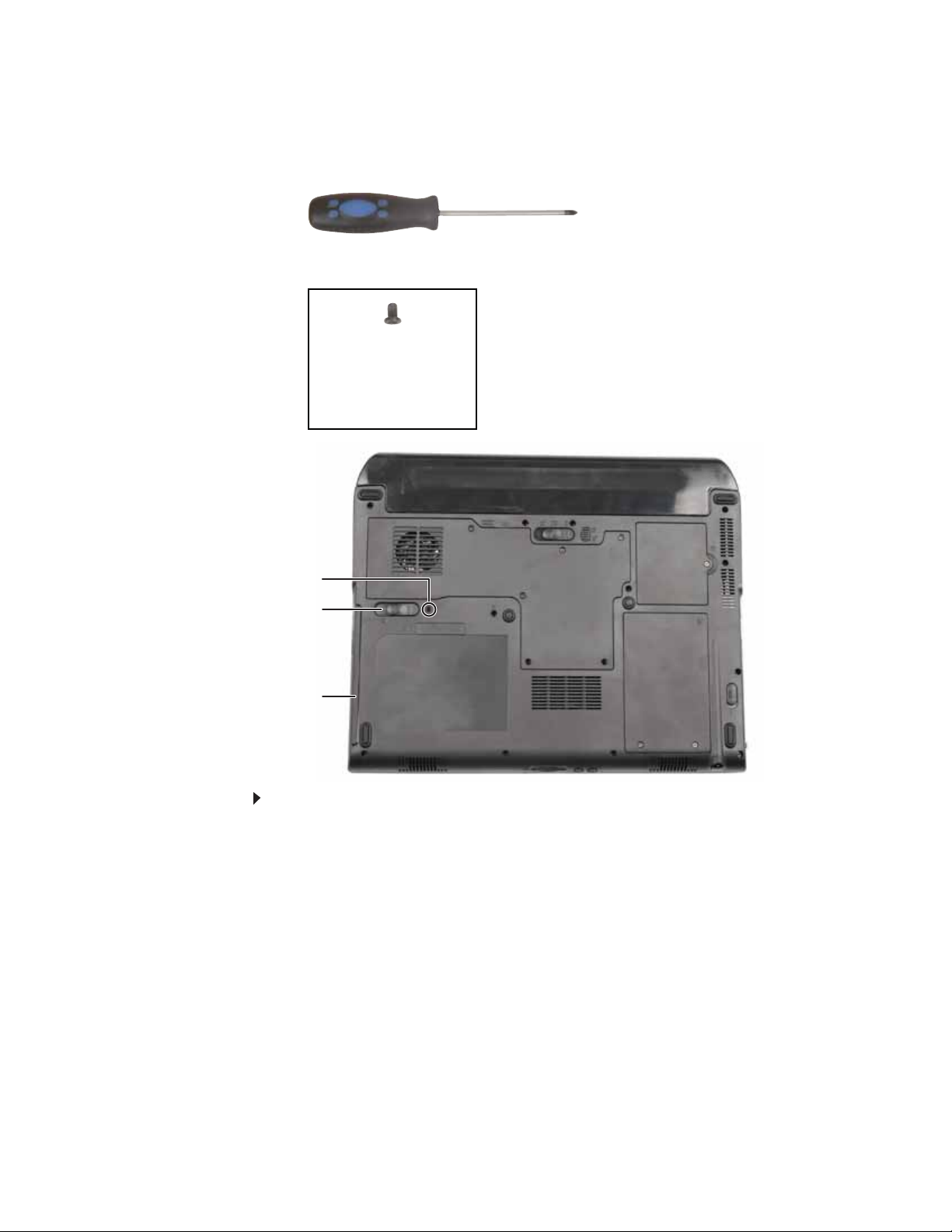
Re placing a ba y module
Tools you need to co mpl ete th is t ask:
Phillips #0 screwdriver
Screws removed during this task:
1 black 2.5*8.0 (Optional
bay module security
screw)
Security screw (optional)
Modula r bay la tch
Modular bay
To replace a bay module:
1 If you are removing a drive, make sure that there is no disc in it.
2 Complete the steps in “Preparing the convertible notebook” on page 5.
3 Turn the co nver tib le no teb ook ove r so the bo ttom is faci ng up.
7
Replacing convertible notebook components
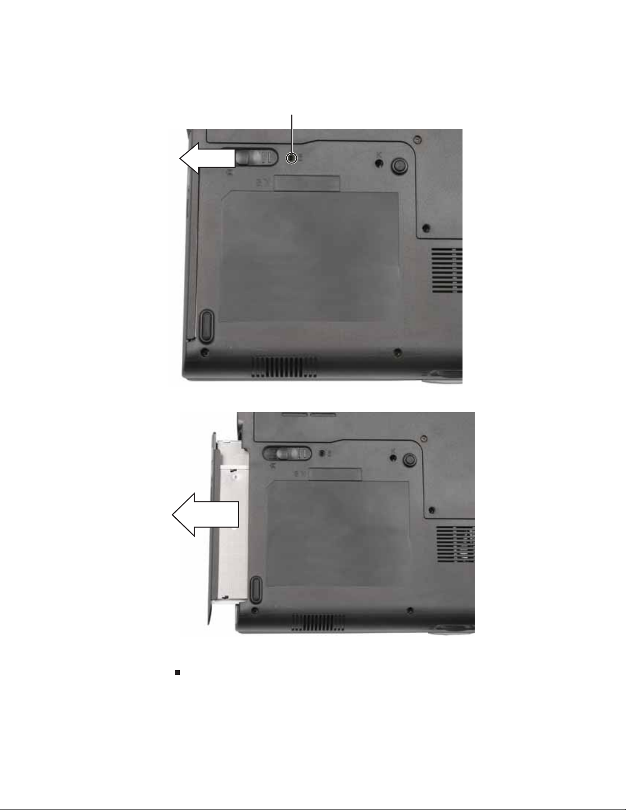
4 Remove the modular bay lock screw (if one is present), then slide and hold the module bay
latch. The drive may move out slightly.
Modular bay lock screw
5 Slide the drive out.
6 Firmly push the new drive straight into the bay until the latch clicks into place.
7 Replace the module bay lock screw.
8
www.gateway.com
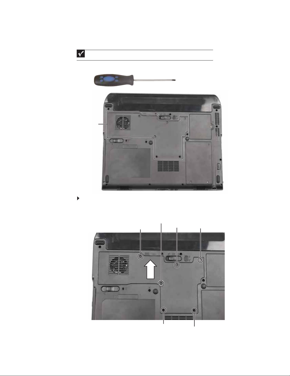
Adding or replac ing memory modules
Important
Use only memory modules designed for this Gateway convertible notebook.
Tools you need to co mpl ete th is t ask:
Phillips #0 screwdriver
Memory bay
To add or replace memory mo dules:
1 Complete the steps in “Preparing the convertible notebook” on page 5.
2 Loosen the screws that secure the memory cover. (These screws cannot be removed.)
Screw
Screw
Screw
Screw
Screw
Screw
3 Remove the memor y bay cover. Be careful not to break off the tabs located on the bottom
of the cover. If the cover does not remove easily, wiggle the cover to loosen it.
9
Replacing convertible notebook components
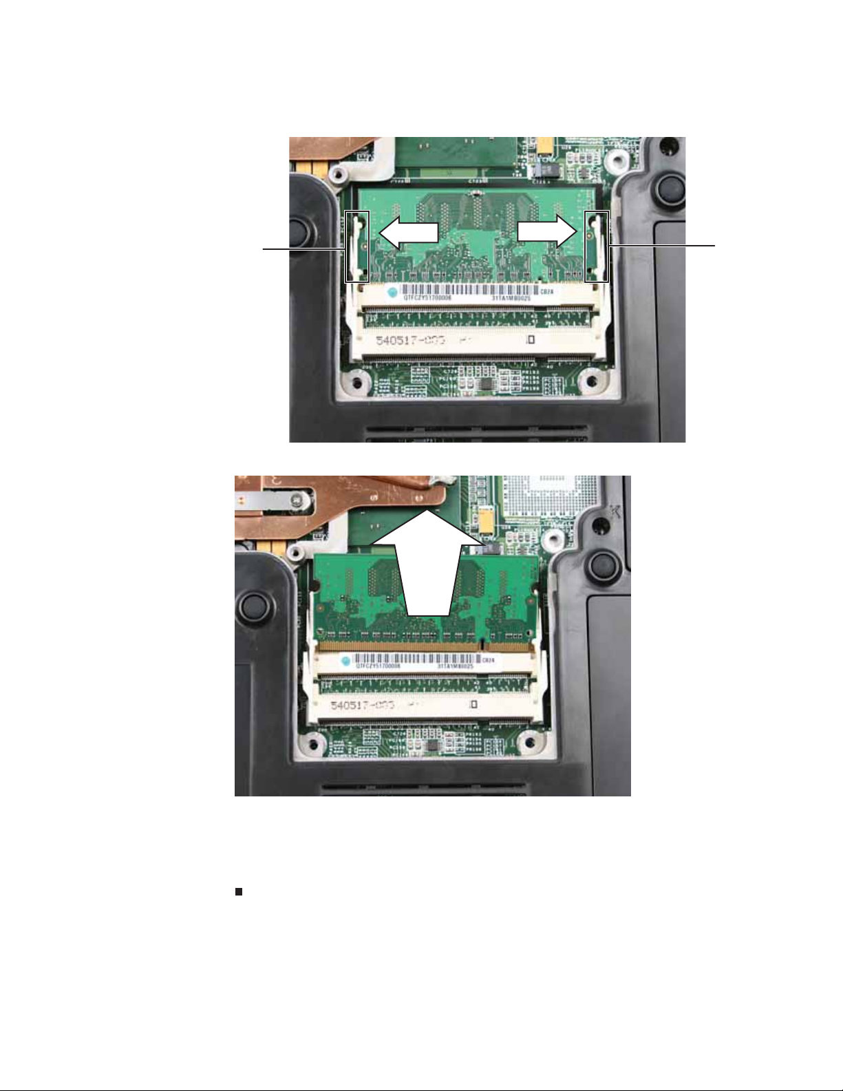
4 If you are removing a memory module, gently press outward on the clip at each end of the
module until the module tilts upward.
Clip
5 Pull the module out of the slot.
Clip
10
6 Hold the new or replacement module at a 30-deg ree angle and press it into the empty
memory slot. This module is keyed so it can only be inserted in one direction. If the module
does not fit, make sure that the notch in the module lines up with the tab in the memory bay.
7 Press the card down until it clicks into place.
8 Replace the memory bay cover, then tighten the cover screws.
www.gateway.com
Re placing the cooling a ssembl y
v
Tools you need to co mpl ete th is t ask:
Phillips #0 screwdriver
Additional materials you need to complete this task:
• X-23-7762 th erm al gre ase
Cooling
assembly
bay
To replace the cooling assembly:
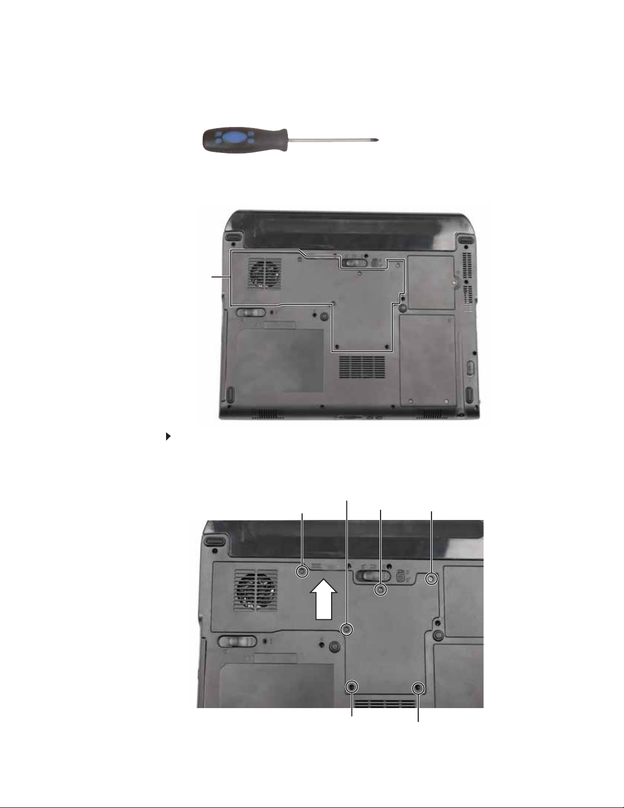
1 Complete the steps in “Preparing the convertible notebook” on page 5.
2 Loosen the screws that secure th e cool ing assemb ly bay cover. (These screws cannot be
removed.)
Screw
Screw
Screw
Screw
Screw
Screw
11
Replacing convertible notebook components
3 Remove the cooli ng assembly bay cover. Be careful not to break off the tabs located on the
botto m o f th e cover. I f th e cover d oes no t re move e asi ly, wig gl e th e c over to l oos en it .
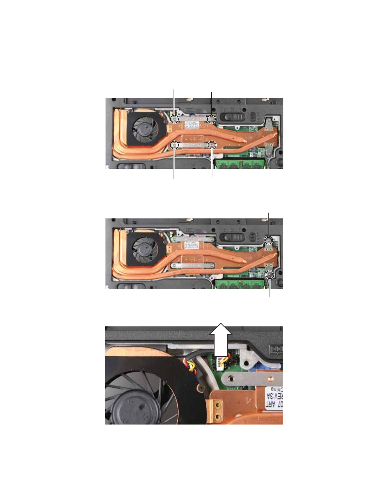
4 Loosen the f our s crews that secure the cooling assembl y t o t he system board. (These scre ws
cannot be removed.) Use the numbers stamped in the metal next to each screw and loosen
the screws in reverse numerical order (start with 4, then 3, then 2, then 1).
Screw Screw
Screw
Screw
5 Loosen the two remaining optional screws that connect the cooling assembly to the system
board. (These screws cannot be removed.)
Screw
Screw
6 Disc on ne ct th e fan from th e sys tem boa rd.
12
www.gateway.com
7 At the same time as you lift, move t he cooling assembly aw ay f rom the side of the conv ertible
notebook.
8 Remove any thermal grease residue from the processor using a soft cloth and isopropyl
alcohol.
9 Place new thermal grease on the processor. Use only enough to cover the CPU die.
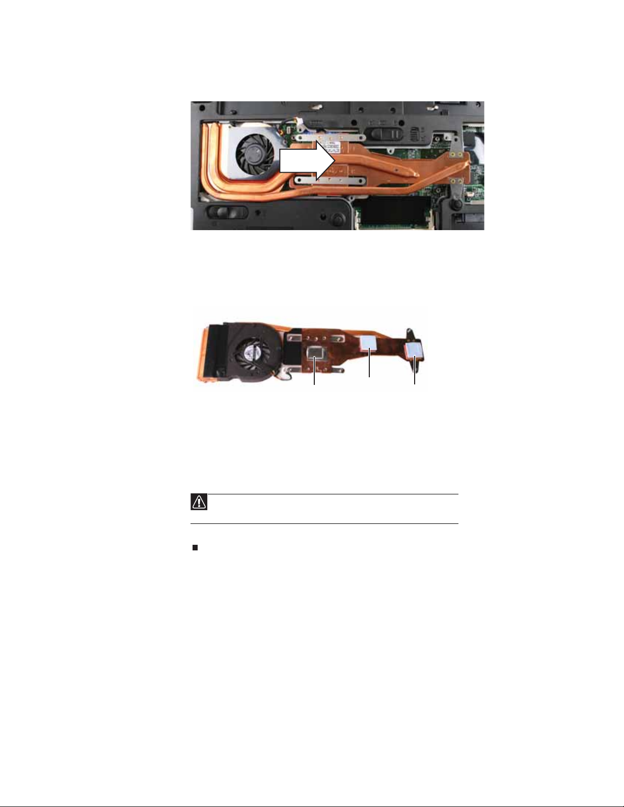
10 Make sure thermal pads are placed between the cooling assembly and other components
as sh own.
Thermal
grease
Thermal
pad
Thermal
pad
11 Insert the new cooling assembly into the convertible notebook.
12 Connect the fan to the system board.
13 Tighten the two optional screws that connect the cooling assembly to the system board.
14 Tighten the four screws that secure the cooling assembly to the system bo ard. Use the
numbers stamped in the metal next t o each sc r ew a nd tighten the s cr e ws in numerical or der
(start with 1, then 2, then 3, then 4 ) .
Caution
When tightening the cooling assembly’s screws into the numbered holes,
tighten them in numerical order.
15 Replace the cooling assembly bay cover, then tighten the cover screws.
13
Replacing convertible notebook components
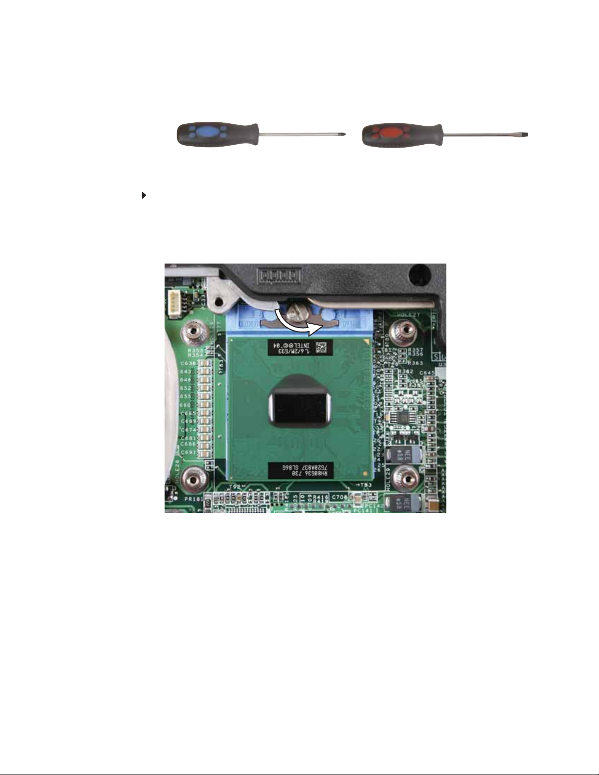
Re placing the pr ocess or
v
Tools you need to co mpl ete th is t ask:
Phillips #0 screwdriver
Additional materials you need to complete this task:
Flat-blade driver
• X-23-7762 th erm al gre ase
To replace the processor:
1 Complete the steps in “Preparing the convertible notebook” on page 5.
2 Remove the cooling assembly by following the steps in “Replacing the cooling assembly” on
page 11.
3 Use a flat-blade screwdriver to turn the p rocessor lo ck screw 1/4- turn co unter-clockwise.
14
www.gateway.com
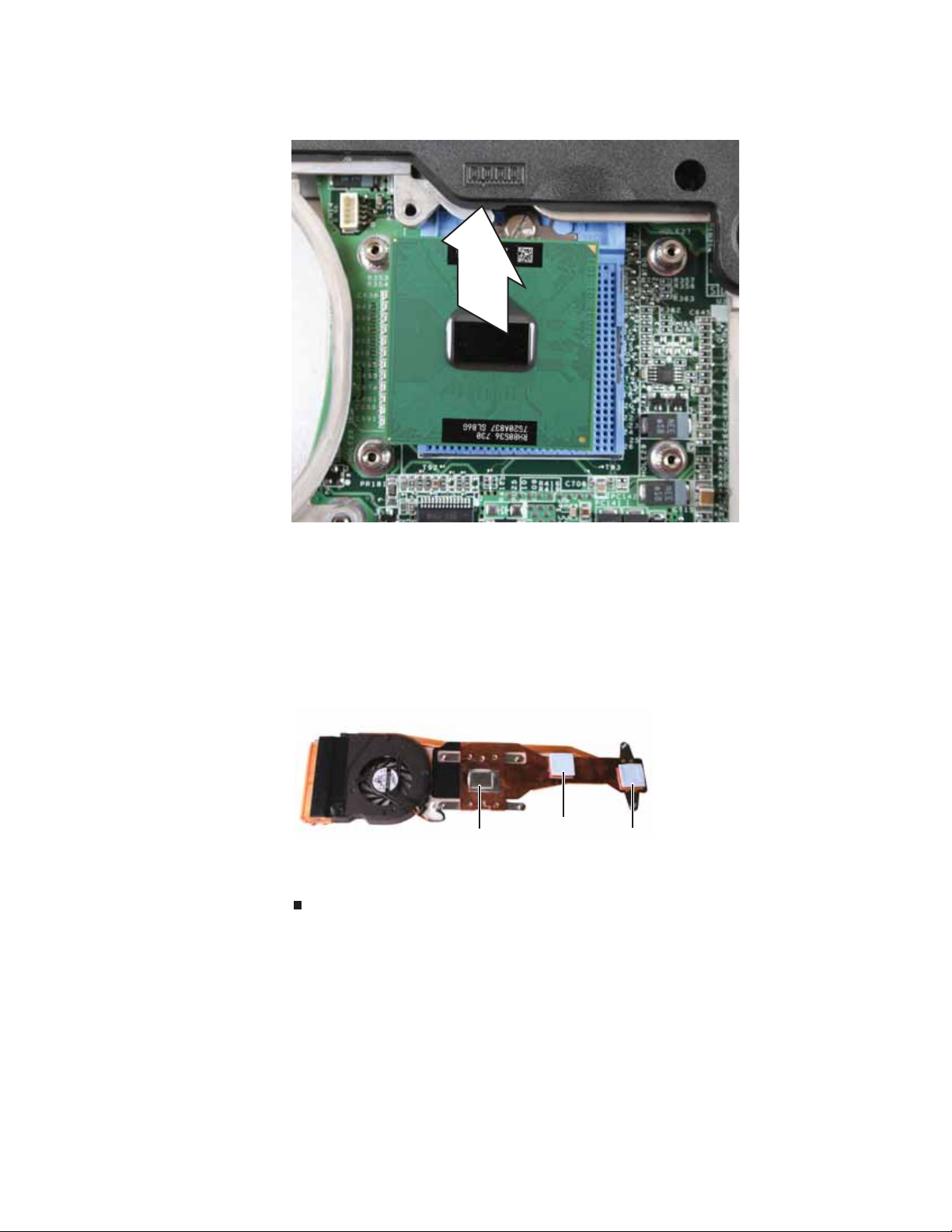
4 Remove the old processor from the system board.
5 Install the new processor onto the system board making sure that Pin 1 on the processor
(indicated by the silk-screened arrow on the corner of the processor) aligns with Pin 1 on
the processor socket (indicated by the absence of a pin hole in the processor socket), then
use a flat-blade screwdriver to turn the processor lock screw 1/4-turn clockwise.
6 Remove any thermal grease residue from the cooling assembly using a soft cloth and
isopropyl alcoh ol.
7 Place new thermal grease on the processor. Use only enough to cover the CPU die.
8 Make sure thermal pads are placed between the cooling assembly and other components
as sh own.
Thermal
grease
Thermal
pad
Thermal
pad
9 Replace the cooling assembly by following the instructions in “Replacing the cooling
assembly” on p age 11.
15
Replacing convertible notebook components
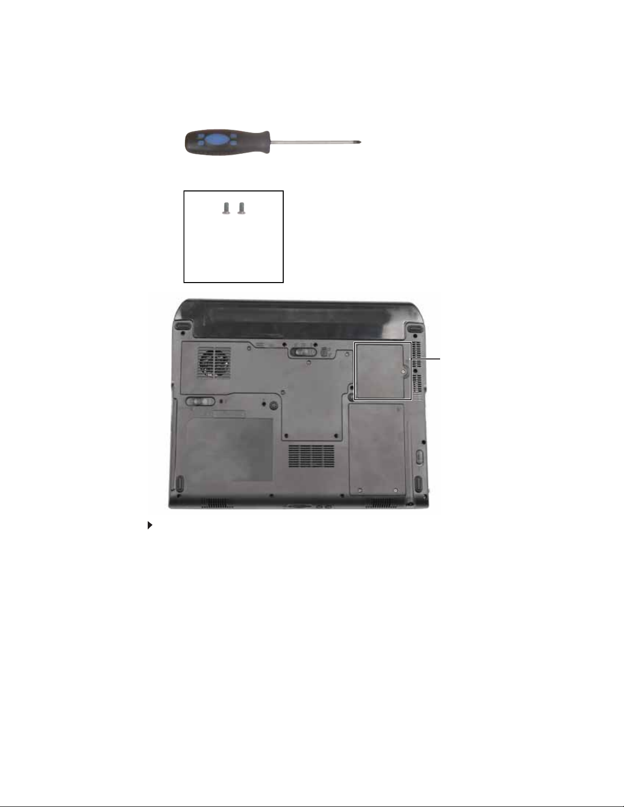
Re placing the IEEE 8 02 . 11 wir eless car d
Tools you need to co mpl ete th is t ask:
Phillips #0 screwdriver
Screws removed during this task:
2 chrome 2.0*3.0
(IEEE 802.11 wireless
card) Select mod els
only
Wirele ss bay
To replace the IEEE 802.11 wireless card:
1 Complete the steps in “Preparing the convertible notebook” on page 5.
16
www.gateway.com
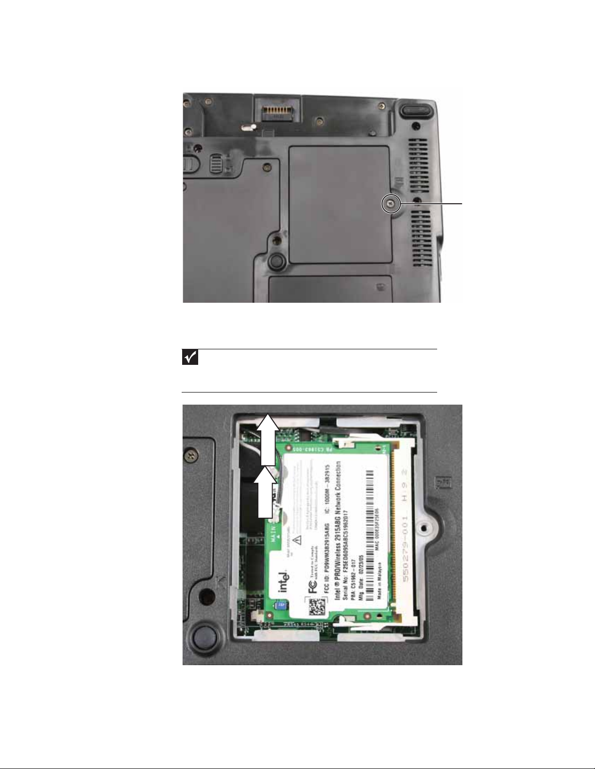
2 Loosen the screw that se cures the wirel ess cover. (This screw cannot be rem oved.)
Screw
3 Remove the wireless bay cover. Be careful not to break off the tabs located on the bottom
of the cover. If the cover does not remove easily, wiggle the cover to loosen it.
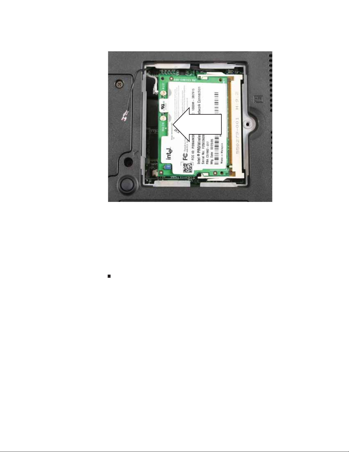
4 Unplug the antenna cables. Note which color cable is connected to each of the connectors.
Important
The number of antenna cables varies by the type of wireless network used
by the convertible notebook. IEEE 802.11N cards typically have three antenna cables.
Other types of wireless network cards typically have two antenna cables. Some
convertible notebook models do not support three antenna cables.
5 Move the antenna cables out of the way.
17
Replacing convertible notebook components
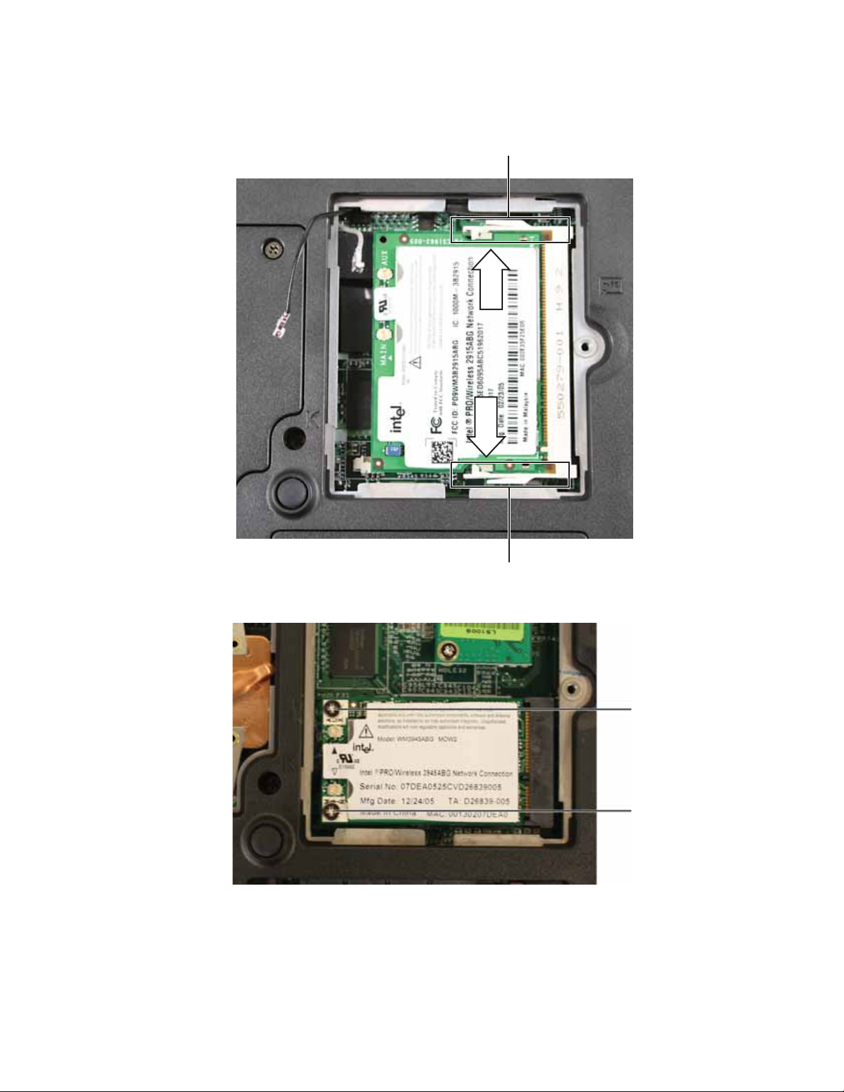
6 If the wireless card is held by clips, press outward on the clip at each side of the card until
0
the card ti lts upward.
Clip
Clip
-ORIf the wireless card is h eld by screws, remove the screws.
Screw
Screw
18
www.gateway.com
7 Pull the card out of the slot.
8 Hold the new card at a 30-degree angle and press it into the empty slot. This card is keyed
so it can only be inserted in one direction. If the card does not fit, make sure that the notch
in the card lines u p with the tab in the card slot.
9 Move the antenna cables out of the way.
10 Press the card down until it clicks into place.
-ORPress the card down, then replac e the screws removed in Step6.
11 Reatt ach the an ten na c abl es to th e c on ne ctors .
12 Replace the wireless bay cover, then tighten the cover screw.
19

Replacing convertible notebook components
Re placing the CMO S batt ery
Important
Use only CMOS batteries designed for this Gateway convertible notebook.
v
Tools you need to co mpl ete th is t ask:
Flat-blade driver Scribe or non-marring tool- OR -
Phillips #0 screwdriver
Screws removed during this task:
2 chrome 2.0*3.0
(IEEE 802.11 wireless
card) Select mod els
only
To replace the CMOS battery:
1 Complete the steps in “Preparing the convertible notebook” on page 5.
2 Open the wireless bay by following the instructions in “Replacing the IEEE 8 02.11 wireless
card” on page16. If your convertible notebook has a wireless card, remove it.
3 Locate the old battery on the system b oard.
20
4 Insert the small flat -blade sc r e wd ri v er or non-marring tool under the old battery and gently
pry it up until it pops out of the socket.
5 Make s u re t he pos it ive (+ ) si de of th e n ew b atte r y i s fa cin g up, th en pr ess t he ba tter y in to
the socket until it snaps into place.
6 If the convertible notebook has wireless networking built in, replace the wireless card by
following the steps in “Replacing the IEEE 802.11 wireless card” on page 16.
7 Replace the wireless bay cover by following the steps in “Replacing the IEEE 802.11 wireless
card” on page16.

www.gateway.com
Re placing the har d driv e
Tools you need to co mpl ete th is t ask:
Phillips #0 screwdriver
Screws removed during this task:
1 chrome 2.5*5.0 (Hard
drive)
4 chrome 3.0*0.5+3.5I
(Hard drive bracket)
Hard
drive
To replace the hard drive:
1 Complete the steps in “Preparing the convertible notebook” on page 5.
21

Replacing convertible notebook components
2 Loosen the screws that secure the hard drive bay cover. (These screws cannot be removed.)
Screw
Screw
3 Remove the hard drive bay cover. Be car eful not to break off the tabs located on the bottom
of the cover. If the cover does not remove easily, wiggle the cover to loosen it.
22

www.gateway.com
4 Remove the hard drive screw.
Screw
23

Replacing convertible notebook components
5 Slide the old hard drive kit out of the convertible notebook.
6 Remove the four screws that secure the hard drive to the hard drive kit bracket.
Screw
Screw
Screw
Screw
7 Insert the new drive into the bracket, label side up, so the screw holes line up.
8 Replace the four screws that were rem oved in Step 6.
24

www.gateway.com
9 Slide the new hard drive into your convertibl e notebook, then replace the screw that was
remove d i n Step4.
10 Replace the hard drive bay cover, then tighten the cover screws.
25

Replacing convertible notebook components
Re placing the hinge co vers
v
Tools you need to co mpl ete th is t ask:
Flat-blade driver Scribe or non-marring tool- OR -
To replace the hinge covers:
1 Complete the steps in “Preparing the convertible notebook” on page 5.
2 Turn the convertible notebook over so the top is facing up.
3 Insert the small flat-blade screwdriver or non-marring tool unde r the bottom of the back
hinge cover, then carefully pry it up.
4 Open the LCD panel to the fully open position, insert the small flat-blade screwdriver or
non-marring tool under the bottom of the front hinge cover, then carefully pry it up.
26
5 Snap the new front cover into place over the hinge, then snap the back cover into place.

www.gateway.com
Re placing the k e yboard co ver
v
Tools you need to co mpl ete th is t ask:
Flat-blade driver Scribe or non-marring tool- OR -
To replace the keyboard cover:
1 Complete the steps in “Preparing the convertible notebook” on page 5.
2 Turn the convertible notebook over so the top is facing up.
3 Open the LCD panel to the fully open position.
4 Insert the small flat-blade scre w dri v er under the bot t om of t he k eyboard cover between the
P
AUSE and INSERT keys and gently pry it up.
5 Insert the small flat-blade scre w dri v er under the bot t om of t he k eyboard cover between the
F1 and F2 keys and gently pry it up.
6 Remove the keyboard cover from the convertible notebook by pulling the co ver toward you
and at the same time lifting its front to clear the keyboard. You will hear small snapping
sounds as the cover comes away from the convertible notebook. Be careful not to break off
the tabs lo cated o n the b ottom of th e cover.
7 Slide the tabs on the bottom side of the new cover under the convertible notebook frame.
8 Press down on the cover in several places to make sure that it is correctly mounted. The
cover is correctly mounted when you can run your finger along the cover and find no loose
spots. The cover should be flat all the way across.
Caution
If the cover is not correctly replaced, the convertible notebook could be
damaged when you try to close the LCD panel.
9 Close the LCD panel.
27

Replacing convertible notebook components
Re placing the k e yboard
v
Tools you need to co mpl ete th is t ask:
Flat-blade driver Scribe or non-marring tool- OR -
Phillips #0 screwdriver
Screws removed during this task:
2 black 2.5*8.0
(Keyboard)
To replace the keyboard:
1 Complete the steps in “Preparing the convertible notebook” on page 5.
2 Remove the two bottom keyboard screws.
Tip
The screw holes are marked with a K.
Screw
Screw
3 Remove the keyboard cover by following the steps in “Replacing the keyboard cover” on
page 27.
28

www.gateway.com
4 Lift the back edge of the k eyboard slightly , then slowly slide it tow ard the L CD panel to release
the keyboard retaining tabs located on the front edge of the keyboard.
5 Care ful ly ro ta te th e keybo ard toward you so i t l ies keys-down on top of yo ur co nvert ibl e
notebook. Be careful not to damage the LCD panel.
6 Swing the black k ey board connector c lip up, then lift the cable out of the connect or . Be careful
not to touch or damage any other components.
Keyboard connector clip
7 Place the new keyboard on your convertible notebook.
8 Make sure the black keyboard conn ector clip is up, insert the cable i nto the connector, then
swing the clip down to lock the connector in place.
Important
The keyboard cable is correctly oriented if it is not twisted.
29

Replacing convertible notebook components
9 Insert the tabs on the front edge of the keyboard into the slots under the palm rest. You
may need to pres s down on the keyboard keys along the front edge of the keyboard to seat
the retaining tabs into their corresponding slots.
10 Gently press the keyboard down until it is flat all the way across. The keyboard should easily
fall into pl ac e. B e c are fu l to no t d am ag e th e LCD pan el .
11 Replace the keyboard cover by following the steps in “Replacing the keyboard cover” on
page 27.
12 Close the LCD panel.
13 Turn your co nver ti ble no teb oo k over so the bo ttom is facin g u p.
14 Replace the screws removed in Step2.
30

Re placing the in ver ter
www.gateway.com
v
Tools you need to co mpl ete th is t ask:
Flat-blade driver Scribe or non-marring tool- OR -
Phillips #0 screwdriver
Screws removed during this task:
4 or 8 black 2.5*5.0 (LCD
panel front)
To replace the inverter:
1 chrome 2.5*2.5
(Inverter)
1 Complete the steps in “Preparing the convertible notebook” on page 5.
2 Remove the keyboard cover by following the steps in “Replacing the keyboard cover” on
page 27.
3 Open the LCD panel to the fully open position.
4 Remove the rubber inserts from the front of the LCD panel assembly.
Important
The number of rubber inserts varies by convertible notebook model.
Insert
InsertInsertInsert
InsertInsertInsertInsert
31

Replacing convertible notebook components
5 Remove the screws from the front of the LCD panel assembly.
Important
The number of screws varies by convertible notebook model.
Screw Screw Screw Screw
Screw Screw Screw
Screw
6 Carefully separate the front and back of the LCD panel assembly.
7 Disc on ne ct th e c onn ecto rs from th e inve rte r.
32
8 Remove the screw that connects the inverter to the front of the LCD panel assembly.
Screw

www.gateway.com
9 Align the new inverter with the screw hole, replace the screw that was removed in Step 8,
then reconnect the cables.
10 Press the LCD panel front and back together. Pres s the two halves together in several places
until they click in place. You should find no loose spots or spots where the two halves do
not meet.
11 Replace the LCD panel assembly screws removed in Step 5.
12 Replace the inserts removed in Step4.
Caution
The larger rubber inserts go across the top of the panel.
13 Replace the keyboard cover by following the steps in “Replacing the keyboard cover” on
page 27.
33

Replacing convertible notebook components
Re placing the po wer but ton board
v
Tools you need to co mpl ete th is t ask:
Flat-blade driver Scribe or non-marring tool- OR -
Phillips #0 screwdriver
Screws removed during this task:
4 or 8 black 2.5*5.0 (LCD
panel front)
To replace the power button board:
2 chrome 2.5*6.0
(Power bu tton
board)
1 Complete the steps in “Preparing the convertible notebook” on page 5.
2 Remove the keyboard cover by following the steps in “Replacing the keyboard cover” on
page 27.
3 Open the LCD panel to the fully open position.
4 Remove the rubber inserts from the front of the LCD panel assembly.
Important
The number of rubber inserts varies by convertible notebook model.
Insert
InsertInsertInsert
InsertInsertInsertInsert
34

www.gateway.com
5 Remove the screws from the front of the LCD panel assembly.
Important
The number of screws varies by convertible notebook model.
Screw Screw Screw Screw
Screw Screw Screw
Screw
6 Carefully separate the front and back of the LCD panel assembly.
7 Disc on ne ct th e p ower butto n cab le from the powe r b utto n b oa rd.
Connector
35

Replacing convertible notebook components
8 Remove th e tw o sc rews th a t c o n n ect th e p owe r bu tto n bo a rd to th e fro nt o f the LCD p a ne l
assembly, then remove the board.
Screw
Screw
9 Install the new power button board.
10 Replace the screws that were removed in Step 8, then reconnect the cable.
11 Press the LCD panel front and back together. Press the two halves together in several places
until they click in place. You should find no l oose spots or spots where the two halves do
not meet.
12 Replace the LCD panel assembly screws removed in Step5.
13 Replace the inserts removed in Step4.
36
Caution
The larger rubber inserts go across the top of the panel.
14 Replace the keyboard cover by following the steps in “Replacing the keyboard cover” on
page 27.

www.gateway.com
Re placing the table t butt on board
v
Tools you need to co mpl ete th is t ask:
Flat-blade driver Scribe or non-marring tool- OR -
Phillips #0 screwdriver
Screws removed during this task:
4 or 8 black 2.5*5.0 (LCD
panel front)
To replace the tablet button board:
2 chrome 2.5*6.0
(T ablet but ton b oard)
1 Complete the steps in “Preparing the convertible notebook” on page 5.
2 Remove the keyboard cover by following the steps in “Replacing the keyboard cover” on
page 27.
3 Open the LCD panel to the fully open position.
4 Remove the rubber inserts from the front of the LCD panel assembly.
Important
The number of rubber inserts varies by convertible notebook model.
Insert
InsertInsertInsert
InsertInsertInsertInsert
37

Replacing convertible notebook components
5 Remove the screws from the front of the LCD panel assembly.
Important
The number of screws varies by convertible notebook model.
Screw Screw Screw Screw
Screw Screw Screw
Screw
6 Carefully separate the front and back of the LCD panel assembly.
7 Disconnect the tablet button cable from the tablet button board.
38
Connector

www.gateway.com
8 Remove the two screws that connect the tablet button board to the front of the LCD panel
assembly, then remove the board.
Screw
Screw
9 Install the new tablet button board.
10 Replace the screws that were removed in Step 8, then reconnect the cable.
11 Press the LCD panel front and back together. Press the two halve s together in several places
until they click in place. You should find no loose spots or spots where the two halves do
not meet.
12 Replace the LCD panel assembly screws removed in Step5.
13 Replace the inserts removed in Step4.
Caution
The larger rubber inserts go across the top of the panel.
14 Replace the keyboard cover by following the steps in “Replacing the keyboard cover” on
page 27.
39

Replacing convertible notebook components
Re placing the L CD a ssembl y
v
Tools you need to co mpl ete th is t ask:
Flat-blade driver Scribe or non-marring tool- OR -
Phillips #0 screwdriver
Screws removed during this task:
4 or 6 black 2.5*8.0 (LCD
hinge to notebook)
To replace the LCD assembly:
1 Complete the steps in “Preparing the convertible notebook” on page 5.
2 If the convertible notebook has wireless networking built in, unplug the wireless antennas
by following the steps in “Replacing the IEEE 802.11 wireless card” on page16.
3 Remove the screws on the bo ttom tha t se cure th e LCD pan el hi nge to the chass is .
Important
The number of screws varies by convertible notebook model.
Screw
Screw
Screw
Screw
4 Turn the convertible notebook over so the top is facing up.
5 Remove the hinge covers by following the steps in “Replacing the hinge covers” on page26.
6 Open the LCD panel to the fully open position.
40
Caution
Be careful not to use too much force when opening the LCD panel.

www.gateway.com
7 Remove the keyboard cover by following the steps in “Replacing the keyboard cover” on
page 27.
8 Detach the three c ables from the system b oard.
9 Grasp the plastic tab carefully and pull to unplug the LCD video cable from the convertible
notebook. Make sure you grasp the tab, not the cable.
Caution
The connector is fragile.
10 Taki ng car e to note th e c abl es’ rou ti ng an d p osi ti ons as they a re i ns ta ll ed from Ga teway,
pull the antenna cables out from under the syst em board, then slide the wi res out f rom under
the retaining clips.
11 Remove the two screws on the top that se cure the LCD pa nel h inge to the chassis.
Screw
Screw
41

Replacing convertible notebook components
12 Li ft th e LCD p ane l ass emb ly u p a nd away fro m th e c onve rti bl e no teb oo k. The LCD pa ne l
assemb ly is now c om plete ly det ach ed from the conve rtib le noteb ook .
13 Place the new LCD panel assembly onto the con vertible notebook, then replace the two hinge
screws removed in Step 11.
14 Slide the antenna cables through the retaining clips, under the system board, then into the
wireless card a rea.
15 Plug the LCD video cable into the convertible notebook.
16 Reattach the three cables to the appropriate connectors on the system board.
17 Replace any tape that held the antenna wires and LCD cable.
18 Replace the keyboard cover by following the steps in “Replacing the keyboard cover” on
page 27.
19 Replace the hinge covers by following the steps in “Replacing the hinge covers” on page26.
20 Turn th e co nve rtib l e no teb oo k ove r s o th e b ottom is faci ng up .
21 Replace the hinge screws removed in Step 3.
22 Rec onn ect th e an ten na w ires to th e w ire less ca rd by foll owin g t he step s i n “Replacing the
IEEE 802.11 wireless card” on page16.
23 Replace the wireless bay cover by following the steps in “Replacing the IEEE 802.11 wireless
card” on page16.
42

www.gateway.com
Re placing the L CD panel hinge
v
Tools you need to co mpl ete th is t ask:
Flat-blade driver Scribe or non-marring tool- OR -
Phillips #0 screwdriver
Screws removed during this task:
4 or 6 black 2.5*8.0 (LCD
hinge to notebook)
To replace the LCD panel hinge:
4 or 8 black 2.5*5.0 (LCD
panel front)
4 black 2.5*3.5 (LCD
hinge to LCD panel)
1 Complete the steps in “Preparing the convertible notebook” on page 5.
2 If the convertible notebook has wireless networking built in, unplug the wireless antennas
by following the steps in “Replacing the IEEE 802.11 wireless card” on page16.
3 Remove the hinge covers by following the steps in “Replacing the hinge covers” on page26.
4 Remove the keyboard cover by following the steps in “Replacing the keyboard cover” on
page 27.
5 Remove t he LCD as sembly b y follow ing the step s in “Replacing the LCD as sembly” on page 40.
6 Open the LCD panel to the fully open position.
7 Remove the rubber inserts from the front of the LCD panel assembly.
Important
The number of rubber inserts varies by convertible notebook model.
Insert
InsertInsertInsert
InsertInsertInsertInsert
43

Replacing convertible notebook components
8 Remove the screws from the front of the LCD panel assembly.
Important
The number of screws varies by convertible notebook model.
Screw Screw Screw Screw
Screw Screw Screw
Screw
9 Carefully separate the front and back of the LCD panel assembly.
10 Carefully pull the wiring out of the hinge.
Tip
Start by pulling the wire that ha s the smallest connect or out of the hinge. Then
proceed to the wire that has the next biggest connector and so on.
44

www.gateway.com
11 Remove the four screws that secure the old hinge to the LCD panel assembly.
Screws
Screws
12 Replace the new hinge onto the LCD panel assembly.
13 Replace the screws removed in Step11.
14 Feed the wiring back into the hinge.
Tip
Star t by feed in g the w ire tha t h as th e la rge s t c on n e ctor in to the h in g e. The n
proceed to the wire that has the next smallest connector and so on.
15 Replace the screws that were removed in Step 8, then reconnect the cable.
16 Press the LCD panel front and back toge ther. Press the two halves together in se veral places
until they click in place. You should find no loose spots or spots where the two halves do
not meet.
17 Replace the LCD panel assembly screws removed in Step 5.
18 Replace the inserts removed in Step4.
Caution
The larger rubber inserts go across the top of the panel.
19 Replace the LCD assembly by following the step s in “Replac ing the LCD assembly” on page40.
20 Replace the keyboard cover by following the steps in “Replacing the keyboard cover ” on
page 27.
21 Replace the hinge covers by following the steps in “Replacing the hinge covers” on page26.
22 Rec onn ect th e an ten na w ires to th e w ire less ca rd by foll owin g t he step s i n “Replacing the
IEEE 802.11 wireless card” on page16.
23 Replace the wireless bay cover by following the steps in “Replacing the IEEE 802.11 wireless
card” on page16.
45

Replacing convertible notebook components
Re placing the L CD panel
v
Tools you need to co mpl ete th is t ask:
Flat-blade driver Scribe or non-marring tool- OR -
Phillips #0 screwdriver
Screws removed during this task:
4 or 6 black 2.5*8.0 (LCD
hinge to notebook)
To replace the LCD panel:
4 or 8 black 2.5*5.0 (LCD
panel front)
4 black 2.5*8.0 (LCD
panel)
1 Complete the steps in “Preparing the convertible notebook” on page 5.
2 If the convertible notebook has wireless networking built in, unplug the wireless antennas
by following the steps in “Replacing the IEEE 802.11 wireless card” on page16.
3 Remove the hinge covers by following the steps in “Replacing the hinge covers” on page26.
4 Remove the keyboard cover by following the steps in “Replacing the keyboard cover” on
page 27.
5 Remove t he LCD as sembly b y follow ing the step s in “Replacing the LCD ass embly” on page 40.
6 Disconnect the right inverter connector by following the instructions in “Repl acing the
inverter” on page 31.
7 Disconnect the tablet button board by following the instructions in “Replacing the tablet
button board” on page37.
8 Carefully pull the wiring out of the hinge.
46
Tip
Start by pulling the wire that ha s the smallest connect or out of the hinge. Then
proceed to the wire that has the next biggest connector and so on.

www.gateway.com
9 Remove the screws connecting the LCD panel to the LCD lid.
Screw
Screw
Screw
Screw
10 Remove the old LCD panel from the LCD lid.
11 Place the new LCD panel into the LCD lid.
12 Replace the screws removed in Step9.
13 Feed the wiring back into the hinge.
Tip
Star t by feed in g the w ire tha t h as th e la rge s t c on n e ctor in to the h in g e. The n
proceed to the wire that has the next smallest connector and so on.
14 Reconnect the tablet button board by following the instructions in “Replacing the tablet
button board” on page37.
15 Reconnect the inverter and reassemble the LCD assembly by following the instructions in
“Replacing the inverter ” on page 31.
16 Replace the LCD assembly by following the step s in “Replac ing the LCD assembly” on page40.
17 Replace the keyboard cover by following the steps in “Replacing the keyboard cover” on
page 27.
18 Replace the hinge covers by following the steps i n “Replacing the hinge covers” on page 26.
19 Re co nn ect the ante nn a wi res to the wi rel ess car d by fo llo win g th e s teps in “Replacing the
IEEE 802.11 wireless card” on page16.
20 Replace the wireless bay cover by following the steps in “Replacing the IEEE 802.11 wireless
card” on page16.
47

Replacing convertible notebook components
Re placing the L CD a ssembl y lid
v
Tools you need to co mpl ete th is t ask:
Flat-blade driver Scribe or non-marring tool- OR -
Phillips #0 screwdriver
Screws removed during this task:
4 or 6 black 2.5*8.0 (LCD
hinge to notebook)
2 chrome 2.5*6.0
(Power butto n
board)
4 or 8 black 2.5*5.0 (LCD
panel front)
2 chrome 2.5*6.0
(T ablet but ton b oard)
1 chrome 2.5*2.5
(Inverter)
4 black 2.5*3.5 (LCD
hinge to LCD panel)
48
4 black 2.5*8.0 (LCD
panel)
To replace the LCD assembly lid:
1 Complete the steps in “Preparing the convertible notebook” on page 5.
2 If the convertible notebook has wireless networking built in, unplug the wireless antennas
by following the steps in “Replacing the IEEE 802.11 wireless card” on page16.
3 Remove the hinge covers by following the steps in “Replacing the hinge covers” on page26.
4 Remove the keyboard cover by following the steps in “Replacing the keyboard cover” on
page 27.
5 Remove t he LCD as sembly b y follow ing the step s in “Replacing the LCD ass embly” on page 40.
6 Remove the inverter by following the instructions in “Replacing the inverter ” on page 31.
7 Remov e the power bu tton boar d by fo llowing th e instructions i n “Replacing the power butt on
board” on page 34.
8 Remov e th e tablet b utt on boar d b y f ol low ing t he instr uc tions in “R eplac ing the tablet button
board” on page 37.

www.gateway.com
9 Remov e the L CD panel hinge b y fol low ing the instruc tions in “R eplacing t he L CD panel hinge”
on page 43.
10 Remove the screws connecting the LCD panel to the old LCD lid.
Screw
Screw
Screw
Screw
11 Remove the LCD panel from the old LCD lid.
12 Place the LCD panel into the new LCD lid.
13 Replace the screws removed in Step10.
14 Replace the L C D panel hinge by followi ng the instructions in “Replac ing the L CD panel hinge”
on page 43.
15 Replace the tablet b ut t on b oar d by following th e instr uc tion s in “Replac ing the tablet butt on
board” on page 37.
16 Replace the power button board b y follo wing the instruc tions in “Replacing the powe r button
board” on page 34.
17 Replace the inverter and reassemble the LCD assembly by following the instructions in
“Replacing the inverter ” on page 31.
18 Replace the LCD assembly by follow ing the steps in “Replac ing t he L CD as sembly” on page40.
19 Replace the keyboard cover by following the steps in “Replacing the keyboard cover” on
page 27.
20 Replace the hinge covers by following the steps in “Replacing the hinge covers” on page26.
21 Re co nn ect the ante nn a wi res to the wi rel ess car d by fo llo win g th e s teps in “Replacing the
IEEE 802.11 wireless card” on page16.
22 Replace the wireless bay cover by following the steps in “Replacing the IEEE 802.11 wireless
card” on page16.
49

Replacing convertible notebook components
Re placing the palm r est
v
Tools you need to co mpl ete th is t ask:
Flat-blade driver Scribe or non-marring tool- OR -
Phillips #0 screwdriver
Screws removed during this task:
1 black 2.5*8.0 (Optional
bay module security
screw)
4 or 6 black 2.5*8.0 (LCD
hinge to notebook)
1 chrome 2.5*5.0 (Hard
drive)
14-16 black 2.5*8.0
(palm rest-bottom)
2 black 2.5*8.0
(Keyboard)
2 chrome 2.0*5.0
(palm rest-hard drive
bay)
50
3 chrome 2.0-0.4*2.0
(palm rest-modular
drive bay)
To replace the palm rest:
1 black 2.5*8.0 (palm
rest-top)
2 chrome 2.0*3.0
(Fingerpri nt read er)
1 Complete the steps in “Preparing the convertible notebook” on page 5.
2 Remove the bay module by following the steps in “Replacing a bay module” on page 7.
3 If the convertible notebook has wireless networking built in, unplug the wireless antennas
by following the steps in “Replacing the IEEE 802.11 wireless card” on page16.
4 Remove the hard drive by following the steps in “Replacing the hard drive” on page 21.
5 Remove the hinge covers by following the steps in “Replacing the hinge covers” on page26.
6 Remove the keyboard cover by following the steps in “Replacing the keyboard cover” on
page 27.
7 Remove the keyboard by following the steps in “Replacing the keyboard” on page 28.
8 Remove t he LCD as sembly b y follow ing the step s in “Replacing the LCD ass embly” on page 40.

www.gateway.com
9 Remove the screws shown in the following picture. Note the location of the sc rew types and
sizes. Some models may have fewer screws than shown or screws in a slightly different
location.
Important
The number of screws varies by convertible notebook model.
Screws
Screws
Screws
Screws
10 Turn the convertible notebook over so the top is facing up.
11 Flip the black touchpad connector clip up, then remove the cable. Be careful not to touch or
damage any other components.
Fingerprint reader connector
Touc hpad connec t or
12 Disconnect the optional fingerprint reader from the system board.
51

Replacing convertible notebook components
13 Re move the scr ew fro m th e top o f the pal m r est .
Screw
14 Starting on the right side, lift the palm rest assembly up and away from the convertible
notebook. Be careful when pulling the palm rest assembly away from the bottom near the
docking port.
15 Turn the palm rest over so the bottom is facing up, then remove the optional fingerprint
reader fr om the ol d palm re st and instal l it on t he new palm res t by f ol lowin g the instr ucti ons
in “Replacing the fingerprint reader” on page 53.
16 Place the new palm rest assembly onto the convertible notebook, then snap the assembly
into place.
17 Replace the screw removed in Step 13.
18 Connect the fingerprint reader to the system board.
19 Make sure the black touchpad connector clip is in the raised position, insert the cable into
the connector, then lower the black connector clip to lock the cable in place.
20 Turn th e co nve rtib l e no teb oo k ove r s o th e b ottom is faci ng up .
21 Replace the screws removed in Step9.
22 Replace the LCD assembly b y follo wing the steps in “R eplaci ng the L CD a ssembl y” on page40.
23 Replace the keyboard by following the steps in “Replacing the keyboard” on page 28.
24 Replace the keyboard cover by following the steps in “Replacing the keyboard cover” on
page 27.
25 Replace the hinge covers by following the steps in “Replacing the hinge covers” on page 26.
26 Replace the hard drive by following the steps in “Replacing the hard drive” on page 21.
27 If the convertible notebook has wir eless netw orking built in, plug the wireles s antennas back
in by following the steps in “Replacing the IEEE 802.11 wireless card” on page 16.
28 Replace the wireless bay cover by following the steps in “Replacing the IEEE 802.11 wireless
card” on page16.
29 Insert the bay mo du le by followin g th e i ns tru ction s in “Replacing a bay module” on page 7.
52

www.gateway.com
Re placing the finger print reader
v
Tools you need to co mpl ete th is t ask:
Flat-blade driver Scribe or non-marring tool- OR -
Phillips #0 screwdriver
Screws removed during this task:
1 black 2.5*8.0 (Optional
bay module security
screw)
4 or 6 black 2.5*8.0 (LCD
hinge to notebook)
1 chrome 2.5*5.0 (Hard
drive)
14-16 black 2.5*8.0
(palm rest-bottom)
2 black 2.5*8.0
(Keyboard)
2 chrome 2.0*5.0
(palm rest-hard drive
bay)
3 chrome 2.0-0.4*2.0
(palm rest-modular
drive bay)
To replace the fingerprint reader:
1 black 2.5*8.0 (palm
rest-top)
2 chrome 2.0*3.0
(Fingerpri nt read er)
1 Complete the steps in “Preparing the convertible notebook” on page 5.
2 Remove the bay module by following the steps in “Replacing a bay module” on page 7.
3 If the convertible notebook has wireless networking built in, unplug the wireless antennas
by following the steps in “Replacing the IEEE 802.11 wireless card” on page16.
4 Remove the hard drive by following the steps in “Replacing the hard drive” on page 21.
5 Remove the keyboard cover by following the steps in “Replacing the keyboard cover” on
page 27.
6 Remove the keyboard by following the steps in “Replacing the keyboard” on page28.
7 Remove t he LCD as sembly b y follow ing the step s in “Replacing the LCD as sembly” on page 40.
8 Remove the palm rest by following the steps in “Replacing the palm rest” on page 50.
9 Turn the palm rest over so the back side is facing up.
53

Replacing convertible notebook components
10 Disconnect the fingerprint reader cable.
11 Remove the screws from the metal clips covering the ends of the fingerprint reader.
Screw
Screw
12 Lift the metal clips off of the fingerprint reader.
Clip
Clip
13 Remove the fingerprint reader from the convertible notebook.
14 Place the new fing erprint reader into the convertible notebook in the same orientation as
the old reader.
15 Lay the clips on the fingerprint reader, then replace the screws removed in Step 11.
16 Plug the fingerprint reader cable i nto the fingerprint reader.
54

www.gateway.com
17 Replace the palm rest by following the steps in “Replacing the palm rest” on page 50.
18 Replace the LCD assembly by follow ing the steps in “Replac ing t he L CD as sembly” on page40.
19 Replace the keyboard by following the steps in “Replacing the keyboard” on page28.
20 Replace the keyboard cover by following the steps in “Replacing the keyboard cover ” on
page 27.
21 Replace the hinge covers by following the steps in “Replacing the hinge covers” on page26.
22 Replace the hard drive by following the steps in “Replacing the hard drive” on page 21.
23 If the conver tible not ebook ha s wir eless netw orking built in, p lug the w irele ss ant enna s bac k
in by following the steps in “Replacing the IEEE 802.11 wireless card” on page 16.
24 Replace the wireless bay cover by following the steps in “Replacing the IEEE 802.11 wireless
card” on page16.
25 Insert the bay mo du le by followin g th e i ns tru ction s in “Replacing a bay module” on page 7.
55

Replacing convertible notebook components
Re placing the Blue tooth module
v
Tools you need to co mpl ete th is t ask:
Flat-blade driver Scribe or non-marring tool- OR -
Phillips #0 screwdriver
Screws removed during this task:
1 black 2.5*8.0 (Optional
bay module security
screw)
4 or 6 black 2.5*8.0 (LCD
hinge to notebook)
1 chrome 2.5*5.0 (Hard
drive)
14-16 black 2.5*8.0
(palm rest-bottom)
2 black 2.5*8.0
(Keyboard)
2 chrome 2.0*5.0
(palm rest-hard drive
bay)
56
3 chrome 2.0-0.4*2.0
(palm rest-modular
drive bay)
To replace the Bluetooth module:
1 black 2.5*8.0 (palm
rest-top)
1 Complete the steps in “Preparing the convertible notebook” on page 5.
2 Remove the bay module by following the steps in “Replacing a bay module” on page 7.
3 If the convertible notebook has wireless networking built in, unplug the wireless antennas
by following the steps in “Replacing the IEEE 802.11 wireless card” on page16.
4 Remove the hard drive by following the steps in “Replacing the hard drive” on page 21.
5 Remove the hinge covers by following the steps in “Replacing the hinge covers” on page26.
6 Remove the keyboard cover by following the steps in “Replacing the keyboard cover” on
page 27.
7 Remove the keyboard by following the steps in “Replacing the keyboard” on page 28.
8 Remove t he LCD as sembly b y follow ing the step s in “Replacing the LCD ass embly” on page 40.
9 Remove the palm rest by following the steps in “Replacing the palm rest” on page 50.

www.gateway.com
10 Disconnect the cable from the old Bluetooth module, then slide the module from the
convertible notebook.
11 Slide the new Bluetooth module into the convertibl e notebook.
12 Connect the cable to the new Bluetooth module.
13 Replace the palm rest by following the steps in “Replacing the palm rest” on page50.
14 Replace the L CD assembl y by f ollowing the steps in “Rep lacing t he L CD as sembly” on page40.
15 Replace the keyboard by following the steps in “Replacing the keyboard” on page28.
16 Replace the keyboard cover by following the steps in “Replacing the keyboard cover” on
page 27.
17 Replace the hinge covers by following the steps in “Replacing the hinge covers” on page 26.
18 Replace the hard drive by following the steps in “Replacing the hard drive” on page 21.
19 If the convertible not ebook ha s wir eles s netw orking buil t in, plug the w irele ss an tenn as bac k
in by following the steps in “Replacing the IEEE 802.11 wireless card” on page 16.
20 Replace the wireless bay cover by following the steps in “Replacing the IEEE 802.11 wireless
card” on page16.
21 In se rt th e bay mo du le by following th e in st ructio n s in “Replacing a bay module” on page 7.
57

Replacing convertible notebook components
Re placing the s yst em board
v
Tools you need to co mpl ete th is t ask:
Flat-blade driver Scribe or non-marring tool- OR -
Phillips #0 screwdriver
Additional materials you need to complete this task:
5.0 m m hex nutdr iver
• X-23-7762 th erm al gre ase
Screws removed during this task:
1 black 2.5*8.0 (Optional
bay module security
screw)
2 chrome 2.0*3.0
(IEEE 802.11 wireless
card) Select models
only
2 black 2.0*2.5 (TPM
module)
1 chrome 2.5*5.0 (Hard
drive)
14-16 black 2.5*8.0
(palm rest-bottom)
1 black 2.5*8.0 (palm
rest-top)
To replace the system board:
2 black 2.5*8.0
(Keyboard)
2 chrome 2.0*5.0
(palm rest-hard drive
bay)
2-4 black 2.5*5.0 (System
board)
4 or 6 black 2.5*8.0 (LCD
hinge to notebook)
3 chrome 2.0-0.4*2.0
(palm rest-modular
drive bay)
2 chrome 2.0*2.5
(modem)
1 Complete the steps in “Preparing the convertible notebook” on page 5.
2 Remov e the ba y module b y f ollow ing the in struc tions in “R eplacing a bay module” on page7.
3 Remove the memory from the old system board and install it on the new system board by
following the instructions in “Adding or replacing memory modules” on page 9.
58

www.gateway.com
4 Remove the cooling assembly by following the instructions in “Replacing the cooling
assembly” on p age 11.
5 If your new system board does not include a processor, remove the processor from the old
system board and ins tall it on the new system board by following the i nstruction s in
“Replacing the processor” on page 14.
6 Remove the optional IEEE 802.11 wireless card from the old system board and install it on
the new system board by following the instructions in “Replacing the IEEE 802.11 wireless
card” on page16.
7 If the optional TPM module is located in the wireless bay, remove it from the old system
board and install it on the n ew system board by following the instructions in “Replacing the
TPM module (select models)” on page 66.
8 Remove the har d driv e b y f ollowing t he instructions in “R eplacing the har d driv e” on page 21.
9 Remove the hinge covers by following the steps in “Replacing the hinge covers” on page26.
10 Remove the keyboard cover by following the steps in “Replacing the keyboard cover ” on
page 27.
11 Remove the keyboard by following the steps in “Replacing the keyboard” on page28.
12 Remove the LCD as sembly b y follow ing the step s in “Replacing the LCD as sembly” on page 40.
13 Remove the palm rest by following the steps in “Replacing the palm rest” on page50.
14 Unplug the optional fan from the system board (one connector).
59

Replacing convertible notebook components
15 Unplug the speakers from the system board (one connector).
Speaker connector
16 Unpl ug the Bluetooth module from the system board (one conn ector).
60

www.gateway.com
17 Remove th e sys tem bo ard screws .
Important
The number of screws varies by convertible notebook model.
Screw
Screw
Screw
18 Careful ly remove the system board.
Screw
19 Turn th e sys te m b oa rd ove r so th e bo ttom i s fa cin g up, th en re m ove t he mo d em fro m t he
old system board and install it on the new system board by following the instructions in
“Replacing the modem” on page63.
20 If the optional TPM module is located on the bottom of the system board, remove it from
the old system board and install it on the new system board by following the instructions
in “Replacing the TPM module (select models)” on page67.
21 Place the new system board into the convertible notebook and reconnect all cables.
22 Replace the system board screws in the holes on the top of the system board removed in
Step 17.
23 Connect the Bluetooth module to the system board.
24 Connect the speakers to the system board.
25 Connect the optional fan to the system board.
61

Replacing convertible notebook components
26 Replace the palm rest by following the steps in “Replacing the palm rest” on page50.
27 Replace the LCD assembly b y follo wing the steps in “R eplaci ng the L CD a ssembl y” on page40.
28 Replace the keyboard by following the steps in “Replacing the keyboard” on page 28.
29 Replace the keyboard cover by following the steps in “Replacing the keyboard cover” on
page 27.
30 Replace the hinge covers by following the steps in “Replacing the hinge covers” on page 26.
31 Replace the hard driv e by f ollowing the instructions in “Replac ing the hard dr iv e” on page21.
32 Replace the cooling assembly by following the instructions in “Replacing the cooling
assembly” on p age 11.
33 If the convertible notebook has wirele ss netw orking built in, plug the wireless ant ennas bac k
in by following the steps in “Replacing the IEEE 802.11 wireless card” on page 16.
34 Replace the wireless bay cover by following the steps in “Replacing the IEEE 802.11 wireless
card” on page16.
35 Insert th e bay m od u le by following the instructio n s in “Replacing a bay module” on page 7.
62

Re placing the modem
www.gateway.com
v
Tools you need to co mpl ete th is t ask:
Flat-blade driver Scribe or non-marring tool- OR -
Phillips #0 screwdriver
Screws removed during this task:
1 black 2.5*8.0 (Optional
bay module security
screw)
4 or 6 black 2.5*8.0 (LCD
hinge to notebook)
5.0 m m hex nutdr iver
1 chrome 2.5*5.0 (Hard
drive)
14-16 black 2.5*8.0
(palm rest-bottom)
2 black 2.5*8.0
(Keyboard)
2 chrome 2.0*5.0
(palm rest-hard drive
bay)
3 chrome 2.0-0.4*2.0
(palm rest-modular
drive bay)
2 chrome 2.0*2.5
(modem)
To replace the modem:
1 black 2.5*8.0 (palm
rest-top)
2-4 black 2.5*5.0 (Sy stem
board)
1 Complete the steps in “Preparing the convertible notebook” on page 5.
2 Remov e the ba y module b y f ollow ing the in struc tions in “R eplacing a bay module” on page7.
3 If the convertible notebook has wireless networking built in, unplug the wireless antennas
by following the steps in “Replacing the IEEE 802.11 wireless card” on page16.
4 Remove the har d driv e b y f ollowing t he instructions in “R eplacing the har d driv e” on page 21.
5 Remove the hinge covers by following the steps in “Replacing the hinge covers” on page26.
6 Remove the keyboard cover by following the steps in “Replacing the keyboard cover” on
page 27.
63

Replacing convertible notebook components
7 Remove the keyboard by following the steps in “Replacing the keyboard” on page 28.
8 Remove t he LCD as sembly b y follow ing the step s in “Replacing the LCD ass embly” on page 40.
9 Remove the palm rest by following the steps in “Replacing the palm rest” on page 50.
10 Remove the s yst em board b y f ollow ing th e step s in “R eplac ing the s ys tem boar d” on page58.
11 Turn the system board over so the bottom is facing up, then remove the screws that secure
the modem to the convertible notebook.
Screw
Screw
12 Lift the modem off of the system board.
64

www.gateway.com
13 Turn the modem over, then unplug the modem cable from the modem.
14 Install the new modem on the system board.
15 Replace the system board following the steps in “Replacing the system board” on page 58.
16 Replace the palm rest by following the steps in “Replacing the palm rest” on page50.
17 Replace the LC D assembly b y following the step s in “Replac ing the LCD assembly” on page40.
18 Replace the keyboard by following the steps i n “Replacing the keyboard” on page28.
19 Replace the keyboard cover by following the steps in “Replacing the keyboard cover” on
page 27.
20 Replace the hinge covers by following the steps in “Replacing the hinge covers” on page26.
21 Replace the hard drive by following the instructions in “Replacing t he hard dri ve” on page21.
22 If the conver tible not ebook ha s wir eless netw orking built in, p lug the w irele ss ant enna s bac k
in by following the steps in “Replacing the IEEE 802.11 wireless card” on page 16.
23 Replace the wireless bay cover by following the steps in “Replacing the IEEE 802.11 wireless
card” on page16.
24 Insert the bay mo du le by followin g th e i ns tru ction s in “Replacing a bay module” on page 7.
65

Replacing convertible notebook components
Re placing the TP M module (selec t models)
Important
If the TPM module is not located in the wireless bay, use the procedure found in
“Replacing the TPM module (select models)” on page67 to repl ac e th e T PM m od ul e.
v
Tools you need to co mpl ete th is t ask:
Flat-blade driver Scribe or non-marring tool- OR -
Phillips #0 screwdriver
Screws removed during this task:
2 black 2.0*2.5 (TPM
module)
To replace the TPM module:
1 Complete the steps in “Preparing the convertible notebook” on page 5.
2 Open the wireless bay by following the instructions in “Replacing the IEEE 8 02.11 wireless
card” on page16.
3 Remove the two screws that secure the T PM modu le to the system b oard.
66
Screw
Screw
4 Lift t he TPM mod ul e fr om t he syste m b oa rd.
5 Install the new TPM module onto the system board.
6 Replace the TPM module screws removed in Step3.
7 Replace the wireless bay cover, then tighten the cover screw.

www.gateway.com
Re placing the TP M module (selec t models)
Important
If the TP M module is locat ed in the wir eles s ba y , u se t he pr oc edur e f ound in “Replacing
the TPM module (select models)” on page 66 to re pla ce th e TP M m od ule .
v
Tools you need to co mpl ete th is t ask:
Flat-blade driver Scribe or non-marring tool- OR -
Phillips #0 screwdriver
Screws removed during this task:
1 black 2.5*8.0 (Optional
bay module security
screw)
4 or 6 black 2.5*8.0 (LCD
hinge to notebook)
5.0 m m hex nutdr iver
1 chrome 2.5*5.0 (Hard
drive)
14-16 black 2.5*8.0
(palm rest-bottom)
2 black 2.5*8.0
(Keyboard)
2 chrome 2.0*5.0
(palm rest-hard drive
bay)
3 chrome 2.0-0.4*2.0
(palm rest-modular
drive bay)
2 black 2.0*2.5 (TPM
module)
To replace the TPM module:
1 black 2.5*8.0 (palm
rest-top)
2-4 black 2.5*5.0 (Sy stem
board)
1 Complete the steps in “Preparing the convertible notebook” on page 5.
2 Remov e the ba y module b y f ollow ing the in struc tions in “R eplacing a bay module” on page7.
3 If the convertible notebook has wireless networking built in, unplug the wireless antennas
by following the steps in “Replacing the IEEE 802.11 wireless card” on page16.
4 Remove the har d driv e b y f ollowing t he instructions in “R eplacing the har d driv e” on page 21.
67

Replacing convertible notebook components
5 Remove the hinge covers by following the steps in “Replacing the hinge covers” on page26.
6 Remove the keyboard cover by following the steps in “Replacing the keyboard cover” on
page 27.
7 Remove the keyboard by following the steps in “Replacing the keyboard” on page 28.
8 Remove t he LCD as sembly b y follow ing the step s in “Replacing the LCD ass embly” on page 40.
9 Remove the palm rest by following the steps in “Replacing the palm rest” on page 50.
10 Remove the s yst em board b y f ollow ing th e step s in “R eplac ing the s ys tem boar d” on page58.
11 Turn the system board over so the back side is facing up, then remove the two screws that
secure the TPM mo dule to th e system boa rd.
Copyright
Screw
Screw
12 Lift the old TPM module from the system board.
13 Install the new TPM module onto the system board.
14 Replace the TPM module screws removed in Step11.
15 Replace the system board following the steps in “Replacing the system board” on page 58.
16 Replac e the palm rest by following the steps in “Replacing the palm rest” on page50.
17 Replace the L CD assembl y by f ollowing the steps in “R eplac ing the L CD a ss embly” on page40.
18 Replace the keyboard by following the steps i n “Replacing the keyboard” on page28.
19 Replace the keyboard cover by following the steps in “Replacing the keyboard cover” on
page 27.
20 Replace the hinge covers by following the steps in “Replacing the hinge covers” on page 26.
21 Replace the hard drive by following the instructions in “Replacing t he hard dri ve” on page21.
22 If the convertible notebook has wir eless netw orking built in, plug the wireles s antennas back
in by following the steps in “Replacing the IEEE 802.11 wireless card” on page 16.
23 Replace the wireless bay cover by following the steps in “Replacing the IEEE 802.11 wireless
card” on page16.
24 Insert the bay mo du le by followin g th e i ns tru ction s in “Replacing a bay module” on page 7.
© 2007 Gateway, Inc. All rights reserved. Gateway, Gateway Country, the Gateway stylized logo,
and the black-and-white spot design are trademarks or registered trademarks of Gateway, Inc. in
the United States and other countries. All other brands and product names are trademarks or
registered trademarks of their respective compani es.
68


MAN VIPER / C / SR SVC GDE R2 6/07
 Loading...