


Maintaining
and
Troubleshooti ng
the Gatewa y
ALR 7300 Server
Part # 8504075 A MAN SYS US 7300 TECH REF R1 12/98

Notices
Copyright © 1998 Gateway 2000, Inc.
All Rights Reserved
610 Gateway Drive
N. Sioux City, SD 57049 USA
All Rights Reserved
This publication is protected by copyright and all rights are reserved. No part of it may be reproduced
or transmitted by any means or in any form, without prior consent in writing from Gateway 2000.
The information in this manual has been carefully checked and is believed to be accurate. However ,
changes are made periodically. These changes are incorporated in newer publication editions.
Gateway 2000 may improve and/or change products described in this publication at any time. Due to
continuing system improvements, Gateway 2000 is not responsible for inaccurate information which
may appear in this manual. For the latest product updates, consult the Gateway 2000 web site at
www.gateway.com. In no ev ent will Gateway 2000 be liable for direct, indirect, special, exemplary,
incidental, or consequential damages resulting from any defect or omission in this manual, even if
advised of the possibility of such damages.
In the interest of continued product development, Gateway 2000 reserves the right to make
improvements in this manual and the products it describes at any time, without notices or obligation.
T rademark Acknowledgments
AnyKey, black-and-white spot design, CrystalScan, Destination, EZ Pad, EZ Point, Field Mouse, Solo,
TelePath, Vivitron, stylized “G” design, and “You’ve got a friend in the business” slogan are registered
trademarks and GATEWAY, Gateway Solo, green stylized GATEWAY , green stylized Gateway logo, and
the black-and-white spotted box logo are trademarks of Gateway 2000, Inc. Intel, Intel Inside logo, and
Pentium are registered trademarks and MMX is a trademark of Intel Corporation. Microsoft, MS, MSDOS, and Windows are trademarks or registered trademarks of Microsoft Corporation. All other
product names mentioned herein are used for identification purposes only, and may be the trademarks
or registered trademarks of their respective companies.
Copyright © 1998 Advanced Logic Research, Inc. (ALR)
All Rights Reserved
9401 Jeronimo
Irvine, CA 92618 USA
All Rights Reserved
This publication is protected by copyright and all rights are reserved. No part of it may be reproduced
or transmitted by any means or in any form, without prior consent in writing from ALR.
The information in this manual has been carefully checked and is believed to be accurate. However ,
changes are made periodically. These changes are incorporated in newer publication editions. ALR
may improve and/or change products described in this publication at any time. Due to continuing
system improvements, ALR is not responsible for inaccurate information which may appear in this
manual. For the latest product updates, consult the ALR web site at www.alr .com. In no event will ALR
be liable for direct, indirect, special, exemplary , incidental, or consequential damages resulting from
any defect or omission in this manual, even if advised of the possibility of such damages.
In the interest of continued product development, ALR reserves the right to make improvements in this
manual and the products it describes at any time, without notices or obligation.
T rademark Acknowledgments
ALR is a registered trademark of Advanced Logic Research, Inc. All other product names mentioned
herein are used for identification purposes only, and may be the trademarks or registered trademarks
of their respective companies.

Contents
Preface ............. ................... .................. ................... .................v
Conventions used in this guide .............................................................. vi
Safety instructions ................................................................................ vii
Additional information sources .......................................................... viii
The Gateway Support Center....................................................... viii
System Access ............................ ................... .................. ....... 1
Static electricity precautions ................................................................... 2
Opening the system ................................................................................. 3
Removing the side panel.................................................................. 3
Removing the bezel.......................................................................... 5
Removing the top cover................................................................... 6
Closing the system................................................................................... 8
Replacing the top cover.................................................................... 8
Replacing the bezel .......................................................................... 9
Replacing the side panel................................................................. 10
Components .......................................................................... 11
System board components .................................................................... 12
Chassis fans .................................................................................... 14
Power connectors ........................................................................... 14
Drive controllers and connectors................................................... 15
Front panel connectors................................................................... 16
Server management connectors..................................................... 18
System jumpers .............................................................................. 19
I2O feature connector..................................................................... 19
Battery............................................................................................. 19
Expansion slots............................................................................... 20
I/O connectors ................................................................................ 20
Processor subsystem ...................................................................... 21
Memory .......................................................................................... 22
Quick Hot-swap RAID cage................................................................. 22
SCSI backplane components................................................................ 23
Installing Components .......................... .......... .................. ..... 25
Replacing the processor ........................................................................ 26
Contents i

Installing a second processor................................................................ 30
Setting the jumpers................................................................................ 33
Processor speed jumper................................................................. 33
Clear CMOS jumper...................................................................... 34
Installing memory and hardware.......................................................... 35
Installing memory.......................................................................... 35
Adding and replacing drives.......................................................... 37
SCSI cable kit installation ............................................................. 51
Adding an expansion card ............................................................. 52
Removing an expansion card........................................................ 54
Replacing the battery..................................................................... 56
Installing software and drivers ............................................................. 58
Installing the video drivers ............................................................ 58
NetWare 4.11 drivers and Seagate Backup Exec issues .............. 59
BIOS Setup .. .................. ................... ................... ...................61
About the BIOS Setup Utility............................................................... 62
Using the BIOS Setup Utility............................................................... 62
Main menu screen.......................................................................... 63
Advanced menu screen.................................................................. 67
Security menu screen..................................................................... 76
Boot menu screen........................................................................... 78
Exit menu screen............................................................................ 80
Updating the BIOS................................................................................ 81
Troubleshooting .... ............................ ............................ ..........83
Introduction........................................................................................... 84
Computer virus notice........................................................................... 84
Troubleshooting checklist .................................................................... 85
Verifying your configuration......................................................... 86
Troubleshooting guidelines........................................................... 86
CD-ROM problems.............................................................................. 87
Hard disk problems............................................................................... 88
Memory/Processor problems ............................................................... 89
Modem problems.................................................................................. 90
Peripheral/Adapter problems................................................................ 91
Printer problems.................................................................................... 93
System problems................................................................................... 94
Video problems..................................................................................... 95
ii Maint ain in g an d T rou bl esh oo tin g t he Ga te way AL R 730 0 S erve r

Error messages....................................................................................... 98
Reference Data .................................... ................... ............101
Acronyms and abbreviations .............................................................. 102
Terms and definitions.......................................................................... 106
Specifications....................................................................................... 109
Memory map ....................................................................................... 110
I/O map ................................................................................................ 111
IRQ usage ............................................................................................ 112
DMA usage.......................................................................................... 113
DIMM configurations......................................................................... 114
Regulatory compliance statements..................................................... 116
FCC Notice................................................................................... 116
Industry Canada Notice................................................................ 116
CE Notice ..................................................................................... 117
VCCI Notice................................................................................. 117
Australia/New Zealand Notice .................................................... 118
Index .................................................................................... 119
Contents iii

iv Maintaining and Troubleshooting the Gateway ALR 7300 Server

Pref ace
Conventions used in this guide .............................. vi
Safety instructions .................................................vii
Additional information sources............................ viii

Con ventions used in this guide
Throughout this guide, you will see the following conventions:
Conve nti on Description
NTER
E
TRL+ALT+DEL
C
Setup Commands to be entered, options to
User’s Guide
Important!
Key board key names are printed in small
capitals.
A plus sign i ndicat es that the keys must be
pressed simultaneously.
select, and messages that appear on your
monitor are printed in bold.
Names of publi cations and f iles are printed
in italic .
An important infor m s you of speci al circumstances.
Caution!
Warning!
A caution warns you of poss ible damage
to equipment or loss of data.
A warni ng in d ic ate s th e pos sibility of personal injury.
vi Maintaining and Troubleshooting the Gateway ALR 7300 Server

Safety instructions
Observe the following safety instructions when using your system:
Follow all instructions marked on the system and in the
•
documentation.
When the computer is turned off, a small amount of electrical
•
current still runs through the computer. Always unplug the
computer from the electrical outlet before cleaning the system or
opening the computer cover. (Follow the cleaning instructions in
your user’s guide.)
Do not use this product near water or a heat source, such as a
•
radiator or heat register.
Do not spill anything on or into the system. The best way to avoid
•
spills is to avoid eating and drinking near your system.
Make sure you set up the system on a stable work surface.
•
Openings in the computer cabinet are provided for ventilation. Do
•
not block or cover these openings. Make sure you provide adequate
space (at least 12 inches) around the system for ventilation when
you set up your work area. Never insert objects of any kind into the
computer ventilation slots.
Use the voltage setting for your area. The voltage selector switch is
•
set at the factory to the correct voltage.
Warnin g!
Do not attempt to service
the syste m y our self e x cept
as ex pl aine d el sewhere in
the syste m do cumen ta tio n.
Adjust only those controls
covered in the instructions.
Openin g or r em o vi ng
covers marked “Do Not
Remove” may expose you
to dangerous electrical
voltages or other risks.
Ref er al l se rvic in g of t ho se
compartments to qualified
service personnel.
As a safety feature, this system is equipped with a 3-wire power
•
cord to ensure that the product is properly grounded when in use.
The plug will only fit into a grounding-type outlet. If you are
unable to insert the plug into an outlet, contact an electrician to
install the appropriate outlet.
Do not walk on the power cord or allow anything to rest on it.
•
If you use an extension cord with this system, make sure the total
•
ampere ratings on the products plugged into the extension cord do
not exceed the extension cord ampere rating. Also, the total ampere
requirements for all products plugged into the wall outlet must not
exceed 15 amperes.
Preface vii

There is a danger of explosion if the CMOS (complementary
•
metal-oxide semiconductor) battery is replaced incorrectly.
Replace the battery with the same or equivalent type recommended
by the manufacturer. Dispose of used batteries according to the
manufacturer’s instructions.
Unplug the system from the wall outlet and refer servicing to
•
qualified personnel if:
• The power cord or plug is damaged.
• Liquid has been spilled into the system.
• The system does not operate properly when the operating
instructions are followed.
• The system was dropped or the cabinet is damaged.
• The system’s performance changes.
Ad ditional inf ormation sour ces
Along with this manual and your user’s guide, you can find additional
information by using the following sources.
The Gate wa y Support Center
Log on to the Gateway Support Center at www.gateway.com/support to
access information about your system or other Gateway products. Some
types of information you can access are:
Hardware driver (including BIOS) and software
•
application updates
An expanded glossary
•
Technical tips
•
Service Agreement information
•
Technical documents and component information
•
Frequently Asked Questions (FAQ)
•
Online access to Tech Support
•
viii Mai nta in in g an d T roub l esh oo tin g th e Ga te way AL R 730 0 S erve r

Chapter 1:
System Access
Static electricity precautions ................................... 2
Opening the system ................................................. 3
Closing the system................................................... 8
1

Cautio n!
Prevent electrostatic
damage to your system by
following static electricity
precau ti on s every time you
open your computer case.
Static electricity precautions
Static electricity can permanently damage electronic components in your
computer. When opening your computer case, always perform the
following procedure:
Wear a grounding wrist strap (available at most electronics stores).
1.
Turn off the system power.
2.
Touch the back of the power supply fan, located on the back of the
3.
case, to discharge any static electricity.
Unplug all power cords from AC outlets.
4.
Remove the computer case cover.
5.
Warning!
To avoi d e xpo su r e to
dangero us el e ctri cal
volt ages and moving parts,
turn off your computer and
unplug the power cord
befor e remo vin g the sy stem
cover.
Follow these precautions to avoid electrostatic damage to your system
components:
Avoid static-causing surfaces such as plastic and styrofoam in your
•
work area.
Remove the parts from their antistatic bags only when you are
•
ready to use them. Do not lay parts on the outside of antistatic bags
since only the inside of the bag provides antistatic protection.
Always hold cards by their edges and their metal mounting bracket.
•
Avoid touching components on the cards and the edge connectors
that connect to expansion slots.
Never slide cards or other parts over any surface.
•
2 Mainta in ing and Tr oubl es ho ot in g the Ga tew ay AL R 730 0 S erv er

Opening the system
Depending on your purpose, you may need to remove only one or all of the
system covers. Follow the instructions specific to the cover you wish to
remove as indicated in each section.
Remo ving the side pane l
Most of the system components are accessible through the side panel.
To Remove the Side Panel
Follow the ESD precautions described in “Static electricity
1.
precautions” on page 2.
Turn off the system and disconnect the power cord.
2.
Remove the two screws that secure the side panel from the back panel
3.
of the system. See Figure 1.
Caution!
Turn the system off and
disconnect both power
cords before proceeding.
Installing any component
while the power is on may
cause permanent damage
to the system.
System Acce ss 3

Figure 1: Removing the Side Panel
4. Pull the cover toward the back of the system and remove it from the
chassis.
5. Set the side cover aside.
6. If you need to remove the other side panel, repeat steps 3-5 for the
other side of the system.
4 Mainta in ing and Tr oubl es ho ot in g the Ga tew ay AL R 730 0 S erv er

Remo ving the beze l
If you need to install or replace a 5.25-inch device or the 3.5-inch diskette
drive, you need to remove the front bezel.
To Remove the Front Bezel
1. Follow the ESD precautions described in “Static electricity
precautions” on page 2.
2. Turn off the system and disconnect the power cord.
3. Remove both side panels as described in “Removing the side panel”
on page 3.
4. From the inside of the chassis, remove the two screws securing the
bezel to the chassis. See Figure 2.
Figure 2: Removing the Bezel
System Acce ss 5

5. Holding onto the bottom handle, firmly pull the bezel away from the
chassis.
6. Set the bezel aside.
Remo ving the top co ver
It may be easier to access the cables to the 3.5-inch diskette drive or any
5.25-inch devices by removing the top cover of the chassis.
To Remove the Top Cover
1. Follow the ESD precautions described in “Static electricity
precautions” on page 2.
2. Turn off the system and disconnect the power cord.
3. Remove side panel as described in “Removing the side panel” on
page 3.
4. Remove the front bezel as described in “Removing the bezel” on
page 5.
5. Remove the four screws that secure the top panel to the chassis. Two
are located at the rear of the system and two are located at the front of
the system. See Figure 3.
6 Mainta in ing and Tr oubl es ho ot in g the Ga tew ay AL R 730 0 S erv er

Figure 3: Removing the Top Cover
6. Pull the top cover straight up.
7. Set the cover aside.
System Acce ss 7

Closing the system
Before closing the system, verify that all connectors and boards are
properly installed and firmly seated.
Replacin g the top cov er
If you have removed the top cover to access components at the top of the
system, replace the top cover before replacing other covering pieces.
To Replace the Top Cover
Align the top cover with the ledges on the chassis. See Figure 4.
1.
Figure 4: Replacing the Top Cover
Place the cover straight down on the top of the chassis.
2.
Secure the cover with the four screws you removed earlier.
3.
8 Mainta in ing and Tr oubl es ho ot in g the Ga tew ay AL R 730 0 S erv er

Replacin g the bezel
After installing a 5.25-inch device or replacing the 3.5-inch diskette drive,
replace the front bezel before you replace the side panel.
To Replace the Front Bezel
1. Position the bezel to the front of the chassis so that the bezel pegs are
aligned with the mount holes on the front of the chassis. See Figure 5.
Figure 5: Replacing the Front Bezel
2. Insert the bezel pegs into the correct holes at the top of the chassis.
3. Swing the bottom of the bezel forward and press the pegs into the
correct holes, securing the bezel to the chassis.
4. Secure the bezel with the two screws you removed when removing the
bezel.
System Acce ss 9

Replacin g the side panel
The final step in closing the system is to replace the side panel.
To Replace the Side Panel
1. Align the side panel with the ledges on the chassis.
2. Slide the panel toward the front of the chassis (see Figure 6).
Figure 6: Reinstalling the Side Panel
3. Secure the panel with the screws you removed when opening the
system.
4. If needed, repeat for the other side panel.
10 Maintaining and Troubleshooting the Gateway ALR 7300 Server

Chapter 2:
Components
System board components .................................... 12
Quick Hot-swap RAID cage................................. 22
SCSI backplane components ................................ 23
2

System board components
The system board functions as the main interface between the processor,
memory, and peripherals. See the table below for the key to Figure 7.
Figure 7: System Board
Chassis fan 1 connector
A
Power connector
B
Supplemental power connector
C
Soft power connector
D
Power supply power fault connector
E
Auxiliary power supply connector
F
Chassis fan 2 connector
G
Primary IDE connector
H
Secondary IDE connector
I
12 Maintaining and Troubleshooting the Gateway ALR 7300 Server

J Diskette drive connector
K SHM Mode connector
L Front panel connector
M Reset connector
N External hard drive connector
O Hard drive LED connector
P Server management connector
Q I
O feature co nnect or
2
R User NMI connector
S EDC reset connector
T Chassis fan 3 connector
U Cover intrusion switch connector
V Speaker connector
W External boot ROM connector
X External I
2
C connector
Y SCSI B connector
Z SCSI A connector
AA Clear CMOS jumper
AB Battery
AC ISA slot 1 (shared with secondary PCI slot 4)
AD Secondary PCI slot 4 (shared with ISA slot 1)
AE Secondary PCI slot 3/RAIDport slot
AF Secondary PCI slot 2
AG Secondary PCI slot 1
AH Primary PCI slot 3
AI Primary PCI slot 2
AJ Primary PCI slot 1
AK Ethernet connector
AL Dual USB ports
AM Video port
AN Mouse and keyboard ports
AO Serial port 2
AP Parallel port
AQ Serial port 1
Components 13

AR Slot 2 processor 1 connector (boot processor)
AS Slot 2 processor 2 connector (application processor)
AT DIMM bank A
AU DIMM bank B
AV DIMM bank C
AW DIMM bank D
AX Processor 2 fan connector
AY Processor 1 fan connector
AZ Embedded VRM for processor 1
BA VRM connector for processor 2
BB Processor speed setting jumpers
BC RAID cage connector
BD LED display/switch connector
Chassis fans
There are several chassis fan connectors on the system board. These
connectors provide power for cooling fans that may be positioned in several
parts of the chassis to cool critical components.
P ower c onnectors
There are several power connectors that provide power for the system
board. Some of these connectors provide power for specialized functions.
Primary power connector
The primary power connector provides the majority of the power to the
system board. This connector is designed to accommodate the power
supply installed in the system.
Supplemental power connector
The supplemental power connector provides additional power to the system
board from the power supply.
14 Maintaining and Troubleshooting the Gateway ALR 7300 Server

Soft power c onnector
The soft power connector provides for the connection of a switch that
powers up or powers down the server from a standby state. This connector
is not used in the ALR 7300 server.
P ower suppl y power f ault connector
This connector allows you to connect a power supply fault detection LED to
the system board to alert the user to a power supply fault. This connector is
not used in the ALR 7300.
Auxil iary power supply connector
This connector allows additional connection to the system board to supply
power. This connector is not used in the ALR 7300.
Drive c ontrollers and conn ectors
There are several controllers and connectors for the control of the various
drives that are or can be installed in the system.
Hard drive (IDE) controller and connectors
This is an integrated dual-channel Ultra-DMA PCI/IDE interface with two
IDE connectors capable of controlling up to four IDE devices and
supporting PIO Modes 0-4. Ultra-DMA provides faster access to IDE
devices that are Ultra-DMA compliant while maintaining support for IDE
devices that do not support the Ultra-DMA specification.
Diskette drive controller and connector
The diskette drive controller and connector on the system board can support
up to two diskette drives of 360-KB, 720-KB, 1.2-MB, 1.44-MB, and
2.88-MB formats.
Components 15

SCSI controller and connectors
This integrated dual channel Adaptec® AIC™-7890 SCSI controller is a
high-performance, PnP compliant, single-chip PCI local bus-to-Ultra2
SCSI master host adapter. Its advanced SCSI I/O cell technology ensures
data integrity for higher I/O bandwidth requirements with data rates of
40-MB/sec in Ultra mode and 80-MB/sec in Ultra2 mode.
Additional features:
Dual LVD 16-bit (68-pin) PCI-to-Wide Ultra2 SCSI connectors
•
Full 32-bit PCI bus master implementation maximizing data
•
transfer on PCI local bus at 133-MB/sec data bursts
SCSI configured automatically (SCAM) Level 1 for Windows 95®
•
enabling automatic configuration of new devices without having to
reboot the system.
Wide SCSI configuration supporting up to 15 connected SCSI
•
peripherals per channel, for a total of up to 30 devices. Up to seven
8-bit devices can be installed on each channel.
Multithreading support for up to 255 simultaneous I/O tasks
•
Advanced SCSI I/O cell ensuring data integrity by automatically
•
and continuously adjusting slew rate to compensate for SCSI bus
loading
Driver support for all major operating systems.
•
F ront panel co nnectors
There are several connectors that provide connection of the front panel
features to the system board. Some of these connectors are redundant,
allowing the front panel features to vary according to the system
requirements and the chassis configuration. Therefore some of these
connectors are not used in the system as shipped.
SHM mode jumper
This jumper identifies the physical environment for the InforManager
server management software and should be removed from the ALR 7300.
16 Maintaining and Troubleshooting the Gateway ALR 7300 Server

F ront panel connector
The front panel connector provides the signals for the front cover indicator
LEDs and the front cover buttons. This connector is not used in the ALR
7300 server.
Reset connector
The reset connector provides the connection of the reset button from the
front cover. This connector is not used in the ALR 7300 server.
External hard drive LED connector
The external hard drive LED connector allows you to connect a cable from
an external hard drive to the system board to allow hard drive activity and
system monitoring to recognize the external drive.
Hard drive LED connector
This connector allows you to connect all of the hard drives to the hard drive
activity LED on the front cover. This connector is not used in the ALR 7300
server.
User NMI connector
This connector allows you to connect a signal cable which carries an
user-induced NMI signal to the system board.
EDC reset connector
The EDC reset connector provides the connection for the keyboard lock
button/ECC reset button from the front cover. This connector is not used in
the ALR 7300 server.
Speaker connector
Connects the internal speaker to the system board.
Components 17

External boot ROM connector
Provides connection for expansion cards that contain a separate boot ROM
and require independent access to the system board.
LED Display/Switch connector
Connects the LEDs and switches on the front cover to the system board.
Server managem ent connectors
The server management connectors provide hardware and component
monitoring to assist you in maintaining the server.
Server management connector
The server management connector allows you to connect a server
management device to the system board to monitor system activities.
Cover intrusion s witch connector
Connects a cover intrusion switch to the system board so that the system
can monitor unauthorized access to the chassis. This feature is not
implemented in this system.
I2C connector
This connector is part of the system monitoring. It carries the signals of the
2
C bus which include identifying information and status for major system
I
components.
RAID cage connector
The RAID cage connector connects the SCSI backplane to the system
board to allow status and monitoring of backplane and SCSI drive status.
18 Maintaining and Troubleshooting the Gateway ALR 7300 Server

System jumpers
The jumpers allow you to set certain characteristics of the system. Some
jumpers are reserved and are not described in this section. Do not change
any jumper unless it is necessary to configure the system. In some cases,
changing the settings of reserved jumpers can cause damage to the system
board.
Clear CMOS jumper
This jumper allows you to clear the CMOS memory. You should only do
this if you cannot access the normal methods of modifying the CMOS and
modifications to the CMOS are necessary. Clearing CMOS memory
returns all BIOS Setup settings to the default values.
CPU speed setting jumper
This jumper allows you to set the speed of the processor. Both processors,
in dual processor configurations, must have the same speed rating. If
processors of different speeds are used in the same system, the processors
must run at the speed of the slower processor.
I2O f eature connector
This connector is designed to accommodate an intelligent input/output
(I2O) compatible expansion card. At the time this manual was published, no
fully I2O compatible board was available for testing.
Battery
Provides the power to maintain the CMOS memory when the system is
turned off or unplugged.
Components 19

Expansi on slots
The system features seven expansion slots: five PCI slots, one shared
PCI/RAID port slot, and one shared PCI/ISA slot. The I2O feature
connector is aligned with one of the PCI slots (secondary PCI slot 1). If you
install a card in the I
O feature connector, you may not be able to use the
2
corresponding PCI slot.
The PCI bus processes peripheral transactions at a system clock speed of up
to 33 MHz.
I/O conn ectors
The I/O connectors are located on the back cover of the system. Figure 8
shows the connectors.
Mouse
port
Punchout section for
opti onal external SCSI
Serial
port 1
Parallel
port
Serial
port 2
Figure 8: I/O Connectors
The following I/O connectors are included with the system:
Two universal serial bus (USB) ports provide connection for a
•
growing list of peripherals including mouse, keyboard, joystick,
monitor, tape, and diskette drives. You can daisy-chain up to 127
devices from each port. The port also provides hot-swap capability
20 Maintaining and Troubleshooting the Gateway ALR 7300 Server
Keyboard
port
Video
port
Dual USB
ports
RJ-45
ethernet
port

and dynamic resource allocation for all attached peripherals. Most
major operating systems provide USB drivers and should require
no special procedures for implementation or use.
Two 9-pin 16550-compatible serial ports
•
One bidirectional ECP/EPP parallel port
•
One video port
•
One PS/2-style mouse port
•
One PS/2-style keyboard port
•
One RJ-45 Ethernet connector with two LEDs. The green LED
•
shows that the system is communicating with the network and the
yellow LED shows that communication is occurring at 100 Mbps.
Proces sor subsyst em
The system board supports as many as two processors (CPUs). The board
provides several additional connectors for supporting components, as
described in the following paragraphs.
Processors and processor slots
Depending on the model, the system is equipped with one Intel Pentium® II
™
Xeon
into a single edge contact (SEC) cartridge.
processor with 512-KB, 1-MB, or 2-MB ECC L2 cache, integrated
Important!
Processor slot 1 is the boot
processor slot. In a single
processor configuration, the
processor must be installed
in processor slot 1 and a
ter minator card must be
installed in processor slot 2.
The system SMP design supports up to two processors and is Intel MP
Specification v1.1 and 1.4 compliant.
Processor fan connectors
The processor fan connectors provide power for the fans mounted on the
processor heatsinks. These fans cool the processors and prevent
overheating. Note that not all processor heatsinks have or need fans. If the
processor heatsink includes a fan, connect it to the correct fan connector.
Components 21

V oltage regulator modules
Each processor must have a dedicated voltage regulator module (VRM)
which adjusts the voltage supplied to the processor. The VRM for the first
processor (CPU 1) is embedded on the system board.
Memory
The system comes standard with 64-MB of ECC RAM. System RAM is
expandable up to 2-GB using 100 MHz ECC 72-bit synchronous DRAM
(SDRAM) DIMMs (4 DIMM sockets).
Important!
The quick hot-swap RAID
Cage may or may not be
included as a standard part
of the server configuration.
Quick Hot-swap RAID cage
The quick hot-swap cage allows you to configure a reliable RAID
subsystem. The quick hot-swap cage consists of a drive cage and all of the
necessary hardware to install it in the system. Each cage supports three
one-inch high 3.5-inch SCA SCSI drives. For optimum operation, use only
approved RAID-ready drives in the RAID Cage. The RAID Cage occupies
two standard half-height 5.25-inch drive bays.
Drives are mounted on a rail system which provides quick and easy
installation and hot-swapping. A fully functional RAID subsystem is
controlled by a RAID caching controller.
Hot-swapping is a useful features that allows you to replace a failed hard
disk drive without interrupting system operation. In the event of a
hot-swappable drive failure, which is part of a RAID 5, the system
22 Maintaining and Troubleshooting the Gateway ALR 7300 Server

continues normal operations. You can replace the failed drive and rebuild its
contents on an equivalent replacement drive automatically, without shutting
down the system.
Figure 9: RAID Cage
SCSI backplane components
The SCSI backplane connects the SCA-2 LVD SCSI drives to the SCSI
RAID controller or the SCSI controllers on the system board. The
backplane provides automatic SCSI address setting and allows
hot-swapping of SCSI drives. Figure 10 shows the back of the backplane
where the drives connect.
Figure 10: The Back of the SCSI Backplane
If the RAID cage is included as part of the server configuration, see the
Quick Hot-swap Installation Guide for information on how to configure the
quick hot-swap backplane.
Components 23

24 Maintaining and Troubleshooting the Gateway ALR 7300 Server

Chapter 3:
Installing Components
Replacing the processor......................................... 26
Installing a second processor................................. 30
Setting the jumpers................................................ 33
Installing memory and hardware .......................... 35
Installing software and drivers.............................. 58
3

Important!
If the error message
“update table not found for
CPUxx, Stepping xxxx”
displ ays at boot up, run the
MULO ADE R uti l ity loca t ed
on the disk included with
your processor kit. This
messag e ma y oc cu r u nder
the f ol lo wi n g con di tio ns :
When a ne w proc es sor has
been added that does not
incl ude th e st e ppi ng
information in the table.
When the BIOS is flashed,
it may re mo v e the st ep pi ng
information form the table
which will cause the error
messag e t o ap pe ar.
Replacing the processor
The system is compatible with Intel Pentium® II Xeon™ processors.
You can either upgrade the existing Pentium II Xeon processor or install a
second processor of the same speed as the first processor.
When replacing a processor, order a Pentium II Xeon processor upgrade kit.
The kit includes the Pentium II Xeon processor, a heat sink, and a VRM.
It is critical that a heat sink be installed on each Pentium II Xeon processor.
The Pentium II Xeon processor overheats and fails if it is not cooled
sufficiently. The heat sink provided with the processor on the system
provides all necessary cooling for the processor.
For the latest details on the availability of the upgrade kits, contact one of
the sources listed in the Assistance Resources document.
To Replace the Processor
Turn off the system and disconnect the power cord.
1.
Open the case (“Opening the system” on page 3), observing the static
2.
electricity precautions in “Static electricity precautions” on page 2.
Wearing an anti-static wristband grounded to the system chassis,
3.
remove the lock bar from the processor slot by removing the two
screws that secure it (see Figure 11).
26 Maintaining and Troubleshooting the Gateway ALR 7300 Server

Figure 11: Removing the Lock Bar
4. Lift the cartridge up and away from the system board. See Figure 12.
Installing Components 27
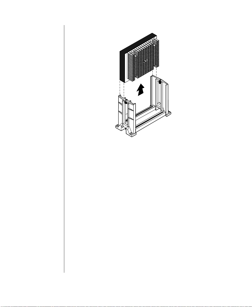
Figure 12: Removing the Processor
5. Place the processor cartridge that you removed in a safe place.
6. Remove the replacement processor cartridge from its protective
wrapping and place it in the cartridge supports for the slot 2 connector.
7. Slide the cartridge all of the way down until it is firmly seated. See
Figure 13.
28 Maintaining and Troubleshooting the Gateway ALR 7300 Server

Figure 13: Installing the Replacement Processor
8. If the processor cartridge does not already have the heatsink attached
to it, attach the heatsink according to the instructions that came with
the processor upgrade kit.
9. Replace the lock bar on the processor support and secure it with the
two screws that you removed in Step 3.
10. Set the jumpers for the new processor configuration (see the section
“Setting the jumpers” on page 33).
11. Close the case, as described in “Closing the system” on page 8.
12. Reconnect the power cord and turn on the system.
Installing Components 29

Installing a second processor
The system is compatible with Intel Pentium II Xeon processors.
You can either upgrade the existing Pentium II Xeon processor or install a
second processor of the same speed as the original processor.
When adding a processor, order a Pentium II Xeon processor upgrade kit.
The kit includes the processor, a heat sink, and aVRM.
It is critical that a heat sink be installed on each Pentium II Xeon processor.
The processor overheats and fails if it is not cooled sufficiently. The heat
sink provided with the processor on the system provides all necessary
cooling for the processor.
For the latest details on the availability of the upgrade kits, contact one of
the sources listed in the Assistance Resources document.
To Install a Second Processor
Turn off the system and disconnect the power cord.
1.
Open the case (“Opening the system” on page 3), observing the static
2.
electricity precautions in “Static electricity precautions” on page 2.
Remove the lock bar from the processor supports as shown in
3.
Figure 11 on page 27.
Remove the Terminator Card from the system board (see Figure 14).
4.
30 Maintaining and Troubleshooting the Gateway ALR 7300 Server

Figure 14: Removing the Terminator Card
5. Align the new Pentium II Xeon SEC cartridge into the CPU 2
connector and press it firmly into place. See Figure 15.
Installing Components 31

Figure 15: Installing the Second Processor
6. Place the lock bar on top of the supports and secure it by inserting and
tightening the two screws you removed in Step 3.
7. Set the jumpers for the new processor configuration (see the section
“Setting the jumpers” on page 33).
8. Insert the VRM into the connector provided until the release clips
click into place.
9. Close the case, as described in “Closing the system” on page 8.
10. Reconnect the power cord and turn on the system.
32 Maintaining and Troubleshooting the Gateway ALR 7300 Server

Setting the jumpers
The system board jumpers let you change several system functions.
Jumpers are set to the default positions at the factory. You may need to
change the jumper settings to perform the following functions:
Set processor/bus speed settings
•
Clear CMOS memory
•
Processor speed jumper
The system board supports a range of processor speeds, which are set by
changing jumpers. If you upgrade your processor, you may need to change
jumper settings. The Processor Speed jumper (JP22) configuration block
lets you set the processor speed.
The system automatically detects the bus speed supported by the processor
and uses the jumper settings in conjunction with the detected bus speed to
set the processor speed. If two processors are present and they support
different speeds, the system operates at the slower speed. Move the jumper
shunts on jumper block JP22 to connect the jumper pins according to the
table below. Processor speeds are given in relation to bus speeds of
66MHz/100MHz.
Installing Components 33

Important!
If the error message
“update table not found for
CPUxx, Stepping xxxx”
displ ays at boot up, run the
MULO ADE R uti l ity loca t ed
on the disk included with
your processor kit. This
messag e ma y oc cu r u nder
the f ol lo wi n g con di tio ns :
When a ne w proc es sor has
been added that does not
incl ude th e st e ppi ng
information in the table.
When the BIOS is flashed,
it may re mo v e the st ep pi ng
information form the table
which will cause the error
messag e t o ap pe ar.
Clear CMOS jumper
The Clear CMOS jumper (JP15) lets you clear all current values in
complimentary metal-oxide semiconductor (CMOS) memory (see “System
Board Components” on page 14 for the location of the jumper). CMOS
memory stores all of the BIOS Setup information and settings. Clearing the
CMOS memory restores all setup values to the original system defaults.
A jumper shunt connecting pins 1 and 2 sets the jumper for normal
operation. A jumper shunt connecting pins 2 and 3 sets the jumper to clear
the CMOS memory at the next system boot.
To Clear CMOS Memory
1. Restart the server and press
2. Write down the current BIOS configuration settings for later
reference.
3. Turn off the system and disconnect the power cord.
4. Open the case (“Opening the system” on page 3), observing the static
electricity precautions in “Static electricity precautions” on page 2.
to enter the BIOS Setup utility.
2
F
5. Move the jumper shunt on the Clear CMOS jumper (JP15) to connect
pins 2 and 3.
6. Reconnect the power cord and turn on the system. Wait until the
system boots and you see the message that confirms the CMOS
memory has been cleared.
7. Turn off the system again and disconnect the power cord.
8. Move the jumper shunt on the Clear CMOS jumper (JP15) back to its
normal position connecting pins 1 and 2.
9. Close the case, as described in “Closing the system” on page 8.
10. Reconnect the power cord and turn on the system.
Clearing the CMOS memory clears all passwords and all configuration
settings. You must reset any necessary values in BIOS Setup after you clear
CMOS memory.
34 Maintaining and Troubleshooting the Gateway ALR 7300 Server

Installing memory and hard ware
Installing memory
The system board supports up to 2 GB of RAM in ECC SDRAM DIMMs.
The system board is configured with 4 DIMM banks. You can fill Bank 0,
Bank 1, Bank 2, or Bank 3 or a combination of banks with DIMMs. No
jumper settings are required for the memory size or type because this
information is automatically detected by the BIOS.
Refer to the section “DIMM configurations” on page 114 for valid memory
configurations. You may select any combination that provides the total
RAM required by your system and applications.
To Install DIMMs
Turn off the system and disconnect the power cord.
1.
Open the case (“Closing the system” on page 8), observing the static
2.
electricity precautions in “Static electricity precautions” on page 2.
Pull open the socket clamps on each side of the DIMM socket (see
3.
Figure 16).
Important!
In order to reach 2 GB of
RAM, you must install 512
MB DIMMs. At the time this
manual was published, 512
MB DIMMs were not readily
available. These DIMMs had
not been tested with this
system at this time. This
manual assumes that the
512 MB DIMMs will conform
to published standards and
that no significant problems
will be discovered in testing.
Figure 16: Opening the DIMM Socket Clamps
Align the two notches in the DIMM with the two notches in the
4.
DIMM socket (see Figure 17) and insert the DIMM into the socket.
Installing Components 35

Figure 17: Inserting the DIMM
5. Gently press the DIMM into the socket until it is firmly seated.
(Inserting the DIMM automatically locks the socket clamps on each
end of the DIMM.)
6. Close the case, as described in “Closing the system” on page 8.
7. Reconnect the power cord and turn on the system.
To Remove DIMMs
Caution!
Nev e r try to re move a
DIMM w ithout releasing the
clamps. You may break the
sock e t, ca us in g se rious
damage.
1. Gently push out the plastic socket clamps on each end of the DIMM.
The DIMM should pop up slightly from the socket (see Figure 18).
Figure 18: Releasing the DIMM Socket Clamps
36 Maintaining and Troubleshooting the Gateway ALR 7300 Server

2. Carefully lift the DIMM out of the socket (see Figure 19).
Figure 19: Removing the DIMM
3. Store the DIMM in a static-free container.
Adding and replacing driv es
The case must be opened to add or replace drives (such as disk drives and
CD-ROM drives) in the system. Refer to “Opening the system” on page 3
for instructions on opening and closing the case.
Replacing a 3.5-inch drive in the front drive bay
The 3.5-inch drives are secured to a metal mounting bracket, which enables
easy installation and removal from the system chassis. This bracket
supports a 3.5-inch diskette drive which was installed at the factory. There
is space in the bracket for a second front-accessible drive and up to two
internally accessible one inch tall 3.5-inch drives.
To Replace the 3.5-inch Diskette Drive
1. Turn off the system and disconnect the power cord.
2. Open the case (“Opening the system” on page 3), observing the static
electricity precautions in “Static electricity precautions” on page 2.
Installing Components 37

3. Locate the 3.5-inch drive bracket.
4. Disconnect the power and data cables from the back of the drive that
you want to replace, noting their location and orientation. (You will
reconnect these cables after you install the new drive.)
5. Remove the screws securing the drive bracket to the system chassis,
and remove the drive bracket from the chassis. Doing so also removes
the 3.5-inch metal filler panel from the front of the drive bracket (see
Figure 20).
Figure 20: Removing the 3.5-inch Drive Bracket
6. Remove the screws securing the 3.5-inch drive to the bracket, and then
remove the 3.5-inch drive (see Figure 21).
38 Maintaining and Troubleshooting the Gateway ALR 7300 Server

Figure 21: Removing the 3.5-inch Drive
7. Place the new 3.5-inch drive in the mounting bracket (see Figure 22).
Figure 22: Installing the New 3.5-inch Drive
8. Secure the drive to the mounting bracket using the screws you
removed in Step 6.
Installing Components 39

9. Place the drive bracket in the chassis (see Figure 23). If you are
installing a second front-accessible drive, do not reinstall the 3.5-inch
metal filler panel when you reinstall the drive bay in the chassis.
Figure 23: Replacing the Drive Bracket
10. Secure the drive bracket to the chassis with the screws you removed in
Step 5.
11. Connect the power and data cables to the 3.5-inch drive, making sure
the cables match their original position. (See drive documentation for
proper drive jumper settings and cable orientation.)
12. Close the case, as described in “Closing the system” on page 8.
13. Reconnect the power cord and turn on the system.
40 Maintaining and Troubleshooting the Gateway ALR 7300 Server

Installing a drive in the 5.25-inch drive ba y
The 5.25-inch drive bay supports a CD-ROM drive, disk drive, or other
5.25-inch device.
To Install a Drive in the 5.25-inch Drive Bay
1. Turn off the system and disconnect the power cord.
2. Open the case (“Opening the system” on page 3), observing the static
electricity precautions in “Static electricity precautions” on page 2.
3. Locate the 5.25-inch drive bay.
4. If no drive is installed in the drive bay, remove the metal drive bay
cover from the front of the 5.25-inch drive bay. Also, remove the
plastic drive bay cover on the front bezel.
5. If you are replacing an existing drive, disconnect the power and data
cables from the drive, noting their location and orientation. (You will
reconnect these cables after you install the new drive.)
6. Squeeze the tabs at the ends of the guide rails in toward the center of
the drive and pull the drive out of the chassis (see Figure 24).
Installing Components 41

Guide r a il
Tab
Figure 24: Removing a 5.25-inch Drive
7. Remove the screws that secure the drive rails to the drive and remove
the rails.
8. Mount the guide rails to the new drive using the screws you removed
from the old drive.
9. Align the guide rails with the rail guides in the drive bay and slide the
drive all of the way into the bay. The tabs on the rails will click into
place when the drive is fully inserted (see Figure 25).
42 Maintaining and Troubleshooting the Gateway ALR 7300 Server

Figure 25: Installing a Drive in the 5.25-Inch Drive Bay
10. Connect the power and data cables to the back of the drive. (See drive
documentation for proper drive jumper settings and cable orientation.)
11. Close the case, as described in “Closing the system” on page 8.
12. Reconnect the power cord and turn on the system.
13. Run the configuration software that came with the drive, if required.
14. The system should automatically recognize the new drive. If it does
not, you may need to set jumpers on the drive or change settings in the
BIOS Setup utility.
Installing Components 43

Replacing the RAID cage in the 5.25-inch drive bay
The Quick Hot-Swap Drive Cage consists of a drive cage, a locking door,
and all the necessary hardware to install it in the system. Each cage
supports three drives. Begin cage installation from the bottom drive bay.
Figure 26: Hot-Swap Drive Cage
To Replace the RAID Cage
1. Remove the side panel as described in “Removing the side panel” on
page 3.
2. Disconnect all cables connecting the RAID Cage to other system
components.
3. Remove the drives:
A. Pull the latching clips outward to release the drive from the RAID
Cage (see Figure 27).
44 Maintaining and Troubleshooting the Gateway ALR 7300 Server

Figure 27: Removing the SCSI Drives
B. Pull the drive out of the drive cage.
C. Place the drive in a safe place, preferably in an anti-static bag.
D. Repeat steps a–c for all drives in the drive cage.
4. Remove the old RAID Cage by pressing the tabs on the slide rails
toward the center of the cage and pulling the cage out of the 5.25-inch
drive bay (see Figure 28).
Installing Components 45

Figure 28: Removing the RAID Cage
Installing the New RAID Cage
1. Slide the new drive cage into the drive bracket as shown in Figure 29.
46 Maintaining and Troubleshooting the Gateway ALR 7300 Server
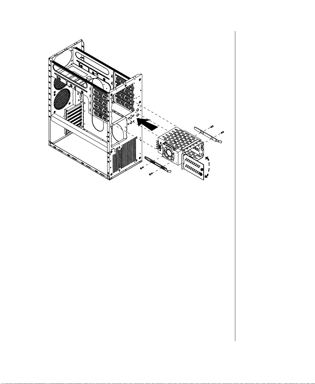
Figure 29: Installing the RAID Cage
2. Connect all cables that connect the RAID Cage and its backplane to
other system components.
3. Reinstall the SCSI drives in the new RAID cage by aligning the rails
and sliding them all the way into the cage (see Figure 30).
Installing Components 47

Important!
Each drive has a Drive
Number label affixed to the
front of the drive. The drive
number on the label
corresponds to the device's
SCSI ID. Drives must be
installed in ascending order
starting from the bottom
bay.
Figure 30: Replacing the SCSI Drives
4. Secure the drives by closing the latching clips.
Replacing a hard disk in the rear driv e bay
The hard disk is secured to a metal mounting bracket, which enables the
drive to be easily installed and removed from the system chassis. This
procedure refers to the internal 3.5-inch drive bay, not to the 3.5-inch bay at
the front of the chassis.
To Replace a Hard Drive in the Rear Drive Bay
1. Turn off the system and disconnect the power cord.
2. Open the case (“Opening the system” on page 3), observing the static
electricity precautions in “Static electricity precautions” on page 2.
3. Locate the hard disk assembly beneath the power supply at the rear of
the chassis.
48 Maintaining and Troubleshooting the Gateway ALR 7300 Server

4. Disconnect the data and power cables from the hard disk drive, noting
their location and orientation. (You will reconnect these cables when
you install the new hard drive.)
5. Remove the screws that attach the hard disk mounting bracket to the
chassis, and remove the bracket from the chassis (see Figure 31).
Figure 31: Removing the Hard Disk Bracket and Drive
6. Remove the screws that attach the hard drive to the mounting bracket
and remove the hard drive (see Figure 31).
7. Secure the new hard drive to the mounting bracket using the screws
you removed in Step 6 (see Figure 32).
Installing Components 49

Figure 32: Installing a Hard Drive in the Rear Drive Bay
8. Place the hard disk assembly into the chassis and secure it to the
chassis using the screws you removed in Step 5 (see Figure 32).
9. Connect the data and power cables to the hard drive, making sure the
cables match their original position. (See the drive documentation for
proper drive jumper settings and cable orientation.)
10. Close the case, as described in “Closing the system” on page 8.
11. Reconnect the power cord and turn on the system.
12. The system should automatically recognize the new drive. If it does
not, you may need to set jumpers on the drive or change settings in the
BIOS Setup utility.
50 Maintaining and Troubleshooting the Gateway ALR 7300 Server

SCSI cable kit installation
The following section describes how to install the SCSI cable kit from the
integrated onboard SCSI connector on the system board to the rear panel of the
chassis.
The following tools are required to complete the installation:
Phillips screwdriver
•
Straight blade screwdriver
•
Anti-static wristband
•
To install the SCSI cable kit:
Power down the system and remove the power cord(s).
1.
Remove the parts from the SCSI Cable Kit.
2.
Remove the two screws from the rear of the left side cover.
3.
Slide the side cover back slightly, then lift it out and off.
4.
Using the straight bladed screwdriver, remove the punchout section
5.
(insert the blade of the screwdriver into the slot in the punchout, then
pry back and fourth until loose).
SCSI cable
Integrated SCSI
connector
Figure 33: Installing the SCSI Cable Kit
6. One end of the SCSI cable is attached to a bracket containing two threaded
holes. From the inside of the system, hold this end of the cable up to the
opening created when the punchout was removed.
System board
Caution!
T o help avoid possible
damage to your computer
from st ati c el ec tr ic ity, follo w
the anti-static procedures
outli ned in the Maint ena nce
and Troubl es ho ot ing G u ide
for your system every time
you work inside your
computer.
7. Using the two small screws included in the SCSI Cable Kit, secure the SCSI
cable/bracket to the rear panel of the chassis.
Installing Components 51

8. Plug the other end of the SCSI cable into the appropriate SCSI connector on
the system board.
9. Arrange the ribbon cable so that it doesn’t interfere with chassis or CPU fans,
or block airflow through the system.
10. Reinstall the left side cover of the system and replace the two screws.
11. Plug in the system power cord(s) and power up the system.
Adding an e xpansion c ard
The system board has seven (7) expansion slot connectors. The system
board accepts two types of expansion cards: ISA and PCI. Some of the PCI
expansion slots are designed to allow the slot to be shared with a special
purpose expansion card such as a RAIDport card.
Some ISA expansion cards have jumpers or switches that set interrupts and
I/O addresses. They come with instructions that explain how to set them to
avoid hardware conflicts. Follow the instructions carefully.
Refer to Figure 7 on page 14 for the installation locations.
To Install an Expansion Card
Set any jumpers and switches on the card, if required in the card
1.
instructions.
Turn off the system and disconnect the power cord.
2.
Open the case (“Opening the system” on page 3), observing the static
3.
electricity precautions in “Static electricity precautions” on page 2.
Locate an open slot of the correct type.
4.
52 Maintaining and Troubleshooting the Gateway ALR 7300 Server

5. Remove and retain the screw securing the expansion port cover to the
rear cover. Keep the port cover for reinstallation in case you ever need
to remove the card (see Figure 34).
Figure 34: Installing an Expansion Card
Important!
For full length cards, make
certain that the end of the
card is aligned with the
correct slot in the card
guide. When the card is fully
inserted, the plastic retaining
clip will snap back out to
hold the end of the card in
position.
6. Firmly insert the edge of the expansion card into the slot.
7. After seating the card firmly, secure it to the chassis by installing the
screw you removed in Step 5 through the mounting bracket at the end
of the card.
8. If required, connect cables to the card (see card documentation for
proper jumper settings and cable orientation)
9. Close the case, as described in “Closing the system” on page 8.
10. Reconnect the power cord and turn on the system.
It may be necessary to reconfigure your system after installing some
expansion cards. You may also need to install software that came with the
card. Check the card documentation for additional information.
Installing Components 53

Remo ving an e xpansion card
Removing an expansion card may require you to run software to
reconfigure the system.
To Remove an Expansion Card
1. Turn off the system and disconnect all power cords and peripheral
devices.
2. Open the cover as described in “Opening the system” on page 3,
following all static electricity precautions as described in “Static
electricity precautions” on page 2.
3. If necessary, disconnect any cables connected to the expansion card.
4. Remove the screw that secures the card and its bracket to the back
panel of the server (see Figure 35).
Figure 35: Removing the Expansion Card Screw
5. For full-length cards, press the retaining latch on the card guide in,
until it clicks into the retracted position (see Figure 36).
54 Maintaining and Troubleshooting the Gateway ALR 7300 Server

Retaining
Release
button
latch
Figure 36: Pressing the Retaining Latch
6. Gently but firmly pull the expansion card out of the chassis.
7. Press the release button on the card guide to return the retaining latch
to the extended position.
8. Place an expansion port cover over the empty slot and secure it with
the screw you removed earlier.
9. Replace the cover, reconnect the peripherals and power cord, and turn
on the system.
Installing Components 55

Caution!
There is a da ng er of
explosion if the battery is
incorr ec tly r e place d.
Replac e th e b at tery on ly
with the same or equivalent
type rec omm en de d b y the
manufacturer. Dispose of
used batteries according to
the manufacturer’s
instructions.
Replacin g the battery
The battery provides power for the system real-time clock and CMOS
RAM, which holds the system configuration information.
To Replace the Battery
1. Restart the computer and start the BIOS Setup program by pressing
when you are prompted to do so.
2. Write down the CMOS values from the Main Setup screen so you can
reenter them after you replace the battery. (For more information about
the setup program, see Chapter 4, “Using the BIOS Setup Utility” on
page 62.)
3. Turn off the system and disconnect the power cord.
4. Open the case (“Opening the system” on page 3), observing the static
electricity precautions in “Static electricity precautions” on page 2.
5. Locate the battery on the system board, see Figure 7 on page 14. The
battery is circular and has the positive pole mark (+) on the top.
6. Gently pull the battery from its socket, and press the new battery in the
socket with the positive pole (+) up (see Figure 37). Be sure you have
pressed the battery down far enough for it to contact the base of the
socket.
2
F
56 Maintaining and Troubleshooting the Gateway ALR 7300 Server

Figure 37: Removing the Battery
7. Close the case, as described in “Closing the system” on page 8.
8. Reconnect the power cord and turn on the system.
9. Enter the BIOS Setup program and verify that the system
configuration is correct using the data you recorded in Step 2.
If the CMOS data is not correct, change the information in the setup screens
as necessary.
Troubleshooting the battery installation
If you have problems after installing the new battery, try each of the items
listed below, replacing the cover and restarting the computer after each try.
Turn off the system and ensure that all exterior cables are attached
•
to the correct connectors and secured.
Check to be sure that all power switches are on. If the system is
•
plugged into a power strip or surge protector, be sure it is turned on
also.
Enter the BIOS Setup program and compare the settings on the
•
screen with your notes or the system hardware manuals. Correct
any discrepancies.
Installing Components 57

Turn off the system, remove the cover, and verify that all cables
•
inside the case are attached securely. Also, make sure that the
colored cable edges are aligned correctly and that the connectors
do not miss any pins. Disconnect and reconnect the cables, and
then replace the cover carefully so as not to disturb any cables.
Turn off the system, remove the cover and, if you have the proper
•
test equipment, verify that the new battery has power. (It is
possible, although highly unlikely, that your new battery is
defective.)
If these procedures fail to correct the problem, contact Technical Support.
When everything works properly, close the case as described in “Closing
the system” on page 8, reconnect the power cord, and turn on the system.
Installing software and drivers
Installing software and drivers is usually specific to the operating system
you run on the system. However, some tips on installing drivers or other
software in critical situations or under particular circumstances are provided
below.
Installi ng the video driv ers
The integrated video controller on the system board uses standard drivers
provided with the system utilities diskettes. For those running Windows NT
in particular, use the driver provided on the utilities diskettes (Cirrus Logic
Windows NT 4.0 v1.40 diskette) not those provided on the Windows NT
installation CD-ROM. The drivers provided on the Windows NT CD-ROM
may not function correctly.
Video driver installation varies depending on the operating system that you
run on the server. Refer to the documentation for the operating system for
specific instructions.
If you are using an add-in video controller, the drivers should have
accompanied the controller card. See the documentation that accompanied
the controller card for instructions and information regarding the drivers for
an add-in video card.
58 Maintaining and Troubleshooting the Gateway ALR 7300 Server

NetW are 4.11 driv ers and Seagate Bac kup Exec issues
NetWare 4.11 driver issues:
When installing the second instance driver for the second SCSI controller,
the server will generate interrupts which hang the server. To resolve this
issue, replace the MPS14.PSM file that is installed during the NetWare 4.11
installation with an updated version of the file. The updated file can be
obtained from the Netware Service Pack 5 utility patch provided by Novell.
The following are two methods that can be used to updated the
MPS14.PSM file:
1. After NetWare is installed and before loading the second on-board
SCSI driver, the updated MPS14.PSM f ile can be copied to the
C:\NWSERVER subdirectory to overwrite the older version placed
during installation. Restart the server and the second on-board SCSI
driver will load successfully.
2. During the NetWare installation, select SMP support, a message to
install an unlisted PSM file will display. Path to the location of the
updated PSM file and load it. Once loaded, the updated PSM file will
automatically be copied to the NetWare installation directory. Once
the file has been copied you can successfully load the second on-board
SCSI driver.
Seagate Backup Ex ec issues:
Once Seagate Backup Exec has been installed and the program started, the
CLIB and DSAPI modules report errors while loading. Backup Exec will
continue to run after the errors appear. Backup Exec recommends that these
files be updated to a later version. The updated files can be obtained from
Novell’s website at the following location:
http://support.novell.com/cgi-bin/search/download?/pug/updates/nw/i
nw411/libuph.exe&sr
The update files are CLIB.NLM and DSAPI.NLM.
Installing Components 59

60 Maintaining and Troubleshooting the Gateway ALR 7300 Server

Chapter 4:
BIOS Setup
About the BIOS Setup Utility............................... 62
Using the BIOS Setup Utility................................ 62
Updating the BIOS ................................................ 81
4

About the BIOS Setup Utility
The computer BIOS has a built-in program that lets you set many basic
system characteristics. These settings are stored and saved even when the
power is off. This chapter contains information about this setup utility and
is intended to serve as a guide so that you can make changes to your system
BIOS when necessary.
Many of the screen examples that you see in this chapter are identical to
what you see on your monitor; however, you may have a system with a
newer BIOS version than the one described in this manual. In that case,
some of the examples may differ somewhat from what you see, but the
screens are similar enough that you should have no trouble getting the
information that you need.
Using the BIOS Setup Utility
The computer BIOS has a built-in setup utility that lets you configure
several basic system characteristics. The settings are stored in
battery-backed CMOS memory and are retained even when the power is
off.
To enter the setup utility, restart the system and then press
prompted on screen during the startup process. Upon entering setup, the
Main Setup screen opens.
Figure 38: BIOS Menu Navigation Keystrokes
The lower section of all screens provides information about keystrokes
necessary to access help, navigate through the menus, and perform other
functions.
Help—Press
•
item is only usable in a submenu.
Exit—Press
•
Select Item—Press the up arrow or down arrow keys to move to
•
the next or previous menu item.
62 Maintaining and Troubleshooting the Gateway ALR 7300 Server
to get information about the selected item. This
1
F
to back out of any field.
SC
E
F
when
2

• Select Menu
—Use the left arrow and right arrow keys to move
between the six main menus (Main, Advanced, Security, Power,
Boot and Exit).
• Change Values
—Use the plus (+) key or the minus (-) key to
toggle through the available options for the selected item.
• Select
>
Sub-Menu
— Pressing
when a sub-menu is
NTER
E
highlighted takes you to that sub-menu.
• Setup Defaults
—Press
to set the setup parameters to their
9
F
factory default values. A submenu appears, asking you to press
either
• Save & Exit
ignore all changes. A submenu appears, asking you to press
to save the changes or
to load the defaults or
NTER
E
—Press
to skip.
SC
E
to exit the setup utility and either save or
10
F
to ignore the changes and exit.
SC
E
NTER
E
Main menu screen
The main menu screen allows you to access the most common setup fields.
Figure 39: Main Menu Screen
BIOS Setup 63

• System Time
clock in the format HH:MM:SS.
lets you set the system time. Use a twenty-four hour
• System Date
MM:DD:YYYY.
• Legacy Diskette A:
installed as drive A. The options are
720 kB, 3 ½”; 1.44/1.25 MB, 3 ½”;2.88 MB, 3 ½”; Not installed;
and
Disabled
• Legacy Diskette B:
installed as drive B. The options are
720 kB, 3 ½”; 1.44/1.25 MB, 3 ½”;2.88 MB, 3 ½”; Not installed;
and
Disabled
• Primary Master:
to setup the primary master hard disk drive. Details of this screen
are provided in the section “Hard disk drive setup screen” on
page 65.
• Primary Slave:
setup the primary slave hard disk drive. Details of this screen are
provided in the section “Hard disk drive setup screen” on page 65.
• Secondary Master:
you to setup the secondary master hard disk drive. Details of this
screen are provided in the section “Hard disk drive setup screen”
on page 65.
lets you set the system date, using the format
allows you to select the type of diskette drive
360 kB, 5 ¼”; 1.2 MB, 5 ¼”;
.
allows you to select the type of diskette drive
360 kB, 5 ¼”; 1.2 MB, 5 ¼”;
.
opens the Primary Master screen to permit you
opens the Primary Slave screen to permit you to
opens the Secondary Master screen to permit
• Secondary Slave:
to setup the secondary slave hard disk drive. Details of this screen
are provided in the section “Hard disk drive setup screen” on
page 65.
• System Memory:
detected.
• Extended Memory:
detected.
64 Maintaining and Troubleshooting the Gateway ALR 7300 Server
opens the Secondary Slave screen to permit you
shows the amount of base system memory
shows the amount of extended memory

Hard disk drive setup screen
The hard disk drive setup screen appears whenever the Pr imar y Mast er ,
Prim ary S la ve, Secondary M as te r,
selected from the main menu screen.
or Secondary Slave fields are
Figure 40: Example Hard Disk Drive Setup Screen
Type offers the following options:
•
• User - selecting this option brings up a sub-menu where you
can enter the
Capaci ty
generally available from the documentation for the drive or the
drive label itself.
• Auto - selecting this option automatically configures the drive
based on information from the drive itself.
• CD-ROM - select this option if the drive is a CD-ROM.
• None - “Auto” has been unable to supply the drive type or you
have deliberately selected “None,” disabling any drive that
may be installed.
Cylinders, Heads, Sector s
of the drive you are configuring. These values are
Maxim um
and
BIOS Setup 65

• Multi-Sector Transfers:
enabling this option allows multiple
sector data transfers on compatible drives. The options are
Disabled, Standard, 2 Sectors, 4 Sectors, 8 Sectors,
16 Sectors
.
and
• LBA Mode Control:
enabling this option causes Logical Block
Addressing to be used in place of Cylinders, Heads and Sectors.
The options are
• 32 Bit I/O:
Enabled
enabling this option allows 32-bit communication
and
Disabled
.
between the processor and the IDE controller. The options are
Enabled
and
Disabled
• Transfer Mode:
.
selects the method for moving data to and from
the drive. The options listed are those supported by the drive and
the platform; either
and
Fast PIO 4
3,
FPIO4/DMA2
• Ultra DMA Mode:
transfer rate with compatible drives. The options are
Mode 1,
and
Standard, F ast PIO 1, F as t PIO 2, Fast PIO
; or
Standard, FPIO3/DMA1,
and
.
enabling this option allows a faster data
Mode 2
.
Mode 0,
66 Maintaining and Troubleshooting the Gateway ALR 7300 Server

Advanced menu screen
The advanced menu screen allows you to access a large number of
advanced features. Many of these features can cause the system to
malfunction if set incorrectly. Do not change these settings unless you must.
Figure 41: Advanced Menu Screen
Plug and Play O/S: specifies whether the operating system is
•
compatible with Plug and Play. The options are
Reset Configuration Data: selecting Yes causes the system to
•
clear its configuration data and automatically configure all PnP
devices at bootup. Selecting
existing configuration information.
Use Multiprocessor Specification: configures the multiprocessor
•
specification for compatibility reasons. Specification 1.4 allows
extended bus definitions and is required to permit a secondary PCI
bus to work without a bridge. However, some operating systems
require Specification 1.1 for compatibility reasons.
No causes the system to use the
Yes and No.
BIOS Setup 67

• Large Disk Access Mode:
if you are using DOS or one of the DOS-based operating
DOS
systems. Select
if you are using another operating system
Other
options include
DOS
and
Other
such as UNIX. A large disk is considered one that has more than
1024 cylinders, 16 heads, or 63 tracks per sector.
. Select
• Local Bus IDE Adapter
the onboard IDE adapter. The options are
Second ary
, and
Both
• Resource Configuration
enables or disables the two channels of
Disable, Primary
.
opens the Resource Configuration
screen. Details of this screen are provided in the section, “Resource
configuration screen” on page 69.
• Peripheral Configuration
opens the Peripheral Configuration
screen. Details of this screen are provided in the section,
“Peripheral configuration screen” on page 72.
• Keyboard Features
opens the Keyboard Configuration screen.
Details of this screen are provided in the section “Keyboard
features screen” on page 74.
• Cache Memory
opens the Cache Memory Configuration screen.
Details of this screen are provided in the section “Cache memory
screen” on page 75.
• Advanced Chipset Control
screen which contains a single field. The field is
opens the advanced chipset control
ECC Config
which allows you to set the extent of error checking and correction
that the system uses. The options for this field are
and
ECC,
• Embedded PCI SCSI: Channel A
ECC Scrub.
enabling this field turns on
Disabled, EC,
channel A of the optional integrated SCSI adapter. Select the Scan
First option if the server will boot from a hard disk or select the
Scan Last option if the server will boot from a CD-ROM. The
options are
Enabled
and
Disabled
.
,
,
• Embedded PCI SCSI: Channel B
channel B of the optional integrated SCSI adapter. Select the Scan
First option if the server will boot from a hard disk or select the
Scan Last option if the server will boot from a CD-ROM. The
options are
68 Maintaining and Troubleshooting the Gateway ALR 7300 Server
Enabled
and
Disabled
enabling this field turns on
.

• Embedded PCI NIC:
enabling turns on the optional integrated
network interface controller (NIC). The options are
Disabled
• SHM Address
.
: defines the System Hardware Manager (SHM)
address. The options are 1 through 7.
Resource configuration screen
Enabled
and
Important!
The SHM Address is always
1 in stand-alone
configurations.
This screen appears whenever
the advanced menu screen.
Figure 42: Resource Configuration Screen
• Memory Reservation:
This screen allows you to reserve blocks of upper memory for use
by legacy ISA devices. Details of this screen are provided in the
section “Memory Reservation Screen” on page 70.
Resour ce Co nfi gur ati on
is selected off of
opens the Memory Reservation screen.
• IRQ Reservation:
opens the IRQ Reservation screen. This screen
allows you to reserve IRQs for use by legacy ISA devices. Details
of this screen are provided in the section “IRQ Reservation
Screen” on page 70.
BIOS Setup 69

Memory Reservation Screen
This screen appears whenever Memory Re se rv at ion is selected from the
resource configuration screen. It allows you to reserve blocks of memory
for ISA devices.
Figure 43: Memory Reservation Screen
XXXX – XXXX: the specified area of upper memory may be
•
reserved for use by legacy ISA devices. Options are
Reserved.
IRQ Reservation Screen
This screen appears whenever you select IRQ Reservation from the
advanced menu screen. It allows you to manually reserve IRQs for specific
devices.
70 Maintaining and Troubleshooting the Gateway ALR 7300 Server
Available and

Figure 44: IRQ Reservation Screen
IRQx: the specified IRQ may be reserved for use by legacy ISA
•
devices. Options are
Available
and
Reserved
.
BIOS Setup 71

P eripheral configuration screen
This screen allows you to configure the system peripherals.
Figure 45: Peripheral Configuration Screen
Serial Port A: allows you to set the characteristics of serial port A.
•
Options include
• Base I/O Address: displays the base I/O address for
integrated Serial Port A. Using the + or - key displays the
optional addresses available.
• Interrupt: displays the current interrupt for integrated Serial
Port A. Using the + or - key displays the optional interrupts
available.
Serial Port B: allows you to set the characteristics of serial port B.
•
Options include
• Base I/O Address: displays the base I/O address for
integrated Serial Port B. Using the + or - key displays the
optional addresses available.
72 Maintaining and Troubleshooting the Gateway ALR 7300 Server
Enabled, Disabled and Auto.
Enabled, Disabled and Auto.

• Interrupt: displays the current interrupt for integrated Serial
Port B. Using the + or - key displays the optional interrupts
available.
Parallel Port: allows you to set the characteristics of the integrated
•
parallel port. Options include
Controlled
.
Enabled, Disabled, Auto, and OS
• Mode: displays the current parallel port mode. Options
include
and
ECP
Output Only
(Extended Capabilities Port),
.
Bi-directional
• Base I/O Address: displays the base I/O address for the
integrated Parallel Port. Using the + or - key displays the
optional addresses available.
• Interrupt: displays the current interrupt for the integrated
Parallel Port. Using the + or - key displays the optional
interrupts available.
• DMA Channel: displays the current DMA channel used by
the Parallel Port. Using the + or - key displays the optional
channels available.
Floppy Disk Controller: controls the integrated diskette drive
•
controller. Options include
Enable and Disable.
• Base I/O Address: displays the base I/O address for the
integrated diskette controller. Options include
Secondary
.
Primary
and
BIOS Setup 73

Ke yboard features screen
This screen allows you to configure the features of your keyboard.
Figure 46: Keyboard Features Screen
Num Lock: options include Auto, On and Off. Sets the power-on
•
state of the
Key Click: options are Enabled and Disabled. Enable causes an
•
NUM L
OCK
key.
audible click when each key is pressed.
Keyboard Auto-Repeat Rate: determines the rate at which a
•
character repeats if a key is held down. Options are
10/sec, 13.3/sec, 18.5/sec, 21.8/sec, 26.7/sec
Keyboard Auto-Repeat Delay: determines the amount of delay
•
before a pressed key repeats. Options are
, and 1 sec.
sec
74 Maintaining and Troubleshooting the Gateway ALR 7300 Server
2/sec, 6/sec,
, and 30/sec.
1/4 sec , 1/2 sec, 3/4

Cache memory screen
This screen allows you to configure various aspects of the system cache
memory.
Figure 47: Cache Memory Screen
Memory Cache: allows you to disable the L1 and L2 memory
•
caches. Options include
Enabled or Disabled. Normally used to
troubleshoot speed-related problems.
Cache System BIOS Area: controls the caching of the system
•
BIOS area. Options are
Cache Video BIOS Area: controls the caching of the video BIOS
•
area. Options are
Cache Base 0-512K: controls caching of the first 512KB of base
•
memory. Options are
Writ e Pr otec t.
Cache Base 512K-640K: controls caching of the 512KB through
•
640KB area of base memory. Options are
Thr oug h
, Uncached, and Write Protect.
Uncached or Write Protect.
Uncached or Write Protect.
Write B ac k, W ri te Thr o ugh, Uncached and
Write Back, Write
BIOS Setup 75

• Cache Extended Memory Area:
memory above 1 MB. Options are
Writ e Pr otec t,
and
Write Back
.
controls caching of the system
Uncac hed , W rit e Through,
• Cache segments (e.g., C800 - CBFF):
specified segments of memory. Options are
and
Thr ough, Wri te Pr otec t,
• MSCS Support:
Options are
Write Back
Enabled
controls caching of the
Disabled, Write
.
and
Disabled.
support Microsoft Cluster.
Security menu screen
This screen allows you to set system security characteristics.
Enable to
Figure 48: Security Menu Screen
• Supervisor Password:
password. Options are
password has been established).
• User Password:
are
established).
76 Maintaining and Troubleshooting the Gateway ALR 7300 Server
(no password entered) and
Clea r
displays the status of the user password. Options
displays the status of the administrative
(no password entered) and
Clear
(a password has been
Set
Set
(a

• Set Supervisor Password
opens the supervisor password menu. In
this box, the supervisor can enter and verify the password used to
control access to the setup utility. If the supervisor password has
already been set, the supervisor must enter the current password
before being able to enter and verify a new password.
• Set User Password
shows the user password menu. In this box,
you can enter and verify the password used to control access to the
system at boot. If the user password has already been set, you must
enter the current password before you are able to enter and verify a
new password.
• Password on Boot:
when this option is enabled, the system
prompts you for a password before booting the system.
• Fixed Disk Boot Sector:
allows you to write-protect the boot
sector of the primary boot disk to protect the system from viruses.
Options for this field are
• Diskette Access:
include
supervisor) and
Superv isor
Normal
controls access to the diskette drive. Options
(diskette drive is accessible only to the
(diskette drive is accessible to any user).
User
and
Write Protect
.
BIOS Setup 77

Boot menu scre en
This screen allows you to set the order in which the system seeks boot data.
Figure 49: Boot Menu Screen
First Boot Device: designates the device that the system polls first
•
upon boot up. Options include
Removable Devices, A TAPI CD-ROM Drive,
.
Boot
Second Boot Device: designates the device that the system polls
•
second upon boot up, assuming that it finds no boot data on the
previously designated device. Options include
Hard Drive, Removable Devices, ATAPI CD-R OM Drive,
Network Boot.
Third Boot Device: designates the device that the system polls
•
third upon boot up, assuming that it finds no boot data on the
previously designated device. Options include
Hard Drive, Removable Devices, ATAPI CD-R OM Drive,
Network Boot.
78 Maintaining and Troubleshooting the Gateway ALR 7300 Server
Diskette Drive, Hard Drive,
and Network
Diskette Drive,
and
Diskette Drive,
and

• Fourth Boot Device:
designates the device that the system polls
fourth upon boot up, assuming that it finds no boot data on the
previously designated device. Options include
Hard Drive, Removable Devices, ATAPI CD-R OM Drive,
Network Boot
.
Diskette Drive,
and
• Fifth Boot Device:
designates the device that the system polls fifth
upon boot up, assuming that it finds no boot data on the previously
designated device. Options include
Removable Devices, AT API CD-ROM Drive,
.
Boot
• Hard Drive:
displays a list of available hard drives. The system
Diskette Drive, Hard Drive,
and
Network
attempts to boot to the operating system from the first hard drive
on this list. If no operating system is found, the system tries the
next drive listed until an operating system is found or there are no
more hard drives on the list. Use the up and down arrows to select a
device, then press (+) or (-) to move it up or down the list.
• Removable Devices:
displays a list of available removable devices.
The system assigns drive letters to these devices in the order
displayed. To change the sequence and drive letter of a device, use
the up and down arrows to select a device, then press (+) or (-) to
move it up or down the list.
BIOS Setup 79

Exit menu screen
This screen allows you to exit the Setup program or to save any changes you
have made to the BIOS settings.
Figure 50: Exit Menu Screen
Exit Saving Changes: exits BIOS Setup and saves the changes
•
you have entered in the CMOS. The next time you boot the system,
the BIOS configures your system using the new settings.
Exit Discarding Changes: exits BIOS Setup and discards the
•
settings you have entered. The next time you boot the system, the
BIOS configures your system using the old settings.
Load Setup Defaults: displays the setup defaults in cases where
•
the settings have been corrupted or incorrectly modified. Press
to resume the boot, or
values already loaded into the menus.
Discard Changes: restores the CMOS settings previously entered
•
(not the default values) and discards the changes entered in the
current session, without exiting the BIOS Setup.
Save Changes: saves the changes you have made during the
•
current session, without exiting Setup.
80 Maintaining and Troubleshooting the Gateway ALR 7300 Server
F
to run BIOS Setup with the ROM default
2
1
F

Updating the BIOS
Flash memory simplifies distributing BIOS upgrades. If you need a new
version of the BIOS, you can download the BIOS update from the
Technical Support web site and install the new version from a disk.
To Update the BIOS
Enter BIOS Setup by pressing
1.
Write down the settings for each of the fields. (At the end of the BIOS
2.
when prompted during startup.
2
F
update process, you will reset the fields to the default values.)
Exit the BIOS Setup program.
3.
Download the correct BIOS file from the Technical Support web site.
4.
Uncompress the contents of the BIOS file you downloaded, and copy
5.
the contents onto a bootable diskette.
Place the bootable diskette containing the BIOS files into drive A, and
6.
restart the system with the disk in the drive.
At the prompt, type:
7.
PROGGTW
and press
The system asks you if you want to change the BIOS. Press Y and then
8.
press
NTER
E
Once the BIOS files have been loaded, remove the disk from drive A
9.
NTER
E
.
.
and restart the system.
Important!
You may encounter a CMOS
checksum error or other
problem after the system
restarts. Try turning the
system off and then
restarting. CMOS checksum
errors require that you enter
BIOS Setup, check your
settings, save your settings,
and exit setup.
As the system starts up, verify that the correct BIOS version is
10.
reported.
Enter BIOS Setup by pressing
11.
when prompted during startup. Once
2
F
in BIOS Setup, re-enter the values you wrote down at the beginning of
this process.
If you do not set the CMOS values back to the correct values, the
system may function erratically.
BIOS Setup 81

82 Maintaining and Troubleshooting the Gateway ALR 7300 Server

Chapter 5:
Troubleshooting
Introduction............................................................ 84
Computer virus notice........................................... 84
Troubleshooting checklist..................................... 85
CD-ROM problems............................................... 87
Hard disk problems................................................ 88
Memory/Processor problems................................ 89
Modem problems................................................... 90
Peripheral/Adapter problems................................ 91
Printer problems .................................................... 93
System problems ................................................... 94
Video problems...................................................... 95
Error messages....................................................... 98
5

Important!
Under no circumstances
return any equipment
without obtaining a Return
Material Authorization (RMA)
number.
Introduction
If your system does not operate correctly, re-read the instructions for the
procedure(s) you have performed. If an error occurs within an application,
consult the documentation supplied with the software.
This section identifies solutions to common problems. If the suggestions in
this chapter do not resolve your problem, try calling Technical Support.
Computer virus notice
A virus is a program written with malicious intent for the sole purpose of
creating havoc in a computer system. It attaches itself to executable files or
boot sectors, so it can replicate and spread. Some viruses may only cause
the system to beep or display messages or images on the screen. Other
viruses are highly destructive and corrupt or erase the contents of files or
disks. To be safe, never assume any virus is harmless.
Viruses are identified by how they infect the computer.
•
Program Viruse s
.EXE, .OVL, .DRV, .SYS, and .BIN.
•
Macro Viruses
viruses are written in the macro languages certain applications use
to enhance their functionality. These viruses do not infect other
programs or the boot sector.
•
Boot Viruses
FAT, or Partition Table.
•
Multipartite Viruses
infect executable program files such as.COM,
infect the data files of specific programs. These
attach themselves to a Boot Record, Master Boot,
are both program and boot infectors.
84 Maintaining and Troubleshooting the Gateway ALR 7300 Server

Viruses are inactive until the infected program is executed, or a boot record
is read. Thereafter, the virus loads itself into system memory and begins to
copy and spread itself. Diskettes used in a contaminated system can get
infected and, in turn, transfer the virus when used in another system. A
virus can also spread via programs downloaded from bulletin boards or the
Internet.
To Prevent Virus Infection
Obtain an anti-virus program and make it a habit to scan the
•
system regularly.
Make backup copies of all files and write-protect the disks.
•
Obtain all software from reputable sources and always scan new
•
software for any viruses prior to installing files.
If the system has been infected, find and remove the viruses using an
anti-virus program. Then turn off the system for a minimum of 15 seconds
to clear the virus from system RAM. You may want to rerun the anti-virus
software when you turn the system back on the verify that the system is
clean.
T r oubleshooting checklist
Before turning on the system, make sure that:
The power cord is connected to the AC power-in connector and an
•
AC outlet.
The AC outlet is supplying power.
•
If you use a power strip, you have turned it on, and set the circuit
•
breaker.
The voltage selection switch on the system power supply reflects
•
the proper voltage.
Troubleshooting 85

V erifyi ng your confi guration
If your system is not operating correctly, the BIOS may contain an invalid
configuration parameter. Enter the BIOS program and check your
configuration settings.
Trou bleshootin g guidelines
As you troubleshoot your system, keep the following guidelines in mind:
Never remove the system cover while the system is turned on.
•
Do not attempt to open the monitor; it is extremely dangerous.
•
Even if the monitor power is disconnected, stored energy within the
components can cause a painful or harmful shock.
If a peripheral such as the keyboard, mouse, drive, or printer does
•
not appear to work, verify that all connections are secure.
If the system displays an error message on the screen, write it
•
down word-for-word. You may be asked about it when calling
Technical Support.
Only qualified personnel should open the system for maintenance.
•
If you are qualified to maintain the system yourself, make certain
•
you are properly grounded before opening the system chassis. See
“Static electricity precautions” on page 2 for more information on
preventing electrostatic damage to the system.
86 Maintaining and Troubleshooting the Gateway ALR 7300 Server

CD-ROM prob lems
An audio CD produces no sou nd.
Probable Cause Solution
The CD is loaded
incorrectly .
The speakers are not
connected.
The speake r volume is
turned down.
The speakers may be
muted via the
Mult imedia volume
control.
The sound car d may not
be installed correctly.
The speakers may be
faulty.
Make certain the label is faci ng upwar d, and then
try again.
Check the speaker cab les. Mak e certain they are
connected properly and securely.
Check the volume control.
From th e
Accessories
Volume Control
turned up.
Open the system, and then res eat the sound
card. Make certain the cab les are connected
properly.
Connect a set of headphones to the speak er jack
to test the output. If they work, replace the
speakers.
Accessories
), click
menu (
Multimedia
. Make certain the volume is
Start | Programs |
, and then click
Troubleshooting 87

Important!
Some systems do not have
sound cards because sound
capabilities are built into the
system board.
The CD-ROM drive is not recogniz ed by th e system.
Probab le Cause Solution
The CD is not intended
for PC use.
The CD is loaded
incorrectly.
The CD is scratched or
dirty.
The CD-ROM drive
needs to be added as
new hardw are.
The secondary IDE
device m ay be disabled.
The CD cables are not
install ed correctly.
Make certain the CD is PC-compatible.
Make certain the label is facing upward, and
then try again.
Try cleaning the CD with a lint-free cloth. Check
the CD for scr atches.
F rom the Control Panel window (
Control Panel
Follow the directions for adding the drive . If you
are not experienced with this procedure, call
Technical Support.
Restart your compute r, and then press F
enter t h e setup progra m . From the
Configuration | Advanced
IDE Interface
Secondary IDE Status
Open the system and check all cables between
the CD controller and the CD-ROM drive.
), double-c li ck
Auto
to
and make certain the
Add New Hardware
menu, set the
Enabled
is
.
Har d disk problems
Start | Settings |
.
2
to
Peripheral
Secondary
The SCSI drive is not recogniz ed by the system.
Probable Cause Solution
The SCSI bus is not
properly terminated.
The drive is configured
with a conflicting SCSI
address.
The cables are not
connected correctly.
88 Maintaining and Troubleshooting the Gateway ALR 7300 Server
Make certain the last device on the SCSI
chain is properly terminated.
Change the device SCSI address to one that
is not currently used by the system.
Open the system and check the cable
connections.

The IDE driv e is not recogniz ed by t he system.
Probable Cause Solution
The primary IDE device
may be disabled.
The primary IDE device
may be configured
incorrectly.
The drive may not be
configured pro perly.
The drive cabl es are not
connected properl y.
The drive contr oller is
not seated properly.
Restart the server, and then press F
Setup. From the
Advanced
and
menu, set the
Primary IDE Status
Peripheral Configuration |
Primary IDE Interface
Enabled
to
Restart the server, and then press F
Setup. From the
IDE Master
Main
Auto Configured
to
menu, set the
.
Consult the hard disk documentation for
instructions on how to configure the drive.
Open the system and check all cables
connected to the cont roller card.
Open the system and reseat the drive
controller. This possibility is only valid for
2
.
2
Primary
systems that include an add-in drive
control ler.
Memory/Processor problems
Memory errors were detected during system start up .
Probable Cause Solution
Memory was added or
removed, and the new
configuration was not
sav ed in BI OS Setup.
The memory was
install e d in c or re c tl y.
A DIMM is faulty. Replace the DIMM. Third-party diagnostic
Enter BIOS Setup and save the new memory
configuration.
Check the memory for proper seating and
orientation.
program s can help determine which DIMM or
memory segment is failing.
to enter
to enter
Important!
If the error message
“update table not found for
CPUxx, Stepping xxxx”
displ ays at boot up, run the
MULO ADE R uti l ity loca t ed
on the disk included with
your processor kit. This
messag e ma y oc cu r u nder
the f ol lo wi n g con di tio ns :
When a ne w proc es sor has
been added that does not
incl ude th e st e ppi ng
information in the table.
When the BIOS is flashed,
it may re mo v e the st ep pi ng
information form the table
which will cause the error
messag e t o ap pe ar.
Troubleshooting 89

A new pr ocessor is not recogniz ed b y the system.
Probable Cause Solution
The processor wa s
installed incor rec tly or i n
the wrong soc ket.
The processor speed
was not selected on the
system board.
A pin was bent on the
processor during
installation.
Check the installation. The pr ocessor should
be recognized automatically if it was installed
correctly.
If your s ystem board enab les y ou to sel ect t he
processor speed, make sure you have
selected the speed properly.
Remove t he processor and inspec t i t for
damage. If a pin is bent, ver y carefully try to
straighten it.
Modem problems
The modem is n ot recognized by the syst em.
Probable Cause Solution
The modem has not
been added as new
hardware.
The modem is not
connected to a live
phone jack.
The modem is not
configured with a valid
interrupt or address.
The phone jack is
shared by another
modem or telephone.
Add the modem as new hardware.
Make certain the line connected to the
modem is live and pl ugged into the
appropriate port on the modem (line port).
Check the system settings f or possible
conflict s. If one exists, correct the problem by
selecting an a vailable interrupt and addres s.
If the modem shares the j ack with another
device, make certain the other device does
not hav e th e port open (f or i nst ance, s omeone
is on the phone, or another modem is in use).
90 Maintaining and Troubleshooting the Gateway ALR 7300 Server
 Loading...