

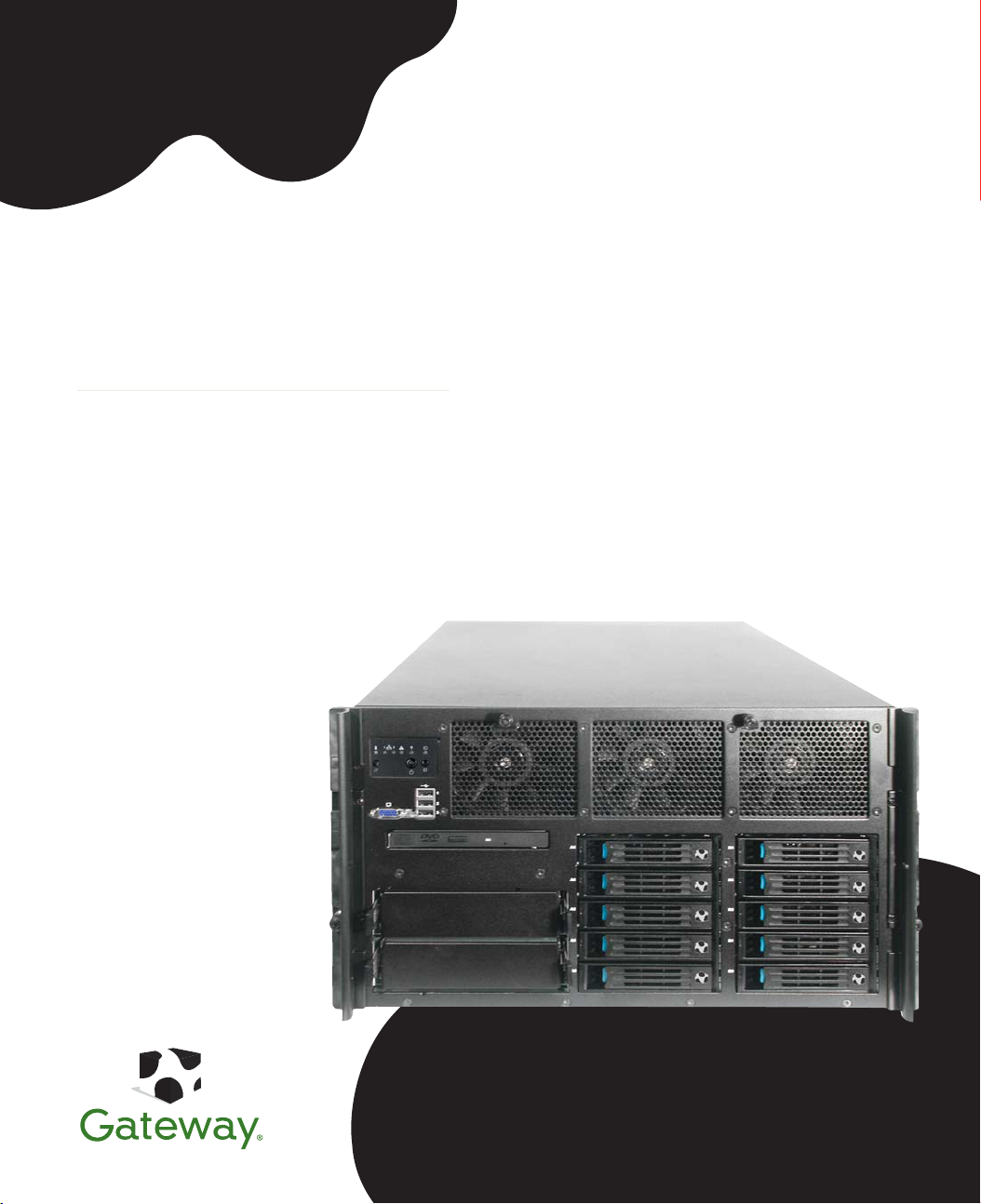
Gateway 9715 Server
USER GUIDE

Contents
1 Checking Out Your Gateway Server . . . . . . . . . . . . . . . . . . . . . . . . . . . . . . . . . . . 1
Front . . . . . . . . . . . . . . . . . . . . . . . . . . . . . . . . . . . . . . . . . . . . . . . . . . . . . . . . . . . . . . . . . . . . 2
Control panels . . . . . . . . . . . . . . . . . . . . . . . . . . . . . . . . . . . . . . . . . . . . . . . . . . . . . . . . . 2
Back . . . . . . . . . . . . . . . . . . . . . . . . . . . . . . . . . . . . . . . . . . . . . . . . . . . . . . . . . . . . . . . . . . . . 3
Interior . . . . . . . . . . . . . . . . . . . . . . . . . . . . . . . . . . . . . . . . . . . . . . . . . . . . . . . . . . . . . . . . . . 4
System board . . . . . . . . . . . . . . . . . . . . . . . . . . . . . . . . . . . . . . . . . . . . . . . . . . . . . . . . . . . . . 5
Left side . . . . . . . . . . . . . . . . . . . . . . . . . . . . . . . . . . . . . . . . . . . . . . . . . . . . . . . . . . . . . . 5
Right side . . . . . . . . . . . . . . . . . . . . . . . . . . . . . . . . . . . . . . . . . . . . . . . . . . . . . . . . . . . . . 6
Getting Help . . . . . . . . . . . . . . . . . . . . . . . . . . . . . . . . . . . . . . . . . . . . . . . . . . . . . . . . . . . . . . 7
System Companion CD . . . . . . . . . . . . . . . . . . . . . . . . . . . . . . . . . . . . . . . . . . . . . . . . . . 7
Gateway Web site . . . . . . . . . . . . . . . . . . . . . . . . . . . . . . . . . . . . . . . . . . . . . . . . . . . . . . 7
2 Setting Up Your Server . . . . . . . . . . . . . . . . . . . . . . . . . . . . . . . . . . . . . . . . . . . . . . . . 9
Setting up the hardware . . . . . . . . . . . . . . . . . . . . . . . . . . . . . . . . . . . . . . . . . . . . . . . . . . . 10
Mounting your server into a cabinet . . . . . . . . . . . . . . . . . . . . . . . . . . . . . . . . . . . . . . . 10
Converting to pedestal configuration . . . . . . . . . . . . . . . . . . . . . . . . . . . . . . . . . . . . . . . 11
Protecting from power source problems . . . . . . . . . . . . . . . . . . . . . . . . . . . . . . . . . . . . . . . 15
Starting your server . . . . . . . . . . . . . . . . . . . . . . . . . . . . . . . . . . . . . . . . . . . . . . . . . . . . . . . 16
Understanding the power-on self-test . . . . . . . . . . . . . . . . . . . . . . . . . . . . . . . . . . . . . . 19
Controlling your server . . . . . . . . . . . . . . . . . . . . . . . . . . . . . . . . . . . . . . . . . . . . . . . . . . . . . 20
Local control . . . . . . . . . . . . . . . . . . . . . . . . . . . . . . . . . . . . . . . . . . . . . . . . . . . . . . . . . 20
Remote control . . . . . . . . . . . . . . . . . . . . . . . . . . . . . . . . . . . . . . . . . . . . . . . . . . . . . . . 20
Turning off your server . . . . . . . . . . . . . . . . . . . . . . . . . . . . . . . . . . . . . . . . . . . . . . . . . . . . 24
Setting up the operating system . . . . . . . . . . . . . . . . . . . . . . . . . . . . . . . . . . . . . . . . . . . . . 25
Initial hardware settings . . . . . . . . . . . . . . . . . . . . . . . . . . . . . . . . . . . . . . . . . . . . . . . . . . . . 26
Configuring SCSI features . . . . . . . . . . . . . . . . . . . . . . . . . . . . . . . . . . . . . . . . . . . . . . . . . . 27
3 Managing and Maintaining Your Server . . . . . . . . . . . . . . . . . . . . . . . . . . . . . . 35
System administration . . . . . . . . . . . . . . . . . . . . . . . . . . . . . . . . . . . . . . . . . . . . . . . . . . . . . 36
Gateway Server Manager . . . . . . . . . . . . . . . . . . . . . . . . . . . . . . . . . . . . . . . . . . . . . . . 36
Local control panel . . . . . . . . . . . . . . . . . . . . . . . . . . . . . . . . . . . . . . . . . . . . . . . . . . . . 36
Server security . . . . . . . . . . . . . . . . . . . . . . . . . . . . . . . . . . . . . . . . . . . . . . . . . . . . . . . . 39
Identifying your server . . . . . . . . . . . . . . . . . . . . . . . . . . . . . . . . . . . . . . . . . . . . . . . . . . . . . 41
Creating a DOS-bootable System Update Package (
Baseboard Management Controller (
Using your System Companion CD . . . . . . . . . . . . . . . . . . . . . . . . . . . . . . . . . . . . . . . . . . . 58
Preparing for system recovery . . . . . . . . . . . . . . . . . . . . . . . . . . . . . . . . . . . . . . . . . . . . . . . 59
®
Intel
Management Module (IMM) features . . . . . . . . . . . . . . . . . . . . . . . . . . . . . . . . . 46
Updating the BMC firmware . . . . . . . . . . . . . . . . . . . . . . . . . . . . . . . . . . . . . . . . . . . . . 47
Embedded Web Server . . . . . . . . . . . . . . . . . . . . . . . . . . . . . . . . . . . . . . . . . . . . . . . . . 50
FRU/SDR Load utility . . . . . . . . . . . . . . . . . . . . . . . . . . . . . . . . . . . . . . . . . . . . . . . . . . 54
The SEL Viewer utility . . . . . . . . . . . . . . . . . . . . . . . . . . . . . . . . . . . . . . . . . . . . . . . . . . 55
BMC
) . . . . . . . . . . . . . . . . . . . . . . . . . . . . . . . . . . . . . 45
www.gateway.com
SUP
) CD . . . . . . . . . . . . . . . . . . . . . 42
i

Recording the BIOS configuration . . . . . . . . . . . . . . . . . . . . . . . . . . . . . . . . . . . . . . . . . 59
Caring for your server . . . . . . . . . . . . . . . . . . . . . . . . . . . . . . . . . . . . . . . . . . . . . . . . . . . . . 60
Cleaning your server . . . . . . . . . . . . . . . . . . . . . . . . . . . . . . . . . . . . . . . . . . . . . . . . . . . 60
4 Installing Components . . . . . . . . . . . . . . . . . . . . . . . . . . . . . . . . . . . . . . . . . . . . . . . . 63
Preparing to install components . . . . . . . . . . . . . . . . . . . . . . . . . . . . . . . . . . . . . . . . . . . . . . 64
Selecting a place to work . . . . . . . . . . . . . . . . . . . . . . . . . . . . . . . . . . . . . . . . . . . . . . . 64
Gathering the tools you need . . . . . . . . . . . . . . . . . . . . . . . . . . . . . . . . . . . . . . . . . . . . 64
Torque settings . . . . . . . . . . . . . . . . . . . . . . . . . . . . . . . . . . . . . . . . . . . . . . . . . . . . . . . 64
Preventing static electricity discharge . . . . . . . . . . . . . . . . . . . . . . . . . . . . . . . . . . . . . . . . . 65
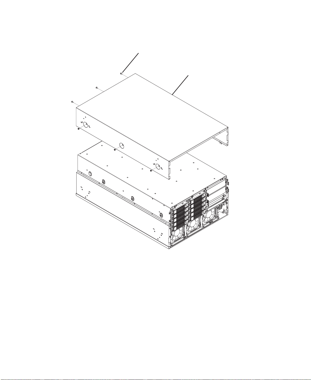
Opening the server case . . . . . . . . . . . . . . . . . . . . . . . . . . . . . . . . . . . . . . . . . . . . . . . . . . . 66
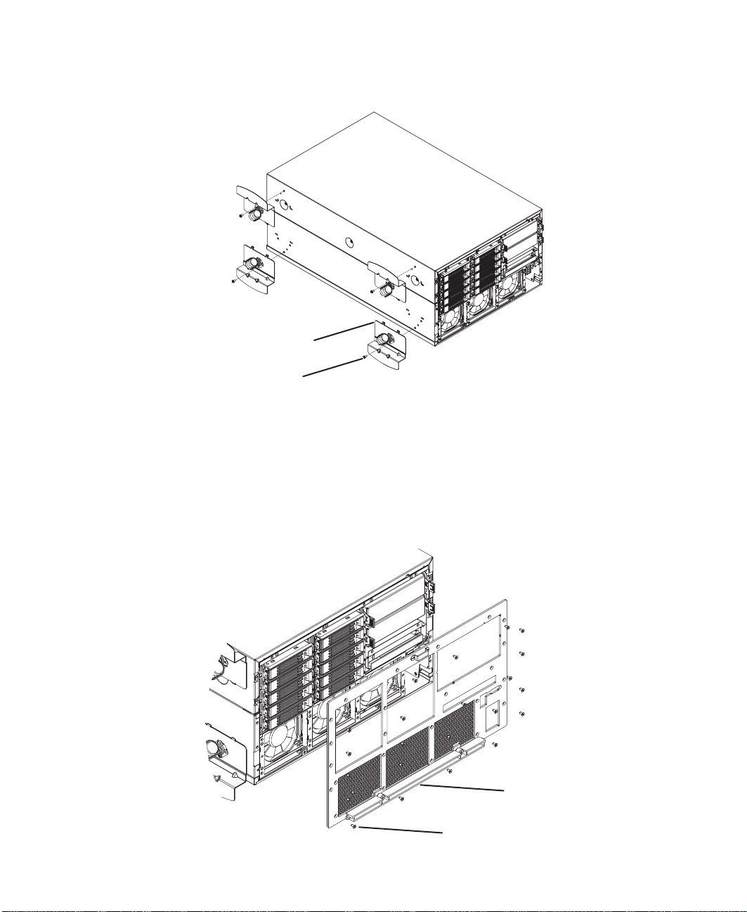
Removing and installing the processor air baffle . . . . . . . . . . . . . . . . . . . . . . . . . . . . . . . . . 67
Removing and installing the center brace . . . . . . . . . . . . . . . . . . . . . . . . . . . . . . . . . . . . . . 69
Closing the server case . . . . . . . . . . . . . . . . . . . . . . . . . . . . . . . . . . . . . . . . . . . . . . . . . . . . 72
Installing drives . . . . . . . . . . . . . . . . . . . . . . . . . . . . . . . . . . . . . . . . . . . . . . . . . . . . . . . . . . . 73
Installing and removing the CD or DVD drive . . . . . . . . . . . . . . . . . . . . . . . . . . . . . . . . 73
Installing a fixed, removable-media drive in a 5.25-inch drive bay . . . . . . . . . . . . . . . . 77
Installing a hot-swap hard drive . . . . . . . . . . . . . . . . . . . . . . . . . . . . . . . . . . . . . . . . . . . 80
Removing and installing the control panel . . . . . . . . . . . . . . . . . . . . . . . . . . . . . . . . . . . . . . 84
Memory . . . . . . . . . . . . . . . . . . . . . . . . . . . . . . . . . . . . . . . . . . . . . . . . . . . . . . . . . . . . . . . . . 85
Installing and removing memory boards . . . . . . . . . . . . . . . . . . . . . . . . . . . . . . . . . . . . 85
Installing and removing DIMMs . . . . . . . . . . . . . . . . . . . . . . . . . . . . . . . . . . . . . . . . . . 91
Configuring memory options . . . . . . . . . . . . . . . . . . . . . . . . . . . . . . . . . . . . . . . . . . . . . 95
PCI expansion cards . . . . . . . . . . . . . . . . . . . . . . . . . . . . . . . . . . . . . . . . . . . . . . . . . . . . . . 98
Hot installation or removal of PCI expansion cards . . . . . . . . . . . . . . . . . . . . . . . . . . . 99
Cold installation or removal of PCI expansion cards . . . . . . . . . . . . . . . . . . . . . . . . . 104
Fibre channel module . . . . . . . . . . . . . . . . . . . . . . . . . . . . . . . . . . . . . . . . . . . . . . . . . . . . . 106
Operating system driver installation and configuration . . . . . . . . . . . . . . . . . . . . . . . . 107
Fibre channel HBA manager software . . . . . . . . . . . . . . . . . . . . . . . . . . . . . . . . . . . . 108
Installing or removing the fibre channel module . . . . . . . . . . . . . . . . . . . . . . . . . . . . . 108
Processors . . . . . . . . . . . . . . . . . . . . . . . . . . . . . . . . . . . . . . . . . . . . . . . . . . . . . . . . . . . . . 111
Special handling of Intel Xeon processors . . . . . . . . . . . . . . . . . . . . . . . . . . . . . . . . . 111
Installation and removal of processors . . . . . . . . . . . . . . . . . . . . . . . . . . . . . . . . . . . . 111
Processor VRM requirements . . . . . . . . . . . . . . . . . . . . . . . . . . . . . . . . . . . . . . . . . . . 118
Installing an Intel Management Module (IMM) . . . . . . . . . . . . . . . . . . . . . . . . . . . . . . . . . 124
Installing and removing the ROMB (RAID on Motherboard) activation key and dedicated RAID
memory . . . . . . . . . . . . . . . . . . . . . . . . . . . . . . . . . . . . . . . . . . . . . . . . . . . . . . . . . . . . . . 126
Installing and removing the Smart Battery . . . . . . . . . . . . . . . . . . . . . . . . . . . . . . . . . 129
Power subsystem . . . . . . . . . . . . . . . . . . . . . . . . . . . . . . . . . . . . . . . . . . . . . . . . . . . . . . . . 133
Replacing a power supply module . . . . . . . . . . . . . . . . . . . . . . . . . . . . . . . . . . . . . . . 134
Replacing a power distribution board . . . . . . . . . . . . . . . . . . . . . . . . . . . . . . . . . . . . . 136
Replacing the SCSI hot-swap backplane . . . . . . . . . . . . . . . . . . . . . . . . . . . . . . . . . . . . . 139
Replacing the front panel I/O board . . . . . . . . . . . . . . . . . . . . . . . . . . . . . . . . . . . . . . . . . . 143
Replacing a hot-swap fan . . . . . . . . . . . . . . . . . . . . . . . . . . . . . . . . . . . . . . . . . . . . . . . . . 145
Replacing the CMOS battery . . . . . . . . . . . . . . . . . . . . . . . . . . . . . . . . . . . . . . . . . . . . . . . 147
Replacing the system board . . . . . . . . . . . . . . . . . . . . . . . . . . . . . . . . . . . . . . . . . . . . . . . 149
ii
www.gateway.com

5 Using the BIOS Setup Utility . . . . . . . . . . . . . . . . . . . . . . . . . . . . . . . . . . . . . . . . 153
Opening the BIOS Setup utility . . . . . . . . . . . . . . . . . . . . . . . . . . . . . . . . . . . . . . . . . . . . . 154
Updating the BIOS . . . . . . . . . . . . . . . . . . . . . . . . . . . . . . . . . . . . . . . . . . . . . . . . . . . . . . . 155
Rolling BIOS . . . . . . . . . . . . . . . . . . . . . . . . . . . . . . . . . . . . . . . . . . . . . . . . . . . . . . . . 155
Recovering the BIOS . . . . . . . . . . . . . . . . . . . . . . . . . . . . . . . . . . . . . . . . . . . . . . . . . . 156
Resetting the BIOS . . . . . . . . . . . . . . . . . . . . . . . . . . . . . . . . . . . . . . . . . . . . . . . . . . . 158
Resetting BIOS passwords . . . . . . . . . . . . . . . . . . . . . . . . . . . . . . . . . . . . . . . . . . . . . 161
6 Configuring your RAID solutions . . . . . . . . . . . . . . . . . . . . . . . . . . . . . . . . . . . . 163
Introduction . . . . . . . . . . . . . . . . . . . . . . . . . . . . . . . . . . . . . . . . . . . . . . . . . . . . . . . . . . . . . 164
Configuring your ROMB RAID solution with the RAID BIOS Console configuration utility 165
Configuring your ROMB RAID solution with the RAID Web Console . . . . . . . . . . . . . . . 174
Web Console components . . . . . . . . . . . . . . . . . . . . . . . . . . . . . . . . . . . . . . . . . . . . . 174
Client system requirements . . . . . . . . . . . . . . . . . . . . . . . . . . . . . . . . . . . . . . . . . . . . . 175
Quick configuration steps . . . . . . . . . . . . . . . . . . . . . . . . . . . . . . . . . . . . . . . . . . . . . . 175
Registration server . . . . . . . . . . . . . . . . . . . . . . . . . . . . . . . . . . . . . . . . . . . . . . . . . . . 176
Installing the Windows Web Console . . . . . . . . . . . . . . . . . . . . . . . . . . . . . . . . . . . . . 180
Launching the Web Console . . . . . . . . . . . . . . . . . . . . . . . . . . . . . . . . . . . . . . . . . . . . . . . 184
Configuring arrays and logical drives . . . . . . . . . . . . . . . . . . . . . . . . . . . . . . . . . . . . . 187
Reclaiming hot spare disks . . . . . . . . . . . . . . . . . . . . . . . . . . . . . . . . . . . . . . . . . . . . . 190
Reconfiguring existing arrays . . . . . . . . . . . . . . . . . . . . . . . . . . . . . . . . . . . . . . . . . . . 190
7 Troubleshooting . . . . . . . . . . . . . . . . . . . . . . . . . . . . . . . . . . . . . . . . . . . . . . . . . . . . . 193
Safety guidelines . . . . . . . . . . . . . . . . . . . . . . . . . . . . . . . . . . . . . . . . . . . . . . . . . . . . . . . . 194
Error messages . . . . . . . . . . . . . . . . . . . . . . . . . . . . . . . . . . . . . . . . . . . . . . . . . . . . . . . . . 195
Troubleshooting . . . . . . . . . . . . . . . . . . . . . . . . . . . . . . . . . . . . . . . . . . . . . . . . . . . . . . . . . 197
First steps . . . . . . . . . . . . . . . . . . . . . . . . . . . . . . . . . . . . . . . . . . . . . . . . . . . . . . . . . . 197
Battery replacement . . . . . . . . . . . . . . . . . . . . . . . . . . . . . . . . . . . . . . . . . . . . . . . . . . 197
Beep codes . . . . . . . . . . . . . . . . . . . . . . . . . . . . . . . . . . . . . . . . . . . . . . . . . . . . . . . . . . . . 199
Post error beep codes . . . . . . . . . . . . . . . . . . . . . . . . . . . . . . . . . . . . . . . . . . . . . . . . . 199
BIOS recovery beep codes . . . . . . . . . . . . . . . . . . . . . . . . . . . . . . . . . . . . . . . . . . . . . 199
Additional beep codes provided by Intel Management Modules . . . . . . . . . . . . . . . . 200
LED information . . . . . . . . . . . . . . . . . . . . . . . . . . . . . . . . . . . . . . . . . . . . . . . . . . . . . . . . . 201
Diagnostic POST LEDs . . . . . . . . . . . . . . . . . . . . . . . . . . . . . . . . . . . . . . . . . . . . . . . . 202
BIOS . . . . . . . . . . . . . . . . . . . . . . . . . . . . . . . . . . . . . . . . . . . . . . . . . . . . . . . . . . . . . . 214
CD or DVD drive . . . . . . . . . . . . . . . . . . . . . . . . . . . . . . . . . . . . . . . . . . . . . . . . . . . . . 214
Diskette drive . . . . . . . . . . . . . . . . . . . . . . . . . . . . . . . . . . . . . . . . . . . . . . . . . . . . . . . . 215
USB flash memory device . . . . . . . . . . . . . . . . . . . . . . . . . . . . . . . . . . . . . . . . . . . . . . 215
Expansion cards . . . . . . . . . . . . . . . . . . . . . . . . . . . . . . . . . . . . . . . . . . . . . . . . . . . . . 217
Hard drive . . . . . . . . . . . . . . . . . . . . . . . . . . . . . . . . . . . . . . . . . . . . . . . . . . . . . . . . . . 218
Internet . . . . . . . . . . . . . . . . . . . . . . . . . . . . . . . . . . . . . . . . . . . . . . . . . . . . . . . . . . . . . 219
Keyboard . . . . . . . . . . . . . . . . . . . . . . . . . . . . . . . . . . . . . . . . . . . . . . . . . . . . . . . . . . . 219
Memory . . . . . . . . . . . . . . . . . . . . . . . . . . . . . . . . . . . . . . . . . . . . . . . . . . . . . . . . . . . . 219
Monitor . . . . . . . . . . . . . . . . . . . . . . . . . . . . . . . . . . . . . . . . . . . . . . . . . . . . . . . . . . . . . 220
Power . . . . . . . . . . . . . . . . . . . . . . . . . . . . . . . . . . . . . . . . . . . . . . . . . . . . . . . . . . . . . . 220
www.gateway.com
iii

Processor . . . . . . . . . . . . . . . . . . . . . . . . . . . . . . . . . . . . . . . . . . . . . . . . . . . . . . . . . . . 221
Telephone support . . . . . . . . . . . . . . . . . . . . . . . . . . . . . . . . . . . . . . . . . . . . . . . . . . . . . . . 223
Before calling Gateway Customer Care . . . . . . . . . . . . . . . . . . . . . . . . . . . . . . . . . . . 223
Telephone support . . . . . . . . . . . . . . . . . . . . . . . . . . . . . . . . . . . . . . . . . . . . . . . . . . . . 224
Tutoring and training . . . . . . . . . . . . . . . . . . . . . . . . . . . . . . . . . . . . . . . . . . . . . . . . . . . . . 224
A Server Specifications . . . . . . . . . . . . . . . . . . . . . . . . . . . . . . . . . . . . . . . . . . . . . . . . 225
System specifications . . . . . . . . . . . . . . . . . . . . . . . . . . . . . . . . . . . . . . . . . . . . . . . . . . . . . 226
System board specifications . . . . . . . . . . . . . . . . . . . . . . . . . . . . . . . . . . . . . . . . . . . . . . . . 227
Fibre channel card specifications . . . . . . . . . . . . . . . . . . . . . . . . . . . . . . . . . . . . . . . . . . . . 229
Environmental specifications . . . . . . . . . . . . . . . . . . . . . . . . . . . . . . . . . . . . . . . . . . . . . . . 230
Electronic specifications . . . . . . . . . . . . . . . . . . . . . . . . . . . . . . . . . . . . . . . . . . . . . . . . . . . 231
Memory map . . . . . . . . . . . . . . . . . . . . . . . . . . . . . . . . . . . . . . . . . . . . . . . . . . . . . . . . 231
Interrupts . . . . . . . . . . . . . . . . . . . . . . . . . . . . . . . . . . . . . . . . . . . . . . . . . . . . . . . . . . . 231
Additional specifications . . . . . . . . . . . . . . . . . . . . . . . . . . . . . . . . . . . . . . . . . . . . . . . . . . . 233
B BIOS Settings . . . . . . . . . . . . . . . . . . . . . . . . . . . . . . . . . . . . . . . . . . . . . . . . . . . . . . . 235
C Field Replaceable Unit (FRU) Kits . . . . . . . . . . . . . . . . . . . . . . . . . . . . . . . . . . . 245
Available FRU kits . . . . . . . . . . . . . . . . . . . . . . . . . . . . . . . . . . . . . . . . . . . . . . . . . . . . . . . 246
D Extensible Firmware Interface (EFI) Shell . . . . . . . . . . . . . . . . . . . . . . . . . . . . 249
Introduction . . . . . . . . . . . . . . . . . . . . . . . . . . . . . . . . . . . . . . . . . . . . . . . . . . . . . . . . . . . . . 250
Basic EFI Shell commands . . . . . . . . . . . . . . . . . . . . . . . . . . . . . . . . . . . . . . . . . . . . . . . . 251
E Safety, Regulatory, and Legal Information . . . . . . . . . . . . . . . . . . . . . . . . . . . 255
Index . . . . . . . . . . . . . . . . . . . . . . . . . . . . . . . . . . . . . . . . . . . . . . . . . . . . . . . . . . . . . . . . . . . . 265
iv
www.gateway.com

Chapter 1
Checking Out Your Gateway
Server
• Locating drives, ports, jacks, and controls
• Locating system board components
• Getting help
1

Chapter 1: Checking Out Your Gateway Server
Front
Control
panel
USB ports
Video port
CD or
DVD
drive
5.25-inch
drive bays
(2)
Control panels
NIC 2 activity LED
NIC 1 activity LED
Hard drive
activity/fault
LED
Status LED
Hot swap
fans
(behind
faceplate)
Hot-swap
hard drive
bays (10)
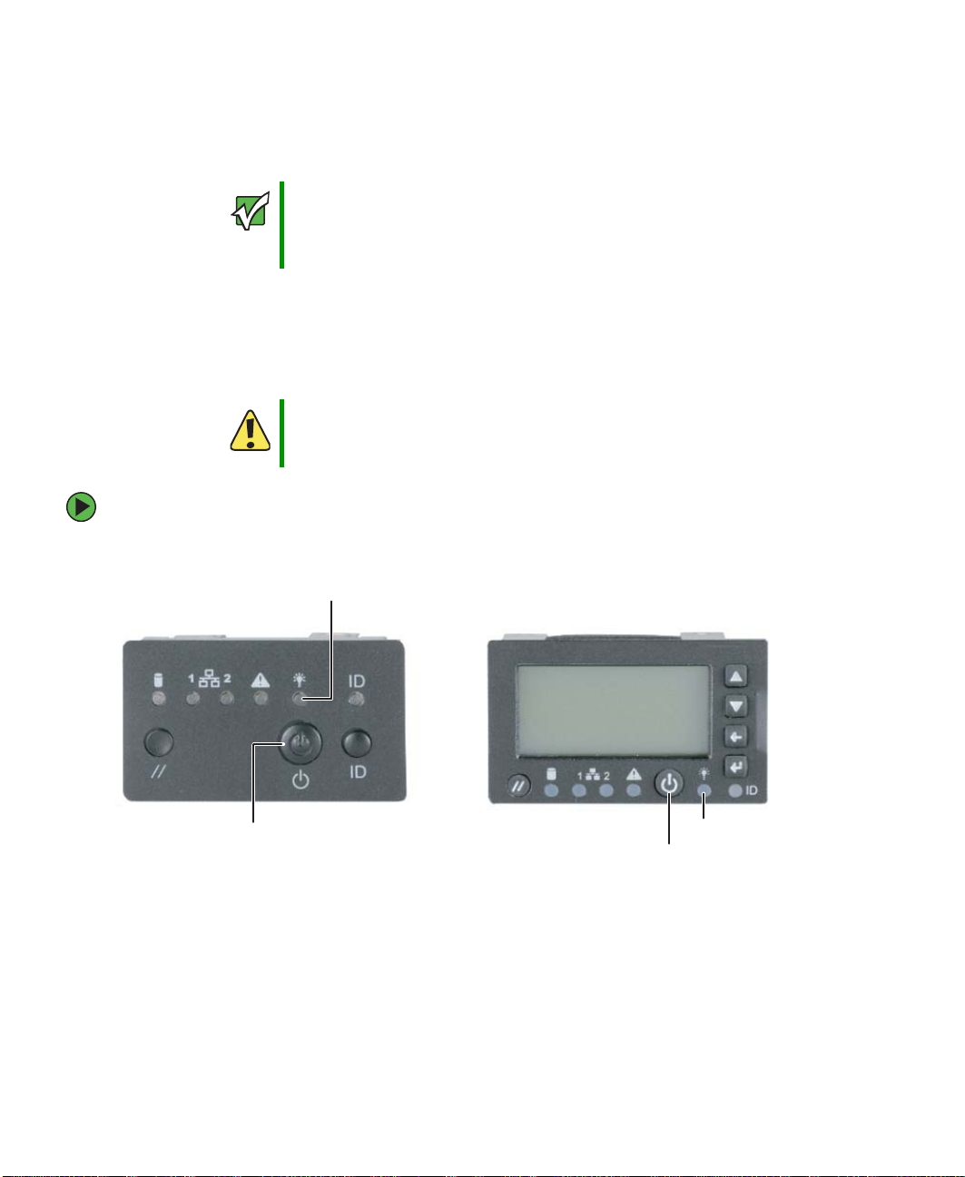
Power/sleep LED
ID LED
Scroll up
Scroll down
Back button
Select button
Reset button
Standard control panel Optional control panel
2
Power button
ID button
Reset
button
Combined hard drive
activity and fault LED
NIC 1 activity LED
NIC 2 activity LED
www.gateway.com
ID LED
Power/sleep LED
Power button
Status LED
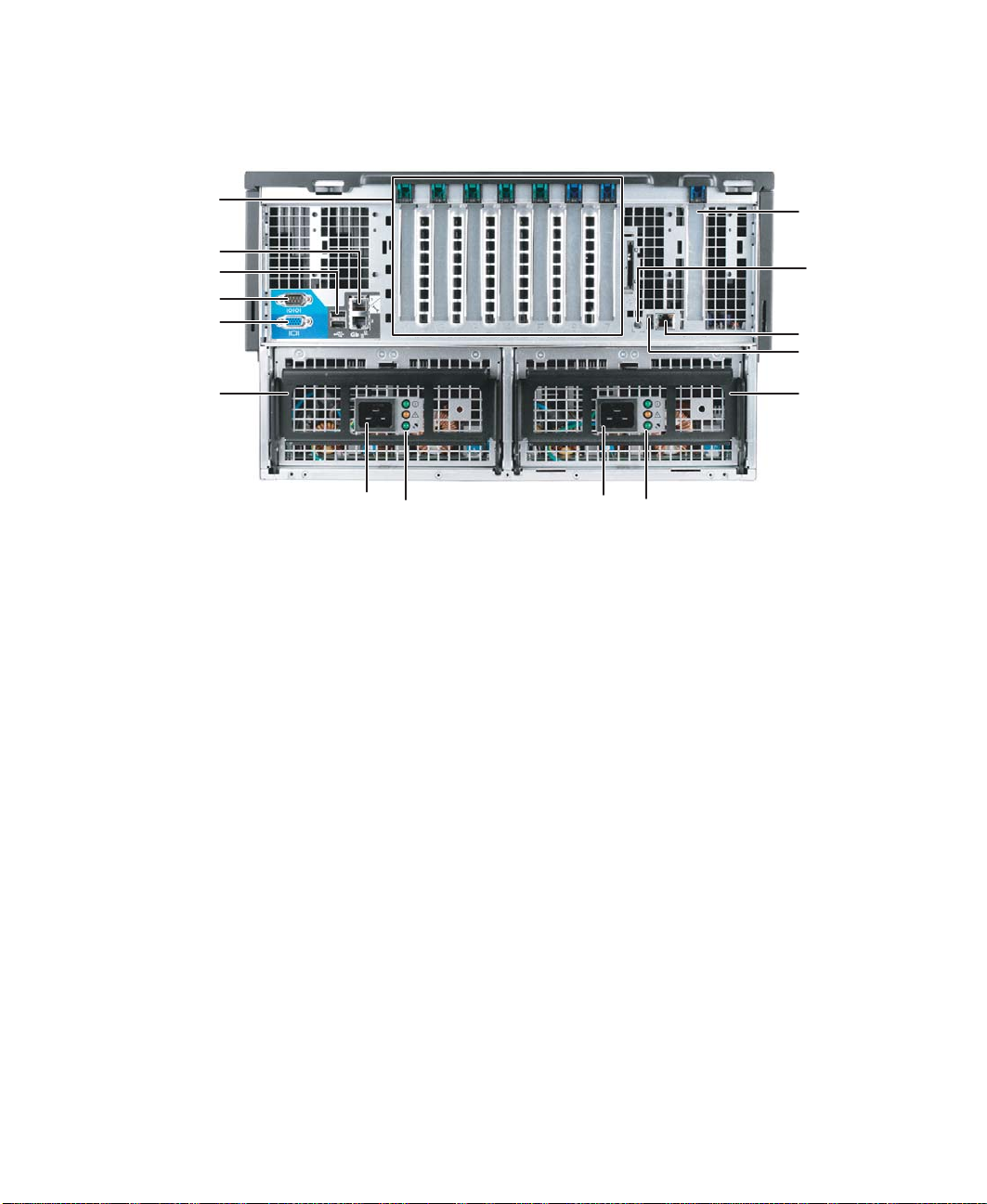
Back
PCI slots
(shown with
EMI shields)
Gb network
ports (2)
USB ports
Serial port
Monitor port
Power supply
module latch
Back
Fiber channel
module slot
(optional)
ID LED
RJ-45 Server
management
connector
ID button
Power suppl y
module latch
Power connector
Power supply
LEDs
Power
connector
Power suppl y LEDs
www.gateway.com
3
Chapter 1: Checking Out Your Gateway Server
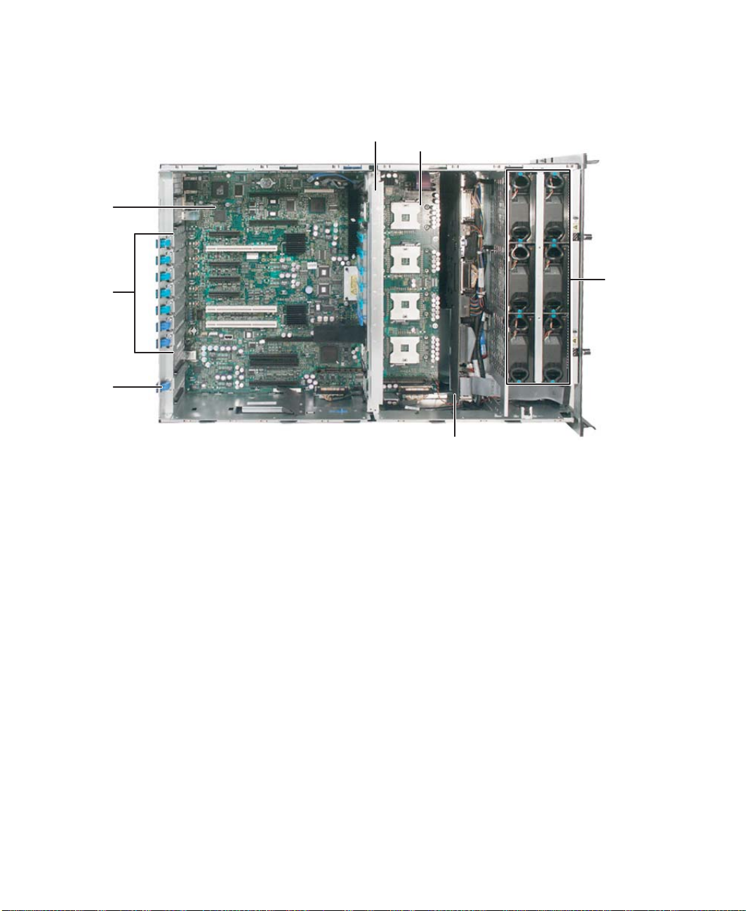
Interior
System
board
Card
retention
clips
Fiber
module
retention
clip
Center brace
CPU Sockets
Hot-swap
fans
Front
Hot-swap drive bay
backplane
4
www.gateway.com
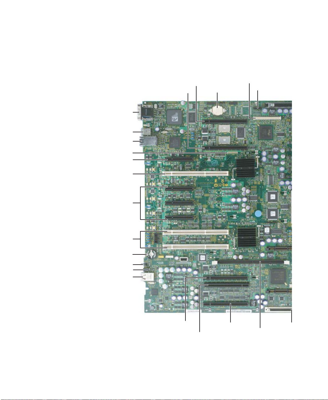
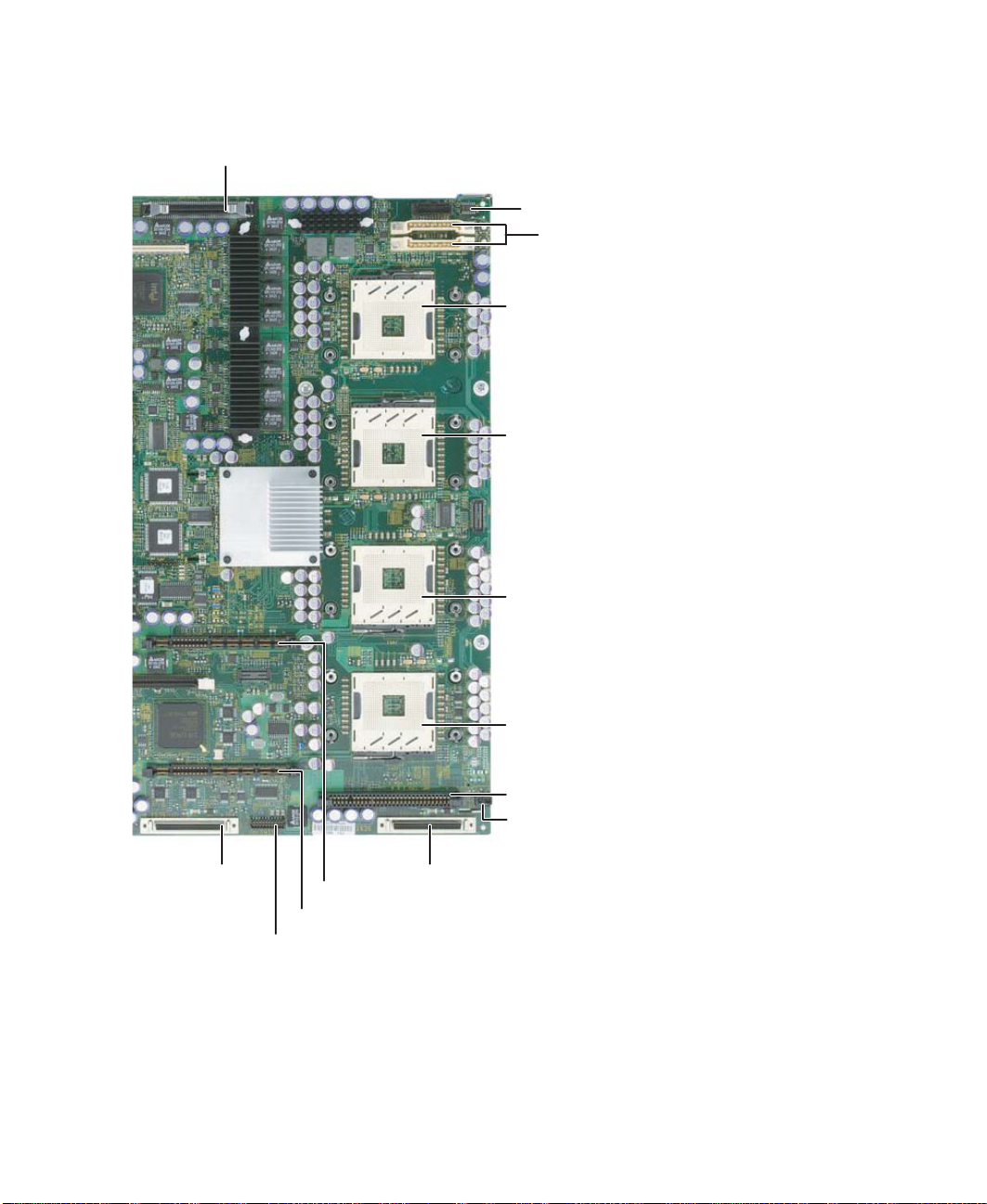
System board
IMM
Left side
Memory board B connector
Memory board A connector
CMOS
battery
System board
module
connector
SATA connector
Serial/video
connectors
USB 1 and 2 connectors
NIC 1 and NIC 2 connectors
Diagnostic LEDS (8)
PCI slot 1 Hot plug Express x8
PCI slot 2 Hot plug PCI-X 133
PCI slots 3, 4, and 5
Hot plug Express x4
PCI slots 6 and 7 PCI-X 100
(non-hot plug)
ROMB RAID activation key
ID button
ID LED
RJ-45 Server management port
Memory board C connector
Fibre channel module connector
www.gateway.com
Memory board D
connector
Onboard RAID
Cache Memory
connector
5
Chapter 1: Checking Out Your Gateway Server
t
Right side
Front panel connector
Power distribution board signal connec
DC power connectors
CPU 1 socket
CPU 2 socket
SCSI channel B
connector
CPU 4 socket
CPU 3 socket
VRM 9.1 connector (processor cache)
Chassis intrusion connector
SCSI channel A connector
VRM 10.2L connector
VRM 10.2LD connector
RAID smart battery connector
6
www.gateway.com

Getting Help
Getting Help
In addition to your operating system’s documentation, you can use the following
information resources to help you use your server.
System Companion CD
Use the System Companion CD to access file utilities, Windows 2003 Server drivers, and
documentation for your server and its components. For more information, see Using Your
System Companion CD.
Gateway Web site
Gateway provides a variety of information on its Web site to help you use your server.
Visit the Gateway Web site at support.gateway.com for:
■ Technical documentation and product guides
■ Technical tips and support
■ Updated hardware drivers
■ Order status
■ Frequently asked questions (FAQs)
www.gateway.com
7

Chapter 1: Checking Out Your Gateway Server
8
www.gateway.com

Chapter 2
Setting Up Your Server
• Setting up the hardware
• Protecting from power source problems
• Mounting your server into a cabinet
• Starting and turning off your server
• Setting up the operating system
• Configuring SCSI features
9

Chapter 2: Setting Up Your Server
Setting up the hardware
To make sure that your working environment is safe:
■ Use a clean, dry, flat, stable surface for your server. Allow at least 6 inches at the back
of the server for cabling and air circulation.
■ Use the instructions on your server’s setup poster to set up your hardware.
■ Use an uninterruptible power supply (UPS) with surge protection for protection from
power outages and power spikes.
Warni ng
■ Avoid subjecting your server to extreme temperature changes. Do not expose your
Your server comes with a 3-wire AC power cords fitted with the correct
plug style for your region. If these plugs do not match the connector
on your UPS or wall outlet, do not attempt to modify the plugs in any
way. Use a UPS or wall outlet that is appropriate for the supplied
AC power cords.
server to direct sunlight, heating ducts, or other heat-generating objects. Damage
caused by extreme temperatures is not covered by your warranty. As a general rule,
your server is safest at temperatures that are comfortable for you.
■ Keep your server and magnetic media away from equipment that generates magnetic
fields, such as unshielded stereo speakers. Strong magnetic fields can erase data on
both diskettes and hard drives. Even a telephone placed too close to the server may
cause interference.
Mounting your server into a cabinet
The cabinet mounting hardware included with your server should be used with standard
4-post cabinets that have front and back vertical posts. If your cabinet is a different type,
obtain mounting hardware from the cabinet manufacturer.
Refer to the documentation that comes with the rackmount rail kit for installation
instructions.
10
Warni ng
Caution
Caution
Lifting the server and attaching it to the rack is a two-person job. If
needed, use an appropriate lifting device. A fully loaded Gateway
9715 server weighs about 130 lbs (60 kg).
Before attaching cabinet accessories, make sure that the server is
turned off and all power cords are unplugged.
The cabinet must provide sufficient airflow to the front of the server
to maintain correct cooling.
www.gateway.com

Setting up the hardware
Converting to pedestal configuration
To convert your server to a pedestal configuration, you need a pedestal conversion kit. To
order the conversion kit, contact Gateway Customer Care, Gateway Sales, or visit
accessories.gateway.com
“Telephone support” on page 223.
Contents of the conversion kit
The pedestal conversion kit contains the following:
■ Outer cover (1)
■ Phillips screws (6)
■ Caster assemblies (4)
■ Pedestal face plate (1)
■ Torx screws (6)
Tools required
You need the following tools to convert to the pedestal configuration:
■ Phillips head screwdriver (#2)
. For more information on contacting Customer Care, see
■ Torx screwdriver
To convert your server to the pedestal configuration:
1 Follow the instructions in “Preventing static electricity discharge” on page 65.
Warni ng
Lifting the server or removing it from the rack is a two-person job. If
needed, use an appropriate lifting device. A fully loaded Gateway
9715 server weighs about 130 lbs (60 kg).
2 Remove the server from the rack cabinet, if necessary.
3 Remove the slide rails and cable management arm (if installed).
4 Remove the optional control panel (if installed), by following the instructions in
“Removing and installing the control panel” on page 84.
www.gateway.com
11
Chapter 2: Setting Up Your Server
5 Turn the server over so the bottom is facing up, then position the outer cover, supplied
with the conversion kit, on the bottom of the chassis.
Screw
Outer cover
6 Align the screw holes in the outer cover with the holes in the chassis and secure with
the six screws provided with the kit.
12
www.gateway.com
Setting up the hardware
7 Align each of the casters with its screw hole on the (new) bottom of the server and
secure with one Phillips screw per caster (provided with caster assembly).
Caster
Screw
8 Remove the Torx screws securing the rack faceplate to the front of the chassis, then
remove the faceplate.
9 Align the screw holes in the pedestal faceplate with the holes on the front of the
chassis, then secure with the Torx screws you previously removed.
Insert and partially tighten four screws before inserting the remaining screws, then
fully tighten the screws.
Faceplate
Torx Screw
www.gateway.com
13

Chapter 2: Setting Up Your Server
10 Reinstall the optional control panel by following the instructions in “Removing and
installing the control panel” on page 84.
11 Set the server upright on its casters and reconnect the data and power cables.
14
www.gateway.com

Protecting from power source problems
Protecting from power source problems
Surge protectors, line conditioners, and uninterruptible power supplies can help protect
your server against power source problems.
Surge protectors
During a power surge, the voltage level of electricity coming into your server can increase
to far above normal levels and cause data loss or server damage. Protect your server and
peripheral devices by connecting them to a surge protector, which absorbs voltage surges
and prevents them from reaching your server.
Caution
When you purchase a surge protector:
■ Make sure that the surge protector meets the appropriate product safety certification
for your location, such as Underwriters Laboratories (UL).
■ Check the maximum amount of voltage the protector allows to pass through the line.
The lower the voltage, the better the protection for your server.
■ Check the energy absorption (dissipation) rating. The higher the energy absorption
rating, the better the protection for your server.
High voltages can enter your server through the power cord, and the
modem and network connections. Protect your server by using a
surge protector. If you have a modem, use a surge protector that has
the appropriate type of modem jack. During an electrical storm,
unplug the surge protector and the modem and network cables.
Line conditioners
A line conditioner protects your server from the small fluctuations in voltage from an
electrical supply. Most servers can handle this variation, called line noise, without problems.
However, some electrical sources include more line noise than normal. Line noise can also
be a problem if your server is located near, or shares a circuit with, a device that causes
electromagnetic interference, such as a television or a motor.
Some surge protectors and uninterruptible power supplies include simple line-conditioning
capabilities.
Uninterruptible power supplies
Use an uninterruptible power supply (UPS) to protect your server from data loss during a
total power failure. A UPS uses a battery to keep your server running temporarily during
a power failure and lets you save your work and shut down your server. You cannot run
your server for an extended period of time while using only the UPS. To buy a UPS, visit
accessories.gateway.com
.
www.gateway.com
15
Chapter 2: Setting Up Your Server
Starting your server
Before you start your server for the first time:
Important
■ Make sure that the server and monitor are plugged into a power outlet or UPS and
When you plug the AC power cords into the power supplies, wait for
20 to 30 seconds. The system will automatically power on for about
3 seconds, then power down. This allows the BMC to initialize the
out-of-band management capabilities.
that the UPS (if you are using one) is turned on.
■ Make sure that all cables are connected securely to the correct ports and jacks on the
back of the server.
Caution
When you connect peripheral devices to the server, make sure that
your server and devices are turned off and the power cords are
unplugged.
To start the server:
■ Press the power button.
Power/sleep LED
16
Power button
Power button
Power/sleep LED
Standard control panel Optional control panel
www.gateway.com
When the power/sleep LED is... It means...
Green The server is turned on.
Off The server is turned off (if ACPI is off).
Slowly blinking Low power state — S1 (if ACPI is on).
Off Low power state — S4/S5 (if ACPI is on).
Starting your server
Important
During the POST sequence, it takes from 3 to 10 minutes to see the
first screen. This is normal and does not indicate an error or problem.
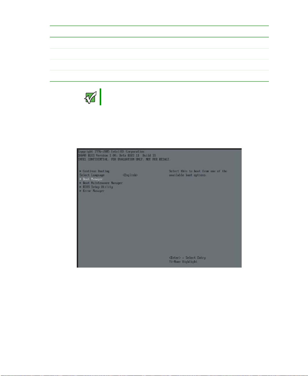
Normally, the server fans start and the POST begins running (you can follow the boot
progress on the monitor). The SCSI BIOS scan is displayed, followed by the Gateway
logo screen. The Gateway logo screen contains the BIOS version and copyright
information. Press any key to access the System Options menu.
The System Options menu contains the following options. Press the up and down
arrow keys to highlight your selection, then press E
■ Continue Booting - Selected by default (will occur automatically, after a pre-set time
NTER to select:
period.
■ Boot Manager - Lets you select from one of the available boot options. The server
will attempt boot from the first device on the list. If the first device is not available,
it will continue down the list until it reaches an available device. To modify these
Boot Options, select the Boot Maintenance Manager (described below).
www.gateway.com
17
Chapter 2: Setting Up Your Server
■ Boot Maintenance Manager - A menu of choices that lets you configure boot options
and boot environment variables.
■ BIOS Setup Utility - Lets you configure the server BIOS settings.
■ POST Error Manager - Lets you view POST errors detected by the system.
If nothing happens when you press the power button:
■ If your server is plugged into a UPS, make sure that the UPS is connected securely
to an electrical outlet, turned on, and working correctly.
■ Make sure that the monitor is connected to the server, plugged into the power
outlet or UPS, and turned on. You may also need to adjust the monitor’s brightness
and contrast controls.
Important
The first time you turn on the server, any pre-installed operating
system may begin asking you for configuration settings. See your
operating system’s documentation for instructions on configuring
advanced settings for your specific network.
Selecting the boot device
To select which device your server boots from:
1 During server startup, press any key to access the System Options Menu.
2 Press the up and down arrow keys to select Boot Manager from the System Options
Menu, then press E
NTER. The Boot menu opens.
18
www.gateway.com

Starting your server
3 Press the up and down arrow keys to select the device you want to boot from, then
press E
■ Removable Dev. (Removable device)
■ ATAPI CDROM (CD or DVD drive)
■ Hard Drive
■ IBA GE NIC (Network boot)
NTER. Common choices include:
Understanding the power-on self-test
When you turn on your server, the power-on self-test (POST) routine checks the server
memory and components. If POST finds any problems, the server displays error messages.
Write down any error messages that you see, then see “Error messages” on page 195 and
“Post error beep codes” on page 199 for troubleshooting information.
www.gateway.com
19

Chapter 2: Setting Up Your Server
Controlling your server
Local control
Your server can be controlled locally by installing a USB keyboard and a USB mouse. There
are USB connectors, as well as video connectors, on both the front and back of the server.
There are no PS/2 connectors on this server.
Remote control
The BIOS supports redirection of both video and keyboard through a serial link (COM port)
on this server. When console redirection is enabled, local (host server) keyboard input and
video output are passed both to the local keyboard and video connections and to the
remote console through the serial link. Keyboard inputs from both sources are considered
valid and video is displayed to both outputs.
With console redirection, you can control the server without a host keyboard or monitor
attached to the server, and you can run the server entirely by remote control, including
setup and other text-based utilities.
Serial configuration settings
When redirecting through a modem (instead of a null modem cable), the modem needs
to be configured as follows:
■ Auto-answer (for example, ATS0=2, to answer after two rings).
■ Modem reaction to DTR set to return to command state (for example, AT&D1) - failure
to provide this setting results in the modem either dropping the link when the server
reboots (as in AD&D0) or becoming unresponsive to server baud rate changes (as in
AT&D2).
■ Handshake must be set to CTS/RTS + CD for optimum performance - If EMP is sharing
the COM port with serial redirection, the handshaking must be set to Xon/Xoff + CD.
An EMP option utilizing CD should not be used if a modem is not used and the CD
is not connected.
■ Both EMP and console redirection require N, 8, 1 mode (no parity, 8-bit dta, 1 stop bit).
The BIOS does not require that the splash logo be turned off for console redirection to
function. The BIOS supports multiple consoles, some of which are in graphics mode and
some in text mode. The graphics consoles can display the logo while the text consoles
receive the redirected text.
Console redirection ends at the beginning of the Legacy OS boot (INT 19h).
20
www.gateway.com

Controlling your server
Keystroke mappings
During console redirection, the remote terminal (which may be a dumb terminal or a
system with a modem running a communication program) sends keystrokes to the local
server. The local server passes video back over this same link. The keystroke mappings
follow VT-UTF8 format with the following extensions.
Setting up alias keys
The DEL and CTRL + (function key) combinations are synonyms for the F2 or Setup key.
These are not prompted for in screen messages. These hotkeys are defined only for console
redirection support and are not used on locally attached keyboards.
Standalone ESC key for headless operation
To complete an escape sequence, the timeout must be two seconds for entering additional
characters following an escape.
■ ESC followed by a two-second pause is interpreted as a single escape.
■ ESC followed within two seconds by one or more characters that are not forming a
sequence described in this document are interpreted as E
characters, not an escape sequence.
All of the escape sequences in the following table are input sequences, that is, they are
sent to the BIOS from the remote terminal.
SC + the character, or
Escape Sequence Description
E
SC + R + ESC + R + ESC + R
This will implement but will default to “disabled.”
REmote console reset
ESC + ( BMC Mux switch escape sequence
ESC + CDZi + (terminal-type-number) Dynamic Terminal Type choice, where:
0 = PC-ANSI (the only current terminal type)
1 = VT100 (not implemented, but honored as VT100+)
2 = VT100+
3 = VT-UTF8
ESC + CDZ0 Inhibit console redirection
ESC + CDZ1 Restart console redirection
ESC + CDZ2 “Soft” inhibit console redirection, without serial port or
modem reset.
www.gateway.com
21

Chapter 2: Setting Up Your Server
Limitations
The BIOS console redirection terminates after an EFI-aware operating system calls EFI Boot
Service ExitBootServices. The operating system is responsible for continuing the console
redirection after that point. BIOS console redirection is a text console and any graphical
data, such as a logo, is not redirected.
Interface to server management
If the BIOS determines that console redirection is enabled, it passes the baud rate through
the IPMB (Intelligent Platform Management Bus) to the appropriate management controller.
Example setup for console redirection
The following is an example of how to configure the console/host and server for console
redirection. In this example, the console is running under Windows. The console and
server are directly connected through the serial ports of both systems using a serial null
modem cable.
To redirect the server console:
1 Turn on the server.
2 Press the up and down arrow keys to select BIOS Setup from the System Options Menu,
then press E
NTER. The BIOS setup utility menu opens.
3 Press the up and down arrow keys to select Server Management menu, then press ENTER.
The Server Management menu opens.
4 Press the up and down arrow keys to select Console Redirection, then select COM1
Console Redirection
.
5 Make the following settings:
■ Set Console Redirect to Enabled
■ Set Connection Type to Direct
■ Set Baud Rate to 115.2K
■ Set the Flow Control to CTS/RTS
■ Set the Terminal Type to VT-UTF8
6 Press F10, then select Yes to save the changes and exit the BIOS Setup utility.
7 Press ENTER to confirm. The server reboots and console redirection is enabled.
8 Turn off the server and configure the console.
22
www.gateway.com

Controlling your server
To configure the console:
1 Turn on the console system and let the operating system start.
2 Click Start, All Programs, Accessories, Communications, then click Hyperterminal.
3 When the Connection Description window opens, enter Guest in the Name field, then
click
OK.
4 When the Connect To window opens, click the COM port of the console to which the
null modem cable is connected (for example, COM1).
5 When the COM1 Properties window opens, make the following settings:
■ Bits per second to 115200
■ Flow control to Hardware (CTS/RTS)
■ Leave the other settings at their default values
6 Click OK to accept the settings and enter the hyperterminal screen.
7 Turn on the server. The console starts displaying the redirection after the video on
the server synchronizes.
www.gateway.com
23

Chapter 2: Setting Up Your Server
Turning off your server
Every time you turn off your server, first shut down the operating system. You may lose
data if you do not follow the correct procedure.
To turn off the server:
1 See the operating system’s documentation or online help for instructions on shutting
down the operating system. Whenever possible, you should use the operating system’s
shut down procedure instead of pressing the power button.
2 If your server did not turn off automatically, press and hold the power button until
the server turns off.
Warni ng
Caution
The power button on the server does not turn off server AC power.
To remove AC power from the server, you must unplug both
AC power cords from the wall outlet or power source. The power
cords are considered the disconnect device to the main (AC) power.
If you routinely turn off your server (daily or weekly), do not unplug
the server or use the On/Off switch on the UPS. Regularly cutting
off all power to your server may cause the CMOS battery to fail
prematurely.
24
www.gateway.com

Setting up the operating system
Setting up the operating system
If you ordered your server with the operating system already installed by Gateway, in most
cases it is completely installed and the basic settings are already configured. The Windows
Small Business Server operating system may require additional installation, depending on
the version you ordered. See your operating system’s documentation for instructions on
completing the installation or configuring advanced settings for your specific network.
If you are installing an operating system because it was not already installed by Gateway,
see the appropriate installation guide for instructions.
www.gateway.com
25

Chapter 2: Setting Up Your Server
Initial hardware settings
Your server comes from the manufacturer with the correct initial hardware settings to
operate your server as configured. However, at some point you might want to change
settings to reflect a tasking change, a change in security requirements, or the addition of
new resources to your server.
General hardware settings, as well as the onboard LSI RAID solution, can be changed by
using the BIOS Setup utility, and advanced RAID settings for the Intel ROMB RAID solution
can be changed by using the RAID BIOS Console or Web Console (or the specific RAID
console which accompanied a customized, add-in RAID solution).
For information on the BIOS Setup utility, see “Using the BIOS Setup Utility” on page 153.
For information on BIOS settings, see “BIOS Settings” on page 235. For information on
the RAID BIOS Console utility, see “Configuring your RAID solutions” on page 163. For
information on a specific RAID console for an add-in RAID solution, see the documentation
on that hardware which accompanied your server.
26
www.gateway.com

Configuring SCSI features
Configuring SCSI features
The LSI Logic MPT SCSI Setup Utility lets you configure your server’s SCSI features. For
information on configuring your RAID solutions, see “Configuring your RAID solutions”
on page 163.
To access the LSI Logic MPT SCSI Setup Utility:
1 Press CTRL + C during POST, right after the memory test but prior to entering the
System Options menu. The LSI Logic MPT SCSI Setup Utility main menu screen opens.
2 Press F2 to access the menu bar at the top of the screen, then press the HOME and
E
ND keys to select either the Boot Adapter List or Global Properties.
To access and change the Boot Adapter List:
1 Follow the instructions in “To access the LSI Logic MPT SCSI Setup Utility:” on page 27.
www.gateway.com
27

Chapter 2: Setting Up Your Server
2 Press F2 to access the menu bar at the top of the screen, then press the HOME and
E
ND keys to select the Boot Adapter List. The Boot Adapter List screen opens.
This list lets you add or remove boot adapters by highlighting the boot adapter and
pressing the + or - key to change the status.
3 If you do not want to make any changes, press ESC to exit the utility.
- OR -
When you are finished adding or removing boot adapters, press E
screen will open.
28
www.gateway.com
NTER, The Exit menu

Configuring SCSI features
4 Use the up and down arrow keys to select one of the following options:
■ Cancel Exit - To cancel the exit and return to the adapter or device properties screen.
■ Save Changes then exit this menu - To save your changes and exit the menu.
■ Discard changes then exit this menu - To discard your changes and exit the menu.
■ Exit the Configuration Utility - To exit the utility entirely.
If you made changes, the system will reboot when you exit the utility.
To access and change the Global Properties List:
1 Follow the instructions in “To access the LSI Logic MPT SCSI Setup Utility:” on page 27.
2 Press F2 to access the menu bar at the top of the screen, then press the HOME and
E
ND keys to select the Global Properties List. The Global Properties List screen opens.
3 Use the up and down arrow keys to select options from the list and +/- to change
the settings:
■ Pause when boot alert displayed (Ye s or No)
■ Boot information display mode (Verbose or Ter se)
■ Negotiate with Devices (Supported or All)
■ Video Mode (Color or Monochrome)
www.gateway.com
29

Chapter 2: Setting Up Your Server
■ Disable Integrated RAID (No or Yes)
■ Support Interrupt (Hook Interrupt (default) or Bypass Interrupt Hook)
■ <Restore Defaults> (to restore the default configuration of the adapters)
4 Press ESC to discard your changes and exit.
- OR -
When you are finished making changes, press E
NTER, The Exit menu screen will open.
5 Use the up and down arrow keys to select one of the following options:
■ Cancel Exit - To cancel the exit and return to the adapter or device properties screen.
■ Save Changes then exit this menu - To save your changes and exit the menu.
30
■ Discard changes then exit this menu - To discard your changes and exit the menu.
■ Exit the Configuration Utility - To exit the utility entirely.
If you made changes, the system will reboot when you exit the utility.
www.gateway.com

Configuring SCSI features
To access and change the Adapter Properties List:
1 Follow the instructions in “To access the LSI Logic MPT SCSI Setup Utility:” on page 27.
2 Use the up and down arrow keys to highlight the adapter to be configured, then press
E
NTER. The following message will be displayed:
Scanning for devices...
Important
If the RAID on MotherBoard (ROMB) feature is not enabled, the
following message will be displayed:
Current firmware does not support IME RAID type. Press any
key to continue.
When the utility is finished scanning for devices, the Adapter Properties screen opens.
3 Use the up and down arrow keys to select options from the list and +/- to change
the settings:
■ <Device Properties> Takes you to the Device Properties screen
■ Host SCSI ID (0 to 15)
■ SCSI Bus Scan Order (Low to High (0 - Max) or High to Low (Max - 0))
■ Removable Media Support (None, Boot Drive Only, or With Media Installed)
■ CHS (Cylinder Head Sector) Mapping (SCSI Plug and Play Mapping or Alternate CHS
Mapping
■ Spinup Delay (Secs) (1 to 15)
)
www.gateway.com
31

Chapter 2: Setting Up Your Server
■ Secondary Cluster Server (No or Ye s)
■ Termination Control (Auto)
■ <Restore Defaults> (to discard the changes and restore the default configuration
of the adapters)
4 If you selected anything but <Device Properties>, go to Step 6.
- OR -
If you selected <Device Properties>, press E
Important
The Device Properties screen is large and requires the use of the
arrow keys (or scroll bars) to scroll left and to scroll down to see all
of the configuration options.
NTER. The Device Properties screen opens.
5 Use the up and down arrow keys to select options from the list and +/- to change
the settings:
■ MB/Sec (320)
■ MT/Sec (0 or 5, 10, 20, 40, 80, 160)
■ Data Width (16 or 8)
■ Scan ID (Yes or No)
■ Scan Luns >0 (Yes or No)
32
www.gateway.com

Configuring SCSI features
■ Disconnect (On or Off)
■ SCSI Timeout (<10>)
■ Queue Tags (On or Off)
■ <Restore Defaults> (to discard the changes and restore the default configuration)
6 Press ESC to discard your changes and exit.
- OR -
When you are finished making changes, press E
NTER, The Exit menu screen will open.
7 Use the up and down arrow keys to select one of the following options:
■ Cancel Exit - To cancel the exit and return to the adapter or device properties screen.
■ Save Changes then exit this menu - To save your changes and exit the menu.
■ Discard changes then exit this menu - To discard your changes and exit the menu.
■ Exit the Configuration Utility - To exit the utility entirely.
If you made changes, the system will reboot when you exit the utility.
www.gateway.com
33

Chapter 2: Setting Up Your Server
34
www.gateway.com

Chapter 3
Managing and Maintaining
Your Server
• Managing your server and network
• Preparing for system recovery
• Caring for your server
35

Chapter 3: Managing and Maintaining Your Server
System administration
Gateway Server Manager
Gateway Server Manager lets you manage multiple computers on a Windows network from
a single window, then implement commands and policies across the network with a single
action. With Gateway Server Manager, you can run system management tasks which are
triggered by certain events or conditions.
Printed documentation comes with the Gateway Server Manager CD. You can find additional
documentation in the program’s online help.
Local control panel
This optional feature provides an intelligent front panel for your server and lets you
configure the server, monitor system status, and control the server from the panel. The
LCD panel has its own microcontroller and is independent of the operating system. Its
4×20 display provides information directly from the Baseboard Management Controller
(BMC) using the IPMB bus.
Interactions
The local control panel can:
■ Poll the BMC to determine alert conditions
■ Query the BMC for system event log entries
■ Display and control the power state of the server
■ Query the BMC for field replaceable units (FRUs)
■ Read BMC sensors
■ Retrieve BIOS POST progress codes
■ Issue IPMI commands to the BMC
■ Obtain BIOS-specific information from the BMC
In addition to the above, system software can also interact with the LCP to:
■ Write characters to the LCP
■ Read characters from the LCP
■ Read the state of the LCP buttons
■ Control the LCP buttons
■ Change LCP menus
36
www.gateway.com

■ Read information from the LCP microcontroller
■ Update the LCP firmware
Navigation
Scroll up button - one item up
Scroll down button - one item down
Back button
Select button
The following table shows the LCP menu options:
Menu Options Description
System administration
Configure the
server
Network (LAN channel 1 to 3)
■
IP address (BMC)
■
Netmask
■
Gateway address
■
Enable LAN channel
Inventory
■
CPUs
■
DIMMs
■
Drives
■
Power suppl ies
■
System fans
www.gateway.com
Configure TCO NIC
View system inventory
37

Chapter 3: Managing and Maintaining Your Server
Menu Options Description
Server name View server name
Asset tab information View asset tag
Server GUID View server GUID
BIOS revision View BIOS revision
BMC firmware revision View BMC firmware revision
Local Control Panel firmware revision View LCP firmware revision
HSC firmware revision View HSC firmware revision
HSC2 firmware revision View HSC2 firmware revision
Monitor the
server
POST progress codes View POST progress codes
Server health (drill down to subsystem(s)
View the health of the system
at fault)
System event log View the system event log
CPU sensors (CPU 1 to n)
■
Presence
■
Over temperature
■
On/off line
Chassis status
View CPU related status
View chassis related status
Intrusion status
Power suppl y 1 to n
■
Presence
■
Status
Fan 1 t o n
■
Presence
■
Status
■
Speed
HSC 1 to 2
■
Presence
■
Status
Temperatures (all available temperature
View all available temperature sensor status
sensors
38
www.gateway.com

Menu Options Description
System administration
Control the
server
Boot flags (select from available boot
flags)
■
Set the flag — one time reboot
■
Reboot the system
Power control
■
Power on
■
Power off (graceful or hard)
Reset Power control
IPMI control
■
Power on
■
Power off (graceful or hard)
IPMI command screen
■
Issue an IPMI command (text or hex)
Set up the server Language selection (display loaded
language files)
Status setup
■
Interval timing (set time to retrieve
status)
■
Subsystem mask (mask off
subsystems)
Configure boot order
Power control
Control the power state by creating button
pushes — as if performed on the front panel
by the user.
IPMI control
Send the chipset a power control command.
The same functionality as if done over LAN
or by GSM.
Issue an IPMI command
Select the LCP display language
Set sensor refresh interval
Password setup
■
Password exists/does not exist
■
Create/change password
Remote access rights
■
View (grant or deny)
■
Write (grant or deny)
■
Buttons (grant or deny)
Password setup
Remote access control
Server security
To prevent unauthorized use of the server, you can set BIOS startup passwords.
Using BIOS security passwords
Set up a supervisor password to prevent unauthorized access to the BIOS Setup utility. After
you create a supervisor password, you can set up a user password to prevent unauthorized
access to the server.
www.gateway.com
39

Chapter 3: Managing and Maintaining Your Server
You c a n:
■ Enter either password to finish starting the server.
■ Enter the supervisor password to access the BIOS Setup utility.
For information about resetting BIOS passwords, see “Resetting BIOS passwords” on
page 161.
To set the BIOS security passwords:
1 Restart your server, then press any key when the Gateway logo screen appears during
startup. The System Options menu opens.
2 Select BIOS Setup utility, then press ENTER. The BIOS Setup utility opens.
3 Select the Security menu.
4 Select the password to set according to the following table.
Option Description
Supervisor password To control access to system configuration, set a
supervisor password. Using a supervisor password lets
you make changes to any setting in the BIOS.
Passwords can be cleared. To clear the passwords, see
“Resetting BIOS passwords” on page 161.
User password The supervisor password must be set up before a user
password can be set. To control access to the server, set
a user password. The supervisor can set the level of
access granted to the user password. The user password
access levels are:
■
No Access. User cannot access the BIOS Setup utility.
■
Limited. User can change only the date and time.
■
View Only. User can see all settings, but cannot
change them.
■
Full. User can change every setting except the
supervisor password.
Passwords can be cleared. To clear the passwords, see
“Resetting BIOS passwords” on page 161.
5 Type the password and press ENTER, then type it again and press ENTER.
6 Save your changes and exit the BIOS Setup utility.
40
www.gateway.com

Identifying your server
Identifying your server
While you are working on a cabinet that contains several slim servers, it can be difficult
to keep track of which server or servers you are currently working on. The System ID
indicator is a blue LED that you can turn on to help you locate the correct server. For the
System ID indicator to turn on, the server does not need to be turned on, but it does need
to be plugged in.
To turn on the System ID indicator:
1 Press the System ID button. The two blue System ID indicators turn on.
Standard control panel
System ID button
System ID
indicator LED
System ID indicator LED
System ID button
Optional control panel
System ID
indicator LED
2 To turn off the indicator, press the System ID button.
www.gateway.com
41

Chapter 3: Managing and Maintaining Your Server
Creating a DOS-bootable System Update Package (SUP) CD
Several utilities available on this server require that you boot the server to DOS. A
DOS-bootable SUP CD, containing the update files, provides a convenient way to
accomplish this.
For this process, you will need:
■ A CD burner drive
■ CD burning software
■ A blank CD
To create a DOS-bootable SUP CD:
1 Put a blank CD into your CD burner.
2 Log on to your Internet connection.
3 Go to www.support.gateway.com.
4 Click Downloads, then Browse all downloads.
5 Select Servers for Step 1.
6 Select 9715 for Step 2.
7 Select your operating system for Step 3.
8 Select BIOS downloads for Step 4.
9 Click Display results for Step 5.
10 Select the System Update Package file from the list of available files.
11 Click Download now, then select a convenient and easily found location for the file.
12 After the file downloads, find the .ISO file on your hard drive and double-click on it.
Your CD burner software will open.
Important
CD burning software must be installed on your system for this process
to work.
13 Click to start writing to the CD. The CD created will be DOS-bootable and will contain
the latest updates for BIOS, FRU, CMOS, and so on.
42
www.gateway.com

Creating a DOS-bootable System Update Package (SUP) CD
Booting from the SUP CD:
1 Restart your server, then press any key when the Gateway logo screen appears during
startup. The System Options menu opens.
2 Select BIOS Setup utility, then press ENTER. The BIOS Setup utility opens.
3 Use the down arrow key to select Boot Manager, then press ENTER. The Boot Option menu
opens.
www.gateway.com
43

Chapter 3: Managing and Maintaining Your Server
4 Select the CD drive on the Boot Options menu, then press ENTER. The server will now
boot to the CD drive. If the CD drive is not detected, see “CD or DVD drive” on
page 214.
5 Insert the bootable CD into the CD drive.
6 Exit the System Options menu and let the server continue to boot.
7 After the updates are completed, restart your server, then press any key when the
Gateway logo screen appears during startup. The System Options menu opens.
8 Select BIOS Setup utility, then press ENTER. The BIOS Setup utility opens.
9 Use the down arrow key to select Boot Manager, then press ENTER. The Boot Option menu
opens.
10 Select your normal boot drive from the list, then press ENTER. The server will now
boot normally.
44
www.gateway.com

Baseboard Management Controller (BMC)
Baseboard Management Controller (BMC)
The Baseboard Management Controller (BMC) monitors system platform management
events and logs their occurrences in the non-volatile System Event Log (SEL). This includes
events such as over temperature and over-voltage conditions, and fan failures. The BMC
can also provide the interface to the monitored information so system management
software can poll and retrieve the present status of the platform.
The BMC also provides the interface to the non-volatile Sensor Data Record (SDR)
repository. Sensor Data Records provide a set of information that system management
software can use to automatically configure itself for the number and type of IPMI sensors
(such as temperature and voltage sensors) in the system.
The following is a list of the major functions of the BMC:
■ System power control (including providing Sleep/Wake push-button interfaces for
ACPI
■ Platform Event Paging (PEP) / Platform Event Filtering (PEF)
■ Monitoring:
■ Power Distribution Board monitoring
■ Temperature and voltage monitoring
■ Fan failure monitoring
■ Processor presence monitoring (no processors installed) and processor temperature
monitoring
■ Interlock monitoring
■ Processor core ratio speed setting
■ Speaker beep capability on standby and when system is powered up
■ Hot-plug PCI slot status reporting
■ Chassis control:
■ General fault light control
■ Chassis cooling failure light control
■ Chassis power fault light control
■ Chassis power light control
■ Chassis ID LEDs control
■ System Event Log (SEL) interface
■ Sensor Data Record (SDR) repository interface
www.gateway.com
45

Chapter 3: Managing and Maintaining Your Server
■ SDR/SEL timestamp clock
■ Board set FRU information interface
■ Fault resilient booting
■ System management watchdog timer
■ Front panel system diagnostic-interrupt handling
■ Platform Management Interruption (PMI) / System Diagnostic Interrupt (SDI) status
monitor
■ Event receiver
■ System interface to the IPMB (via system interface ports)
■ IPMI Management Controller Initialization Agent (MCIA)
■ Emergency Management Port (EMP) interface
■ Serial/modem and LAN alerting
In this server, the BMC is also the chassis bridge controller, providing integrated ICMB
support. ICMB transports server management information between chassis in a cluster
configuration that can contain multiple servers and peripherals.
Intel® Management Module (IMM) features
Professional Edition features
The Professional Edition includes the following features:
■ All the features provided by the mBMC
■ Support for IPMI v2.0 specification
■ Additional sensors
■ Temperature-based fan speed control by the BMC
■ Additional FRU records are visible to the management controller and management
software applications (for example, Power Supply, DIMM, and hot-swap controller
FRU’s)
■ The size of the System Event Log (SEL) is increased from 92 entries to 3276 entries
■ The number of BMC users is increased from one anonymous user to four users (each
with configurable user names and passwords on each LAN or Serial channel)
■ The IPMI 2.0 serial features are supported. The serial port can be used for console
redirection, Terminal-mode CLI, dial paging, Serial Over LAN (SOL), and other
management functions.
■ The Intelligent Chassis Management Bus (ICMB) is supported
46
www.gateway.com

Baseboard Management Controller (BMC)
■ PCI SMBus is accessible to the management controller. This allows PCI add-in cards
that support manageability to log events to the System Event Log (SEL).
■ BIOS logging of POST progress codes is added to the existing capability of logging
only the BIOS POST errors
■ Front panel functionality is enhanced
■ For systems with the SATA or SCSI hot-swap controller (HSC), the HSC sensors are
visible to server management software and HSC events are logged in the SEL.
Advanced Edition features
The Advanced Edition adds all the features listed above for the Professional Edition, plus
the following features:
■ BMC-resident SNMP support for out-of-band access using 3rd party applications such
as Hewlett-Packard
■ Embedded Web Server to access system health, view the SEL, and issue IPMI
®
OpenView®
commands (For more information, see “Embedded Web Server” on page 50.)
■ Embedded Command Line Interface (using a Telnet server running on the BMC) to
allow direct terminal access to the BMC
■ Alerting via Email
■ Intel
■ High-speed access to a dedicated NIC for the BMC on the Advanced Edition module
®
Advanced Remote Server Control adds remote KVM functionality
The Intel Advanced Remote Server Control, email alerting, embedded CLI, embedded web,
BMC-resident SNMP agent, SOL, and other firmware-resident features are available
Out-of-Band (OOB). This means that these features are available even when the Operating
System is not running or the AC power is off.
Updating the BMC firmware
You should update the BMC firmware when Gateway Customer Care instructs you to
update it.
Important
If Gateway Server Manager (GSM) software is installed, it must be
uninstalled prior to installing or upgrading an IMM module. For
additional information, see “Installing an Intel Management Module
(IMM)” on page 124.
www.gateway.com
47

Chapter 3: Managing and Maintaining Your Server
To update the BMC firmware without Boot Block and Force Firmware updates:
1 Download the current SUP CD image from www.support.gateway.com and create a
DOS-bootable SUP CD. For information on creating a SUP CD, see “Creating a
DOS-bootable System Update Package (SUP) CD” on page 42.
2 Follow the instructions included in the ReadMe.txt file in the BMC folder.
3 Turn off the server, then disconnect the power cord and wait for the Standby power
LED to turn off.
To update the BMC firmware with Boot Block updates:
Important
It is only necessary to update the Boot Block when required by the
SUP CD.
1 Follow the instructions in “Preventing static electricity discharge” on page 65. Make
sure that you disconnect the power cord, and wait until the Standby power LED turns
off.
Caution If you do not disconnect the power cords when instructed to in this
procedure, the BMC firmware will not update.
2 Follow the instructions in “Opening the server case” on page 66.
3 Remove the processor air baffle by following the instructions in “Removing and
installing the processor air baffle” on page 67.
48
www.gateway.com

Baseboard Management Controller (BMC)
3
4 Move the shorting block from pins 2-3 to pins 1-2 on the Boot Block Update jumper
(J1B1) on the IMM module.
1 2 3
2
J1B1
1 2 3 2 1
2 - 3 Default - Boot block
protected
1 - 2 Boot block unprotected
5 Follow the instructions in “Closing the server case” on page 72, then reconnect the
power cord.
6 Download the current SUP CD image from www.support.gateway.com and create a
DOS-bootable SUP CD. For information on creating a SUP CD, see “Creating a
DOS-bootable System Update Package (SUP) CD” on page 42.
7 Follow the instructions in “Booting from the SUP CD:” on page 43.
8 Follow the instructions on the menu to update the firmware.
Important
At the completion of the firmware update, an error message 009 will
be displayed. This error message can be ignored.
9 Turn off the server, then disconnect the power cord and wait for the Standby power
LED to turn off.
10 Follow the instructions in “Opening the server case” on page 66.
11 Replace the processor air baffle by following the instructions in “Removing and
installing the processor air baffle” on page 67.
www.gateway.com
49

Chapter 3: Managing and Maintaining Your Server
12 Move the shorting block from pins 1-2 to pins 2-3 on the Boot Block Update jumper
(J1B1) on the IMM module.
13 Follow the instructions in “Closing the server case” on page 72.
14 Restart your server, then press any key when the Gateway logo screen appears during
startup. The System Options menu opens.
15 Select BIOS Setup utility, then press ENTER. The BIOS Setup utility opens.
16 Use the down arrow key to select Boot Manager, then press ENTER. The Boot Option menu
opens.
17 Select your normal boot drive from the list, then press ENTER. The server will now
boot normally.
Embedded Web Server
The Embedded Web Server has six firmware-resident Web pages:
■ System Summary Page—displays the overall system health and health indicators for
individual sensors.
■ System Event Log—displays selected number of records from the System Event Log
■ Power—provides power and reset controls
■ IPMI Command—accepts IPMI hex commands or Native CLI commands and returns
a response
■ Configuration—provides configuration controls for the embedded web server
■ Help—provides on-line help
Each page has navigation links on the left side for quick navigation to another page, plus
an overall health indicator (directly above the navigation links).
Configuring the Embedded Web Server
To assign an IP address to the IMM advanced module:
1 Install GSM on the server agent. For more information on GSM, see “Gateway Server
Manager” on page 36.
2 Open the GSM application.
50
www.gateway.com

Baseboard Management Controller (BMC)
3 Under Management, IPMI Configuration, click LAN and Serial Configuration, then LAN
access
Edit.
, Use Custom LAN configuration to the BMC, Customize LAN options, LAN port 03,
4 Under IP Settings, enter the IP address, subnet mask, and other settings, then click
Apply.
Using the Embedded Web Server
To access the embedded web server:
1 Open your Web browser and enter the following URL: http://hostname [:portnumber]
(where hostname is the IP address or domain name for the server).
If you have configured the port number to be some number other than port 80, add
the port number to the URL. If you encounter problems connecting to the server, try
disabling automatic configuration of the browser LAN settings.
The embedded web server will prompt you for your user name and password the first
time you connect to the server.
2 To log-in as the anonymous user with a Null password, leave the user name and
password boxes blank and press E
NTER.
Important
The Embedded Web Server checks the privilege level of the user
before executing every command. The web server will prompt you
again if you have logged-in with an insufficient privilege level to
execute the requested command.
www.gateway.com
51

Chapter 3: Managing and Maintaining Your Server
3 The web server displays the System Summary page after the user is authenticated.
Using the Embedded Web Server scripting interface
The Embedded Web Server can be accessed from a scripting language such as Perl or
JavaScript. The client script sends a GET or POST request to the server. The server will return
either an HTML web page or an XML response.
To return an HTML page, use one of the following formats:
http://hostname/ipmiPage?cmd=xx.xx.xx.xx.xx?onload=functionName
where xx.xx.xx.xx.xx is an IPMI 2.0 command in hexadecimal that is supported by
the platform.
52
www.gateway.com

Baseboard Management Controller (BMC)
http://hostname/webCmdPage?cmd=getSEL&first=num&last=num&onload=functio
nName
http://hostname/webCmdPage?cmd=clearSEL&onload=functionName
http://hostname/webCmdPage?cmd=changeVars&subcommand=value&onload=fun
ctionName
where subcommand is one of the following:
HealthyUpdateRate=num WarningUpdateRate=num
CriticalUpdateRate=num UsrUrl1=url (on-line help page URL)
UsrVal1=string (navigation bar label, the default is “help”)
UsrUrl2=url (the default is support.intel.com)
UsrVal2=string (navigation bar label, the default is “intel.com”)
3:Hostname=string (this only changes an internal web page variable)
3:Domainname=string (this only changes an internal web page variable)
The following syntax returns an XML response:
http://hostname/ipmiHex?cmd=xx.xx.xx.xx.xx
where xx represents one byte (two hex digits) of the IMPI 2.0 command (separate each
pair of hex digits with a period)
Web Server Responses
Command Response
ipmiPage Argument 1 = completion code
webCmdPage Argument 1=an error code of 0 or 1 indicates no error
ipmiHex <ipmiResp
Argument 2 = the command that was executed
Argument 3 = the command response
Argument 2=an error string associated with the code
Argument 3= the response data
completionCode=”
(The completion code YY and the returned data bytes
XX are defined in the IPMI specification.)
YY”>XX-XX-XX…
</ipmiResp>
www.gateway.com
53

Chapter 3: Managing and Maintaining Your Server
HTML Example
In this example, the client-side page loads the page returned by the Embedded Web Server
into a frame:
<FRAMESET …><FRAME …>
<A
HREF=http://222.222.39.10/ipmiPage?cmd=20.C0.64.07.00.00&onload=doOnLoad>
IPMI Command to check if web is enabled</A></FRAME>…</FRAMESET>
Perl Script Example
In the following example, a Perl script sends an HTTP GET to the server:
Use IO::Socket;
$sock = new IO::Socket::INET (PeerAddr => ‘222.222.39.10”,
PeerPort => 80,
Proto => ‘tcp’
);
die “Socket could not be created.” Unless $sock;
print $sock “GET /ipmiHex?cmd=20.C0.64.07.00.00 HTTP/1.0”
Important
The default authentication is MD5 Digest authentication. This means
that command line scripting tools must be able to handle
authentication failures and respond to the server requests.
FRU/SDR Load utility
The FRU/SDR Load utility is a DOS-based utility that updates or changes the server
management subsystem’s product-level FRU (Field Replaceable Unit), and SDR (Sensor
Data Record) records, or displays the SMBIOS (System Management BIOS) non-volatile
storage components.
The FRU/SDR must be updated whenever you add additional hardware to your server
that must be monitored by the BMC (Baseboard Management Controller). This includes
adding a redundant power supply module, adding redundant hot-swap fans, or adding
an Intel Management Module (IMM). The FRU/SDR must also be updated whenever
you update the BIOS. Using the FRU/SDR Load Utility you can also:
■ Determine the product configuration, based on instructions in a master
configuration file
■ Display the FRU information
54
www.gateway.com

Baseboard Management Controller (BMC)
■ Update the non-volatile storage device associated with the BMC that holds the SDR
and FRU information
■ Generically handle FRU devices that might not be associated with the BMC
■ View and direct results to the standard output device
Each time you update the FRU/SDR, we recommend that you check
support.gateway.com
that is newer than the one included on the SCCD, download the newer version and
use it instead of the SCCD, following the instructions included with the new files. If
you are using the SCCD to update the FRU/SDR, use the following procedure.
for the most current version of the utility. If you find a version
To update the FRU/SDR:
1 Download the current SUP CD image from www.support.gateway.com and create a
DOS-bootable SUP CD. For information on creating a SUP CD, see “Creating a
DOS-bootable System Update Package (SUP) CD” on page 42.
2 Put the SUP CD in the CD drive and reboot from the CD.
3 Open the FRU folder and click FRUSDR.EXE.
4 When you are asked if you have an optional cooling kit installed, type Y if your system
has redundant fans installed or N if your system has only the basic fans installed.
5 Exit the utility, remove the CD, then reboot your server.
The SEL Viewer utility
The SEL Viewer is a utility that lets you view the SEL (System Event Log) records, save SEL
entries to a file, and load SEL entries from a file. You can also reload SEL entries from a
server, view the properties of SEL entries, clear SEL entries from non-volatile memory, and
sort SEL records by various criteria. SEL entries can be viewed in either interpreted text
mode or hex mode.
Download the current SUP CD image from support.gateway.com
version of the utility.
To use the SEL viewer utility:
1 Download the current SUP CD image from www.support.gateway.com and create a
DOS-bootable SUP CD. For information on creating a SUP CD, see “Creating a
DOS-bootable System Update Package (SUP) CD” on page 42.
2 Put the SUP CD in the CD drive and reboot from the CD.
www.gateway.com
for the most current
55

Chapter 3: Managing and Maintaining Your Server
3 Open the DIAG folder and click SELVIEW.EXE. The SEL Viewer screen opens.
4 The following menu items are available:
File - includes options for opening and saving system event log records, including:
56
Open - lets you open an existing SEL data file for viewing.
Save As - lets you save the SEL data to a file.
Exit - lets you exit the SEL Viewer utility.
SEL - includes options for reloading SEL entries from the server, including:
Reload - lets you reload SEL entries from the server.
Properties - lets you view the current condition of the SEL.
Clear - lets you delete all SEL entries from the non-volatile storage area of the server
and remove all entries from the main window table.
Sort By - lets you sort the SEL data by the selected field.
View - lets you choose between viewing options, which include hex/text, view/hide,
and screen resolution.
Help - provides SEL Viewer utility help, including a selection of help topics.
www.gateway.com

Baseboard Management Controller (BMC)
5 Use the following keys to navigate the screens and menus:
■ ENTER - to select an item from the menu bar
■ TAB - to switch between the menu bar and the display panel
■ F5 and F6 - to tab across the columns (in the text mode), right (F5) or left (F6)
■ ARROW keys - to select individual menu items (from the menu bar) or entries (from
the display panel)
■ PGDN and PGUP - to page through entries
■ HOME and END - to go to the first or last entry, respectively
■ INSERT - toggles insert and overwrite editing while in an edit box (indicated by INS
or
OVR in the lower-right corner of the box)
■ ESC - to move to the previous screen
6 Exit the utility, remove the CD, then reboot your server.
www.gateway.com
57

Chapter 3: Managing and Maintaining Your Server
Using your System Companion CD
You can use your System Companion CD to:
■ Install hardware drivers
■ Install programs
■ Access various utilities
■ View server documentation
Instructions for using the CD are provided in Using Your System Companion CD, a booklet
which is provided with the CD.
58
www.gateway.com

Preparing for system recovery
Preparing for system recovery
If your system files are corrupted, you may not be able to start the server from the hard
drive. Startup diskettes are diskettes that let you start the server and attempt to fix the
problem. See your operating system’s documentation or online help for instructions on
creating startup diskettes.
Some operating systems also let you create an emergency repair diskette to back up critical
operating system files. See your operating system’s documentation or online help for
instructions on using an emergency repair diskette.
Recording the BIOS configuration
To help keep track of your custom changes to BIOS settings and to prepare for system
recovery, you should record your BIOS configuration after you have your server set up and
working.
To record your BIOS configuration:
1 Print the appendix for BIOS Settings in this guide.
2 Restart your server, then press any key when the Gateway logo screen appears during
startup. The System Options menu opens.
3 Select BIOS Setup utility, then press ENTER. The BIOS Setup utility opens.
4 Record the BIOS settings on your printout.
www.gateway.com
59

Chapter 3: Managing and Maintaining Your Server
Caring for your server
To extend the life of your server:
■ Be careful not to bump or drop your server.
■ When transporting your server, we recommend that you put it in the original
packaging materials.
■ Keep your server and magnetic media away from equipment that generates magnetic
fields.
■ Avoid subjecting your server to extreme temperatures. Do not expose your server to
heating ducts or other heat-generating objects. Damage caused by extreme
temperatures is not covered by your warranty. As a general rule, your server is safest
at temperatures that are comfortable for you.
■ Keep all liquids away from your server. When spilled onto server components, almost
any liquid can result in extremely expensive repairs that are not covered under your
warranty.
■ Avoid dusty or dirty work environments. Dust and dirt can clog the internal
mechanisms and can cause the server to overheat.
Cleaning your server
Keeping your server clean and the vents free from dust helps keep your server performing
at its best. Your server cleaning kit could include:
■ A soft, lint-free cloth
■ Glass cleaner
■ An aerosol can of air with a narrow, straw-like extension
■ Isopropyl alcohol
■ Cotton swabs
■ A tape drive cleaning cartridge (if a tape drive is installed)
■ A CD or DVD drive cleaning kit
60
www.gateway.com

Caring for your server
Cleaning tips
■ Always turn off your server and other peripheral devices before cleaning any
components.
Warni ng
■ Use a damp, lint-free cloth to clean your server and other parts of your server system.
When you shut down your server, the power turns off, but some
electrical current still flows through your server. To avoid possible
injury from electrical shock, unplug the power cords and all other
cables connected to the server.
Do not use abrasive or solvent cleaners because they can damage the finish on
components.
■ Keep the cooling vents free of dust. With your server turned off and unplugged, brush
the dust away from the vents with a damp cloth, but be careful not to drip any water
into the vents.
Cleaning the keyboard
You should clean the keyboard occasionally by using an aerosol can of air with a narrow,
straw-like extension to remove dust and lint trapped under the keys.
If you spill liquid on the keyboard, turn off your server and turn the keyboard upside down
to let the liquid drain. Let the keyboard dry completely before trying to use it again. If
the keyboard does not work after it dries, you may need to replace it. Keyboard damage
resulting from spilled liquids is not covered by your warranty.
Cleaning the screen
If your computer screen is a flat panel display, use only a damp, soft cloth to clean it.
Never spray water directly onto the screen.
Caution
The computer screen is made of specially coated glass and can be
scratched or damaged by abrasive or ammonia-based glass cleaners.
- OR -
If your computer screen is not a flat panel display, use a soft cloth dampened with glass
cleaner to clean the screen. Never spray cleaner directly onto the screen.
Cleaning the tape drive
If you use a tape drive to back up your files, regular maintenance will lengthen the life
of the drive. To maintain the drive’s reliability:
■ Clean the drive monthly with the cleaning cartridge included with the drive.
■ Remove the tape from the drive whenever the drive is not in use.
www.gateway.com
61

Chapter 3: Managing and Maintaining Your Server
62
www.gateway.com

Chapter 4
Installing Components
• Opening and closing the server case
• Installing and replacing major components
You must open your server case to install
components. If you are not comfortable with these
procedures, get help from a more experienced
computer user or computer service technician, or
contact Gateway Customer Care.
63

Chapter 4: Installing Components
Preparing to install components
Selecting a place to work
Work on your server in an area that:
■ Is clean (avoid dusty areas)
■ Is a low-static environment (avoid carpeted areas)
■ Has a stable surface on which to set your server
■ Has enough room to place all of your server parts
■ Is near a grounded outlet so you can test your server after installation
■ Is near a telephone (in case you need help from Gateway Customer Care). The
telephone must be directly connected to a telephone jack and cannot be connected
to your server.
Gathering the tools you need
Some tools and supplies that you may need to work on your server are:
■ A notebook to take notes
■ A Phillips screwdriver
■ A small flat-blade screwdriver
■ Small containers to store various types of screws
■ A grounding wrist strap (available at most electronic stores)
Torque settings
Screws securing specific components in this server require tightening to specific torque
values.
Component Torque
To p c ove r 0 . 90 N -m ( 8 i n -l b . )
Processor heat sink 0.67 N-m (6 in-lb.)
Hard drive carrier 0.90 N-m (8 in-lb.)
Front panel I/O board 0.90 N-m (8 in-lb.)
64
www.gateway.com

Preventing static electricity discharge
Preventing static electricity discharge
The components inside your server are extremely sensitive to static electricity, also known
as electrostatic discharge (ESD).
Warni ng
Caution
To avoid exposure to dangerous electrical voltages and moving parts,
turn off your server and unplug the power cords and modem cable
before opening the server case.
ESD can permanently damage electrostatic discharge-sensitive
components in the server. Prevent ESD damage by following ESD
guidelines every time you open the server case.
Before working with server components, follow these guidelines:
■ Turn off the server by pressing and holding the power button on the front of the server
for several seconds, then unplug the power cords and all other cables.
■ Press the power button to drain any residual power from the server.
■ Wear a grounding wrist strap (available at most electronics stores) and attach it to a
bare metal part of the server. You can also touch a bare metal surface on the back of
the server with your finger.
Warni ng
■ Avoid static-causing surfaces such as carpeted floors, plastic, and packing foam.
■ Avoid working on the server when your work area is extremely humid.
■ Remove components from their antistatic bags only when you are ready to use them.
To prevent risk of electric shock, do not insert any object into the vent
holes of the power supply module.
Do not lay components on the outside of antistatic bags because only the inside of
the bags provide electrostatic protection.
■ Always hold expansion cards by their edges or their metal mounting brackets. Avoid
touching the edge connectors and components on the cards. Never slide expansion
cards or components over any surface.
www.gateway.com
65

Chapter 4: Installing Components
Opening the server case
Because the components inside your server are extremely sensitive to static electricity, make
sure that you follow the instructions at the beginning of this chapter to avoid static
electricity damage.
Warni ng
Caution
The total power requirement for this server exceeds the 240 VA
energy hazard limits that define an operator accessible area.
Therefore, only qualified technical individuals should access the
processor and non-hot-plug I/O areas of the server while the system
is energized. Power cords should be removed from the system before
accessing not-hot-plug areas.
For correct cooling and air flow, always reinstall the side panel and
the air duct (if included) before you turn on the server. Operating the
server without the cover in place can damage server components.
To open the server case:
1 Follow the instructions in “Preventing static electricity discharge” on page 65.
2 Turn off the server, then unplug the power cords and all other cables connected to
the server.
Warni ng
This server may have two power cords. To disconnect internal
AC power, you must unplug both power cords.
66
www.gateway.com

Removing and installing the processor air baffle
3 Using a Phillips screwdriver, loosen the two captive screws on the faceplate securing
the top cover to the server case.
4 When the screws are loose, slide the top cover toward the back of the case about ½
inch.
5 Lift the top cover away from the server and place it out of the way.
Removing and installing the processor air
baffle
The processor air baffle must be removed to:
■ Remove or install a processor thermal blank
■ Remove or install a processor
■ Remove or install a processor cache VRM converter
■ Remove or install a CD or DVD drive
■ Remove or install the system board
www.gateway.com
67

Chapter 4: Installing Components
■ Change jumper settings
■ Remove or install the front panel I/O board
To remove the processor air baffle:
1 Follow the instructions in “Preventing static electricity discharge” on page 65.
2 Follow the instructions in “Opening the server case” on page 66.
3 Lift the processor air baffle from the chassis.
Processor air
baffle
68
www.gateway.com

Removing and installing the center brace
To install the processor air baffle:
1 Follow the instructions in “Preventing static electricity discharge” on page 65.
2 Place the processor air baffle in the chassis.
Processor air
baffle
3 Follow the instructions in “Closing the server case” on page 72
Removing and installing the center brace
The center brace must be removed to:
■ Remove or install a processor core VRM
■ Remove or install the system board
■ Remove or install the SCSI hot-swap backplane
www.gateway.com
69

Chapter 4: Installing Components
To remove the center brace:
1 Follow the instructions in “Preventing static electricity discharge” on page 65.
2 Follow the instructions in “Opening the server case” on page 66.
3 Remove the processor air baffle by following the instructions in “Removing and
installing the processor air baffle” on page 67.
4 Move the two center brace locks (located on both sides of and behind the center brace)
toward the back of the case to unlock the center brace.
Center braceCenter brace lock
5 Lift the center brace straight up, out of the case.
70
www.gateway.com

Removing and installing the center brace
To install the center brace:
1 Align the center brace with the guides on both sides of the case and with the
full-length PCI expansion cards to the back, then lower the center brace into the case
until it is fully seated.
Center brace
2 Move the two center brace locks (located on both sides of and behind the center brace)
toward the front of the case to lock the center brace into place.
3 Follow the instructions in “Removing and installing the processor air baffle” on
page 67.
4 Follow the instructions in “Closing the server case” on page 72.
www.gateway.com
71

Chapter 4: Installing Components
Closing the server case
To close the server case:
1 Make sure that all of the internal cables are arranged inside the case so they will not
be pinched when you close the case.
2 Align the tabs on the top cover with the slots in the chassis, then slide the top cover
toward the front of the chassis until it meets the face plate.
3 Secure the top cover by tightening the two captive screws in the face plate (see “Torque
settings” on page 64).
4 Reconnect the power cords and all other cables.
72
www.gateway.com

Installing drives
Installing drives
Your server’s basic configuration includes one CD (standard) or DVD (optional) drive. Your
server also has two additional 5.25-inch drive bays, which can accommodate two
half-height or one full height SCSI tape drive.
Your server can have as many as ten, hot-swap SCSI drives in hot-swap drive bays.
CD or
DVD drive
5.25-inch
drive bays (2)
As you prepare to install drives, remember:
■ Before you install a drive, see the drive’s documentation for information on
configuring the drive, setting drive jumpers, and attaching cables.
■ You may need to configure the drives you install using the BIOS Setup utility.
■ To open the BIOS Setup utility, press any key at startup to open the System Options
menu, then select the
opens.
BIOS Setup utility and press ENTER. The BIOS Setup utility
Hot-swap hard drive
bays (10)
Installing and removing the CD or DVD drive
Caution
To remove the CD or DVD drive:
1 Follow the instructions in “Preventing static electricity discharge” on page 65.
CD, DVD, and tape drives are not hot-swappable, so the server must
be turned off and the AC power cords removed prior to installing,
removing, or servicing these devices.
www.gateway.com
73

Chapter 4: Installing Components
S
2 Follow the instructions in “Opening the server case” on page 66.
3 Remove the processor air baffle by following the instructions in “Removing and
installing the processor air baffle” on page 67.
4 Disconnect the SATA and power cables from the SATA-to-IDE converter board on the
back of the CD or DVD drive.
ATA -t o- I D E
converter board
5 Remove the front panel cable from the SCSI hot-swap backplane by following the
instructions in “Replacing the SCSI hot-swap backplane” on page 139.
6 Press the blue release latch on the back of the CD/DVD drive carrier, then slide the
drive carrier assembly out the opening in the front panel.
74
www.gateway.com

Installing drives
7 Lift up on the right-rear corner of the CD or DVD drive to disengage it from the drive
carrier, then remove it from the carrier.
8 Disconnect the SATA-to-IDE converter board from the back of the drive, then place
the drive in an anti-static bag for storage.
9 Slide the empty drive carrier back into the server.
- OR -
If you are replacing the drive, see “To install a CD or DVD drive:” on page 75, and
begin at Step 6.
10 Reconnect the front panel cable to the SCSI hot-swap backplane by following the
instructions in “Replacing the SCSI hot-swap backplane” on page 139.
11 Replace the processor air baffle by following the instructions in “Removing and
installing the processor air baffle” on page 67.
12 Follow the instructions in “Closing the server case” on page 72.
To install a CD or DVD drive:
1 Follow the instructions in “Preventing static electricity discharge” on page 65.
2 Follow the instructions in “Opening the server case” on page 66.
3 Remove the processor air baffle by following the instructions in “Removing and
installing the processor air baffle” on page 67.
4 Remove the front panel cable from the SCSI hot-swap backplane by following the
instructions in “Replacing the SCSI hot-swap backplane” on page 139.
www.gateway.com
75

Chapter 4: Installing Components
5 Remove the CD/DVD drive carrier from the server by following the instructions in
“To remove the CD or DVD drive:” on page 73.
6 Remove the new drive from its packaging and place it, component-side down, on an
ESD-protected work surface.
7 Record the model and serial numbers as necessary.
8 Attach the SATA-to-IDE converter board to the connector on the back of the drive.
9 Place the left side of the drive into the drive carrier, then press down on the right
side until it is firmly seated.
10 Insert the drive carrier assembly into the front panel of the server until it clicks into
place.
11 Plug the SATA and power cables into the SATA-to-IDE converter board on the back
of the drive.
76
www.gateway.com

Installing drives
12 Reconnect the front panel cable to the SCSI hot-swap backplane by following the
instructions in “Replacing the SCSI hot-swap backplane” on page 139.
13 Replace the processor air baffle by following the instructions in “Removing and
installing the processor air baffle” on page 67.
14 Follow the instructions in “Closing the server case” on page 72.
Installing a fixed, removable-media drive in a 5.25-inch drive bay
Use these instructions to install or replace a CD, DVD, or tape drive.
Caution
Caution
Important
Cooling and EMI constraints do not permit the installation of an IDE
hard drive in either of the 5.25-inch drive bays.
CD, DVD, and tape drives are not hot-swappable, so the server must
be turned off and the AC power cords removed prior to installing,
removing, or servicing these devices.
Two half-height or one full-height SCSI tape drive can be installed in
the available 5.25-inch drive bays.
To install a 5.25-inch drive:
1 Follow the instructions in “Preventing static electricity discharge” on page 65.
2 Follow the instructions in “Opening the server case” on page 66.
3 If you are replacing a drive, go to Step 5.
- OR -
www.gateway.com
77

Chapter 4: Installing Components
If you are adding a new drive to an available 5.25-inch device bay, remove the filler
panel assembly from the bay by pressing and holding the two locking clips inward,
then pulling the filler panel assembly out of the bay.
4 Remove the drive rails from the filler panel assembly by removing the screws holding
the rails to the assembly, then go to Step 8.
5 Disconnect the old drive’s cables from the back of the drive.
6 Press the rail tabs against the drive, then pull the drive out of the bay.
7 Remove the screws that hold the drive rails to the old drive, then remove the rails.
8 Attach the rails to the new drive with the screws you just removed.
9 Set any jumpers on the new drive. See the drive’s documentation for further
instructions.
10 Connect the power and data cables to the drive. For the location of the connectors
on the system board, see “System board” on page 5. For additional drive information,
see the drive’s documentation.
78
www.gateway.com

Installing drives
11 Slide the new drive into the drive bay until the drive rails snap into place.
12 Follow the instructions in “Closing the server case” on page 72.
www.gateway.com
79

Chapter 4: Installing Components
Installing a hot-swap hard drive
Use this procedure to add or replace hard drives in a hot-swap drive bay. Your server has
room for as many as ten hot-swap drive carriers and each drive carrier holds a 1-inch high,
Ultra320 SCSI, SCA-type hard drive, running at 15,000 RPM or slower.
The SCSI backplane (and hot-swap drive bays) support only LVD (Low Voltage Differential)
drives. However, the external SCSI connector (on the back of the server) also supports SE
(Single Ended) drives. (You can purchase additional drives through your Gateway sales
representative.
Important
Gateway tests and verifies the operation and compatibility of the
drives it sells. Especially in a hot-swap or mission-critical
environment, additional or replacement drives must conform to
Gateway standards.
Determining drive status
Each drive carrier has an LED on the front of the server which shows the drive status.
LED condition Drive status
Green flashing Hard drive is active
Orange and
green flashing
alternately
Orange flashing Hard drive is not powered on and has a fault condition.
Unlit No hard drive is installed in the carrier or a drive is
Important
Hard drive is powered on and is rebuilding RAID, or is
powered on and has a fault condition.
installed but is inactive.
The numbers on the left side of the hot-swap bays identify the SCSI
ID and SCSI channel (A or B) of each drive. Install the drives, starting
with drive A0, then B0, then A1, B1, A2, B2, and so on.
To install a hot-swap hard drive:
1 If you are installing a new drive, select an empty drive carrier from the hot-swap drive
bays.
80
www.gateway.com

Installing drives
2 If you are replacing a failed drive, determine which drive has failed by checking the
drive status LEDs on the front of the drive carriers.
Drive latch
Drive status
LED
Caution
Before you remove a failed drive, use the appropriate software and
utilities installed on the server to stop all activity on the failed drive.
Instructions for using the software are provided by the software
manufacturer. Failure to do so may destroy the data on the drive.
3 Remove the drive carrier by pressing the drive latch and pulling the drive tray lever
to the right (away from the server), then pull the tray straight out of the server.
4 If you are replacing a hard drive, remove the four screws that secure the hard drive
to the drive carrier, then remove the drive from the carrier.
www.gateway.com
81

Chapter 4: Installing Components
- OR -
If you are adding a new drive, first remove the four screws securing the plastic
retention device into the drive carrier, then remove the plastic retention device from
the drive carrier.
5 Line up the screw holes in the new drive with the holes in the side of the drive carrier,
then secure the drive to the carrier with the four screws you removed in Step 4.
82
www.gateway.com

Installing drives
6 Make sure that the drive carrier’s release lever is open, then use the lever to slide the
new drive into the empty hot-swap bay until it docks in the chassis.
7 Close the drive’s release lever by rotating the lever to the left to latch the drive carrier
into position.
www.gateway.com
83

Chapter 4: Installing Components
Removing and installing the control panel
Removal and installation of the control panel and front panel board is the same, regardless
of whether your server is equipped with the standard control panel or the optional local
control panel (LCP).
To remove and install the control panel:
1 Follow the instructions in “Preventing static electricity discharge” on page 65.
2 Follow the instructions in “Opening the server case” on page 66.
3 Disconnect the front panel cable from the front panel board attached to the back of
the control panel.
4 Push the control panel out through the face plate of the server and store it in an
anti-static bag.
5 Push the new control panel into the control panel opening in face plate of the server
until it is securely seated.
6 Connect the front panel cable to the back of the front panel board located on the
back of the control panel.
7 Follow the instructions in “Closing the server case” on page 72.
84
www.gateway.com

Memory
Your server has four PCI ×16 connectors on the system board for memory boards. Each
memory board has sockets for four DIMMs and supports two DDR2 channels (with two
DIMMs per channel). Memory boards support both single-rank and double-rank, registered
DIMMs. One to four memory boards can be installed.
Installing and removing memory boards
Memory boards can be configured in either redundant or non-redundant configurations.
Memor y boar d s conf i g ured u sing R A ID or m i rror i ng are c onsi d e r ed re d undan t . If a m emor y
or memory board fault occurs on a memory board that is redundantly configured, the
board containing the fault can be removed, and the board or DIMM replaced, while the
system is on. Memory boards that are not redundantly configured (including boards that
are configured with spare memory) must not be removed while the system is on.
Memory
Caution
Caution
The following memory board replacement options are available to this server:
■ Memory hot replace - A failed memory board can be replaced while the system is
on only if its in a RAID or Mirrored configuration. The system will test, initialize, and
rebuild the data on the memory board, then include the board in the system memory
configuration. The replacement is transparent to the operating system. For additional
information, see “Hot removal and insertion of memory boards” on page 87.
■ Memory hot add - You can increase the memory capacity of the system while the
operating system is active only if its in a RAID or Mirrored configuration. Memory
can be removed and replaced on only one memory board at a time and the memory
board must be replaced before attempting to remove another board. If your server is
configured for Maximum Compatibility, a new memory board can be added to an
empty slot. The system will test and initialize the new memory, then inform the
operating system. For additional information, see “Hot removal and insertion of
memory boards” on page 87.
Do not attempt to hot replace or hot add a memory board in a
non-redundant configuration. If your server is not configured for
Maximum Compatibility, Memory RAID, or Memory Mirroring in the
BIOS setup utility, you must turn off your server before removing or
installing any memory board or DIMMs.
Memory board air baffles are installed in memory slots without
memory boards. These air baffles must be removed to install a
memory board. To maintain the correct airflow in your server and
prevent overheating, if you intend to remove a memory board from
your server and not replace it immediately, install a memory board
air baffle in the empty slot.
www.gateway.com
85

Chapter 4: Installing Components
■ Cold memory add/replacement - If your server is not in a RAID or Mirrored
configuration, memory boards can only be added or replaced when the system is
turned off. For additional information, see “Cold removal and installation of memory
boards” on page 89.
Power button
Hot Plug Attention LED
RAID configuration LED
Mirror configuration
LED
Indicator LED Description
Mirror Configuration
LED (Green)
RAID Configuration
LED (Green)
Hot Plug Attention
LED (Orange)
Power LED (Green) LED on - Power is detected and the memory board is on.
Handle
Power LED
LED on - The server is in Memory Mirror configuration. This
memory board mirrors another memory board in the system.
LED off - The server in not configured for Memory Mirror.
LED on - The server is in RAID memory configuration.
LED off - The server is not in a RAID memory configuration.
LED flashing - This memory board is in a hot-plug event.
LED off - Power is not detected and the board is off.
Latch
DIMM 1B status LED
DIMM 1A status LED
DIMM 2B status LED
DIMM 2A status LED
86
DIMM 1B Status LED
(Orange)
DIMM 1A Status LED
(Orange)
DIMM 2B Status LED
(Orange)
DIMM 2A Status LED
(Orange)
LED on - Error for DIMM slot 1B (J3A1). The indicated DIMM
is in a fault condition and needs to be replaced.
LED off - The indicated DIMM is functioning correctly.
LED on - Error for DIMM slot 1A (J3A2). The indicated DIMM
is in a fault condition and needs to be replaced.
LED off - The indicated DIMM is functioning correctly.
LED on - Error for DIMM slot 2B (J3B1). The indicated DIMM
is in a fault condition and needs to be replaced.
LED off - The indicated DIMM is functioning correctly.
LED on - Error for DIMM slot 2A (J3B2). The indicated DIMM
is in a fault condition and needs to be replaced.
LED off - The indicated DIMM is functioning correctly.
www.gateway.com

Hot removal and insertion of memory boards
To replace a memory board or add memory while the system is on:
1 Follow the instructions in “Preventing static electricity discharge” on page 65.
2 Follow the instructions in “Opening the server case” on page 66, but do not turn off
the server.
3 Press the power button on the memory board you intend to replace. The orange Hot
Plug Attention LED begins to flash.
4 When the orange Hot Plug Attention LED turns off, make sure the Power LED for the
memory board is also off.
Memory
Caution
Do not attempt to remove the memory board while the Hot Plug
Attention LED is on or flashing. If the Hot Plug Attention LED does
not turn off, your configuration may not support hot-plug memory
board replacement. For instructions on cold replacement of memory
boards, see “Cold removal and installation of memory boards” on
page 89.
5 Press the latch on the memory board handle and lift the handle to unlock the memory
board.
www.gateway.com
87

Chapter 4: Installing Components
Important
Unlocking and lifting the memory board handle, then pulling the
handle to remove the memory board immediately disables power to
the memory slot. If the server is not correctly configured for hot
memory board replacement this will cause the operating system to
crash, but will not electrically damage the system.
6 Pull up on the memory board handle and lift the memory board from the server.
7 Install or replace DIMMs on the memory board by following the instructions in
“Installing and removing DIMMs” on page 91.
8 Make sure the handle on the memory board is in the open/up position, then align
the ends of memory board with the card guides at each end and insert the memory
board into the memory board slot.
9 Push the memory board handle down into the locked position.
10 Follow the instructions in “Closing the server case” on page 72.
88
www.gateway.com

Cold removal and installation of memory boards
To remove/replace a memory board while the system is off:
1 Follow the instructions in “Preventing static electricity discharge” on page 65.
2 Follow the instructions in “Opening the server case” on page 66.
3 Press the latch on the memory board handle and lift the handle to unlock the memory
board.
4 Pull up on the memory board handle and lift the memory board from the server.
Memory
5 Install or replace DIMMs on the memory board by following the instructions in
“Installing and removing DIMMs” on page 91.
- OR -
Install a memory board air baffle into the open memory slot on the system board,
the proceed to Step 8.
6 Make sure the handle on the memory board is in the open/up position, then align
the ends of memory board with the card guides at each end and insert the memory
board into the memory board slot.
www.gateway.com
89

Chapter 4: Installing Components
7 Push the memory board handle down into the locked position.
8 Follow the instructions in “Closing the server case” on page 72.
To add a memory board while the system is off:
1 Follow the instructions in “Preventing static electricity discharge” on page 65.
2 Follow the instructions in “Opening the server case” on page 66.
3 Remove the memory board air baffle from the memory slot you intend to use.
4 Install DIMMs on the new memory board by following the instructions in “Installing
and removing DIMMs” on page 91.
5 Make sure the handle on the memory board is in the open/up position, then align
the ends of memory board with the card guides at each end and insert the memory
board into the memory board slot.
6 Push the memory board handle down into the locked position.
7 Follow the instructions in “Closing the server case” on page 72.
90
www.gateway.com

Installing and removing DIMMs
When you change the amount of memory in this server, memory must be added to, or
removed from memory boards (see “Installing and removing memory boards” on page 85).
When you upgrade your server memory, make sure that you install the correct type of
memory. Your server supports from 512 MB to 64 GB total memory. Supported DIMM sizes
include 256MB, 512MB, 1GB, 2GB and 4GB.
Memory
Caution
Memory modules must be identical in each bank. Use only
DDR2-400 MHz, ECC registered, 240-pin DIMM memory modules in
256 MB, 512 MB, 1 GB, 2 GB, or 4 GB sizes. Do not use unbuffered
DIMMs.
On each memory board, memory modules must be installed in pairs,
to completely fill each bank, and the banks must be filled in order. If
you have memory installed incorrectly, your server will not start up.
Memory boards must be populated using the following guidelines:
■ Each memory board has two DIMM banks (a pair of DIMM sockets), and a bank may
consist of one or two ranks (a pair of single-sided DIMMs or a pair of double-sided
DIMMs, respectively).
■ Bank 1 - DIMM sockets 1A and 1B
■ Bank 2 - DIMM sockets 2A and 2B
■ Within a memory bank, DIMMs must be installed in identical pairs.
■ Same size
■ Same manufacturer
■ Same number of devices on the DIMMs
■ DIMM banks must be populated in order on each memory board, starting with Bank
1 (sockets 1A and 1B).
■ Dual rank DIMMs must be populated before single rank DIMMs.
■ For best memory performance, use identical DIMMs on each memory board.
■ Use only DDR2 DIMMs. No other DIMMs will fit into the DIMM sockets.
■ Use only DIMMs with gold-plated edge connectors.
■ The maximum DIMM height is 1.75-inches (4.445 cm). Do not install DIMMs that
exceed this height.
www.gateway.com
91

Chapter 4: Installing Components
Caution
Attempts to force non-DDR2 DIMMs into a socket on the memory
board will result in damage to the DIMM, damage to the socket, or
damage to both.
Use extreme care when installing DIMMs. Applying too much
pressure can damage the DIMM socket or the DIMM. DIMMs are
keyed and can only be installed one way.
Hold DIMMs by the edges. Do not touch the gold connectors or the
components.
To install or replace DIMMs:
1 Follow the instructions in “Preventing static electricity discharge” on page 65.
2 Follow the instructions in “Opening the server case” on page 66.
3 Remove the memory board or memory board air baffle from the system board by
following the instructions in “Installing and removing memory boards” on page 85.
92
www.gateway.com

4 Remove the DIMM cover from the memory board.
a Pull out the DIMM cover latch.
b Press the DIMM cover tabs.
c Press the DIMM cover retainer tab.
d Lift the DIMM cover off the memory board.
Memory
5 Pull the plastic tabs away from the sides of the memory sockets you intend to use.
If you are removing or replacing a DIMM, remove the DIMM and place it in an
anti-static bag.
Caution
Attempts to force non-DDR2 DIMMs into a socket on the memory
board will result in damage to the DIMM, damage to the socket, or
damage to both.
Use extreme care when installing DIMMs. Applying too much
pressure can damage the DIMM socket or the DIMM. DIMMs are
keyed and can only be installed one way.
Hold DIMMs by the edges. Do not touch the gold connectors or the
components.
www.gateway.com
93

Chapter 4: Installing Components
6 Align the notch on the new module with the key in the memory module socket and
press the module firmly into the socket. The tabs on the sides of the memory socket
should secure the memory module automatically.
7 Reinstall the DIMM cover.
a Align the DIMM cover tabs with the top of the memory board.
b Press in the DIMM cover retainer tab.
c Press down on the DIMM cover until it clicks into place.
8 Install the memory board by following the instructions in “Installing and removing
memory boards” on page 85.
9 Follow the instructions in “Closing the server case” on page 72.
94
www.gateway.com

10 Restart your server and open the BIOS Setup utility. Verify the System Memory listed
in the Main menu. When you exit the BIOS Setup utility, make sure that the operating
system loads completely.
11 Follow the instructions in “FRU/SDR Load utility” on page 54.
Configuring memory options
Memory sparing
The chipset on the system board in the server supports memory sparing, which can provide
a way to prevent data loss in case of DIMM failure. If a DIMM failure does occur, a DIMM
fault LED on the memory board will light orange to indicate the failed DIMM.
Usin g m e m or y s pa ring, one rank (a pair of sin g l e-sided DIMMS or one double- s ided DIMM)
on each memory board is used as a memory spare for another rank on the same memory
board. If a DIMM begins to fail, the contents of the failing DIMM is copied to the spare
DIMM rank on the same memory board. When all of the data is copied, the primary rank
is automatically removed from service. One DIMM rank is always maintained in reserve
and cannot be used by the operating system.
Memory
To configure memory sparing:
1 During server startup, access the System Options Menu. (See “Starting your server”
on page 16.)
2 Press the up and down arrow keys to select BIOS Setup Utility from the System Options
Menu, then press E
NTER. The BIOS Setup utility opens.
3 Press the up and down arrow keys to select Memory, then press ENTER. The Memory
configuration menu opens.
4 Press the up and down arrow keys to select Configure System RAS and Performance, then
press E
NTER. The Configure System RAS and Performance screen opens.
5 Set the Desired Memory Configuration to either Max Performance or Maximum
Compatibility
.
6 Select View Configuration Details.
■ Make sure that Configuration Possible indicates Yes. If it indicates No, you may
need to install more memory to meet the requirements of the selected
configuration.
■ Make sure that Sparing indicates Yes.
www.gateway.com
95
 Loading...