

8400 Server Rackmount
Installation Guide

Contents
Preface. . . . . . . . . . . . . . . . . . . . . . . . . . . . . . . . . . . . . . . . . . . . . . . . . . . . . . . . . . . . . iii
Conventions used in this manual . . . . . . . . . . . . . . . . . . . . . . . . . . . . . . . . . . . . . . . iii
Information about your system . . . . . . . . . . . . . . . . . . . . . . . . . . . . . . . . . . . . . . . . . iv
Accessing the server system manual . . . . . . . . . . . . . . . . . . . . . . . . . . . . . . . . . iv
Getting additional information . . . . . . . . . . . . . . . . . . . . . . . . . . . . . . . . . . . . . . . iv
1 Installation . . . . . . . . . . . . . . . . . . . . . . . . . . . . . . . . . . . . . . . . . . . . . . . . . . . . . . 1
Converting to rackmount . . . . . . . . . . . . . . . . . . . . . . . . . . . . . . . . . . . . . . . . . . . . . . 2
Removing the top panel . . . . . . . . . . . . . . . . . . . . . . . . . . . . . . . . . . . . . . . . . . . 2
Changing the bezel . . . . . . . . . . . . . . . . . . . . . . . . . . . . . . . . . . . . . . . . . . . . . . . 4
Removing the feet . . . . . . . . . . . . . . . . . . . . . . . . . . . . . . . . . . . . . . . . . . . . . . . . 6
Installing the chassis handles . . . . . . . . . . . . . . . . . . . . . . . . . . . . . . . . . . . . . . . 7
Installing the system drawer side rails . . . . . . . . . . . . . . . . . . . . . . . . . . . . . . . . . . . 8
Installing the cabinet mounting brackets and mounting rails . . . . . . . . . . . . . . . . . . 9
Installing Gateway mounting brackets . . . . . . . . . . . . . . . . . . . . . . . . . . . . . . . . 9
Installing the cabinet mounting rails onto Gateway brackets . . . . . . . . . . . . . . 11
Installing generic mounting brackets . . . . . . . . . . . . . . . . . . . . . . . . . . . . . . . . 13
Installing the cabinet mounting rails onto generic brackets . . . . . . . . . . . . . . . 14
Mounting the system drawer in the cabinet . . . . . . . . . . . . . . . . . . . . . . . . . . . . . . 16
Installing the cable retractor . . . . . . . . . . . . . . . . . . . . . . . . . . . . . . . . . . . . . . . . . . 19
Installing a cable retractor in a Gateway cabinet . . . . . . . . . . . . . . . . . . . . . . . 19
Installing a cable retractor in a non-Gateway cabinet . . . . . . . . . . . . . . . . . . . 20
Attaching the cables to the retractor . . . . . . . . . . . . . . . . . . . . . . . . . . . . . . . . 21
Completing the connections . . . . . . . . . . . . . . . . . . . . . . . . . . . . . . . . . . . . . . . . . . 21
Connecting a single system drawer . . . . . . . . . . . . . . . . . . . . . . . . . . . . . . . . . 22
Connecting multiple system drawers . . . . . . . . . . . . . . . . . . . . . . . . . . . . . . . . 23
Connecting the power . . . . . . . . . . . . . . . . . . . . . . . . . . . . . . . . . . . . . . . . . . . . 25
Turning on the system drawer . . . . . . . . . . . . . . . . . . . . . . . . . . . . . . . . . . . . . . . . 26
Turning off the system drawer . . . . . . . . . . . . . . . . . . . . . . . . . . . . . . . . . . . . . . . . 27
Securing the system drawer in the cabinet . . . . . . . . . . . . . . . . . . . . . . . . . . . . . . 28
i

Notices
Copyright © 2000 Gateway, Inc.
All Rights Reserved
4545 Town Centre Court
San Diego, CA 92121 USA
All rights reserved
This publication is protected by copyright and all rights are reserved. No part of it may be reproduced or
transmitted by any means or in any form, without prior consent in writing from Gateway.
The information in this manual has been carefully checked and is believed to be accurate. However, changes
are made periodically. These changes are incorporated in newer publication editions. Gateway may improve
and/or change products described in this publication at any time. Due to continuing system improvements,
Gateway is not responsible for inaccurate information which may appear in this manual. For the latest product
updates, consult the Gateway Web site at www.gateway.com. In no event will Gateway be liable for direct, indirect,
special, exemplary, incidental, or consequential damages resulting from any defect or omission in this manual,
even if advised of the possibility of such damages.
In the interest of continued product development, Gateway reserves the right to make improvements in this
manual and the products it describes at any time, without notices or obligation.
Trademark acknowledgments
AnyKey, black-and-white spot design, CrystalScan, Destination, EZ Pad, EZ Point, Field Mouse, Solo, TelePath,
Vivitron, stylized “G” design, and “You’ve got a friend in the business” slogan are registered trademarks and
GATEWAY, Gateway Profile, Gateway Solo, Gateway Astro, green stylized GATEWAY, green stylized Gateway
logo, and the black-and-white spotted box logo are trademarks of Gateway, Inc. Intel, Intel Inside logo, and
Pentium are registered trademarks and MMX is a trademark of Intel Corporation. Microsoft, MS, MS-DOS, and
Windows are trademarks or registered trademarks of Microsoft Corporation. All other product names mentioned
herein are used for identification purposes only, and may be the trademarks or registered trademarks of their
respective companies.
ii

Preface
Conventions used in this manual
Throughout this manual, you will see the following conventions:
Convention Description
ENTER Keyboard key names are printed in small capitals.
TRL+ALT+DEL A plus sign means to press the keys at the same time.
C
Setup Commands to be entered, options to select, and messages that
appear on your monitor are printed in bold.
User’s Guide Names of publications are printed in italic.
Important A note labeled important informs you of special
circumstances.
Caution A caution warns you of possible damage to equipment or
loss of data.
Warning A warning indicates the possibility of personal injury.
Conventions used in this manual iii

Information about your system
Accessing the server system manual
A comprehensive 8400 Server System Manual is located on the
Server Companion CD, which accompanied your system. To access this
document (in PDF format), place the Server Companion CD into the CD drive
on a system running a Windows-based operating system, then follow the
instructions on the
documentation, visit the technical support area of www.gatewayatwork.com.
Getting additional information
Visit the technical support area of www.gatewayatwork.com to find
information about your system or other Gateway products. Some types of
information you can access are:
■ Hardware driver and program updates
■ Technical tips
■ Service agreement information
■ Technical documents and component information
Welcome screen. To get the latest updates to your system
iv
■ Frequently asked questions (FAQs)
■ Documentation for peripherals or optional components
■ Online technical support

Installation
This guide provides information on converting your Gateway server to a
rackmount configuration and installing your Gateway server in a cabinet. The
Gateway rackmount conversion accessory kit includes:
■ Gateway bezel assembly (installed on pre-configured systems)
■ 2 front panel side brackets
■ 2 pairs of Gateway mounting brackets (labeled FRONT and REAR)
■ 2 pairs of generic mounting brackets (short and long)
■ 2 28-inch (71.12 cm) cabinet slide rail assemblies
■ 1 cable retractor assembly
■ Assorted screws
■ Miscellaneous hardware
1
1
Converting to rackmount
To convert the server to a standard 19-inch (48.26 cm) rack-mountable drawer,
you need to remove the unneeded hardware and tower bezel, then install the
new bezel and mounting hardware. If your system came configured for rack
installation, go to “Installing the system drawer side rails” on page 8.
Removing the top panel
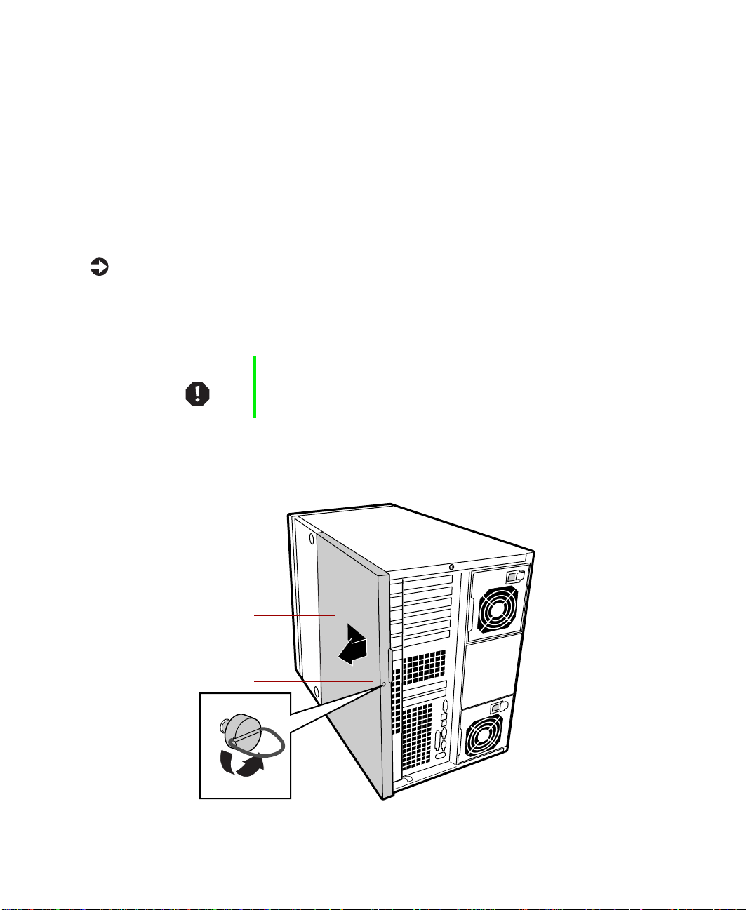
To remove the top panel:
1 Turn off system power, then disconnect the power cord and all the
peripherals.
2 Make sure the server is on a stable surface, such as a table or counter.
Warning In order to avoid injury or dropping the server, Gateway
recommends that two people lift the server.
3 Unscrew the captive thumbscrew on the back access panel.
4 Slide the back access panel toward the back, then pull outward to remove.
Back access panel
Captive thumbscrew
2 Installation
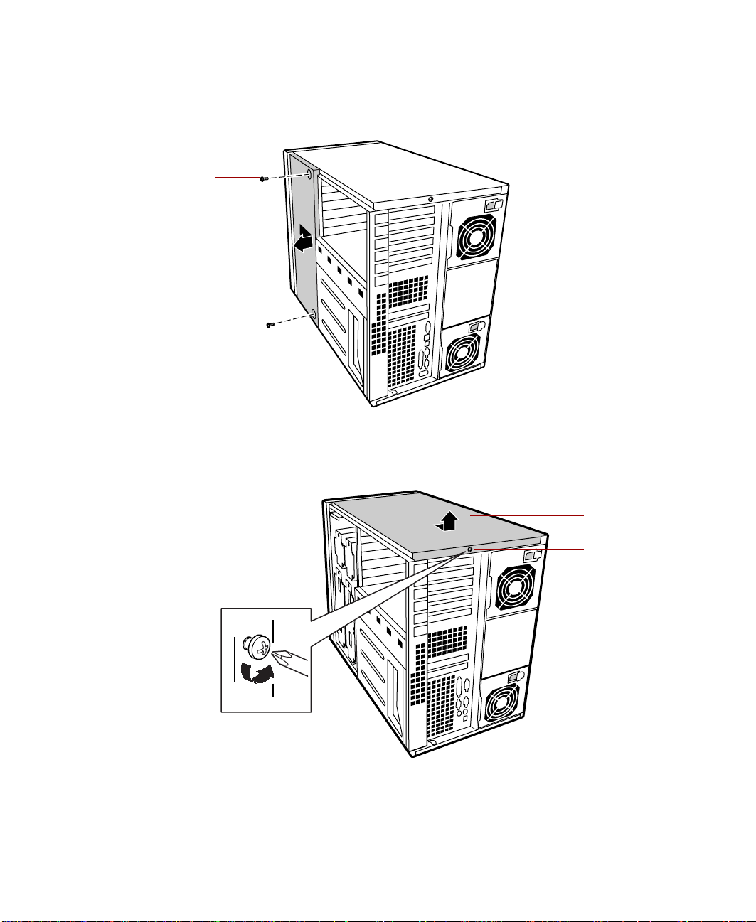
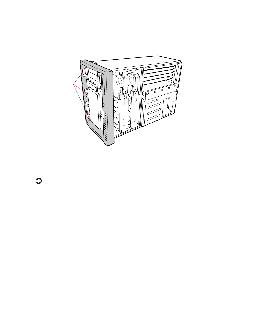
Remove the two screws securing the front access panel to the chassis.
5
6 Slide the front access panel to the back and pull outward to remove.
Screw
Front access
panel
Screw
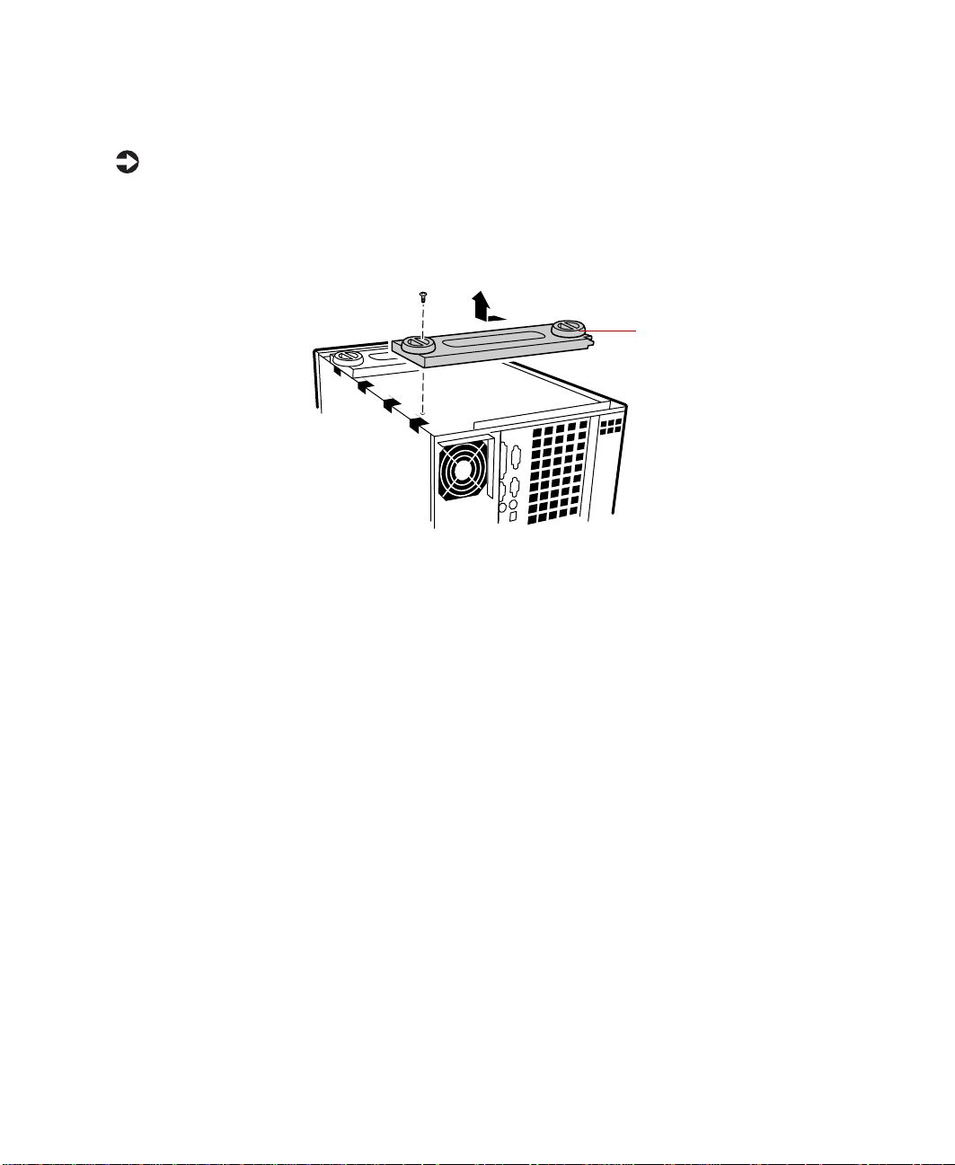
7 Remove the single screw securing the top to the chassis.
8 Slide the top panel to the back, then pull it off.
9 Replace the front and back side access panels.
Converting to rackmount 3
Top panel
Screw
Changing the bezel
To remove the tower bezel:
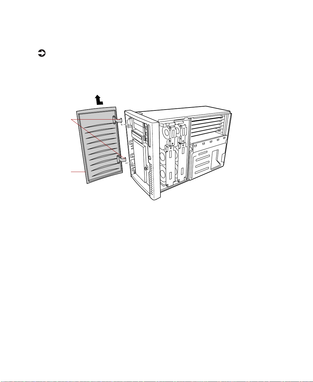
1 With the tower in the upright position, open the system door and lift
the door so that the hinge pins (2) come out of the hinge-pin sockets.
2 Pull the door away from the bezel and set it aside.
Hinge pins
System door
4 Installation
Beginning at the top left inside edge of the bezel, depress the plastic
3
retention tabs toward the outside edge of the bezel, and pull the bezel
out from the chassis slightly, enough to keep the tabs from snapping back
into place.
Retention tabs
Note: other
retention tabs
not visible
4 Work your way around the bezel until all eight tabs (three left, one
bottom, two right, and two top) have been released, then pull the bezel
off the chassis.
To install the rack bezel:
1 Align the rack bezel with the chassis, just as the tower bezel was aligned
prior to removal. Make sure the plastic retention tabs line up with the
appropriate slots in the chassis.
2 Press the rack bezel onto the chassis until the retention tabs snap into
place.
3 Align the door with the chassis, just as it was aligned prior to removal.
4 Insert the hinge pins (2) into the hinge-pin sockets, allowing the door
to fall into place, then close the door.
Converting to rackmount 5
Removing the feet
To remove the feet:
1 Turn the server upside down.
2 Using a flat-bladed screwdriver, remove the screws securing the feet to
the bottom of the chassis.
3 Slide each foot to the left, releasing it from the chassis, then remove.
Foot
6 Installation
Installing the ch assis handles
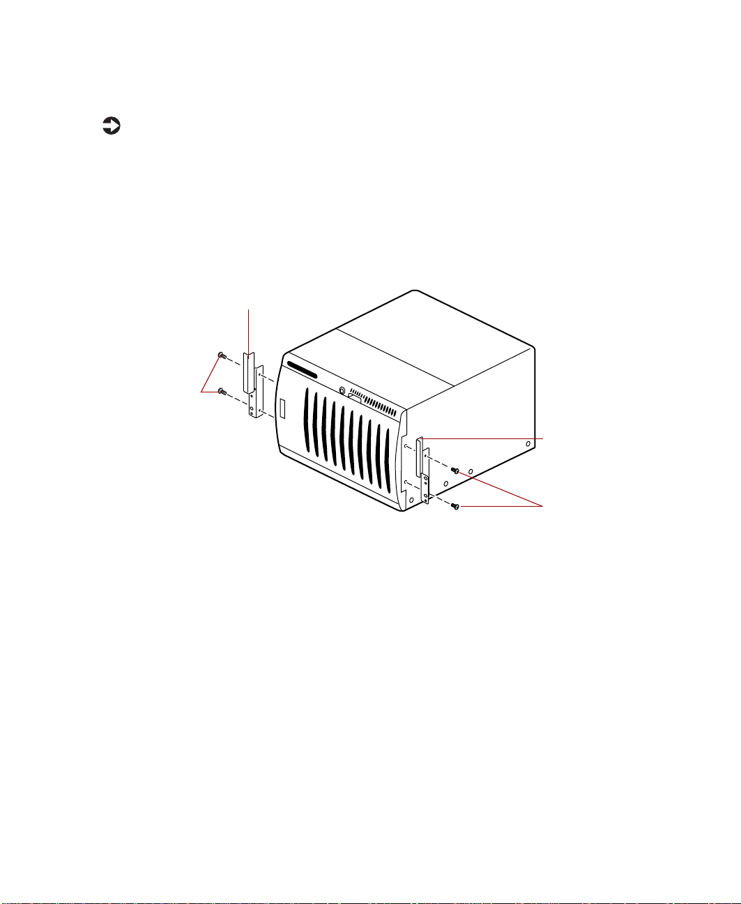
To install the chassis handles:
1 Place the server on its side, like it will be installed in the rack.
2 Orient the handles so that the screw holes on the edge of the handle align
with the screw holes in the chassis (there are rectangular cutouts in the
sides of the bezel where the handles will be installed).
3 Using four screws from the kit (2 for each handle), attach the handles
to the chassis.
Handle
Screws
Handle
Screws
Converting to rackmount 7
Installing the system drawer side rails
Before installing the server (system drawer) in the cabinet, you need to install
the system drawer side rails on the server.
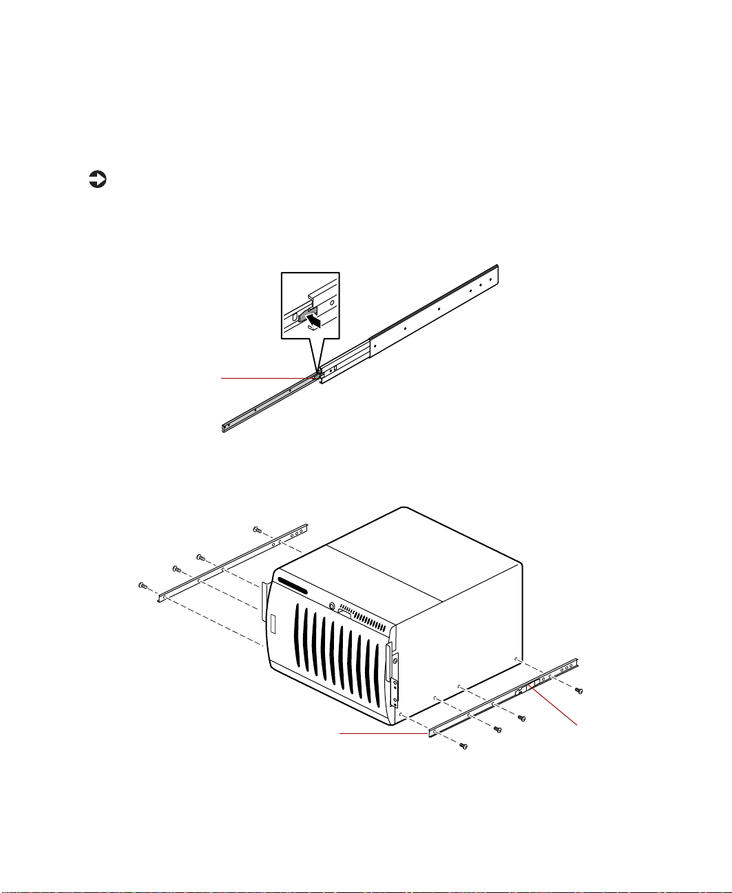
To install the system drawer side rails:
1 Remove the system drawer side rails from the cabinet mounting rails by
depressing the retention clips on the inside of the system drawer side
rails, then sliding the rails off.
Retention clip
2 Mount the system drawer side rail on the server using 4 screws from the
accessory kit. Make sure the retention clips are at the back of the server.
3 Mount the second rail on the opposite side of the server.
8 Installation
Guide rail Retention clip

Installing the cabinet mounting brackets and mounting rails
If you are installing the server in a Gateway cabinet, refer to the following
section. If you are installing the server in a non-Gateway cabinet, go to
“Installing generic mounting brackets” on page 13.
Installing Gateway mounting br ackets
If Gateway mounting brackets are already installed in the cabinet, go to
“Installing the cabinet mounting rails onto Gateway brackets” on page 11.
To install the Gateway mounting brackets in the cabinet:
1 If you received a mounting template with your cabinet, use it to locate
the exact position of the cabinet mounting brackets.
Caution When considering the position of the system in the cabinet,
make sure that a hazardous stability condition is not
created because of uneven loading.
2 Position the front mounting bracket (labeled FRONT) on the front
vertical mounting rail.
Installing the cabinet mounting brackets and mounting rails 9

3 Attach the front mounting bracket to the front vertical mounting rail
using two screws from the accessory kit.
Back mounting
bracket
Front mounting
bracket
Front vertical
mounting rail
Back vertical
mounting rail
4 Position the back mounting bracket (labeled REAR) on the back vertical
mounting rail.
5 Attach the back mounting bracket to the back vertical mounting rail
using two screws from the accessory kit.
6 Mount the second set of brackets on the opposite side of the cabinet by
repeating Steps 2 through 5.
10 Installation
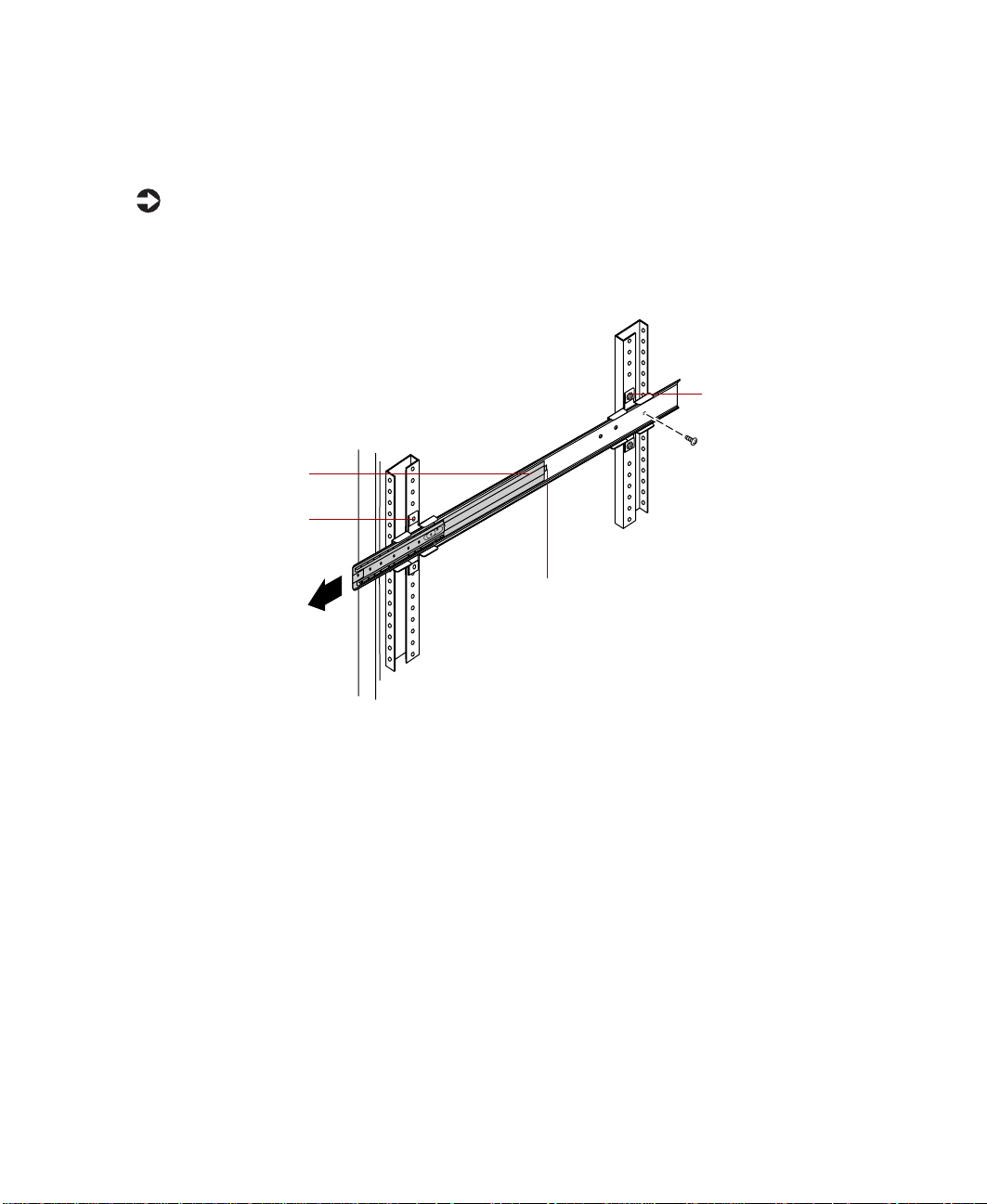
Installing the cabinet mounting rails onto Gateway brackets
To install the cabinet mounting rails onto Gateway brackets:
1 Align the back end of the cabinet mounting rail to the back mounting
bracket by sliding the inner rail forward (if the spring latch locks the inner
rail into place, free the rail by releasing the spring latch).
Back mounting
bracket
Inner rail
Front mounting
bracket
Spring latch
2 Attach the back end of the cabinet mounting rail to the back mounting
bracket using a screw from the accessory kit.
Installing the cabinet mounting brackets and mounting rails 11

3 Align the front of the cabinet mounting rail to the front mounting
bracket by sliding the inner rail and inner slide until the rail screw hole
opening lines up with one of the front mounting bracket screw holes.
Cabinet mounting rail
Inner rail
Inner slide
Spring latch
Screw hole
4 Attach the front of the cabinet mounting rail to the front mounting
bracket using a screw from the accessory kit.
5 Attach the second screw to the front mounting bracket by repeating
Steps 3 and 4.
6 Mount the second cabinet mounting rail on the opposite side of the
cabinet by repeating Steps 1 through 5.
7 Go to “Mounting the system drawer in the cabinet” on page 16.
12 Installation

Installing generic mounting bracket s
If you are installing the server in a non-Gateway cabinet, use the generic
mounting brackets. These brackets allow for different cabinet depths. If
generic mounting brackets are already installed in the cabinet, go to
“Installing the cabinet mounting rails onto generic brackets” on page 14.
To install the generic mounting brackets in the cabinet:
1 If you received a mounting template with your cabinet, use it to locate
the exact position of the cabinet mounting brackets.
Caution When considering the position of the system in the cabinet,
make sure that a hazardous stability condition is not
created because of uneven loading.
2 Position the front mounting bracket (shorter bracket) on the front vertical
mounting rail.
3 Attach the front mounting bracket to the front vertical mounting rail
using two screws from the accessory kit.
If screw holes in the front vertical mounting rail are not threaded, attach
the front mounting bracket by using the screws and bar nut from the
accessory kit.
Front vertical
mounting rail
Front mounting
bracket
Back vertical
Bar nuts
Installing the cabinet mounting brackets and mounting rails 13
mounting rail
Back mounting
bracket
4 Position the back mounting bracket (longer bracket) on the back vertical
mounting rail.
5 Attach the back mounting bracket to the back vertical mounting rail
using two screws from the accessory kit.
If screw holes in the back vertical mounting rail are not threaded, attach
the back mounting bracket by using the screws and bar nut from the
accessory kit.
6 Mount the second set of brackets on the opposite side of the cabinet by
repeating Steps 2 through 5.
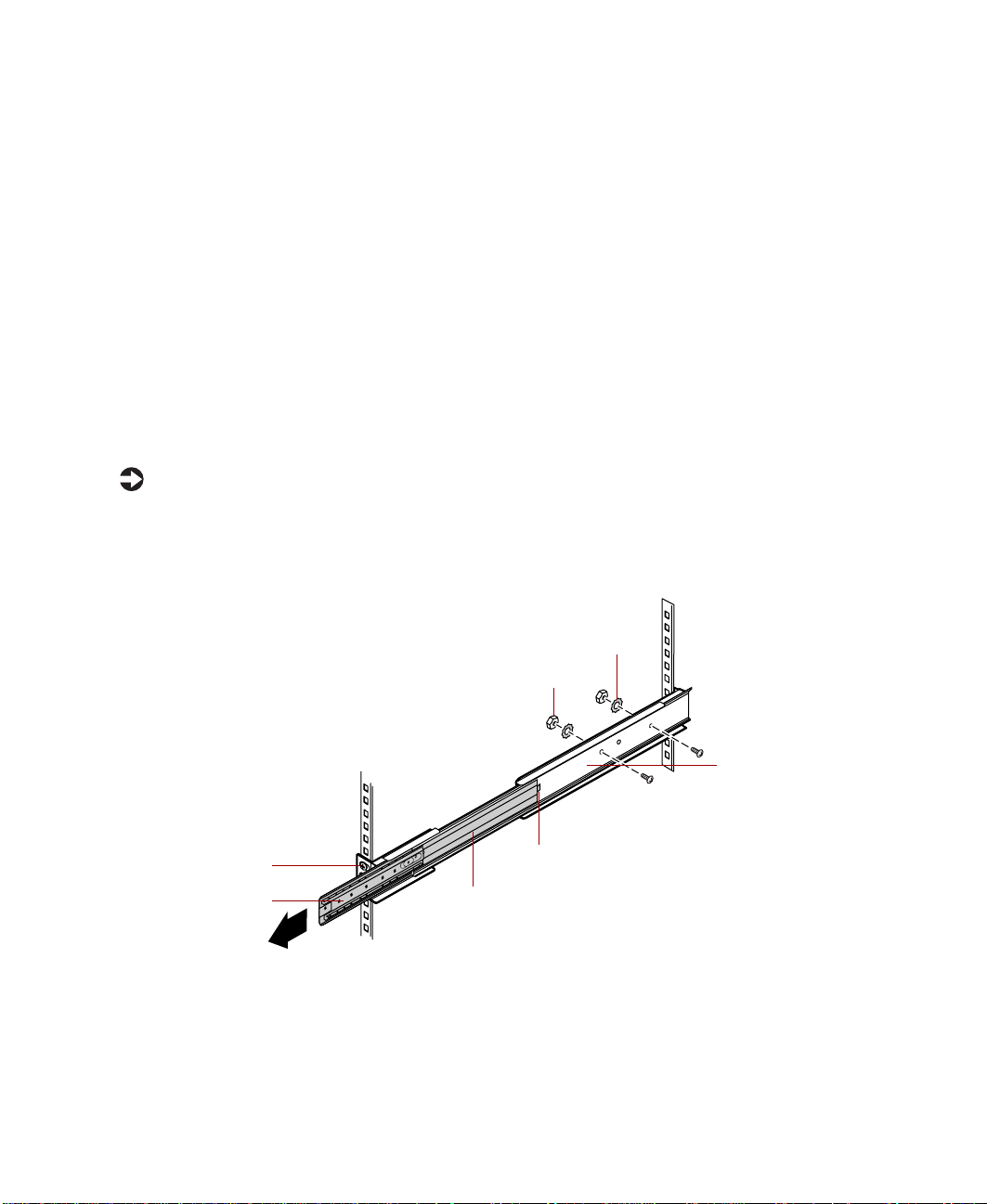
Installing the cabinet mounting rails onto generic brackets
To install the cabinet mounting rails onto generic brackets:
1 Align the back end of the cabinet mounting rail to the back mounting
bracket by sliding the inner rail forward (if the spring latch locks the inner
rail into place, free the rail by releasing the spring latch).
Star washer
Front mounting
bracket
Inner slide
14 Installation
Hex nut
Back mounting
bracket
Spring latch
Inner rail

Attach the back end of the cabinet mounting rail to the back mounting
2
bracket using two screws, hex nuts, and star washers from the accessory
kit.
One screw must be located in the last back bracket screw hole. The second
screw can be located in any of the other back bracket long screw holes.
3 Align the front of the cabinet mounting rail to the front mounting
bracket by sliding the inner rail and inner slide until the rail screw hole
opening lines up with the first inner rail screw hole and with the second
screw hole on the front mounting bracket.
Inner rail
Inner slide
Spring latch
Cabinet mounting rail
4 Attach the front of the cabinet mounting rail to the front mounting
bracket using a screw from the accessory kit.
5 Slide the inner rail and the inner slide again until the rail screw hole
opening lines up with the front mounting bracket long screw hole.
6 Attach the front of the cabinet mounting rail to the front mounting
bracket using a screw from the accessory kit.
7 Mount the second cabinet mounting rail on the opposite side of the
cabinet by repeating Steps 1 through 6.
Installing the cabinet mounting brackets and mounting rails 15

Mounting the system drawer in the cabinet
To mount the system drawer in the cabinet:
1 Pull both of the inner rails forward until the spring latches on each side
lock.
2 Pull the inner slides all the way forward.
Inner rail
Inner slide
Spring latch
16 Installation

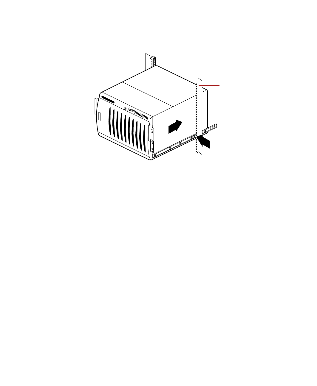
Lift the system drawer to the same height as the inner rails, then align
3
the system drawer side rails with the inner slides.
Warning In order to avoid injury or dropping the server, Gateway
recommends that two people lift the system drawer.
Cabinet mounting
rail
System drawer
side rail latch
System drawer
side rail
4 Push the system drawer evenly into the cabinet until the latches on the
system drawer side rails lock.
Mounting the system drawer in the cabinet 17
5 Press the latches on both sides of the system drawer side rails, then push
the system drawer back until the inner rail spring latches lock.
Cabinet
mounting rail
System drawer
side rail latch
System drawer
side rail
6 From the back side of the cabinet, release the spring latch on the inner
rail while pushing the system drawer to the back of the cabinet.
The first time the system drawer is pushed back into the cabinet there
may be some restriction of movement. The drawer should move
smoothly, without binding or restriction thereafter. If there is still
restriction of movement, make sure all rails and brackets are aligned
properly.
18 Installation

Installing the cable retractor
Cable retractors reduce strain on the drawer cables and connectors and
simplify maintenance because they keep the cables out of the way. If you are
installing a cable retractor in a Gateway cabinet, refer to the following section.
If you are installing a cable retractor in a non-Gateway cabinet, go to
“Installing a cable retractor in a non-Gateway cabinet” on page 20.
Installing a cable retractor in a Gateway cabinet
To install a cable retractor in a Gateway cabinet:
1 Position the cable retractor adapter bracket on the back vertical mounting
rail, then align the mounting holes on both the adapter bracket and the
back vertical mounting rail.
2 Attach the adapter bracket to the back vertical mounting rail using two
screws from the accessory kit. The retractor may be mounted above or
below the level of the system drawer.
Back vertical
mounting rail
Adapter bracket
Cable retractor
3 Go to “Attaching the cables to the retractor” on page 21.
Installing the cable retractor 19

Installing a cable retractor in a non-Gateway cabinet
To install a cable retractor in a non-Gateway cabinet:
1 Remove the adapter bracket from the cable retractor straight bracket.
Adapter bracket
Straight bracket
2 Position the cable retractor straight bracket on the back vertical mounting
rail, then align the mounting holes on both the cable retractor bracket
and the back vertical mounting rail.
3 Attach the bracket to the back vertical mounting rail using a bar nut and
screws from the accessory kit. The retractor may be mounted above or
below the level of the system drawer.
Back vertical
mounting rail
Bar nut
20 Installation
Straight bracket
Cable retractor

Attaching the cables to the retractor
To attach the cables:
1 Route the cables from the back of the system drawer to the cable retractor.
2 Attach the cables to the cable retractor, making sure the cables have
sufficient slack when the system drawer is pulled forward and pushed
back into place.
Cable retractor
3 Route the cables to their destinations and attach as necessary.
4 If necessary, bundle any excess cable.
Completing the connections
Now that the system drawer is installed in the cabinet, make the system
connections.
Important A wide variety of system connections are possible. Your
actual system connections may be different from the
following examples.
Cable
Completing the connections 21

Connecting a single system drawer
To connect the peripherals:
1 Turn off all system drawers and devices in the cabinet before attaching
any of the system drawer cables.
2 Connect all I/O device cables (keyboard, mouse, video, serial, and
parallel) to their respective ports on the back of the system drawer.
The system board connectors may appear different than in the
illustration, depending on your system board.
To power source
Mouse
Keyboard
To monitor
To print e r
SCSI bus
Tape storage
drawer
Mouse and
keyboard tray
22 Installation

Connecting multiple system drawers
Multiple system drawers installed in a cabinet can share a single set of
peripherals if a switch box, such as an autoswitcher, is installed.
To connect multiple system drawers:
1 Turn off all system drawers and devices in the cabinet before attaching
any of the system drawer cables.
The autoswitcher gives control of the monitor and routes the keyboard
and mouse inputs to the currently selected system drawer. Installation
of the autoswitcher is relatively simple and covered in detail in the
autoswitcher user manual.
2 If the newly installed system drawer will control other drawers in the
cabinet, connect the external data cables of the controller cards to the
controlled devices.
3 Connect all I/O device cables (keyboard, mouse, video, serial, and
parallel) to their respective ports on the back of the system drawer.
Completing the connections 23

The system I/O connectors may appear different than in the illustration,
depending on the system board installed in the server.
If connecting multiple system drawers, you must connect extender cables to
the system drawers used. You must also attach the peripherals to the
appropriate I/O ports on the back of the autoswitcher. Refer to the following
figure for connection details.
Tape storage drawer
SCSI channel 1
SCSI channel 2
Example
system
To powe r
Mouse
Keyboard
To print e r
VGA video signal
Autoswitcher
To VGA
monitor
To power source
Keyboard and mouse tray
QHSII storage
drawer
VGA video
signal
To prin t e r
To power source
24 Installation
Mouse
Keyboard
Tape storage
drawer
SCSI channel 2
SCSI channel 1
Second system drawer
QHSII storage
drawer

Connecting the power
Gateway recommends that a licensed electrician install a dedicated 230 VAC
line, with sufficient amperage rating for the system drawer, to a breaker box
or distribution panel. The power cords must be wired directly into the breaker
box.
If you use 115 VAC, make sure not to overload any power strip or wall outlet.
Observe the following guidelines:
■ Only one system drawer per power strip (15 or 20 amps) or wall outlet
(15 or 20 amps). For critical applications, plug the system drawer power
cords into separate circuits.
■ If an uninterruptible power supply (UPS) is installed, plug only one
system drawer into it.
■ Check the ratings on the nameplate to make sure that the supply circuits
are not overloaded.
The power cords must be routed through the cabinet floor opening and to
the system drawer. Make sure that the electrical demands are balanced and
that the system is grounded. Make sure the power supply connections are not
overloaded when connecting to power strips.
Depending on the plug-in configuration, the following devices may share the
same power strip:
Plug-in
Power Strip Total Supported Devices
Configuration
230 VAC 15 amp
20 amp
■
System drawer
■
QHS storage drawer
■
Tape storage drawer
Total must not exceed 12 amps
■
System drawer
■
QHS storage drawer
■
Tape storage drawer
■
Monitor
■
autoswitcher
Total must not exceed 12 amps
Completing the connections 25

Plug-in
Configuration
Power Strip Total Supported Devices
115 VAC 15 amp
20 amp
If rack mounted units are installed in a closed or multi-rack cabinet, they may
require further evaluation by Certification Agencies. The ambient temperature
within the cabinet may be greater than room temperature. Make sure the
amount of air flow required for safe operation is not compromised. The
maximum temperature for this environment must not exceed 122
■
System drawer only
■
System drawer with other
peripherals not to exceed a total of
16 amps for the whole strip.
T urning on the system drawer
To turn on the system drawer for the first time:
1 If using a UPS, turn it on first.
2 Turn on the monitor and any additional devices connected to the system
drawer. Listen for alarms which may indicate power problems.
3 If multiple system drawers and a switch box are installed, press the switch
box button that corresponds to the system drawer being turned on.
°(50C).
4 Press the ON/OFF button on the system drawer.
Important If multiple system drawers are installed, you must turn on
5 Listen for alarms which may indicate power problems.
6 Make sure the power indicator is illuminated. The monitor should display
the normal Power On Self-Test (POST) information. If the monitor does
not display information or the system drawer indicates an error has
occurred, refer to the server system manual troubleshooting section.
26 Installation
each system drawer and wait for it to start completely
before turning on the next system drawer.

When the system drawer starts successfully, install the operating system,
7
if necessary.
8 Turn on the other system drawers by repeating Steps 3 through 7 for each
additional system drawer installed.
After this procedure, the system drawer can be turned on using normal start
sequences.
To turn on the system drawer using normal start sequences:
1 Turn on devices and drawers attached to the system drawer first.
2 When the devices and drawers attached to the system drawer are running,
turn on the system drawer.
T urning off the system drawer
To turn off the system drawer:
1 Close all programs.
2 If necessary, issue a “flush” command to write the contents of any caches
or buffers to disk.
3 If necessary, issue a command to exit or quit the operating system.
4 Press the ON/OFF switch on the system drawer.
5 Turn off any other devices and drawers connected to the system drawer.
Turning off the system drawer 27

Securing the system drawer in the cabinet
To secure the system drawer:
1 Close the back door of the system cabinet, then lock it if necessary.
2 Push the system drawer all the way back into the cabinet until the front
panel presses against the front vertical mounting rails.
3 Secure the system drawer to the front vertical mounting rails using four
screws from the accessory kit.
4 Close the front cabinet door, then lock it if necessary.
28 Installation

A MAN US 8400 RACK GDE R0 5/00
 Loading...