


Maintaining and
Troubleshooting
the Gateway
ALR 9200 Server
Part # 8503424 A MAN SYS US 9200 TECH REF R0 8/98
In our effort t o u se na tur e’s resources e f fici entl y a nd wi sely, we print all man uals on r ecy cled paper s t hat me et the
minimum requirements established by the Federal EP A in it s guidelines for rec ycled paper products.

Notices
Copyright © 1998 Gateway 2000, Inc.
All Rights Reserved
610 Gateway Drive
N. Sioux City, SD 57049 USA
All Rights Reserved
This publication is protected by copyright and all rights are reserved. No part of it may be reproduced or
transmitted by any means or in any form, without prior consent in writing from Gateway 2000.
The information in this manual has been carefully checked and is believed to be accurate. However,
changes are made periodically. These changes are incorporated in newer publication editions. Gateway
2000 may improve and/or change products described in this publication at any time. Due to continuing
system improvements, Gateway 2000 is not responsible for inaccurate information which may appear in
this manual. For the latest product updates, consult the Gateway 2000 web site at www.gateway .com. In
no event will Gateway 2000 be liable for direct, indirect, special, exemplary, incidental, or consequential
damages resulting from any defect or omission in this manual, even if advised of the possibility of such
damages.
In the interest of continued product development, Gateway 2000 reserves the right to make
improvements in this manual and the products it describes at any time, without notices or obligation.
T rademark Acknowledgments
AnyKey, black-and-white spot design, CrystalScan, Destination, EZ Pad, EZ Point, Field Mouse, Solo,
T elePath, Vivitron, stylized “G” design, and “You’ve got a friend in the business” slogan are registered
trademarks and GATEWA Y, Gateway Solo, green stylized GATEWAY , gr een stylized Gateway logo, and
the black-and-white spotted box logo are trademarks of Gateway 2000, Inc. Intel, Intel Inside logo, and
Pentium are registered trademarks and MMX is a trademark of Intel Corporation. Microsoft, MS, MS-DOS,
and Windows are trademarks or registered trademarks of Microsoft Corporation. All other product names
mentioned herein are used for identification purposes only, and may be the trademarks or registered
trademarks of their respective companies.
Copyright © 1998 Advanced Logic Research, Inc. (ALR)
All Rights Reserved
9401 Jeronimo
Irvine, CA 92618 USA
All Rights Reserved
This publication is protected by copyright and all rights are reserved. No part of it may be reproduced or
transmitted by any means or in any form, without prior consent in writing from ALR.
The information in this manual has been carefully checked and is believed to be accurate. However,
changes are made periodically. These changes are incorporated in newer publication editions. ALR may
improve and/or change products described in this publication at any time. Due to continuing system
improvements, ALR is not responsible for inaccurate information which may appear in this manual. For the
latest product updates, consult the A LR web site a t www.alr.com. In no even t will ALR b e li able for dire ct,
indirect, special, exemplary, incidental, or consequential damages resulting from any defect or omission in
this manual, even if advised of the possibility of such damages.
In the interest of continued product development, ALR reserves the right to make improvements in this
manual and the products it describes at any time, without notices or obligation.
T rademark Acknowledgments
ALR is a registered trademark of Advanced Logic Research, Inc. All other product names mentioned
herein are used for identification purposes only, and may be the trademarks or registered trademarks of
their respective companies.
Some portions of this document are copyright © 1998, Intel Corporation.

Contents
Preface .....................................................................................vii
About This Guide................................................................................ viii
Conventions Used in This Guide........................................................... ix
Important Safety Instructions.................................................................. x
Chapter 1: System Access ........................ ......... .......... ......... ...1
Static Electricity Precautions.................................................................. 2
Opening the System ................................................................................ 3
Removing the Access Cover............................................................ 3
Opening the Front Door................................................................... 4
Opening the Subchassis and Electronics Bay................................. 5
Closing the System.................................................................................. 7
Closing the Subchassis and Electronics Bay................................... 7
Installing the Access Cover.............................................................. 8
Installing the Front Door.................................................................. 8
Chapter 2: Componen ts ......... ......... .......... ..... ......... ......... ........9
System Board Features.......................................................................... 10
System Board Connectors..................................................................... 10
Drive Controllers and Connectors................................................. 12
System Jumpers (B)....................................................................... 13
Miscellaneous Connectors............................................................. 14
Expansion Slot Connectors............................................................ 15
Memory Module Connector (I)..................................................... 16
System Management Connectors.................................................. 16
Back Panel I/O Connectors............................................................ 18
Processors and Related Connectors............................................... 20
Power Connectors.......................................................................... 21
Memory.................................................................................................. 23
DIMM Installation Sequence......................................................... 24
System Memory Addressing ......................................................... 24
Memory Configuration.................................................................. 25
System Security..................................................................................... 26
Mechanical Locks and Monitoring................................................ 26
Software Locks via the SSU or BIOS Setup................................. 26
Contents i

Chapter 3: Installing Co mponents ................................ ......... ..31
Introduction........................................................................................... 32
Replacing the Processor........................................................................ 32
Installing Another Processor................................................................ 36
Installing Hardware............................................................................... 40
Memory.......................................................................................... 40
Drives............................................................................................. 45
Installing Fans for High-Power Drives......................................... 57
Expansion Cards............................................................................ 62
Power Supplies .............................................................................. 65
Replacing the Battery .................................................................... 68
Chapter 4: Jumpers and Drivers .................... ................... ......71
Setting the Jumpers............................................................................... 72
Changing a Jumper Setting............................................................ 73
CMOS Clear Jumper..................................................................... 74
Password Clear Jumper................................................................. 75
Recovery Boot Jumper.................................................................. 75
Installing Software and Drivers............................................................ 77
Installing Video Drivers................................................................ 77
Chapter 5: BIOS Set up .................... ......... ..... ......... .......... ......79
Introduction........................................................................................... 80
Using BIOS Setup................................................................................. 81
Record Your Setup Settings.......................................................... 81
If You Cannot Access Setup ......................................................... 82
Starting Setup................................................................................. 82
Setup Menus.......................................................................................... 83
Setup Key Commands................................................................... 84
Special Display Items.................................................................... 84
Main Menu..................................................................................... 85
Advanced Menu............................................................................. 87
Security Menu................................................................................ 92
Server Menu................................................................................... 93
Boot Menu...................................................................................... 95
Exit Menu....................................................................................... 97
ii Maintaining and Troubleshooting the Gateway ALR 9200 Server

Upgrading the BIOS.............................................................................. 98
Preparing for the Upgrade.............................................................. 98
Upgrading the BIOS..................................................................... 100
Recovering the BIOS................................................................... 101
Changing the BIOS Language..................................................... 101
Chapter 6: The Server Setup Utility ............................... ........103
Introduction.......................................................................................... 104
Using the System Setup Utility........................................................... 105
When to Run the SSU.................................................................. 105
What You Need to Do.................................................................. 106
Running the SSU................................................................................. 107
Running the SSU Locally............................................................ 107
Running the SSU Remotely......................................................... 107
Starting the SSU........................................................................... 108
Customizing the SSU.......................................................................... 109
Launching a Task ................................................................................ 111
Resource Configuration Add-in Window.......................................... 112
Using the RCA Window.............................................................. 112
Defining an ISA Board................................................................. 113
Adding and Removing ISA Boards............................................. 114
Modifying Resources................................................................... 114
System Resource Usage............................................................... 115
Multiboot Options Add-in................................................................... 115
Security Add-in ................................................................................... 116
Security Options........................................................................... 117
System Event Log Viewer Add-in...................................................... 118
Sensor Data Record Manager
Add-In.................................................................................................. 120
Field Replaceable Unit Manager Add-In........................................... 122
Exiting the SSU................................................................................... 124
Chapter 7: Other Utilities ............................ ......... .......... ........125
Introduction.......................................................................................... 126
Power-on Self Test.............................................................................. 127
Emergency Management Port Console.............................................. 129
How the EMP Console Works..................................................... 130
EMP Console Requirements........................................................ 132
Contents iii

Setting Up the Server for the EMP.............................................. 133
Main EMP Console Window...................................................... 134
Server Control Operations........................................................... 136
Phonebook.................................................................................... 140
Management Plug-ins.................................................................. 141
FRU and SDR Load Utility................................................................ 145
When to Run the FRUSDR Load Utility.................................... 145
What You Need to Do................................................................. 145
How You Use the FRUSDR Load Utility.................................. 146
Cleaning Up and Exiting............................................................. 150
Using the Firmware Update Utility.................................................... 151
Running the Firmware Update Utility........................................ 151
Using the Symbios SCSI Utility......................................................... 152
Running the SCSI Utility............................................................. 152
Chapter 8: Troubl eshoot ing .................................... .......... ....153
Introduction......................................................................................... 154
Computer Virus Notice....................................................................... 155
Viruses.......................................................................................... 155
Types of Viruses.......................................................................... 155
Virus Contamination.................................................................... 155
Protecting Your System............................................................... 156
Virus Prevention.......................................................................... 156
Troubleshooting Checklist ................................................................. 158
Verifying the Configuration........................................................ 158
Troubleshooting Guidelines........................................................ 158
Solving Problems................................................................................ 159
Resetting the System.................................................................... 159
Initial System Startup................................................................... 159
Running New Application Software........................................... 160
The System Has Been Running Correctly.................................. 161
More Problem-solving Procedures............................................. 162
Specific Problems and Corrective Actions................................. 164
Error and Informational Messages..................................................... 170
POST Codes and Countdown Codes.......................................... 170
POST Error Codes and Messages............................................... 173
iv Maintaining and Troubleshooting the Gateway ALR 9200 Se rver

Appendix A: Reference Data ..................... ................... ........175
Specifications....................................................................................... 176
System Specifications.................................................................. 176
Environmental Specifications...................................................... 177
System I/O Addresses......................................................................... 178
Memory Map....................................................................................... 181
Interrupts.............................................................................................. 182
Video Modes ....................................................................................... 183
DMA Usage......................................................................................... 187
Appendix B: Regulatory Compliance Statements ................ 189
Electromagnetic Compatibility........................................................... 190
FCC Notice.......................................................................................... 191
Industry Canada Notice....................................................................... 192
CE Notice............................................................................................. 192
VCCI Notice........................................................................................ 193
Australia/New Zealand Notice ........................................................... 193
Declaration of the Manufacturer or Importer..................................... 194
Safety Compliance.............................................................................. 194
Index ..................................................................................... 195
Contents v

vi Maintaining and Troubleshooting the Gateway ALR 9200 Server

Preface
Contents
About This Guide .................................................viii
Conventions Used in This Guide...........................ix
Important Safety Instructions.................................. x

About This Guide
This document pro vides step-b y-step install ation instructions along with
detailed illustrations to hel p maintain the hardw are component s and
peripherals of the computer.
Chapter 1: Sy stem Access pro vides instructions on opening a nd closing the
case.
Chapter 2: Component s covers information on maintai ning, replacing, and
upgrading the components in the system. This sect ion includes information
about options for the system and inst allation instructions.
Chapter 3: Installing Components describes the procedures for install ing or
replacing the hardwa re components.
Chapter 4: Jumpers and Drivers describes setting the jumpers and pro v ides
basic information about operating systems and sof twar e.
Chapter 5: BI OS Setup br iefly e xplains the syst em basic input/output
system (BIOS) and pro vides instructions on ho w to update the BIOS.
Chapter 6: The S erver Setup Utility describes the system setup util ity and
provides instructions on using it to set up the server .
Chapter 7: Othe r Utilities de scribes the other uti lities pro vided wit h the
system and pro vides instructions for their use.
Chapter 8: Troubleshooting provides refer ence material on troub leshooting
your system.
viii Maintaining and Troubleshooting the Gateway ALR 9200 Server
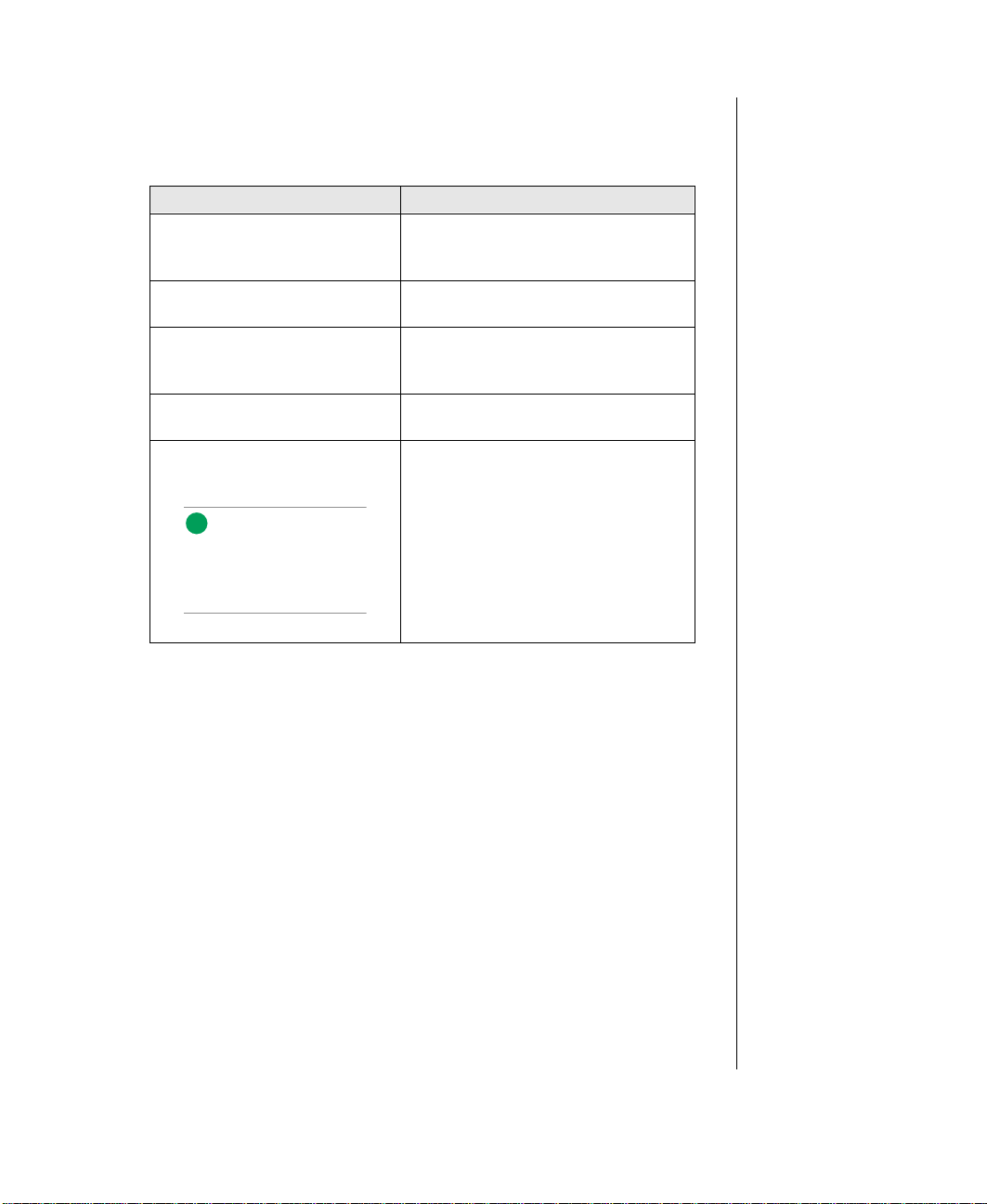
Conventions Used in This Guide
Note:
This is an ex ampl e of an
important note that may
appear in the manual.
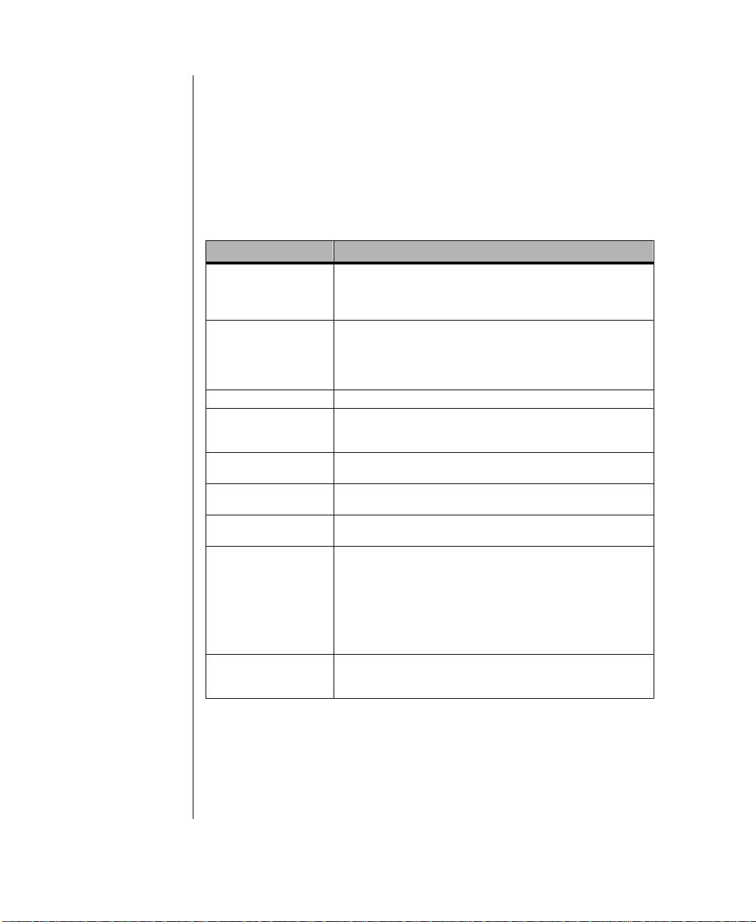
Throughout this document, you will see the follo wing co n ventions:
Convention Description
ENTER
CTRL+ALT+DEL
Setup
User’s Guide
Sidebars Sidebars give critical information such
Key names, which correspond to keys
on the keyboard, are printed in small
capitals.
A plus sign indicates that the keys
must be pressed simultaneously.
Commands to be entered, options to
select, and messages that appear on
your monitor are printed in bold.
Names of publications and files are
printed in italic.
as warnings and important notes.
Conventions Used in This Guid e i x

Important Safety Instructions
Warning!
Do not attempt to se rvi ce
the system yourself except
as explained el sewh er e i n
the manual. Ad just onl y
those controls covered in
the instruct ions .
Opening or removing covers
marked “Do Not Remove”
may expose you to
dangerous voltages or other
risks.
Refer all servicing of those
compartments t o q ual ifi ed
service personnel.
Important!
The system power cord
serves as the mai n
disconnect for the
computer. The wall outlet
must be easily accessible by
the operator.
Observe the following gui delines w hen performing any w ork on y our
system:
• Foll ow all instructions marked on t he server and in the
documentation.
• Unplug this product from the w all outlet be fore cleaning. Do not
use liquid or aerosol cleaners . Use a damp cloth for cle aning.
• Do not use this product near water . Do not spill liquid on or int o the
server .
• Do not place the server on an unstab le surface.
• Openings in the system cabinet are provi ded for ventilat ion. Do not
block or co ver these openings. Do not place the server near or upon
a radiator or heat re gister .
• Use only the po w er source sho wn on the power suppl y. If you are
not certain about the po wer s ource, ask the local po we r company.
• The server is equipped with a 3-wire grounding plug (a plug wit h a
grounding pin). This plug only fits into a grounded pow er outlet.
This is a safety feature. If y ou are unab le to insert the plug into t he
outlet, contact your e lectrician to repl ace the outlet.
• Do not walk on the po w er cord or allow anything to rest on it.
• If you use an extensi on cord with this system, make sure the total
ampere ratings on the products plugged into the extens ion cord do
not exceed the extensi on cord ampere rating. Also, the total ampere
requirements for all products pl ugged into the w all outlet must not
exceed 15 amperes.
• Never insert objects of any kind i nto the system vent ilation slot s.
x Maintaining and Troubleshooting the Gate way ALR 9200 Serve r
• Unplug the system from the w all outlet and ref er servicing to
qualified personnel if:
• The power cord or plug is damaged.
• Liquid has been spilled into the system.
• The system does not operate properly when t he operating
• The system was dropped or the cabinet is damaged.
• The system’s performance changes.
instructions are follo w ed.

Chapter 1:
System Access
Contents
Static Electricity Precautions.................................. 2
Opening the System................................................. 3
Removing the Access Cover............................ 3
Opening the Front Door................................... 4
Opening the Subchassis and Electronics Bay. 5
Closing the System.................................................. 7
Closing the Subchassis and Electronics Bay... 7
Installing the Access Cover.............................. 8
Installing the Front Door.................................. 8

Static Electricity Precautions
Caution! Prevent Static-Electricity Damage
Static Electricity Preventions
1. WEAR A GROUNDING WRIST STRAP (a vailab le at most electronic stores).
2. Turn off the system pow er .
3. Touch the back of the power supply fan, located on the back of the case.
4. UNPLUG ALL CORDS FR OM WALL OUTLET.
5. Remove the system case cover .
Static Electricity Pr ecautions
♦ Avoid static-causing surfaces such as plastic and styrofoam in your work area.
♦ Remove the parts from their antistatic bags only when y ou are ready to use them. Do not la y
parts on the outside of antistatic bags since only the inside provides antistatic protection.
♦ Always hold cards by their edges and their metal mounting bracket. A void touching
components on the cards and the edge connectors that connect to expansion slots.
♦ Never slide cards or other parts over any surface.
2 Maintaining and Troubleshooting the Gateway ALR 9200 Server

Opening the System
Depending on your purpose, you ma y need to remo v e the access co v er or
both the access co ver and t he bezel. You may also need to open the
subchassis or the electronics bay t o reach certain components. F oll o w the
instructions specific to the item you wish to remo ve or open as indicated in
each section.
Removing the Access Cover
You need to remov e the system access co ve r to reach components inside the
system. F acing the front of the sys tem, the access co ve r is on the right side
of the server .
To Remove the Access Cover
1. Observe the ESD precautions in “Static Ele ctricity Precauti ons” on
page 2.
2. T urn off all peripheral de vices connect ed to the system.
3. T urn off the system by us ing the po wer on/off s witch on the front pane l
and unplugging all A C po w er cords.
Caution!
Power the system off and
disconnect all powe r cords
before proceeding. Installing
any component while the
power is on may cause
permanent damage to the
system.
4. Label and disconnect all peripheral ca bles a ttached to the input/ou tput
(I/O) panel on the back of the syst em.
Opening the System 3

5. Remove and sa ve the three scr ews from the ba ck of the access co v er
(see Figure 1); you will need them later to reat tach the co v er .
Figur e 1: Remo ving the Acces s Cover
6. Place the fingertips of your right hand under the built-in handle on t he
back of the co ver. A rounded , rectangular depres sion in the front
middle of the access co ver serves as another handle.
7. Using an even pull, sl ide the co v er backward, about an inch, until it
stops.
8. Pull the entire co ver outw ard, straight aw a y from the chassi s, to
disengage the ro ws of tabs from the notches i n the top and bottom
edges of the chassis. Set t he co ver a side.
Opening the Front Door
The front door is secured to the bezel b y a ke y lock. This lock has thr ee
positions: full y locked , f ront door unlock ed , and fro nt and access co ve r
unlocked. When the front door is unlock ed , y ou can remo ve it by opening it
fully and lift ing the hinges out of the s lots that hold them.
4 Maintaining and Troubleshooting the Gateway ALR 9200 Server

Opening the Subchassis and Electronics Bay
The chassis is comprised of three pa rts: the main chassis, a s wing-out
subchassis at the front, and a s wing-out subchassi s, called the electr onics
bay, at the rear . To access components in some inst ances, you must re mo ve
the foam cov ers and s wing a wa y and/or completely remo ve the subchassi s
and electronics ba y.
T o open the subchas sis and electron ics ba y, you must first remov e the foam
cov ers. The subchassis and el ectronics ba ys are se cured using phillips hea d
screws.
T o Open the Subchassis and Electronics Bay
1. Observe the safety and ESD precautions in “Stati c Electricity
Precautions” on page 2.
2. T urn off all peripheral de vices connect ed to the system.
3. T urn off the system po w er b y using the po w er o n/off s witch on the
front panel and unplugging all A C po w er c ords.
4. Label and disconnect all peripheral ca bles a ttached to the I/O panel on
the back of the system.
5. Remove and sa ve the three scr ews from the ba ck of the access co v er;
you will need them later t o reattach the co ver.
6. Remove the access co ver.
7. Remove the foam blocks b y pulling t hem out of the subchassis and
electronics ba y . These blocks form an important part of the airflo w and
electromotiv e compatibility (EMC) characteristics o f the system. The
foam in the subchassis also forms the support structure for most of the
system fans.
Opening the System 5

8. Loosen the two sc rews on the t op and bottom edges of t he chassis (A
Caution!
Y ou must di sconnect all
cabling to the e l ect r oni cs
bay before rotating/
removing the bay. Failur e t o
do so can result in serious
damage to system
components. The location of
the main connectors in the
electronics bay is marked as
D in Figure 2.
Note:
It may be easier to
disconnect the cables if you
remove the foam pad first.
in Figure 2). These screws attach the front subcha ssis and the
electronics ba y to the main chassis.
A
B
C
D
Figur e 2: Opening t he Subchassis and Elec tr onics Bay
9. Using the edges of the subchas sis as handles, rotate the front
subchassis left, a w a y from the main chassis, un til it stops (B in
Figure 2).
10. Disconnect all cabling to the el ectronics ba y (D in Fi gure 2).
11. Using the vertical edge of the electr onics ba y as a handle, rotate t he
bay right, a w a y from the main chassis, unt il it stops (C in F igure 2).
12. If necessary , completel y remo v e the subchassis and el ectronics ba y:
rotate the ba ys outward unt il the tw o pins tha t function as hinges for
the bays sli de out of their slots . Set the ba ys aside.
6 Maintaining and Troubleshooting the Gateway ALR 9200 Server

Closing the System
Before closing the system, ver ify that all connect ors and boards are
properly instal led and firmly seated.
Closing the Subchassis and Electronics Bay
As you close the subchassi s and electronics ba y, carefully observe the
internal components to ensure that y ou do not pinch or twist an y of the
cables or components.
To Close the Subchassis and Electronics Bay
1. Verify that all internal components are f ully ins talled and secured.
2. Press down on t he tab on the top of the electronics ba y to release it and
swing it closed.
3. Attach any cab les to the electr onics ba y components.
4. Press down on the tab at the top of the subchassis to free it an d swing it
closed.
5. Secure the subchassis with the two screws you re mo ved earlie r .
6. If necessary , reins tall the foam brack eting for the fans i n the
subchassis and reinstall the fans.
7. Reinstall the foam o ver t he subchassis and electr onics ba y.
8. Replace the access co ver a nd po we r up the system.
Closing the System 7

Installing the Access Cover
Note:
The bezel key lock must be
in the open position before
reinstall ing the a cce ss co ver.
Be careful to a void pinching a ny in ternal cables in the a ccess co ve r when
closing the system.
T o Replace the Access Cover
1. Before replacing the access co v er , check that you ha ve not left loose
tools or parts inside the system.
2. Check that cables, e xpansion cards, f oam pad , and other components
are properly inst alled.
3. Position t he co ver over the chassis so that th e ro ws of tabs align with
slots in the chassis. While pressing inw ard , sli de the co ver to war d the
front of the system until the t abs on the co v er firmly engage in the
chassis.
4. Attach the co ver to the ch assis with the th ree screws y ou remo v ed
earlier, and t ighten them firmly .
5. Connect all external cabl es and the po w er cords to the system.
Installing the Front Door
T o replace th e front door , insert the hinges into the slots on the f ront of the
chassis and close the door . Sec ure it by turning the bezel keylock to the
second locked position. The first position allo ws you to open the front door
and locks the side access panel. The f ully lock ed position pre v ents all
access to the system controls b y lockin g both the access panel and t he bezel
door .
8 Maintaining and Troubleshooting the Gateway ALR 9200 Server

Chapter 2:
Components
Contents
System Board Features...................................................10
System Board Connectors..............................................10
Drive Controllers and Connectors..........................12
System Jumpers (B)................................................13
Miscellaneous Connectors......................................14
Expansion Slot Connectors ....................................15
Memory Module Connector (I)..............................16
System Management Connectors...........................16
Back Panel I/O Connectors ....................................18
Processors and Related Connectors .......................20
Power Connectors...................................................21
Memory...........................................................................23
DIMM Installation Sequence .................................24
System Memory Addressing..................................24
Memory Configuration...........................................25
System Security ..............................................................26
Mechanical Locks and Monitoring ........................26
Software Locks via the SSU or BIOS Setup..........26
System Board Featur es
The system board functions as the main int erface betw een the processor ,
memory , and peripherals.
T able1 lists the features of the system board. F igure 3 on page 11 shows the
components on the system board and their locati ons.
Table 1: System Board Features
Feature Description
Processor Installed: Up to four Pentium® II Xeon™ processors, in single
Main memory Single plug-in module containing 16 dual in-line memory module
Video memory Installed: 2 MB of video memory.
PCI bus(es) PCI-A—Three expansion connectors
ISA bus One expansion slot for expansion boards (shared with a
Server management Thermal/voltage monitoring and error handling.
Graphics Integrated onboard Cirrus Logic GD5480 super video graphics
SCSI Two embedded small computer systems interface (SCSI)
System I/O PS/2-compat ib l e keyboard and mous e p or t s , pa r all el port,
edge contact (SEC) car t r idges installed in Slot 2 connectors.
Includes co nn e ctors for six VRM 8. 3 - co mpliant plug -i n v o lt ageregulator modules (VRMs).
(DIMM) sockets for up to 4 GB of extended data output (EDO)
dynamic ra n dom access memory (DRA M).
Installed: 256 MB–4 GB of EDO error correcting code (ECC)
random access memory (RAM).
PCI-B—Four expansion connectors (one shared with the
ISA slot)
PCI-B slot).
Front panel controls an d indicator light emitting diodes (LE Ds ).
array (SVGA) controller.
controllers:
Symbios SYM53C810AE—narrow SCSI controller providing
support for legacy 8-bit SCSI devices
Symbios SYM53C896—dual-channel wide low voltage
differential (LVD)/single-ended (SE) (ultra2/ultra) SCSI controller
driving one SCSI backplane in the system and providing support
for external expansi o n.
video port, USB port, and two serial ports (serial port 1 is the left
connector).
System Board Connectors
Figure 3 shows the connectors on the system board. Some of thes e
connectors may not be used, depending on the configuration of the server .
The table belo w pro vi des the key t o Figure3.
10 Maintaining and Troubleshooting the Gateway ALR 9200 Se rver

LL
C DA E FB
G
GG
JJ
KK
II
HH
H
I
FF
EE
DD
CC
AA
W
BB
Z
Y
X
V
P
J
K
Q
L
R
S
T
M
N
O
U
Figur e 3: Syst em Board Component s and Connectors
A Wide SCSI B connector (J9J1) T VRM connector for processors 2 & 1 (J4A2)
B System jumpers (J6J1) U VRM connector for processor 1 (J4A1)
C Hard drive input LED connector (J6J3) V Processor 1 Slot 2 connector (J9A1)
D System speaker connector (J6J2) W Main power connector, primary (J9B1)
E Lithium battery (B4H1) X Processor 2 Slot 2 connector (J9B2)
F Wake-on-LAN technology connector (J4H1) Y Processor 3 Slot 2 connector (J9D1)
G ISA slot (J1J1) Z Main power connector, secondary (J9D2)
H PCI slots B4 (top), B3, B2, B1, A3, and A2 AA Front panel connector (J8E1)
I Memory module connector (J3G1) BB Processor 4 Slot 2 connector (J9E1)
J ICMB connector (J1E1) CC IDE connector (J9E2)
K PCI slot A1 (J2D1) DD Diskette drive connector (J9E3)
L Video and parallel port connectors (J1C1) EE Auxiliary power connector (J9E4)
M Serial port connectors (J1B2) FF USB internal header (JC9F14)
N Keyboard and mouse connectors (J1B1) GG SMBus connector (J9F2)
O USB external connector (J1A1) HH F16 expansion connector (J7G1)
P VRM connector for processor 4 (J4E1) II Narrow SCSI connector (J9H1)
Q VRM connector for processors 4 & 3 (J4C2) JJ External IPMB connector (J7H1)
R VRM connector for processor 3 (J4C1) KK SMM connector (J8H1)
S VRM connector for processor 2 (J4B1) LL Wide SCSI A connector (J9H2)
System Board Connect or s 11

Drive Controllers and Connectors
The system board supports sev eral controllers an d connectors for the
control of the var ious driv es that are or can be installed in th e system.
SCSI Connectors
The system board includes tw o SCSI controllers. A narro w SCSI controller
(SYM53C810AE) is on the PCI-A bus, and a dual-channel wide LVD/SE
(Ultra2/Ultra) SCSI controller (SYM53C896) is on t he PCI-B bus. The
narrow controller pro vide s support for lega cy 8-bit SCSI de vices that ma y
be installed in the 5.25-inch dri ve ba ys. The wide cont roller dri ves one
SCSI backplane and pro vides support for external expansion .
Each controller has its o wn set of PCI c onfiguration registers and SCSI I/O
registers. As a PCI 2.1 bus master, the wide controller supports burst dat a
transfers on PCI up to the maximum rate of 132 MB/sec using on-chip
buffers.
No logic, termination, or res istor loads are requi red to connect de vices to
the SCSI controller other than te rmination in the devic e at the end of the
cable. The SCSI bus is terminated on the syste m board with acti ve
terminators that can be disable d.
Wide SCSI A (LL) and Wide SCSI B Connectors (A)
Internally, each wide channel is identi cal, capab le of operations u sing either
8- or 16-bit SCSI pro viding 10 MB/sec ( F ast-10) or 20 M B/sec (F a st-20)
throughput, or 20 MB/sec (Ultra) or 40 MB/sec (Ultra-wide).
The wide controller contains a high-perf ormance SCSI bus interface. It
supports SE mode with 8-bit (10 or 20 MB/sec) or 16-bit (20 or 40 MB/sec)
transfers and LVD mode with 8-bit (40 MB/sec) or 16-bit (80 MB/ sec)
transfers.
Narrow SCSI Connector (II)
The narrow controller contai ns a high-performance SCSI core capab le of
F ast 8-bit SCSI transfer s in single-ended mode. It pr o vides pro grammable
active ne gation, PCI zero w ait- state bursts of faster th an 110 MB/sec at 33
MHz, and SCSI transfer rates from 5 to 10 M B/sec.
12 Maintaining and Troubleshooting the Gateway ALR 9200 Se rver

IDE Connector (CC)
Y
This is an integrated Ultra-DMA PCI/I DE interface with an IDE connector
capable of controll ing up to tw o IDE de vices. Ultra-DMA pro vid es faster
access to IDE devices that are Ultra-DMA complian t while maintaining
support for IDE devices that do not support the Ultr a-DMA specification.
The IDE controller supports:
• PIO and IDE DMA/bus master operations
• Mode 4 timings
• Transfer ra tes up to 33 MB/sec
• Buffering for PCI/IDE burs t transfers
• Master/slav e IDE mode
• Up to two dri ves f or one IDE channel
Diskette Drive Connector (DD)
The diskette dri ve controlle r and connector on the syst em board can support
up to two disk ette dri ves of 1.44-MB and 2.88-MB formats.
Note:
ou can connect an IDE
signal cable, up t o a
maximum of 18 inches, to
the IDE connec tor on the
system board . The cabl e
can support two devices,
one at the end of the cable
and one six inches from the
end.
System Jumpers (B)
These jumpers allo w you to set c ertain characteristics of the s ystem. Some
jumpers are reserved and are not descr ibed in this section. Do not change
any jumper unless it i s necessary to configure the system. In some cases,
changing the settings of reserved j umpers can cause damage to t he system
board.
Clear CMOS Jumper
This jumper allo ws you t o clear the complim entary metal-oxide
semiconductor (CMOS) memory. You should only do this if you cannot
access the normal methods of modifying the CMOS and modifications to
the CMOS are necessary . Clea ring CMOS memory returns all BIOS Setup
settings to the default v alues. This jumper occupi es pins 1-3 of the
connector . See “Setting the J umpers” on page 72 for more information on
setting the CMOS clear jumper.
System Board Connect or s 13

Password Clea r Jumper
Momentarily sett ing this jumper allows you to clear the pass w ords. The
normal jumper position protects the passwords. Use this jumper only if y ou
have f orgotten the pass w ords and cannot a ccess the system. This jumper
occupies pins 5-7 of the connector . Se e “Setting the Jumpers” on page72
for more information on setting the pass w ord clear jumper.
Recovery Boot Jumper
The recov ery boot jumper should be used only i n the ev ent of a fail ed BIOS
update. If you attempt a BIOS update and t he update fails, set this jumper
and reboot the system. The system attempts to recover the previous v ersion
of the BIOS as it boots up. This jumper occupies pins 9-11 of the connect or .
See “Setting the Jumpers” on page 72 for more information on setting the
recov ery boot jumper .
Miscellaneous Connectors
Hard Drive Input LED Connector (C)
This connector allo ws you to connect a cable from an add-in hard di sk
controller to the system board t o allo w the add-in cont roller to acti v ate the
hard drive activit y LED on the control panel .
System Speaker Connector (D)
Connects the internal speaker to the s ystem board.
Wake-on-LAN Technology Connector (F)
The wake on local ar ea netw ork (LAN) technolo gy con nector allo ws y ou to
connect a magic packet-en abled LAN adapter to the system board to
support wake on LAN functionality. Wake on LAN functionality all ows a
system in pow er conserv ation mode to be a w akened b y an incoming
message on the netw ork.
14 Maintaining and Troubleshooting the Gateway ALR 9200 Se rver

Front Panel Connector (AA)
The front panel connector pro vides the signals for the f ront co ver indicator
LEDs and the front co ver buttons.
USB Internal Connector (FF)
This connector allo ws you to connect internal devi ces that use the USB
interface to the USB controller on the s ystem board.
Lithium Battery (E)
Provides the po w er to maintain t he CMOS memory when the sy stem is
turned off or unplugged.
Expansion Slot Connectors
ISA Slot (G)
The system board has one industry standard archite cture (ISA) slot that is
full-length if y ou do not use the wide SCSI-B connector (and half-length if
you use the wide SCSI-B connector); t he ISA slot supports sla ve-onl y
boards and is shared with PCI-B slot 4. The ISA bus also supports three
embedded devices: the SuperI/O chip, system board management
controller (BMC), and flash me mory for the system BIOS. ISA bus
features:
• Bus speed up to 8.33 MHz
• 16-bit memory addressing
• Type A transfers at 5.33 MB/sec
• Type B transfers at 8 MB/sec
• 8- or 16-bit data transfers
• Plug and Play rea dy
System Board Connect or s 15

PCI slots B4 (top), B3, B2, B1, A3, A2 (H), A1 (K)
The system board has tw o 32-bit peripheral component interconnect (PCI)
bus segments: PCI-A and PCI-B . These pro vide se ven slots for PCI
expansion cards: three on PCI-A and fo ur on PCI-B. PCI-B4 is shared with
the ISA slot. PCI-A1 supports half-length boards onl y. The other slots
support full-length boards. PCI bus features:
• 33 MHz bus speed
• 32-bit memory addressing
• 5 V signaling en vironment
• Burst transfers of up to 133 MB/se c
• 8-, 16-, or 32-bit data transfers
• Plug and Play read y
• Parity enabl ed
Memory Module Connector (I)
The memory module connector supports the memory module. The
memory module is a proprietary card that supports all of the main memory
for the system. The memory module is described in “Memory” on page 23.
System Management Connectors
Server Management features are implemented using one micr ocontroller ,
the system board management controller (BMC).
The BMC and associated circuitry are po w ered from the 5 V standb y line,
which remains acti ve when the sys tem po w er is sw itched off .
The primary function of the BMC is to autonomously monitor system
management events a nd log thei r occurrence in the non vola tile system
event lo g (SEL). These e vents i nclude o vertemperature and o v ervoltage
conditions, fan failure, or chassis intrusion. While monitoring, the BMC
maintains the non vola tile sensor data record r epository (SDRR), from
which run-time information can be retrie ved. The BMC pro vides an ISA
16 Maintaining and Troubleshooting the Gateway ALR 9200 Se rver

host interface to SDRR information, so softwa re running on the server can
poll and retrie ve the current status of the ha rdware. A sh ared registe r
interface is defined for this purpose.
SEL contents can be retrie ved after system failure for anal ysis b y field
service personnel using system management tools lik e Intel
Server Manager . Because the BMC is po w ered b y 5V_Standby, SEL (and
SDRR) information is also av ailab le via the interperipheral management
bus (IPMB). An emergency management board l ike the Intel LANDesk
server management module (SMM) board can obtain the SEL and make it
remotely accessib le using a LAN or telephone l ine connection.
During monitoring, the BMC performs the follo wing functions:
®
LANDesk®
• System board temperature and v oltage monitoring
• Processor presence monitoring and fault r esilient boot (FRB)
control
• System board fan failure detection and indicator c ontrol
• SEL interface management
• SDRR interface management
• SDR/SEL timestamp clock
• System board field replaceable unit (FR U) information interface
• System management watchdo g timer
• Periodic s ystem management interrupt (SMI) timer
• Front panel non-maskabl e interrupt (NMI) handling
• Event recei ver
• ISA host and IPMB interface management
• Secure mode control, front panel lock/unlock initiation, and video
blank and diskett e write protect monitor ing and control
• Sensor event initialization a gent
• W ake-on-LAN v ia Magic Packet support
• ACPI Support
• Emergency Management P ort (EMP) support
System Board Connect or s 17

ICMB Connector (J)
The intelligent chassis management bus ( ICMB) connector allo ws t he
connection of a system management component to monitor the chassis
characteristics including temperature , voltages, int rusion detection, and fan
speeds.
SMBus Connector (GG)
This connector supports an SMBus card that pro vides system management
functions.
F16 Expansion Connector (HH)
The F16 expansion connector allo ws y ou to connect a component to t he
F16 bus which communicates betw een the memory and I/O controller
(MIOC) and the PCI expansion brid ge (PXB).
External IPMB connector (JJ)
This connector allo ws you to connect an “external” de vice to the IPMB to
help determine the cause of a system failure from a re mote terminal.
SMM connector (KK)
The SMM connector allows y ou to connect a s ystem management module
to the system board to monitor the system and perf orm other system
management functions.
Back Panel I/O Connectors
Video Port Connector (L)
The onboard , integrated Cirrus Logic CL-GD5480 64-bit VGA chip
contains an SV GA controller th at is fully c ompatible with the V GA video
standard. The system board pro vides 2 MB of 10 ns onboar d video
18 Maintaining and Troubleshooting the Gateway ALR 9200 Se rver

memory . The video controller supports pix el resoluti ons of up to
1600 x 1200 and up to 16.7 M colors. You cannot add video memory to this
system.
The SV GA controller supports analo g V GA monitors ( single and multiple
frequency, interlaced and noninterlaced) wi th a maximum vertical retrace
noninterlaced frequency of 100 Hz. Dependi ng on the en vironment, the
controller displa ys up to 16.7 M colors in some video r esolutions.
Compatible video dri vers are provided with the operating system or the
utilities.
Parallel Port Connector (L)
The 25/15-pin connector stacks the parallel port beside the V GA video port.
BIOS programming of the super I/O chip registers ena bles the par allel port
and determines the port address and interrupt. The system BIOS provides
fields in the setup utility to easily enab le the parall el port and set the port
address and interrupt. When disabled , the interrupt is av ailable to exp ansion
cards.
Serial Port Connectors (M)
Both serial ports are relocatab le. By default, port 1 is the left connec tor ,
port 2 on the right. Each serial port can be set to one of four dif ferent
COMx ports, and each can be enabled separatel y. The system BIOS
provides fields in the setup utility to easily enable bot h serial ports and set
the port addresses and interrupts. When disabled , s erial port interrupts are
av ailable to expansion cards .
Keyboard and Mouse Connectors (N)
The PS/2-compatible ke yboard and mouse connectors are mounted in a
single-stacked housing with the mouse connector to the le ft of the
keyboard. External to the system, the y appear as tw o connectors.
You can plug in the keyboard and mouse to either connector before
pow ering up the syst em. BIOS detects the de vice connected at each
connector and configures the keyboard controller accor dingly.
System Board Connect or s 19

The keyboard controll er is functionall y compatib le with the 8042A
Note:
A second USB port internal
to the system chassis is
provided at position FF as
shown in Figure 3 on
page 11
microcontroller . The system can be lock ed automaticall y if no ke yboard or
mouse activity occur s for a predefined length of time, if specified through
the SSU . Once the inact ivity ( lockout) timer has expired, the keyboard and
mouse do not respond until the pre viousl y stored pass w ord is entered.
USB External Connector (O)
One universal serial bus (USB) port pro vides conne ction for a gro wing list
of peripheral components including mouse, ke yboard , j o ystick, monitor ,
tape and diskette dri ves. Up to 127 de vices can be dai sy-chained from the
port. The USB port also provides hot-sw ap capability and dynamic resource
allocation for all periphe rals attached to it with data transfer ra tes of up to
12 Mbps. USB drivers are provided as a part of most major operating
systems and should require no special procedures for impleme ntation or
use.
Processors and Related Connectors
VRM Connectors (P , Q, R, S, T, U)
In this system each processor mus t ha ve one VRM to adj ust the vo ltage
supplied to the processor core an d one to adjust the v oltage suppli ed to the
second-lev el cache in the SEC cartridge. The first VRM is dedicated to a
single processor and pro vides the correct pow er to t he processor core. Th e
second VRM pro vides po w er to the inte grated second-le vel cache a nd can
support the cache on tw o SEC cartridges. There fore each processor req uires
1.5 VRMs. See T ab le 2 for the allow ed processor and VRM configurations.
Processor
Installed
Processor 1 VRM 1 Powers the processor core for processor 1
Processor 2 VRM 3 Powers the processor core for processor 2
Processor 3 VRM 4 Powers the processor core for processor 3
Processor 4 VRM 6 Powers the processor core for processor 4
20 Maintaining and Troubleshooting the Gateway ALR 9200 Se rver
Table 2: Processors and VRMs
VRM
VRM Function
Installed
VRM 2 Powers the second-level cache for processors 1 and 2
VRM 5 Powers the second-level cache for processors 3 and 4

Processor Slots (V, X, Y, AB)
Each Pentium® II Xeon™ processor is packaged in a SEC cartridge. The
cartridge includes the processor core with an inte grated 16 KB primary
(L1) cache; the secondary (L2) cache; a thermal plat e; and a back co ver.
™
The processor implements MMX
backward compatibilit y with the 8086, 80286, Intel386
Pentium, and P e ntium Pro processors.
Each SEC cartridge connects to the system board through a Slot 2 edge
connector . The cartridge is se cured b y a retention brack et attached to the
system board. Depending on configuration, the server has one to four
processors.
The processor external interface is multiprocessor (MP) -ready and operates
at 100 MHz. The processor contains a loc al advanced programmabl e
interrupt controller (APIC) for interrupt handling in MP and uniprocessor
(UP) environments. The system SMP design supports up to four processors
and is Intel MP Specification v1.1 and 1.4 compliant.
The second-lev el cache is located i nside the SEC cartridge. Th e cache
includes burst pipelined synchronous stat ic RAM (BSRAM) and is offered
in 512 KB, 1 MB, and 2 MB configurations, with ECC that operates at the
full core clock rate.
technolog y and maintains full
™
, Intel486™,
Each processor cartridge require s tw o VRMs to pro vide pow e r to the
processor core and the second-le vel cache, respecti vel y. The full details of
the installation of process ors and VRMs are pro vi ded in “VRM Connectors
(P, Q, R, S, T , U)” on page 20.
Power Connectors
There are sev eral po w er connectors tha t pro vide po w er for t he system
board. Some of these connectors provide pow er for specia lized functions.
Main Power Connector , Primary (W)
The primary pow er connectors provide the majority of the po w er to the
system board. These connectors are designed to a ccommodate the po w er
supply installe d in the system.
System Board Connect or s 21

Main Power Connector , Secondary (Z)
The primary pow er connectors provide the majority of the po w er to the
system board. These connectors are designed to a ccommodate the po w er
supply installe d in the system.
Auxiliary Power Connector (EE)
The auxiliary pow er connector pr o vides for the c onnection of an additional
pow er source .
22 Maintaining and Troubleshooting the Gateway ALR 9200 Se rver

Memory
The system comes standard with 256-MB of ECC RAM. System RAM is
expandable up to 4 -GB using ECC 50- or 60-ns 72-bit EDO DIMMs
(16 DIMM sockets) with gold contact s.
Main memory resides on an expansion card , calle d a memory module,
designed specifically for this server . The memory module contains sl ots for
16 DIMMs, each of which must be at least 32 MB , and is attached t o the
system board through a dedicated connector. Memory amounts from
128 MB to 4 GB of RAM are supported, with a 64/72-bit
four-wa y-inter leav ed pathw a y to main m emory.
The 16 slots are divided in to four banks of four slot s each, labeled A
through D . These banks support 4:1 inte rlea ving. The memory controller
supports EDO DRAMs. The ECC used for the memory module is capable
of correcting single-bit errors (SBEs) and detecting 100 percent of doublebit errors ove r one code w ord. Nibb le error detection is also pro vide d.
J16
J15
J12
J11
E
D
J8
J7
J4
J3
C
B
A
J14
J13
J10
J9
J6
J5
J2
J1
Figur e 4: Memory Banks
Memory 23

DIMM Installation Sequence
Note:
Each memory bank includes
two DIMM sockets in each
row of connectors. When
installing DIMMs, be careful
to install the DIMMs in the
correct sockets for the bank.
You must install DIMMs in the correct order and in entire banks. All
DIMMs in the bank must be the same size and speed. DI MMs in other
banks may dif fer in size. If y ou use slo w er DIMMs in another ba nk, all
DIMMs operate at the slo w er speed (see Figure4 on page 23).
The sequence in which y ou must fill the banks is:
1. Memory bank A
2. Memory bank B
3. Memory bank C
4. Memory bank D
System Memory Addressing
System memory begins at address 0 and is continuous (fl at addressing) up
to the maximum amount of DRAM installed (exception: system memory is
noncontiguous in the ranges defined as memory holes using configuration
registers). The system supports both base (co nv entional) and e xtended
memory.
• Base memory is located at addresses 00000h to 9FFFFh (th e first
1MB).
• Extended memory begins at address 0100000h (1 MB) and
extends to FFFFFFFFh (4 GB), which i s the limit of supported
addressable memory. The top of physical memory is a maximum
of 4 GB (to FFFFFFFFh)
Memory holes can be configured in Setup or the SSU and are used by some
legacy ISA boards. I f you do not need to set up a memory hole for an ISA
expansion board , le av e the memory in a contiguous state for opti mal
performance.
24 Maintaining and Troubleshooting the Gateway ALR 9200 Se rver

Memory Configuration
BIOS automatically dete cts, sizes, and ini tializes the memory array,
depending on the type, size, and speed of the ins talled DIMMs, and reports
memory size and allocation to the system via configuration registers.
In a 4 GB configuration, a small part of memory (typically 32 MB) is not
remapped abov e 4 GB. I f your OS does not su pport more than 4 GB of
physical memory, this small part of the memory is effecti vel y lost.
Table 3: Sample DIMM Component Combinations
Bank A
(slots J1 - 4)
4x64 256 MB
4x64 4x32 384 MB
4x64 4x32 4x32 512 MB
4x64 4x64 512 MB
4x64 4x64 4x32 4x32 768 MB
4x64 4x64 4x64 4x64 1024 MB
4x128 4x64 4x32 4x32 1024 MB
4x128 4x128 4x64 4x64 1536 MB
4x128 4x128 4x128 4x128 2048 MB
4x256 4x128 4x64 4x64 2048 MB
4x256 4x256 4x128 4x128 3072 MB
4x256 4x256 4x256 4x256 4096 MB
Bank B
(slots J5 - 8)
Bank C
(slots J9 - 12)
Bank D
(slots J13 - 16)
Total
Memory
Note:
Use DIMMs that have been
tested for compatibility with
the system boar d . Co ntact
your sales representative or
dealer for a list of approved
DIMMs. T able 3 lists some
sample size combinations.
Memory 25

System Security
T o help pre v ent unauthorized entry or use of the system, the system
includes a three-position k ey lock/s witch to permit select ed access to dri ve
bays (positi on is communicated to the BMC, see “Sys tem Management
Connectors” on page 16). The system also includes server management
software that monito rs the chassis i ntrusion switch.
Mechanical Locks and Monitoring
The system includes a chassis intrusion s witch. When the acces s co ver i s
opened , the switc h transmits an alarm signal to the sys tem board , w here
server management software pr ocesses the signal. You can pro gram a
response to an intrusion, for example, the syst em may po w er do wn or loc k
the keyboard.
Software Locks via the SSU or BIOS Setup
The system setup utility (SSU) pro vide s a number of security feat ures to
prevent unau thorized or accidental access to the system. Once the security
measures are enabled, access to the system is al lo w ed only aft er you enter
the correct password( s). F or e xample, the SSU allo ws you to:
• Enable the ke yboard lockout ti mer so the server requi res a
passw ord to reacti v ate the ke yboard and mouse after a s pecified
time-out period of 1 to 120 minutes
• Set and enable administrator and user passw ords
• Set secure mode to pre vent k eyboard or mouse inpu t and to pre vent
use of the front panel reset an d pow e r switc hes
• Activa te a hot-ke y combination to ente r secure mode quickl y
• Disable writing to the diskette dri v e when secure mode i s set
26 Maintaining and Troubleshooting the Gateway ALR 9200 Se rver

Using Passwords
If you set and enab le a user pass w ord but not an admi nistrator pass w ord ,
enter the user passw ord to boot t he system and run the SSU.
If you set and enab le both a user and an a dministrator pass w ord:
• Enter either one to boot the server and enable the keyboard and
mouse
• Enter the administrator pass w ord to access the SSU or BI OS Setup
to change the system configuration
Secure Mode
Configure and enable the secure boot mode by using the SSU . When secure
mode is in effect, y ou:
• Can boot the system and run the OS, but you must enter the user
passw ord to use the k eyboard or mouse
• Cannot turn off system po w er or reset the s ystem from the front
panel switches
Secure mode has no effect on functions enab led via the Server Manage r
Module or pow er control via the real-t ime clock (R TC) .
T aking the syst em out of secure mode does not change the state of system
pow er . Tha t is, if you pr ess and release the po w er switch w hile sec ure mode
is in effect, t he system will not po w er of f w hen secure mode is later
remov ed. Ho w ev er , if the front panel po w er s witch remai ns depressed w hen
secure mode is remo v ed , the sys tem will po w er of f.
System Security 27

Summary of Software Security Featur es
T abl e 4 lists the software security feature s and describes w hat protection
each offers. In general, to ena ble or set the feat ures listed here, you must run
the SSU and go to the Security Menu (descr ibed in “Security Ad d-in” on
page 116). The table also refers to other SSU menus and to the Setup utility.
For more i nformation on setting the sec urity features, see “Se curity Menu”
on page 92, and “Security Add-in” on page 116.
Table 4: Software Security Features
Feature Description
Secure boot mode To enter secure mode:
Disable writing to diskette In secure mode, the system will not boot from or write to a diskette
Disable the power and reset
buttons
Set a time-out period so that
keyboard and mouse input
are not accepted.
Also, blank screen and inhibit
writes to diskette
Control access to the SSU:
set administrator password
Set and enable a password to automatically put the system into secure
mode.
If you set a hot-key combination, you can secure the system by pressing
the key combination. This means you do not have to wait for the
inactivity time-out period. See “Security Menu” on page 92.
When the system is in secure mode:
The system boots and runs the OS, but does not accept mouse or
keyboard input until you enter the user password.
At bootup, if the system detects a CD in the CD-ROM drive or a diskette
in drive A, it requests a password. When you enter the password, the
system boots from CD or diskette and disables secure mode.
If you have not installed a CD-ROM drive or if there is no CD in the drive
or diskette in drive A, the system boots from drive C and automatically
enters secure mode. All enabled secure mode features go into effect at
bootup.
To leave secure mode:
Enter the correct password(s).
unless a password is entered. To set these features, see “Security
Menu” on page 92 and “Security Options” on page 117.
If you enable this protection feature in the SSU, the system disables the
power and reset buttons when in secure mode. See “Security Options”
on page 117.
You can specify and enable an inactivity time-out period of from 1 to
120 minutes. If no keyboard or mouse action occurs for the specified
period, keyboard and mouse input is not accepted. To set this feature,
see “Security Menu” on page 92.
If video blanking is enabled, the monitor display goes blank until you
enter the correct password(s). To set this feature, see “Security Menu”
on page 92.
To control access to the system configuration, set an administrator
password and enable it through Setup or the SSU.
If both the administrator and user passwords are enabled, either can be
used to boot the system or enable the keyboard and/or mouse, but only
the administrator password allows changes to Setup and the SSU.
Once set, passwords can be disabled by setting the password to a null
string or by changing the Clear Password jumper. See “Security Add-in”
on page 116 to set the password to a null string; or, to change the
jumper, see “Password Clear Jumper” on page 75.
28 Maintaining and Troubleshooting the Gateway ALR 9200 Se rver

Table 4: Software Security Features (Continu ed)
Feature Description
Control access to the system
other than SSU: set user
password
Boot without keyboard The system can boot with or without a keyboard. During POST and
Specify the boot sequence The sequence you specify in the BIOS (see “Boot Device Priority
To control access to the system, set a user password and enable the
Password on Boot field through Setup or the SSU.
Once set, passwords can be disabled by setting the password to a null
string or by changing the Clear Password jumper. See “Security Add-in”
on page 116 to set the password to a null string; or, to change the
jumper, see “Password Clear Jumper” on page 75.
before the system boots, BIOS automatically detects and tests the
keyboard, if present, and displays a message. No entry exists in the SSU
for enabling or disabling a keyboard. Do not plug in a keyboard while
power is applied to the system.
Submenu” on page 96) or the SSU (see “Multiboot Options Add-in” on
page 115) determines the boot order. If secure mode is enabled (user
password is set), you are prompted for a password before the system
boots fully. If secure mode is enabled and the Secure Mode Boot option
is also enabled, the system boots fully but requires a password before
accepting any keyboard or mouse input.
System Security 29

30 Maintaining and Troubleshooting the Gateway ALR 9200 Se rver

Chapter 3:
Installing Components
Contents
Introduction............................................................ 32
Replacing the Processor........................................ 32
Installing Another Processor................................. 36
Installing Hardware............................................... 40
Memory........................................................... 40
Drives.............................................................. 45
Installing Fans for High-Power Drives..........57
Expansion Cards............................................. 62
Power Supplies............................................... 65
Replacing the Battery..................................... 68

Introduction
Caution!
ESD can damage disk
drives, expansio n cards, and
other components. The
server can withstand normal
levels of envir o nmenta l ESD
while you hot-swap SCSI
hard drives. However, we
recommend doing all
procedure s at an ESD protected workstation. If one
is not availa ble , y ou ca n
provide some ESD
protection by wearing an
antistatic w ris t st ra p
attached to chassis ground
of the server when handli ng
components.
Note:
If the server has less than
four processors and you ar e
adding one, then you must
remove the termin ation
board assembly fr om the
next Slot 2 connector before
you install the new
processor. If you plan to
reduce the nu mb er of
processors in your system,
then you must replace a
processor with a termination
board assembly.
This chapter pro vides step-b y-step instruction for ins talling, remo ving, or
replacing sever al system components. Onl y authorized service personnel
should perform these procedures. F ollo w all standard sa fety and ESD
precautions when servicing the server. See “Static Electricit y Precautions”
on page 2 for more information on ESD precautions.
“Opening the System” on page 3 provides detailed instructions for openi ng
the system. All procedures in this c hapter assume that an y necessary access
cov ers ha ve been remo ved a nd that the subchassis and el ectronics ba ys ha v e
been remov ed , if nece ssary .
Replacing the Processor
The system is compatible wit h Intel P entium® II Xeon™ processors. You
can either upgrade the existing P enti um II Xeon processor or i nstall up to
three more processors of the same spee d and cache size as the first
processor .
When replacing a processor , order a Pentiu m II Xeon processor upgrade kit.
The kit includes the P entium II Xeon processor, a heat sink, and latches.
It is critical that a he at sink be installed o n each processor . The Pentium II
Xeon processor o verheats and fail s if it is not cool ed sufficiently. The heat
sink pro vided with the processor i n the system pro vides all necessary
cooling for the processor.
For t he latest details on the a vai lability of the upgrade kits, cont act one of
the sources listed in the Assistanc e Resour ces document.
32 Maintaining and Troubleshooting the Gateway ALR 9200 Server
1. T urn off the system and disconnec t all the po w er cords.
2. Open the case, observing the static electri city precautions in “Stati c
Electricity Precautions” on page2 and remove t he foam co ver on the
electronics ba y.
T o Replace the Processor

3. Wear an anti-static wristband grounded to the syste m chassis and
place processors on a grounded, stat ic-free surface or conducti ve foam
pad.
4. With y our right thumb on the face of the ret ention module bracket (A
in Figure 5), wrap your right index finger around the tab (B in
Figure 5) protruding from the right edge of the bracket.
A
B
Latch
Figur e 5: Rele asing the Retention Module Br ac ket
5. Use your index finger to slightly pull the t ab outward and t o the left.
You should not try to pull the entire bracket; rather , the ba ck of the tab
has a latch (C in Figure5) that releases when the tab is pulled slightl y.
6. When you ha ve releas ed the right edge of the brack et, rotate it 90 ° to
the left until it is perpendicular to the fr ont of the retention module .
The left edge of the brack et has an open hinge tha t can release from
the module when y ou rotate the brack et to the left.
7. Disengage the open hinge b y mo ving (not rotating) the ent ire bracket
to the right. Remo ve the bracket and set i t aside.
Replacing the Processor 33

8. Pull the two tabs attached to the si ngle edge c ontact (SEC) cartridge
(visible after you remo v e the bracket —C in Figur e 6) straight awa y
from the system board. As you do, the cartrid ge disengages from the
connector on the system board.
T ab on SEC c artridge
Retention module guide rails
SEC cartridge
Retention module guide rails
T ab on SEC cartridge
Processor heat sink
Figur e 6: Remo ving a Pr ocessor
9. Slide the SEC cartridge straight a w a y from the system board , o ut of
the retention module. Put it on a piec e of conducti ve foam and store i t
in an antistatic package.
10. Remove the replac ement processor cartrid ge from its protecti ve
wrapping.
11. Orient the SEC cartridge so that the heat sink faces a wa y from the
center of the system board.
If you are install ing a termination card assemb ly, orient it so that the
side with the label faces to w ard the center of the system board.
34 Maintaining and Troubleshooting the Gateway ALR 9200 Server

12. With the tabs at the top of the SEC cartridge complet ely open (pulled
outward, aw ay fr om the center of the cartridge—C in F igure 7), slide
the cartridge into the guide rai ls of the retentio n module (B in
Figure 7). When done properly , the triangular ends of the tabs (with
two round pe gs on each) fit into the entrance to the guide rail s.
SEC cartridge
Retention module guide rails
T ab on SEC cartridge
Processor heat sink (must fa ce away
from the center of t h e s ystem bo ard
Figur e 7: Inst alling a Pr ocessor
13. When the cartridge meets resistance, push the tw o t abs to war d each
other (E in Figure7) until the processor is full y seated.
14. Reattach the retention module bracket:
a. With the brac ket in an open pos ition (perpendicular to the front of
the retention module), slide the open hinge at the left of the bracket
into its receptacle at the left of the retention module .
b. Rotate the bracket to the right until it reaches the retenti on module.
With y our right thumb on th e face of the bracket and your right inde x
finger around the tab at the right of the bracket, slight ly pull t he tab
outward and to the lef t to open the latch at the back of the tab .
c. As you open the latch on the ba ck of the tab, slide the right edge of
the bracket onto the rete ntion module and release the tab . If done
correctly, the bracket will latch secur ely.
Replacing the Processor 35

15. Reinstall the foam cov er .
Note:
The foam cover is required
to control air flow pas t the
processors for proper
cooling. Failur e to inst all the
foam cover could result in
damage to the processors
and other system
components.
Note:
If the server has less than
four processors and you ar e
adding one, then you must
remove the termin ation
board assembly fr om the
next Slot 2 connector before
you install the new
processor. If you plan to
reduce the nu mb er of
processors in your system,
then you must replace a
processor with a termination
board assembly.
16. Close the case, as described in “Closing the System” on page 7.
17. Reconnect the pow er cord and turn on the system.
Installing Another Processor
The system is compatible wit h Intel P entium® II Xeon™ processors. You
can either upgrade the existing pr ocessor or install a nother processor of the
same speed as the original processor.
When adding a processor , order a P entium II Xeon processor upgrade kit.
The kit includes the P entium II Xeon processor, a heat sink, and latches.
It is critical that a he at sink be installed o n each processor . The Pentium II
Xeon processor o verheats and fail s if it is not cool ed sufficiently. The heat
sink pro vided with the processor i n the system pro vides all necessary
cooling for the processor.
For t he latest details on the a vai lability of the upgrade kits, cont act one of
the sources listed in the Assistanc e Resour ces document.
1. T urn off the system and disconnec t the po w er cord.
2. Open the case, observing the static electri city precautions in “Stati c
Electricity Precautions” on page2 and remove t he foam co ver on the
electronics ba y.
3. Wear an anti-static wristband grounded to the syste m chassis and
place processors on a grounded, stat ic-free surface or conducti ve foam
36 Maintaining and Troubleshooting the Gateway ALR 9200 Server
pad.
4. Remove the termination card in the lo w est numbered empty pr ocessor
slot. (Processor slots are numbered from t he bottom up or from the
edge of the system board to w ard the cent er of the board.) W ith y our
To Install a Second Processor

right thumb on the face of the retention modul e bracket (A in
Figure 8), wrap your right index finger around the tab (B in Figure 8)
protruding from the right edge of the brack et.
A
B
Latch
Figur e 8: Rele asing the Retention Module Br ac ket
5. Use your index finger to slightly pull the t ab outward and t o the left.
You should not try to pull the entire bracket; rather , the ba ck of the tab
has a latch that releases w hen the tab is pul led slightl y.
6. When you ha ve releas ed the right edge of the brack et, rotate it 90 ° to
the left until it is perpendicular to the fr ont of the retention module .
The left edge of the brack et has an open hinge tha t can release from
the module when y ou rotate the brack et to the left.
7. Disengage the open hinge b y mo ving (not rotating) the ent ire bracket
to the right. Remo ve the bracket and set i t aside.
Installing Another Processor 37

8. Pull the two tabs attached to the t ermination module (visib le after y ou
remove the bracket—C in Figure 9) straight away from the system
board. As you do, the termination module diseng ages from the
connector on the system board.
Ta b on retention module
Retention module guide rail
Termination module
Retention module guide rail
Tab on retention module
Figur e 9: Remo ving the Termination Module
9. Slide the termination module straight a w a y from the syst em board , out
of the retention module. Put it on a piece of conductiv e foam and store
it in an antistatic package.
10. Remove the processo r cartridge from its protect iv e wrapping.
11. Orient the S.E.C. cartridge so that the heat sink faces a w ay f rom the
center of the system board.
12. With the tabs at the top of the S.E.C. cartrid ge completely o pen (pulled
outward, aw ay fr om the center of the cartridge, F igure 10), slide the
cartridge into the guide rail s of the retention module (F igure 10).
When done properly, the triangular ends o f the tabs (with t wo r ound
pegs on each) fit into the entrance to the guide rails .
38 Maintaining and Troubleshooting the Gateway ALR 9200 Server

SEC cartridge
Retention module guide ra il
T ab on SEC cartridge
Processor heat sink (must face
away from the syst em b oard )
Figur e 10: Inst alling a Pr ocessor
13. When the cartridge meets resistance, push the tw o t abs to war d each
other (Figure 10) until the processor is full y seated.
14. Reattach the retention module bracket:
a. With the brac ket in an open pos ition (perpendicular to the front of
the retention module), slide the open hinge at the left of the bracket
into its receptacle at the left of the retention module .
b. Rotate the bracket to the right until it reaches the retenti on module.
With y our right thumb on th e face of the bracket and your right inde x
finger around the tab at the right of the bracket, slight ly pull t he tab
outward and to the lef t to open the latch at the back of the tab .
c. As you open the latch on the ba ck of the tab, slide the right edge of
the bracket onto the rete ntion module and release the tab . If done
correctly, the bracket will latch secur ely.
15. Reinstall the foam cov er .
16. Close the case, as described in “Closing the System” on page 7.
17. Reconnect the pow er cord and turn on the system.
Note:
The foam cover is required
to control air flow pas t the
processors for proper
cooling. Failur e to inst all the
foam cover could result in
damage to the processors
and other system
components.
Installing Another Processor 39

Installing Hardwar e
The server includes expandabil ity features that allo w you to add sev eral
types of hardware to t he interior of the s ystem. All of the procedures gi v en
in this section use the ESD precauti ons identified in “Static Electricity
Precautions” on page 2. All of the procedures in this section refer to
Chapter 2, “Installing Components”.
Memory
Main memory resides on an add-in board , called a memory module. The
memory module contains slots for 16 DIMMs, each of which must be at
least 32 MB, and is attached to the syste m board through a 242-pin
connector . Memory amounts from 128 MB to 4 GB of DRAM are
supported, wit h a 64/72-bit four-w a y-interlea ved pathw a y to main memory.
The 16 slots are divided in to four banks of four slot s each, labeled A
through D . These banks support 4:1 inte rlea ving. The memory controller
supports EDO DIMMs only . The ECC used for the memory module is
capable of correcting single-bit errors (SBEs) and de tecting 100 percent of
double-bit errors o ver one c ode w ord. Nibble e rror detection is also
provided.
Removing the Memory Module
The memory module must be removed before you can change the memory
configuration. See “Memory” on page 23 for memory size and
requirements.
T o Remove the Memory Module
1. Observe the safety and ESD precautions in “St atic Electricit y
Precautions” on page 2.
2. Remove the access co ver (see “Opening the System” on page 3).
3. Remove the foam co ver o v er the electroni cs ba y.
40 Maintaining and Troubleshooting the Gateway ALR 9200 Server

4. Remove the memory module from the system board b y pulling it
gently from the elec tronics ba y (see F igure 11). It is not necessary to
open the electronics ba y to remo v e the memory module.
Figur e 11: Remo ving the Memory Module
5. Place the module component-side up on a nonconduct iv e, static-free
surface.
Removing DIMMs
When adding and removi ng DIMMs, remember that DIMMs must be
installed or remo ved b y banks. Each bank consists of four DIMM sockets.
All DIMMs in the bank must be instal led and all must be of the same size
and speed. See Figure 4 on page 23 for t he location o f the DIMM socket s in
each bank.
Installing Hardware 41

T o Remove DIMMs
Caution!
Use extreme car e when
removing a DIMM. Too
much pressure can damage
the socket. Apply only
enough pressure on the
plastic ejector leve rs to
release th e D IMM.
1. Observe the safety and ESD precautions in “St atic Electricit y
Precautions” on page 2.
2. Remove the memory module and place it component-side up on a
nonconductive , static-free surface ( see “Remo ving the Memory
Module” on page 40).
3. Gently push the plast ic ejector le vers out and do wn to eject a DIMM
from its socket.
4. Hold the DIMM only by i ts edges, being ca reful not to touch it s
components or gold edge connectors . Carefull y lift it a w a y from the
socket and store it in an a ntistatic package.
5. Repeat steps 3 and 4 to remo v e other DIMMs as necessary.
If you are replacing DIMMs, proceed to “Installing DIMMs” on
page 43. If you are removing DIMMs, continue this procedure.
6. Reinstall the memory module (see “Installi ng the Memory Module”
on page 44).
7. Reinstall the foam co ver.
8. Reinstall the access co v er using the orig inal scre ws.
9. Connect all external cabl es and po w er cords to the syst em.
10. T urn on the monitor and then the system.
11. Run the SSU/BIOS Setup (see “ Adv anced Chipset Control Submenu”
on page 91 and “Resource Configuration Add-in Windo w” on
page 112) to configure the system and to properly set up adv anced
memory attributes as required.
42 Maintaining and Troubleshooting the Gateway ALR 9200 Server

Installing DIMMs
When adding and removi ng DIMMs, remember that DIMMs must be
installed or remo ved b y banks. Each bank consists of four DIMM sockets.
All DIMMs in the bank must be instal led and all must be of the same size
and speed. See Figure 4 on page 23 for t he location o f the DIMM socket s in
each bank.
To Install DIMMs
1. Holding the DIMM only by its ed ges, remo v e it from its ant istatic
package.
2. Orient the DIMM so that the tw o notc hes in the bottom edge of the
DIMM align with the key ed socket on the memory module.
3. Insert the bottom edge of the DIMM in to the socket, then p ress do wn
firmly on the DIMM until it se ats correctly (see F igure 12).
Caution!
Use extreme car e when
installing a DIMM. Applying
too much pressure can
damage the socket. DIMMs
are keyed and can be
inserted in only one way.
Mixing dissimilar metals
might cause memory failures
later, resultin g i n d at a
corruption. Install DIMMs
with gold-plated edge
connectors only in
gold-plated sockets.
Figur e 12: I nstalling a DIMM
Installing Hardware 43

4. Push the ejector le vers on the sock et ends to the upright position.
Note:
DIMM slo ts on t he me mo r y
module must be installed
only in certain
configurations. See
“Memory Configuration” on
page 25 for requirements.
Caution!
The memory module is held
in place by the 242-pin
connector on the system
board, the gu id e r ail at the
back of the electronics bay,
and a plastic guide at the
front of the electronics bay.
Y ou must su pport the
module until it is fu lly seat ed
in the connect or.
5. Repeat steps tw o through four to install e ach DIMM.
6. Reinstall the memory module (see “Installi ng the Memory Module”
on page 44).
7. Reinstall the foam co ver( s).
8. Reinstall the access co v er using the orig inal scre ws.
9. Connect all external cabl es and the po w er cords to the system.
10. T urn on the monitor and then the system.
11. Run the SSU (see “Resource Configuration Add-in W indo w” on
page 112) to configure the system and to properly attribute ECC
memory.
Installing the Memory Module
Once you ha ve install ed any DIMMs that y ou w ant, you must re-inst all the
memory module.
1. Observe the safety and ESD precautions in “St atic Electricit y
Precautions” on page 2.
2. Holding the memory module by its edges, align the module so it s edge
engages in the guide rail at t he back of the electron ics ba y.
3. Push the memory module tow ard the system board until it fully
engages its connector .
4. Install the foam pad in the elect ronics ba y.
44 Maintaining and Troubleshooting the Gateway ALR 9200 Server
5. Replace the system access co v er and scre ws.
To Install the Memory Module

Drives
The case must be opened to add or replace dri ves ( such as disk dri ves and
CD-ROM dri ves) in t he system. Refer to “Opening the Sy stem” on page 3,
for instructions on opening and closing the case. Wh ile SCA-2 SCSI dri ves
can be added or remo ved with out opening the case, insta lling and remo ving
these drives i s discussed under “SCSI Hard Disk Dri ve s” on page 54.
The Diskette Drive
The diskette dri ve is incl uded in the original configuration. If you need t o
replace the diskette dr iv e, follo w the instructions bel ow.
Removing the Disk ette Drive
You should only replace the diskette driv e if the orig inally i nstalled dri ve
fails.
T o Remove the Diskette Drive
1. Observe the safety and ESD precautions in “St atic Electricit y
Precautions” on page 2.
2. Remove the access co ver (see “Opening the System” on page 3).
3. Remove the foam and fans from the subcha ssis. Be sure to lab el the
fans and fan cables as y ou remo ve them.
4. Disconnect the po w er and signal cab les (Fi gure 13) from the diskette
drive. The conne ctors are ke yed for eas e in reconnecting t hem to the
drive.
Installing Hardware 45

Figur e 13: Remo ving the Diskett e Drive
5. Remove and sav e the scre w that secures the diskette dri ve carrier to th e
side of the 5.25-inch driv e ba y.
6. Slide the carrier tow ard the back of t he chassis to di sengage the tabs
from the slots in the side of the 5.25-inch dri ve ba y.
7. Remove the carrier/drive fr om the chassis and place it component-s ide
up on an antistatic surface.
46 Maintaining and Troubleshooting the Gateway ALR 9200 Server

8. Remove the three scre ws that hold the carrier to the dri ve, and set them
and the carrier aside. See Figure14.
Figur e 14: Remo ving the Diskett e Drive Carrier
9. Place the driv e in an antistati c protecti ve wrapper if you are n ot
reinstalling the same dri ve.
10. Reinstall the foam pads, fans (see “Installing an Indi vidual System
F an” on page 62) and the access cover using the original scre ws.
Installing the Diskette Drive
You should only replace the diskette driv e if the orig inally i nstalled dri ve
fails.
To Install the Diskette Drive
1. Remove the new 3.5-inc h diskette dri ve f rom its protecti ve wrapper ,
and place it component-side up on an antistatic surface.
2. Set any jumpers or s witches acco rding to the dri ve manufacturer' s
instructions.
3. Place the driv e carrier on the component-side of the dri ve, and align
the three mounting holes.
Installing Hardware 47

4. Attach the carrier to the driv e with three scre ws of t he appropriate size
Note:
The 3.5-inch diskette drive is
not installed in the 5.25-inch
drive bay. The diskette drive
carrier attaches to the
outside of the 5.25-inch
drive bay (see Figure 13 on
page 46).
and length (reuse the scre ws y ou remo ved before). Tighten the screws
firmly.
5. Position t he carrier so that the tw o protruding notches fit into the
corresponding slits in the side of the 5.25-inch dri v e ba y. Slide the
assembly t ow ard the front of the system to eng age the notches.
6. Make sure the front of the dri ve fits correctly in the front opening of
the system. When properl y positioned , the carrier notches exte nd
slightly into t he interior of the 5.25- inch dri ve ba y and the threaded
hole in the carrier aligns with the threaded hol e in the frame.
7. Secure the assembl y to the 5.25-i nch ba y with the scre w you re mo ved
earlier; tighten the scr ew firmly .
8. Connect the signal and po w er cab les to the dri ve. The red st ripe on the
signal cable must face to w ard the cen ter of the dri ve.
9. Reinstall the foam pads, fans (see “Installing an Indi vidual System
F an” on page 62) and the access cover using the original scre ws.
10. Run the SSU or BIOS Setup to specify that the diskette dri ve i s
installed in the system (“Modifyi ng Resources” on page114 or “Main
Menu” on page 85).
Drive Cabling Considerations
Excluding the diskette dri ve, t here are tw o types of devices t hat can be
installed in the server; IDE de vices and SCSI de vices. This section covers
cabling considerati on for both types of de vices. These cab le considerat ions
apply to an y devic es using the IDE or narro w SCSI controlle rs.
The number of devices y ou can install depends on:
• The number supported by the bus
• The number of physical d rive bays avail able
• The combination of SCSI and IDE devi ces
48 Maintaining and Troubleshooting the Gateway ALR 9200 Server

IDE Requirements
An 18-inch long IDE cable that supports tw o dri ves i s standard in the
system. If you install an IDE har d driv e, w e recommend placing it in the
low est in ternal driv e bay to make cabl ing easier , particularl y if y ou also
have a n IDE device in the 5.25- inch driv e ba y.
For prope r IDE operation, note the cable le ngth specified in Figure 15. If no
drives are pre sent on an IDE channel, the cab le must be remo v ed. If onl y
one drive i s installed, it must be connected at the end of the cab le.
12" 6"
System
board
Drive 1 Drive 0
18"
Figur e 15: I DE Cabl e Dimensions
SCSI Requirements
One wide SCSI cable is standar d in the system, connecting th e system
board to the SCSI backplane.
T erminat e only the pe ripheral at the end of the SCSI cable. Hard dr iv es
usually pro vide ac tiv e termination, while SCSI CD-R OM dri ves do not.
Because we recommend putti ng hard dri ves onl y in the internal ba ys, you
should route the SCSI cable so that the last de vice on i t is a hard dri ve in the
internal bay. The SCSI backplane in the w internal SCSI driv e ba y pro vides
active t ermination for the SCSI dri ves connec ted to the backplane.
Note:
If you disable the IDE
controller to reuse the
interrupt for that controller,
you must physically unplug
the IDE cable f r om the
system board. Simply
disabling the drive by
configuring the SSU option
does not free the interrupt.
Note:
It is important that the
cabling and connections
meet the SCSI bus
specification. Otherwise, the
bus may be unreliable and
data corruption may occur
or devices might not work at
all. You must terminate the
SCSI bus at the end of the
cable; the last device on the
cable usually provides bus
termination.
In general, install le gacy de vices in the 5.25- inch driv e ba y and connect
them to the narrow SCSI cab le. Ultra and Ultra-2 de vices are normally hard
drives connect them to t he SCSI backplane at the rear of the SCSI dri ve ba y .
The wide SCSI connectors support either single-ended (SE) or lo w voltage
differential (LVD) drives.
Installing a 5.25-inch Peripheral in the Front Bay
Three 5.25-inch half-height ba ys pro vide space f or tape backup, CD-R OM,
or other remo vab le media dri ves.
Caution!
We recomm end t hat you do
not install hard drives in the
5.25-inch bays: the drives
cannot be properly cooled in
this location; also , a hard
drive generates EMI and is
therefor e m or e su sce ptib le
to ESD in this location.
Installing Hardware 49

Either type of device (I DE or SCSI) can be installed i n the 5.25-inch
Note:
System EMI integrity and
cooling are both protected
by having drives installed in
the bays or filler panels and
EMI shields covering the
bays. When you install a
drive, save the panel and
shield to reinstall in case you
should later remove the
drive and not reinstall one in
the same bay.
peripheral bays. The s ystem board only pro vides a single IDE cab le and
therefore only supports tw o IDE de vices. The single narro w SCSI
connector on the system board supports up to se ven de vices. The last de vice
on the SCSI bus must be terminated.
To Install a 5.25-inch Device
1. Observe the safety and ESD precautions in“St atic Electricity
Precautions” on page 2. Also see the cabling considerations in “Dri ve
Cabling Considerations” on page48.
2. Open the front door by ro tating its right s ide out and to the left .
3. Remove the access co ver , s ee “Opening the System” on page3.
4. Push the tab (A in Figure16) on the left side of the EMI metal shiel d
to the right to disengage it fro m the chassis. Remo veand sa v e the
shield.
50 Maintaining and Troubleshooting the Gateway ALR 9200 Server
T ab on EMI
metal shield
Figur e 16: Re moving the EMI Shield

5. Open the subchassis (see “Opening the Subchassis and Electronics
Bay” on page 5) to gain access to the back of the 5.25-inch dri ve ba y.
6. Remove the driv e from its protec tiv e wrapper , and place it on an
antistatic surface.
7. Set any jumpers or s witches on th e driv e according to the dr iv e
manufacturer’s instructions.
8. Using two scre ws of t he appropriate size and l ength (not supplied),
attach each plastic slide r ail (see Fi gure 17) with its metal grounding
plate to the dri ve.
Slide rail
T ab on slide rail
Removable media device
Figur e 17: At taching the Sli de Rails
9. Position t he driv e so the plastic slide rails engage in the ba y guide rails.
Push the driv e into the ba y until the sl ide rails lock in pla ce.
10. Connect a pow er cable t o the driv e. The connectors are k ey ed and can
be inserted in only one w a y.
Installing Hardware 51

11. Connect a signal cable to the dri ve.
Caution!
The internal narrow SCSI
interface in this system
supports only single-ended
SCSI devices. Connecting
differential SCSI drive types
to this interface can result in
electrical damage to the
system board and
peripherals.
• SCSI drive: Attach connectors on the cable t o the SCSI devic e or
devices y ou are installing.
• IDE drive: The system board has one I DE connector . It can
support an IDE signal cable up to 18 inches long. Se e Figure 15 on
page 49 for the cable di mensions.
12. If the drive requir es any other cables, connec t them.
13. Close the subchassis and make sure the foam c o ver is properl y
installed , being care ful not to pinch an y wires or ca bles (see “Closing
the Subchassis and Electronics Ba y” on page 7).
14. Replace the access cov er , see “Closing the System” on page7.
15. Close the front door.
Removing a 5.25-inch Peripheral from the Fr ont Bay
If you remo v e a device from the 5.25-inch dri ve b ay and do not replace it
with another 5.25-inch de vice of the same height, re place the EMI shield(s)
in the driv e ba y to maintain the EMI and ai rflo w characteri stics of the
chassis.
1. Observe the safety and ESD precautions in “St atic Electricit y
Precautions” on page 2.
2. Open the front door by ro tating its right s ide out and to the left .
3. Remove the access panel, see “Opening the Sys tem” on page 3.
4. Open the subchassis (see “Opening the Subchassis and Electronics
Bay” on page 5) to gain access to the back of the 5.25-inch dri ve ba y.
52 Maintaining and Troubleshooting the Gateway ALR 9200 Server
5. Disconnect the po w er and signal cab les from the dri ve.
T o Remove a 5.25-inch Device

6. The drive has two p rotruding plastic, snap-in rails attached. Squeeze
the rail tabs to war d each other as y ou carefull y slide the dr iv e forw ard
out of the bay, and place it on an antistatic surface (Figure18).
T ab on slide rail
Removabl e me d ia d evi ce
Slide rail
Figur e 18: Remo ving a Remo va ble Media De vice
7. Remove and sa ve the four scre ws and tw o slide r ails.
8. If you do not replace the de vice with anot her 5.25-inch de vice, replace
the EMI shields to maintain the EMI and airflo w chara cteristics of the
chassis.
If the device is a SCSI device and it wa s installed at the e nd of the
SCSI signal cable, modify the cable and termination arrangement so
that a proper termination exists at the end of the cab le (it can be a
termination device onl y, not necessaril y a SCSI peripheral).
9. Close the subchassis and make sure the foam co v er is properl y
installed , being care ful not to pinch an y wires or ca bles (see “Cl osing
the Subchassis and Electronics Ba y” on page 7).
Installing Hardware 53

10. Replace the access panel, see “Closing the System” on page 7.
Caution!
Electrostatic discharge
(ESD) can damage disk
drives and other
components. The server can
withstand normal levels of
ESD while you hot-swap
hard disk drives. Performi ng
all procedures in this manual
at an ESD-pr ot ect ed
workstation. If one is not
available, wear an antistatic
wrist strap attached to
chassis ground when
handling components.
Caution!
If you install high-power
drives, you must also install
additional system fans. Se e
“Installing Fans for HighPower Drives” on page 57.
11. Close the front door.
SCSI Hard Disk Drives
The system supports a variety of SCSI de vices. As shipped fr om the
supplier , the system might contai n no hard disk dri ves. Contact y our sale s
representativ e or dealer for a list of appro v ed SCSI de vices. If you install
10,000 rpm SCSI hard drives, you must inst all heat sinks on the dr iv es and
additional fans in the chassis. See t he sections belo w for specific
instructions.
Installing Heatsinks on High-Power Drives
If you plan to use SCSI dri ves w hose po w er e xceeds 15 watt s, you must
install heatsinks on those dri v es.
To Install Heatsinks on Hard Drives
1. Position e ach heatsink (F igure 19) so that the three screw holes in the
heatsink align with the corresponding holes in the hard dri ve. The
holes are placed so that y ou can position the hea tsink in onl y one wa y:
with the fins extending along the side and the top of the hard d riv e.
54 Maintaining and Troubleshooting the Gateway ALR 9200 Server
Heat sink
Hard drive, component side
Hard drive, label side
Figur e 19: Ins talling Heatsinks on a Har d Drive

2. Use three screws (D) t o attach each heatsink t o the dri ve.
3. T o insert the dri ve into the hot-docking ba y, you must attach a carrier
to the drive. See “Mount ing a SCSI Hard Disk Dri ve in a Carrier” on
page 55.
Mounting a SCSI Hard Disk Drive in a Carrier
Before you can install an LVD SCA-2 SCSI hard drive in the system, you
must mount it on a driv e carrier to allo w easy inst allation into the se rver .
T o Mount a SCSI Drive on a Carrier
1. Remove the 3.5-inch hard dri ve fro m its wrapper and place it on a n
antistatic surface.
2. Orient the driv e so the connector i s near the top surface of the driv e,
then place the carrier on top of the dri ve.
3. Using four screws of t he correct size and length (not supplie d), attach
the carrier to the driv e (see Figur e 20).
Note:
Faster drives, those
operating at or above
10,000 RPM, require the use
of aluminum drive carriers to
improve heat dissipation. Do
not mount these drives on
plastic carrier s.
Figur e 20: Har d Disk Drive and Carrier
Installing Hardware 55

Hot-swapping a SCSI Drive
A bank of six yello w LEDs on the front panel monitors the dri ve status of
each drive in the hot-docking ba y. Each LED corresponds directly to a
drive, so that t he upper-most LED refl ects an error condition in the upper most drive. The s ix LEDs and corresponding drives a re numbered (top to
bottom) zero through five. When a yello w LED is on continuousl y, it is
okay to hot-s wap ( replace) a bad dri ve with a good one. You do not need to
shut the system do wn to hot-s wap a driv e.
T o H ot-swap a SCSI Driv e
1. Open the front system door b y rotating its rig ht side out and to the lef t.
2. If you installed a p adlock on the metal door to th e SCSI dri ve ba y,
unlock the padlock and remo v e it.
3. Press the plastic latch securing t he metal door to the SCSI dri ve ca ge,
and open the door .
4. Check the bank of yello w LEDs on t he front panel to determine w hich
drive is bad.
5. Press the rounded tab on the right of the carrier to the left (to w ard the
center of the dri ve, Fig ure 21) while gently pulling strai ght do wn on
the carrier handle (Figure 21). This disengages the latch that secures
the carrier to the chassis.
Figur e 21: Dis engagi ng Drive Carrier fr om Chassis
56 Maintaining and Troubleshooting the Gateway ALR 9200 Server
Carrier handle
Tab

6. Grasp the plastic carrier handle and pul l it to w ard yo u to disengage the
drive connector f rom the backplane connector.
7. Carefully slide the bad dri ve forw ard out of the ba y. Place the drive on
an antistatic surface.
8. Position t he new pl astic carrier and driv e assemb ly so that it engages
the bay guide r ails.
9. Push the driv e into the ba y. T o engage the latch, t he carrier handle
should be approximatel y at a 45° angle from the vertical f ront of the
chassis. As you push t he driv e into the ba y, the tw o rounded notche s in
the carrier handle (Figure 22) slide onto the two roun d pegs inside the
drive ba y . When they en gage, push the handle straight up to lock the
notches onto the pegs and pres s the rounded tab on the ri ght of the
carrier to the left until it clears the ed ge of the ba y and sna ps into place.
Peg inside
drive bay
Carrier handle
Notch on
carrier
handle
Figur e 22: I nstalling a New Driv e
10. Close the metal door, and secur e it to the chassis wi th the plastic latc h.
11. For security and t o prev ent unauthoriz ed access to the ba ys, insert a
padlock through the metal loop protruding through the door.
12. Close the front system door .
Installing Fans for High-Power Drives
If the SCSI drives you use ha v e a po wer rating in exce ss of 15 watt s, install
three additional system fans: tw o i n the front fan ba y and one in the upper
pow er suppl y ba y. Purchase the additional fans through normal channels.
Installing Hardware 57

Installing a Fan in the Power Supply Bay
This procedure describes instal lation of a fan in the thi rd po w er supply
module bay. This procedure is onl y v alid for configurations using two
pow er suppl y modules.
T o Install a Fan In the Power Supply Bay
1. Remove four scre ws, the grill plate, and fan from your kit .
2. Remove the plate (F igure 23) that covers the power suppl y ba y closest
to the PCI slots. It is the uppermost ba y w hen the server is standi ng
upright in pedestal mode.
Fan
Plate covering
power supply bay
Cable
Grill
plate
Figur e 23: Ins talling a Fan in the P o wer Suppl y Bay
58 Maintaining and Troubleshooting the Gateway ALR 9200 Server

3. Using four screws, attach the fan to the grill plate (Figure23) so that
the fan label faces the plate.
4. Insert the fan/grill plate assembl y into the po w er supply ba y so t hat the
cable points do wnw ard (F igure 23) from the fan toward the other tw o
pow er suppli es, and so the fan’s label faces out the back of the chassis.
This alignment is important to ensure correct airflo w direct ion.
5. Using four screws, attach the fan/grill plate assemb l y to the chassis
(Figure 23).
Removing an Individual System Fan
The subchassis houses up to eight syst em fans. Not all of these fans are
required in standard configurations. If a fan fails, follo w this procedure to
remove the failed fan.
T o Remove an Individual System Fan
1. Observe the safety and ESD precautions in “St atic Electricit y
Precautions” on page 2.
Note:
Correct air flow direc tion: The
side of each fan is
embossed with directional
arrows in di cat ing airf lo w
direction. Always note the
direction of the arrows on a
fan before removing it. You
will need thi s info rm at ion
later when you install a
different fan.
2. Remove the access co ver (see “Remo ving the Access Co v er” on
page 3).
Installing Hardware 59

3. Remove the foam co ve r from the front s ubchassis b y pulling it strai ght
out (see Figure 24). Be careful not to break the foam.
Figur e 24: Remo ving the Syst em F an Ass embly
4. For bet ter access to the in dividual fan cab les on t he front panel board,
carefully rota te the right ed ge of the foam fan assemb l y outw ard into
the opening where the foam cover was.
60 Maintaining and Troubleshooting the Gateway ALR 9200 Server

5. Label and disconnect the desired fan cab le from th e front panel board.
Be sure to note the position of the cable w here it is he ld in place in the
foam fan assembly ( see Figure25).
1
2
1
2
3
4
5
6
7
8
1
3
4
5
6
7
8
Figur e 25: Fan Cab ling
6. Remove the fan cable fr om the foam assembl y, being careful not to
break the foam.
7. Remove the fan from the foam assemb ly. All systems fans sit
differentl y in the assemb ly, but in general, each fan can slide i n and out
of the foam in only one w a y.
Note:
The two installed fans
nearest the 5.25 -inc h d ri ve
bays (fans 6 and 7 in
Figure 25) are separated by
a square pi ec e of foam (t h e
piece with a c r esc entshaped hole) that extends
perpendicularly from the
front of the fans (in
Figure 25, it is the rectangle
between the round faces of
fans 6 and 7). You must
remove this piece to a ccess
the two fans it separates
(pull it straight out).
Installing Hardware 61

Installing an Individual System Fan
Note:
The removable fan pulls air
from in front of the c hassis
so that it flows across the
boards and ou t th e ba ck.
The fan must be oriented for
the correc t air flow direction.
In general, the fan label is on
the side from which air exits
the fan. Confirm correct
orientation by ch ecki ng th e
embossed arrows on the
side of the fan:
⇒Arrow points horizontally
toward back of chas si s
⇑Arrow points vertically up
Note the direction of the
arrows on the existing fan
before you remove it.
Replace a failed fan with the
same type as t he one
removed.
Note:
If you install a PCI VGA video
card, you must install it in
one of the primary PCI slots.
The subchassis houses up to eight syst em fans. Not all of these fans are
required in standard configurations. If you use high po w er hard dri ves, y ou
must install additional fans. F oll o w this procedure to i nstall additional fans.
T o Install an Individual System Fan
1. See “Removing an Indi vidual System Fan” on page 59, as necessary.
2. Observe the safety and ESD precautions at t he beginning this chapter .
3. Slide the fan into its correct receptacle in the foam fan asse mbl y.
4. Attach the cable to t he foam at the correct places (if y ou are replacing
a bad fan, you should ha ve recor ded where ea ch cable att aches to the
foam; if you are adding a fan, see Figure 25 on page 61).
5. Position t he fan assembl y inside th e chassis so that the i ndividual fan
cables can easil y reach their connectors on the front panel board.
6. Attach the cable to t he front panel at the correct connector.
7. Position t he fan assembl y as it w as inside the c hassis prior t o remo val,
so that it rests firmly against the diskette dr iv e at the top and the 5.25inch bays at the middle and bottom.
and fits in only one way.
9. Reinstall the access co v er using the orig inal scre ws.
Expansion Cards
The system board has sev en slots for the i nstallation of e xpansion cards .
There are six PCI slots and one shared s lot that can support either a PCI
card or an ISA card.
8. Reinstall the foam co ver. It is molded to match the posit ion of the fans
62 Maintaining and Troubleshooting the Gateway ALR 9200 Server

Installing an Expansion Card
Expansion cards can be extre mely sen sitiv e to ESD and require car eful
handling. After remo ving the card from its pr otectiv e wrapper or from the
system board , place it component-sid e up on a grounded , static-fr ee surface
or conductiv e foam pad. Do not slide the card o ver an y surface.
T o Install an Expansion Card
1. Remove the access panel (see “Remo ving the Access Co ver” on
page 3).
2. Remove the expansion card fr om its protecti ve wrapper. Be careful not
to touch the components or the gold edge connectors.
3. Set any jumpers or s witches acco rding to the manufacturer’s
instructions.
4. Remove the rear foam pad from the el ectronics ba y.
5. Remove and sa ve the exp ansion slot co ve r (Figure26).
ISA slot (use half length board onl y)
Caution!
Do not overload t he sy stem
board by installing
expansion cards that draw
excessive current.
Six PCI slots (top to
bottom= PCI B3, B2,
B1, B0, A3, and A2)
PCI slot A1
Figur e 26: Inst alling an Expansion Car d
Installing Hardware 63

6. Hold the expansion card b y its top ed ge or upper corners. F irmly press
Caution!
Slot covers must be installed
on all vacant expansion
slots. This maintains the
electromagnetic emissions
(EMI) character isti cs of the
system and ensures proper
cooling of system
components.
it into an expansion slo t on the system board. The tapere d foot of the
board retaining bracket must fit into the mating slot in the expansion
slot frame.
a. Install an ISA board component-side up.
b. Install a PCI board component-side do wn.
7. Replace the screw y ou remo ved w hen you removed the slot co ver to
secure the card in the slot.
8. Attach cables to the c ard if necessary.
9. Replace the rear foam pad.
10. Reinstall the access panel using the original scre ws (see “Installing the
Access Cov er” on page 8).
11. Running the SSU is optional after you install or remo ve a PCI or ISA
board.
Removing an Expansion Card
Remember that removing an ISA expansion card ma y require you to use the
SSU to remov e it from the system configuration.
1. Observe the safety and ESD precautions in “St atic Electricit y
Precautions” on page 2.
2. Remove the access co ver (“Opening the System” on page3), and the
rear foam pad.
3. Disconnect any cab les attached to the boar d you are remo ving .
4. Remove and sa ve the scr ew that secu res the board in its sl ot.
5. Holding the board by it s top edge or upper c orners, carefully pu ll it
out. Do not scrape the board against other components.
64 Maintaining and Troubleshooting the Gateway ALR 9200 Server
6. Store the board in an antistati c protecti ve wrapper.
T o Remove an Expansion Card

7. If you are not reinst alling a board in the s ame slot, install a sl ot co ver
ov er the va cant slot. The taper ed foot of the co v er must fit into the
mating slot in the expansi on slot frame.
8. Replace the rear foam pad and the access panel (“Closing the Sys tem”
on page 7).
9. Running the SSU is optional after y ou install or remove a PCI or ISA
board.
Power Supplies
The system can be configured with two or three po w er suppl y modules.
These configurations use a pow er share board that dis tributes the po w er
supplied by tw o suppl y modules to v arious system components. Table 5
shows the power distribution u sing the po w er share board. Configurations
using three po wer suppl y modules use the same po w er shar e board as those
using two suppl y modules. The thi rd module acts as a hot spare and al lo ws
hot swappin g of failed po w er suppl y modules.
Table 5: Power Sharing
Power
Supply
B System board 5V
A System boar d 3.3V
A System boar d 12v-1
B System board 12V-2
A Peripheral 5V
B Peripheral 12V
Output
Warning!
Hazardous voltage, current,
and energy le vel s are
present inside the power
supply. There are no
user-serviceable parts inside
it; servic ing mus t be d one by
technically qualified
personnel.
Installing Hardware 65

Removing a Power Supply Module
Caution!
You might feel initia l
resistance in sliding the
power supply from its bay.
Do not tilt or twist t he
supply . Resistance is
caused by the supply
disengaging from its 40-pin
connector. Use even, steady
force to remove the supply.
If the system configuration includes three po w er supply modules, hotswapping is possib le; allo wing you to remo ve a power suppl y module
without pow ering do wn the s ystem. If your configuration uses only two
modules, you must po w er do wn the system before remo ving or replacing
the failed pow er suppl y module.
Removing a Power Supply Module
1. Disconnect the A C pow er cables fr om the po w er supply modules. You
must hold the po wer supply retent ion clip to the side as you remo ve t he
pow er cord (s ee Figure 27 on pag e 66).
2. Remove the four scre ws (Figure27) holding the pow er suppl y module
to the back of the chassis.
3. Using the flared , vertical ed ges as handles and usi ng both hands, slide
the pow er suppl y module straight back from its ba y (Fi gure 27).
Power supply module retention clip
66 Maintaining and Troubleshooting the Gateway ALR 9200 Server
Figur e 27: Remo ving a Power Supply Module

Installing a Power Supply Module
The pow er share board a llo ws you to use t w o po w er supply modules or t o
use two modul es and install a thi rd module as a hot backup. If y ou install
the third module, you can perform hot-s wapping if a module fails.
Installing a Power Supply Module
1. If you hav e not already powered do wn the system or if you are not hot -
swapping th e po we r supply module , pow er do wn the server .
2. If you are replacing a failed module, remove the failed module. See
“Removing a P o w er Suppl y Module” on page 66.
3. If you are installing an additional po w er suppl y module, remo ve the
access co ver. If you are replacing a fail ed module, install the ne w
module in the same bay from which y ou remo ved t he failed module.
4. Slide the po wer supp ly into i ts ba y.
5. With e ven f orce on the flared, vertical edges, push to w ard the fr ont of
the system until the edges rest against the r ear of the chassis and t he
pow er suppl y module engages its c onnector .
6. Install and tighten the four screws holdi ng the module to the back of
the chassis.
7. Connect the AC po w er cab le. You must slide the co ver on t he AC
connector to access the connector itself (F igure 27 on page 66).
Installing Hardware 67

Replacing the Battery
Caution!
There is a danger of
explosion if the battery is
incorrectly r e plac ed.
Replace the ba tter y onl y
with the same or equi valent
type recommended by the
manufactur er. Dispose of
used batteries according to
the manufactur e r’s
instructions.
The battery provides pow e r for the system real- time clock and CMOS
RAM, which holds the system configuration information.
To Replace the Battery
1. Restart the computer and start the BIOS Setup program b y pressing F2
when you are prompte d to do so.
2. Write down the CMOS values from BIOS Setup so y ou can reenter
them after you replace the battery. For more information about the
setup program, see “BIOS Setup” on page 79.
3. T urn off the system and disconnec t the po w er cords.
4. Open the case, observing the static electri city precautions in “Stati c
Electricity Precautions” on page2.
5. Locate the battery on the system board , see F igure 3 on page 11. Th e
battery is circular and has the positi ve pole mark (+) on the top.
6. Gently pull the battery from its sock et. You may need to use a
screwdri ver with an insu lated handle or other i mplement to remo v e the
battery , see F igure 28.
68 Maintaining and Troubleshooting the Gateway ALR 9200 Server
Figur e 28 : Replacing the Battery

7. Press the new battery in the soc ket with the positi v e pole (+) up. Be
sure you ha ve pressed the battery do wn far enough for it to cont act the
base of the socket.
8. Close the case, as described in “Closing the System” on p age 7.
9. Reconnect the po wer cor d and turn on the system.
10. Enter the BIOS Setup program and verify that the system
configuration is correct using the data you recorded in Step 2.
If the CMOS data is not correct, change the information in the setup s creens
as necessary .
T r oubleshooting the Battery Installation
If you ha ve prob lems after insta lling the ne w battery, try each of the items
listed belo w, replacing the co ve r and restarting the computer aft er each try.
• T urn off the system and ensure t hat all exte rior cable s are attached
to the correct connectors and secured.
• Check to be sure that all po w er s witches are on . If the system is
plugged into a po w er strip or sur ge protector , be sure it is turned on
also.
• Enter the BIOS Setup program and compare the setti ngs on the
screen with your notes or the s ystem hardw are manuals. Correct
any discrepancies.
• T urn off the system, remo ve the co ver , and v erify that all cab les
inside the case are attached secure ly. Also, make sure that t he
colored cable ed ges are aligned correctl y and that the connector s
did not miss any pins. Disconnect and reconnect the cab les, and
then replace the co ver carefull y so as not to dist urb any cab les.
• T urn off the system, remo v e the co v er and , if you ha ve the proper
test equipment, verify t hat the new bat tery has pow er. (It is
possible, although highl y unlik el y, that your ne w battery is
defective.)
If these procedures fail to correct the prob lem, contact technical su pport.
Installing Hardware 69

70 Maintaining and Troubleshooting the Gateway ALR 9200 Server

Chapter 4:
Jumpers and Drivers
Contents
Setting the Jumpers................................................ 72
Changing a Jumper Setting............................73
CMOS Clear Jumper...................................... 74
Password Clear Jumper.................................. 75
Recovery Boot Jumper................................... 75
Installing Software and Drivers............................ 77
Installing Video Drivers................................. 77

Setting the Jumpers
The system board jumpers let you change s ev eral system functions.
Jumpers are set to the default positi ons at the factory. You may need to
change the jumper settings to perf orm the followin g functions:
• Clear CMOS memory
• Clear the passw ords from CMOS memory
• Recov er from a failed BIOS update
One 11-pin connector pro vides three 3- pin jumper b locks that control t he
functions identified above. F igure 29 shows the location and orien tation of
the jumpers. Items in bold in Table 6 on page 73 show the default
placement for each configurable option.
95
13711
J6J1
Figur e 29: System Boar d J umpers
72 Maintaining and Troubleshooting the Gateway ALR 9200 Server

Table 6: System Board Jumper Summary
Y
Function Pins What it Does at System Reset
CMOS clear 1-2, Normal Preserves the contents of the NVRAM
2-3, Forced erase Replaces the contents of the NVRAM with the
Password clear 5-6, Protect Maintains the current passwords
6-7, Erase Clears the passwords
Recovery boot 9-10, Normal System boots using the BIOS stored in flash
10-11, Recovery BIOS attempts a recovery boot, loading the BIOS
manufacturing default settings
memory
code from a diskette into the flash device. Use this
jumper when the BIOS code has been corrupted
by a failed flash update.
Changing a Jumper Setting
The short general procedure for changing a configuration setting is the
same for most of the jumper functions, so i t is described here.
T o Change a Jumper Setting
1. Observe the safety and ESD precautions at the be ginning of “Stati c
Electricity Precautions” on pa ge 2.
2. T urn off all connected peripherals, t urn off system po w er , and
disconnect all A C po w er cords.
3. Remove the access co ver.
4. Remove the foam insert from the electronics ba y.
5. Locate the configuration jumpers at the edge of the system board
tow ard the front of t he system (see Fi gure 29 on page 72).
6. Mov e the jumper to the pins specified for the desired setting.
Note:
ou do not need to remo ve
the system boar d fr om th e
chassis, and you probably
do not need to remove any
expansion cards.
7. Reinstall the foam insert and the access co v er using the ori ginal
screws, connect the po w er c ords, and turn on the system for the
change to take ef fect.
8. You may need to repeat these steps t o mo ve the jumper back to its
original setting, depending on the jumper f unction.
Setting the Jumpers 73

CMOS Clear Jumper
The jumper at pins 1, 2, and 3 controls w hether settings store d in CMOS
nonv olatile memory (NVRAM) are retained during a syst em reset.
T o Restore the Manufacturing Default CMOS Settings
1. See “Changing a Jumper Setting” on page 73.
2. Move t he CMOS jumper from pins 1 and 2 to pins 2 and 3 ( the Clear
CMOS memory position).
3. Reinstall the access co v er for y our safety (using t he original scre ws),
and connect the po w er cords to the syst em.
4. T urn the system on. Wait for POST to complete and for the mess ages
NVRAM cleared by jumper
Press <F2> to enter Se tup
to appear . This automaticall y reprograms CMOS to its default settings,
except for the pass w ord.
5. Enter Setup and make any changes necessary (for example, changi ng
the boot device).
6. Press F10 to sav e the ne w Setup configuration and exit Setup.
7. T urn off the system, and disconnect all A C po w er cords from the
system.
8. Again remov e the acces s co ver.
9. Move t he jumper from pins 2 and 3 back to p ins 1 and 2 (the Protect
CMOS memory position).
10. Reinstall the access co ver using t he original scre ws, and connect t he
pow er cords t o the system.
11. Run BIOS Setup or the SSU to verify the correct settings. See
Chapter 5,
BIOS Setup and Chapter 6, The Server Setup Utility for more
information on setting BIOS and SSU fields.
74 Maintaining and Troubleshooting the Gateway ALR 9200 Server

Password Clear Jumper
The jumper at pins 5, 6, and 7 controls whether a stor ed passw ord i s
retained or cleared during a sy stem reset.
T o Clear and Replace a Password Using the Jumper
1. See “Changing a Jumper Setting” on page 73.
2. Move t he Pass wor d jumper from pins 5 and 6 to pins 6 a nd 7.
3. Reinstall the access co v er for y our safety (using t he original scre ws),
and connect the po w er cords to the syst em.
4. T urn the system on, and w ait for POST to comple te. This
automatically cl ears the pass w ord.
5. T urn off the system, and disconnect all A C po w er cords.
6. Again remov e the acces s co ver.
7. Move t he jumper from pins 6 and 7 back to pins 5 and 6.
8. Reinstall the access co v er using the orig inal scre ws, and connect the
pow er cords t o the system.
9. Run the SSU to specify a new pass w ord. See “Security Add- in” on
page 116 for instructions on setting a passw ord in the SSU.
Recovery Boot Jumper
The jumper at pins 9, 10, and 11 controls whe ther the system attempts t o
boot using the BIOS programmed in flas h memory or if it attempts to fl ash
the BIOS from a diskette in dri ve A. If an at tempted BIOS update is
interrupted, you ma y need t o perform this procedure.
T o Perform a Recovery Boot
1. See “Changing a Jumper Setting” on page 73.
2. Move t he reco very boot jumper from pins 9 and 10 to pins 10 and 11.
Setting the Jumpers 75

3. Reinstall the access co v er for y our safety (using t he original scre ws),
then connect the po w er cords to the sys tem.
4. T urn the system on, and insert the Flash Memory Update Utilit y
diskette in dri ve A. After the system boots, the speak er emits a single
beep and the reco very process starts. This tak es about three minutes.
When the reco very process completes, t he speaker emits two beeps.
While in reco very mode, there is no scree n display on the monitor . The
keyboard is also dis abled as the system automaticall y recovers the
BIOS. The beep codes listed in Table 7 describe the recovery status.
Table 7: Recovery Boot Beep Codes
Beep Codes Message
2 Successful completion, no errors.
4 The system could not boot from the diskette. The diskette may not
Continuous series of
low beeps
be bootable.
The wrong BIOS recovery files are being used and/or the flash
memory jumper is in the wrong posit ion.
5. T urn the system of f, disconnect all A C po w er cor ds from the system,
and remov e the access co v er .
6. Move t he jumper from pins 10 and 11 back to pins 9 and 10 to enab le
the normal boot mode.
7. Replace the foam pad and the access co v er , remo ve the di skette from
drive A, and connect th e po we r cords to the system.
8. After running the special reco very mode, run the BIOS Setup or the
SSU to specify a new pass w ord. See “Security Menu” on page92 and
“Security Add-in” on page 116 for information on setting passw ords
in BIOS Setup and the SSU .
76 Maintaining and Troubleshooting the Gateway ALR 9200 Server

Installing Software and Drivers
Installing softw are and dri vers is usual ly s pecific to the operating system
you run on the system. Ho we v er , some tips on installing dri v ers or other
software in critic al situations or under particular circumstances are pr ovided
below.
Installing Video Drivers
After configuring the system, you need to install video dri ve rs to take full
advantage of the feature s of the onboard CL-GD5480 super VGA video
controller .
• The software shipped with the server incl udes video drive rs for use
with Windo ws
NT.
• For ot her operating systems, see t he operating system instructions
for installing de vice dri vers.
Note:
If you install a PCI VGA video
card, you must install it in
one of the primary PCI slots.
Installing Software and Drivers 77

78 Maintaining and Troubleshooting the Gateway ALR 9200 Server

Chapter 5:
BIOS Setup
Contents
Introduction............................................................ 80
Using BIOS Setup ................................................. 81
Record Your Setup Settings........................... 81
If You Cannot Access Setup.......................... 82
Starting Setup.................................................. 82
Setup Menus.......................................................... 83
Setup Key Commands.................................... 84
Special Display Items..................................... 84
Main Menu ..................................................... 85
Advanced Menu............................................. 87
Security Menu ................................................ 92
Server Menu ................................................... 93
Boot Menu...................................................... 95
Exit Menu ....................................................... 97
Upgrading the BIOS.............................................. 98
Preparing for the Upgrade.............................. 98
Upgrading the BIOS..................................... 100
Recovering the BIOS ................................... 101
Changing the BIOS Language..................... 101

Introduction
This chapter describes the BIOS Setup ut ility. The follo wing chapters
describe the po w er-on sel f test (POST) and other uti lities for configuring
and managing the server . These ut ilities are:
• POST: described in Chapter 7, “Other Uti lities” on page 125.
POST checks basic system integrity and all major component s.
• Server Setup Utility (SSU): described in Chapt er 6, “The Server
Setup Utility” on page 103. Use for extended system configuration
of onboard resources and expansion ca rds, viewing t he system
event lo g (SEL), setti ng boot device priority, or setting system
security options.
Run the SSU from a set DOS-bootable diske ttes. See “What You
Need to Do” on page 106 to make a set of SSU disk ettes.
Information entered via the SSU o verrides information entere d via
Setup.
• Emergency Management P ort (EMP) Console: described in
Chapter 7, “Other Utilities” on page 125. Use the EMP to access
and monitor the server remotel y.
• FRUSDR Load Utility: des cribed in Chapter 7, “Other Uti lities”
on page 125. Use to update the F ield Replacement Unit (FR U),
Sensor Data Record (SDR), and Desktop Management Interface
(DMI) flash components.
• BIOS Update Utility: described in Chapte r 7, “Other Utilities” on
page 125. Use to update the BIOS or reco ver f rom a corrupted
BIOS update.
• Firmware Update Util ity: described in Chapt er 7, “Other Utilities ”
on page 125. Use to update the BMC flash R OM.
• Symbios SCSI Utility: described in Chapter 7, “Other Utilities” on
page 125. Use to configure or view the settings of the SCSI host
adapters and onboard SCSI de vices in the system.
If the system does not ha ve a diskette dri ve, or the driv e is disab led or
misconfigured, use Setup to enable it. Or , you can mo v e the CMOS jumper
on the system board from the default setting (protect CMOS memory) to
the clear setting; doing so allo ws mo st system configurations to boot. Then
run BIOS Setup and the SSU to configure the system.
80 Maintaining and Troubleshooting the Gateway ALR 9200 Se rver

Using BIOS Setup
This section describes the BIOS Setup options. Use Setup to change the
system configuration defaults. You can run Setup with or without an
operating system present. Setup stores most o f the configuration values in
battery-backed CMOS; the rest of the v alues are stored in fl ash memory .
The values tak e effect w hen you boot t he system. POST uses these v alues to
configure the hardware; if the values and the actual hardw are do not agree,
POST generates an error message. You must then run Setup to specify the
correct configuration.
Run Setup: you can run Setup to modify an y standard system board
feature such as:
• Select the diskette dri ve
• Select the parallel port
• Select a serial port
• Set the time or date (to be store d in the real-tim e clock (R TC))
• Configure an IDE hard drive
• Specify the boot device sequ ence
• Enable the SCSI BIOS
Run SSU, not Setup: y ou must run the SSU instead of Setup to do the
following:
• Enter or change information about an expans ion card
• Alter system resources (e.g., interrupts, memory addresses, I/O
assignments) to your choices instead of those sel ected by the BIOS
resource manager
Record Y our Setup Settings
It is a good idea to maintain a current record of the Setup and SSU set tings
for each system. If the default v alues e ver ne ed to be restored (aft er a
CMOS clear, for e xample), you must run Setup again. Referring to your
notes will make the task easier.
Using BIOS Setup 81

If Y ou Cannot Ac cess Setup
If the diskette dri ve is misconfigured so that you cannot access it to run a
utility from a diskette, y ou might need to clear CMOS memory. You must
open the system, change a jumper setting, use Setup t o check and set
diskette driv e options, and change the jumper back. F or a step-b y-step
procedure, see “CMOS Clear Jumper” on page74.
Starting Setup
You can enter and start Setup under several condi tions:
• When you turn on the system, after POST completes the memory
test
• When you reboot the syst em by pres sing CTRL+A LT+DEL while at
the DOS operating system prompt
• When you hav e mo ved the CMOS jumper on the system board to
the “Clear CMOS” position (enab led); for a step -by-step
procedure, see “CMOS Clear Jumper” on page74.
In the three conditions li sted abo v e, after rebooting, t he system displa ys this
prompt:
Press <F2> to enter SETUP
In a fourth condition, when CMOS/NVRAM has been corrupted, the
system displays other prompts but not the
Warning: cmos checksum invalid
Warning: cmos time and date no t set
In this condition, the BIOS loads default v alues for CMOS and attempts t o
boot.
82 Maintaining and Troubleshooting the Gateway ALR 9200 Se rver
F2 prompt:

Setup Menus
Setup has six major menus and sev eral submenus. These menus are:
1. Main Menu
a. Primary IDE Master and Slav e
b. Keyboard F eatures
2. Advanced Menu
a. PCI Configuration
• PCI Device, Embedded SCSI
• PCI Devices
b. I/O Device Configuration
c. Advanced Chipset Control
3. Security Menu
4. Server Menu
a. System Management
b. Console Redirection
5. Boot Menu
a. Boot Device Priority
b. Hard Drive
6. Exit Menu
Setup Menus 83

Setup Key Commands
T abl e 8 lists the keys commands av ailable in Setup and what t hey do.
Table 8: Setup Key Commands
Function Key Command
Get general help
Move between menus ← →
Go to the previous item ¦ (colon)
Go to the next Item Ø (zero)
Change the value of an item + or Select an item or display a submenu
Leave a submenu or exit Setup
Reset to Setup defaults
Save and exit Setup
F1 or ATL+H
ENTER
ESC
F9
F10
Special Display Items
Some items display ed on the screen d o not beha ve as normal fields. These
items are either submenus or displa y-onl y fields. T able9 provides more
information.
Table 9: Special Display Items
When you see this: It means this:
On screen, an option is shown but
you cannot select it or move to that
field.
On screen, the phrase
appears next to the option.
Press Enter
The rest of this section lis ts the features that displa y on screen aft er you
F2 to enter Setup. Not all of the option choices are de scribed , b ecause
press
(1) a few are not use r-select able but are st rictl y informational, and (2) man y
of the choices are relati vel y self-e xplanatory.
84 Maintaining and Troubleshooting the Gateway ALR 9200 Se rver
You cannot change or configure the option in that
menu screen. Either the option is autoconfigured
or autodetected, or you must use a differ ent Setup
screen, or you must use the SSU.
Press ENTER to display a submenu that i s eit her a
separate full-screen menu or a pop-up menu with
one or more choices.

Main Menu
T ab le 10 lists the selections you can make on the Ma in Menu itself. Use the
submenus for other selections. Default v alues are in bold.
Table 10: Main Menu
Field Options Description
System Time HH:MM:SS Sets the system time
System Date MM/D D/YYYY Sets the system date
Legacy Diskette A: Disabled
360 KB
720 KB
1.44 MB
2.88 MB
Legacy Diskette B: Disabled
360 KB
720 KB
1.44 MB
2.88 MB
Hard Disk Pre-delay Disabled
3, 6, 9, 12, 15, 21, or
30 seconds
Primary Master N/A Enters submenu.
Primary Slave N/A Enters submenu.
Keyboard Features N/A Enters submenu.
Language English (US)
Spanish
Italian
French
German
Japanese (Kanji)
Selects the primary diskette type.
Selects the secondary diskette type.
Adds a delay before the first BIOS
access of a har d d isk d ri ve. So me hard
disk drives hang if accessed before
they initialize themselves. This delay
ensures the hard disk drive has
initialized after powerup and before
being accessed.
Selects which la ng u age the BIOS
displays.
Note:
Serial redirection does not
work with Kanji.
Setup Menus 85

Primary Master and Slave Submenu
In T ab le 11, the features other than “Type” appear only for Type Auto, if a
drive is detected.
Table 11: Primary IDE Master and Slave Submenu
Field Options Description
Type Auto
Cylinders 1 to 2048 Number of Cylinders on Drive.
Heads 1 to 16 Number of read/write heads on drive.
Sectors 1 to 64 Number of sectors per track.
Maximum
Capacity
Multi-Sector
Transfers
LBA Mode
Control
32 Bit I/O Disabled
Transfer Mode Standard
Ultra DMA Disabled
None
CD-ROM
IDE Removable
ATAPI Removable
User
N/A Computed size of drive from cylinders, heads, and
Disabled
2, 4, 8, or 16 sectors
Disabled
Enabled
Enabled
Fast PIO 1
Fast PIO 2
Fast PIO 3
Fast PIO 4
Enabled
Auto allows the system to attempt autodetection
of the drive type.
None informs the system to ignore this drive.
CD-ROM allows the manual entry of fields
described below.
User allows the m anual e ntry of all fi eld s desc rib ed
below.
This field is changeable only for T ype User.
This field is strictly informational for Type Auto.
This field is available only for Type User.
This field is strictly informational for Type Auto.
This field is available only for Type User.
This field is strictly informational for Type Auto.
sectors entered.
This field is available only for Type User.
This field is strictly informational for Type Auto.
Determines the number of sectors per block for
multisecto r tr ansfers.
This field is strictly informational for Type Auto.
Enabling LBA causes logi cal block addressing to
be used in place of cylinder s , heads, and sectors.
This field is strictly informational for Type Auto.
Enabling allows 32-bit IDE data transfers.
This field is strictly informational for Type Auto.
Selects the method for moving data to and from
the drive.
This field is strictly informational for Type Auto.
For use with Ultra DMA drives.
This field is strictly information for Type Auto.
86 Maintaining and Troubleshooting the Gateway ALR 9200 Se rver

Keyboard Features Subme nu
In T ab le 12, the settable features of the ke yboard controller are listed along
with the options.
Table 12: Keyboard Features Submenu
Field Options Description
Num Lock Auto
Key Click Disabled
Keyboard autorepeat rate
Keyboard autorepeat delay
On
Off
Enabled
30, 26.7, 21.8, 18.5, 13.3, 10,
6, or 2 per second
1/4 sec
1/2 sec
3/4 sec
1 sec
Selects the power on state fo r the
Num Lock key.
Enables or disa bles key click.
Selects the key repeat rate.
Selects the delay before the keys
begin to repeat.
Advanced Menu
You can make the selections listed in Table 13 on the Advanced Menu
itself. Refer to “PCI Configuration Submenu” on page 88, “I/O Device
Configuration Submenu” on page 89, and “ Advanced Chi pset Control
Submenu” on page 91 for information on the three other selections that
appear on the Advanced Me nu.
Table 13: Advanced Menu
Field Options Description
Plug and Play OS No
Yes
Reset Configuration
Data
PCI Configuration N/A Enters submenu.
I/O Device Configuration N/A Enters submenu.
Use Multiprocessor
Specification
No
Yes
1.1
1.4
Select
Yes if you are booting a Plug and Play-
capable ope r at in g s y stem.
Yes if you want to clear the system
Select
configuration data during the next boot. The
system automatically resets to
boot.
Selects the version of the multiprocessor
specification to use. Some operating systems
require version 1.1 for compatibility reasons.
No during the next
Setup Menus 87

Table 13: Advanced Menu (Continued)
Field Options Description
Large Disk Access Mode LBA
Pause Before Boot Enabled
Advanced Chipset
Control
CHS
Disabled
N/A Enters submenu.
Applies to IDE d riv es o n ly ; ref ers t o the method
used to access the drive.
Most operating systems use logical block
addressing (LBA); some use cylinder head sector
(CHS). To verify the correct method, consult the
operating system documentation.
Enables a five-second pause before booting the
operating system.
PCI Configuration Submenu
The PCI Configuration Menu contains selections that access other
submenus.
PCI Device, Embedded SCSI Submenu
This submenu pro vides three fields that allo w you to cont rol certain
characteristics of the embedded SCSI controllers. Table14 lists the fields
and options.
Table 14: PCI Device, Embedded SCSI Submenu
Field Options Description
Option ROM Scan Enabled
Disabled
Enable Master Disabled
Enabled
Latency T imer Default
0020h
0040h
0060h
0080h
00A0h
00C0h
00E0h
88 Maintaining and Troubleshooting the Gateway ALR 9200 Se rver
Enables the option ROM scan of the
selected dev i ce.
Enables the selected devic e as a PCI bus
master.
Defines the minimum guaranteed time, in
units of PCI bus clocks, that a device can
be master on a PCI bus. Typically, option
ROM code overwrites the value set b y the
BIOS.
 Loading...