


Contents
1 Checking Out Your Gateway Server . . . . . . . . . . . . . . . . . . . . . . . . . . . . . 1
Front . . . . . . . . . . . . . . . . . . . . . . . . . . . . . . . . . . . . . . . . . . . . . . . . . . . . . . . . . . . . . 2
Back . . . . . . . . . . . . . . . . . . . . . . . . . . . . . . . . . . . . . . . . . . . . . . . . . . . . . . . . . . . . . . 4
Interior . . . . . . . . . . . . . . . . . . . . . . . . . . . . . . . . . . . . . . . . . . . . . . . . . . . . . . . . . . . . 5
System board . . . . . . . . . . . . . . . . . . . . . . . . . . . . . . . . . . . . . . . . . . . . . . . . . . . . . . 6
Left side . . . . . . . . . . . . . . . . . . . . . . . . . . . . . . . . . . . . . . . . . . . . . . . . . . . . . . . . 6
Right side . . . . . . . . . . . . . . . . . . . . . . . . . . . . . . . . . . . . . . . . . . . . . . . . . . . . . . 7
Getting Help . . . . . . . . . . . . . . . . . . . . . . . . . . . . . . . . . . . . . . . . . . . . . . . . . . . . . . . . 8
Server Companion CD . . . . . . . . . . . . . . . . . . . . . . . . . . . . . . . . . . . . . . . . . . . . 8
Gateway Web site . . . . . . . . . . . . . . . . . . . . . . . . . . . . . . . . . . . . . . . . . . . . . . . . 8
2 Setting Up Your Server . . . . . . . . . . . . . . . . . . . . . . . . . . . . . . . . . . . . . . . . . . 9
Setting up the hardware . . . . . . . . . . . . . . . . . . . . . . . . . . . . . . . . . . . . . . . . . . . . . 10
Converting to a rackmount server . . . . . . . . . . . . . . . . . . . . . . . . . . . . . . . . . . 10
Protecting from power source problems . . . . . . . . . . . . . . . . . . . . . . . . . . . . . . . . . 11
Starting your server . . . . . . . . . . . . . . . . . . . . . . . . . . . . . . . . . . . . . . . . . . . . . . . . . 13
Understanding the power-on self-test . . . . . . . . . . . . . . . . . . . . . . . . . . . . . . . . 14
Turning off your server . . . . . . . . . . . . . . . . . . . . . . . . . . . . . . . . . . . . . . . . . . . . . . 15
Setting up the operating system . . . . . . . . . . . . . . . . . . . . . . . . . . . . . . . . . . . . . . . 16
3 Maintaining Your Server . . . . . . . . . . . . . . . . . . . . . . . . . . . . . . . . . . . . . . . . 17
Caring for your server . . . . . . . . . . . . . . . . . . . . . . . . . . . . . . . . . . . . . . . . . . . . . . . 18
Cleaning your server . . . . . . . . . . . . . . . . . . . . . . . . . . . . . . . . . . . . . . . . . . . . . 18
Preparing for system recovery . . . . . . . . . . . . . . . . . . . . . . . . . . . . . . . . . . . . . . . . 21
Recording the BIOS configuration . . . . . . . . . . . . . . . . . . . . . . . . . . . . . . . . . . 21
System administration . . . . . . . . . . . . . . . . . . . . . . . . . . . . . . . . . . . . . . . . . . . . . . . 22
Gateway Server Manager . . . . . . . . . . . . . . . . . . . . . . . . . . . . . . . . . . . . . . . . . 22
Server security . . . . . . . . . . . . . . . . . . . . . . . . . . . . . . . . . . . . . . . . . . . . . . . . . 22
Using your Server Companion CD . . . . . . . . . . . . . . . . . . . . . . . . . . . . . . . . . . . . . 24
4 Installing Components . . . . . . . . . . . . . . . . . . . . . . . . . . . . . . . . . . . . . . . . . . 25
Preparing to install components . . . . . . . . . . . . . . . . . . . . . . . . . . . . . . . . . . . . . . . 26
Selecting a place to work . . . . . . . . . . . . . . . . . . . . . . . . . . . . . . . . . . . . . . . . . 26
Gathering the tools you need . . . . . . . . . . . . . . . . . . . . . . . . . . . . . . . . . . . . . . 26
Preventing static electricity discharge . . . . . . . . . . . . . . . . . . . . . . . . . . . . . . . . . . . 27
Opening the server case . . . . . . . . . . . . . . . . . . . . . . . . . . . . . . . . . . . . . . . . . . . . . 28
Closing the server case . . . . . . . . . . . . . . . . . . . . . . . . . . . . . . . . . . . . . . . . . . . . . . 32
Installing drives . . . . . . . . . . . . . . . . . . . . . . . . . . . . . . . . . . . . . . . . . . . . . . . . . . . . 34
i

Installing an IDE drive . . . . . . . . . . . . . . . . . . . . . . . . . . . . . . . . . . . . . . . . . . . .35
Installing a SCSI hard drive . . . . . . . . . . . . . . . . . . . . . . . . . . . . . . . . . . . . . . . .42
Installing memory . . . . . . . . . . . . . . . . . . . . . . . . . . . . . . . . . . . . . . . . . . . . . . . . . . .45
Installing PCI expansion cards . . . . . . . . . . . . . . . . . . . . . . . . . . . . . . . . . . . . . . . . .47
Installing a processor . . . . . . . . . . . . . . . . . . . . . . . . . . . . . . . . . . . . . . . . . . . . . . . .52
Installing a voltage regulator . . . . . . . . . . . . . . . . . . . . . . . . . . . . . . . . . . . . . . . . . . 56
Replacing the power supply . . . . . . . . . . . . . . . . . . . . . . . . . . . . . . . . . . . . . . . . . . . 57
Replacing the SCSI backplane . . . . . . . . . . . . . . . . . . . . . . . . . . . . . . . . . . . . . . . . .60
Replacing the system board . . . . . . . . . . . . . . . . . . . . . . . . . . . . . . . . . . . . . . . . . . .66
Replacing a fan . . . . . . . . . . . . . . . . . . . . . . . . . . . . . . . . . . . . . . . . . . . . . . . . . . . . .69
Replacing the CMOS battery . . . . . . . . . . . . . . . . . . . . . . . . . . . . . . . . . . . . . . . . . .71
5 Using the BIOS Setup Utility . . . . . . . . . . . . . . . . . . . . . . . . . . . . . . . . . . . .75
Opening the BIOS Setup utility . . . . . . . . . . . . . . . . . . . . . . . . . . . . . . . . . . . . . . . .76
Updating the BIOS . . . . . . . . . . . . . . . . . . . . . . . . . . . . . . . . . . . . . . . . . . . . . . . . . .77
Recovering the BIOS . . . . . . . . . . . . . . . . . . . . . . . . . . . . . . . . . . . . . . . . . . . . .77
Resetting the BIOS . . . . . . . . . . . . . . . . . . . . . . . . . . . . . . . . . . . . . . . . . . . . . . . . . .78
Resetting BIOS passwords . . . . . . . . . . . . . . . . . . . . . . . . . . . . . . . . . . . . . . . .79
6 Troubleshooting . . . . . . . . . . . . . . . . . . . . . . . . . . . . . . . . . . . . . . . . . . . . . . . . .81
Safety guidelines . . . . . . . . . . . . . . . . . . . . . . . . . . . . . . . . . . . . . . . . . . . . . . . . . . .82
Error messages . . . . . . . . . . . . . . . . . . . . . . . . . . . . . . . . . . . . . . . . . . . . . . . . . . . .83
Troubleshooting . . . . . . . . . . . . . . . . . . . . . . . . . . . . . . . . . . . . . . . . . . . . . . . . . . . .85
First steps . . . . . . . . . . . . . . . . . . . . . . . . . . . . . . . . . . . . . . . . . . . . . . . . . . . . . .85
Battery replacement . . . . . . . . . . . . . . . . . . . . . . . . . . . . . . . . . . . . . . . . . . . . . .85
Beep codes . . . . . . . . . . . . . . . . . . . . . . . . . . . . . . . . . . . . . . . . . . . . . . . . . . . .86
BIOS . . . . . . . . . . . . . . . . . . . . . . . . . . . . . . . . . . . . . . . . . . . . . . . . . . . . . . . . . .87
CD drive . . . . . . . . . . . . . . . . . . . . . . . . . . . . . . . . . . . . . . . . . . . . . . . . . . . . . . .88
Diskette drive . . . . . . . . . . . . . . . . . . . . . . . . . . . . . . . . . . . . . . . . . . . . . . . . . . .88
Expansion cards . . . . . . . . . . . . . . . . . . . . . . . . . . . . . . . . . . . . . . . . . . . . . . . . . 89
Hard drive . . . . . . . . . . . . . . . . . . . . . . . . . . . . . . . . . . . . . . . . . . . . . . . . . . . . . .89
Internet . . . . . . . . . . . . . . . . . . . . . . . . . . . . . . . . . . . . . . . . . . . . . . . . . . . . . . . .91
Keyboard . . . . . . . . . . . . . . . . . . . . . . . . . . . . . . . . . . . . . . . . . . . . . . . . . . . . . .92
Memory . . . . . . . . . . . . . . . . . . . . . . . . . . . . . . . . . . . . . . . . . . . . . . . . . . . . . . . .92
Modem (telephone dial-up) . . . . . . . . . . . . . . . . . . . . . . . . . . . . . . . . . . . . . . . .92
Monitor . . . . . . . . . . . . . . . . . . . . . . . . . . . . . . . . . . . . . . . . . . . . . . . . . . . . . . . .94
Power . . . . . . . . . . . . . . . . . . . . . . . . . . . . . . . . . . . . . . . . . . . . . . . . . . . . . . . . .95
Processor . . . . . . . . . . . . . . . . . . . . . . . . . . . . . . . . . . . . . . . . . . . . . . . . . . . . . .95
Telephone support . . . . . . . . . . . . . . . . . . . . . . . . . . . . . . . . . . . . . . . . . . . . . . . . . .96
Before calling Gateway Technical Support . . . . . . . . . . . . . . . . . . . . . . . . . . . .96
Telephone support . . . . . . . . . . . . . . . . . . . . . . . . . . . . . . . . . . . . . . . . . . . . . . .97
Tutoring and training . . . . . . . . . . . . . . . . . . . . . . . . . . . . . . . . . . . . . . . . . . . . . . . . .98
ii

A Server Specifications . . . . . . . . . . . . . . . . . . . . . . . . . . . . . . . . . . . . . . . . . . . 99
System specifications . . . . . . . . . . . . . . . . . . . . . . . . . . . . . . . . . . . . . . . . . . . . . . 100
System board specifications . . . . . . . . . . . . . . . . . . . . . . . . . . . . . . . . . . . . . . . . . 101
Environmental specifications . . . . . . . . . . . . . . . . . . . . . . . . . . . . . . . . . . . . . . . . . 102
Video specifications . . . . . . . . . . . . . . . . . . . . . . . . . . . . . . . . . . . . . . . . . . . . . . . . 103
Resolution support . . . . . . . . . . . . . . . . . . . . . . . . . . . . . . . . . . . . . . . . . . . . . 103
Electronic specifications . . . . . . . . . . . . . . . . . . . . . . . . . . . . . . . . . . . . . . . . . . . . 104
Memory map . . . . . . . . . . . . . . . . . . . . . . . . . . . . . . . . . . . . . . . . . . . . . . . . . . 104
Interrupts . . . . . . . . . . . . . . . . . . . . . . . . . . . . . . . . . . . . . . . . . . . . . . . . . . . . . 104
PCI interrupt routing . . . . . . . . . . . . . . . . . . . . . . . . . . . . . . . . . . . . . . . . . . . . 105
Additional specifications . . . . . . . . . . . . . . . . . . . . . . . . . . . . . . . . . . . . . . . . . . . . 106
B BIOS Settings. . . . . . . . . . . . . . . . . . . . . . . . . . . . . . . . . . . . . . . . . . . . . . . . . . 107
C Safety, Regulatory, and Legal Information . . . . . . . . . . . . . . . . . . . . . 111
Index . . . . . . . . . . . . . . . . . . . . . . . . . . . . . . . . . . . . . . . . . . . . . . . . . . . . . . . . . . . . . . 119
iii

iv

Checking Out
Your Gateway
Server
Read this chapter to learn:
■ Where drives, ports, jacks, and controls are located
■ Where system board components are located
■ What help resources are available
1
1
Chapter 1: Checking Out Your Gateway Server
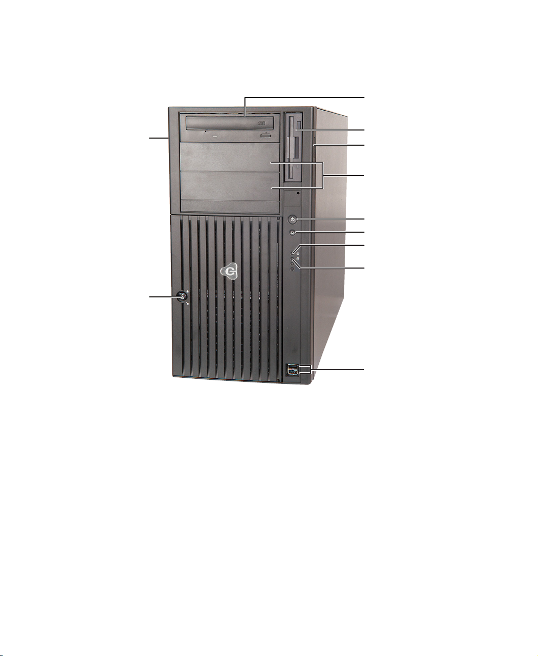
Front
CD drive
Cover release
latch
Key lock
Diskette drive
Cover release
latch
Additional drive
bays
Power button
Reset button
Power indicator
Hard drive indicator
USB ports
2
www.gateway.com
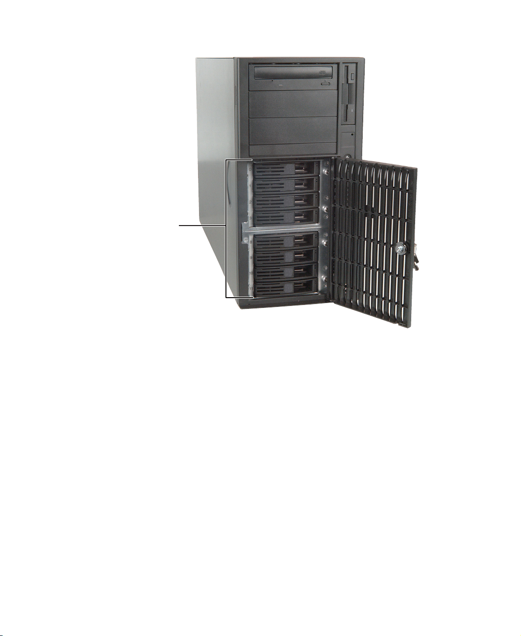
Hot-swap drives
Front
www.gateway.com
3
Chapter 1: Checking Out Your Gateway Server
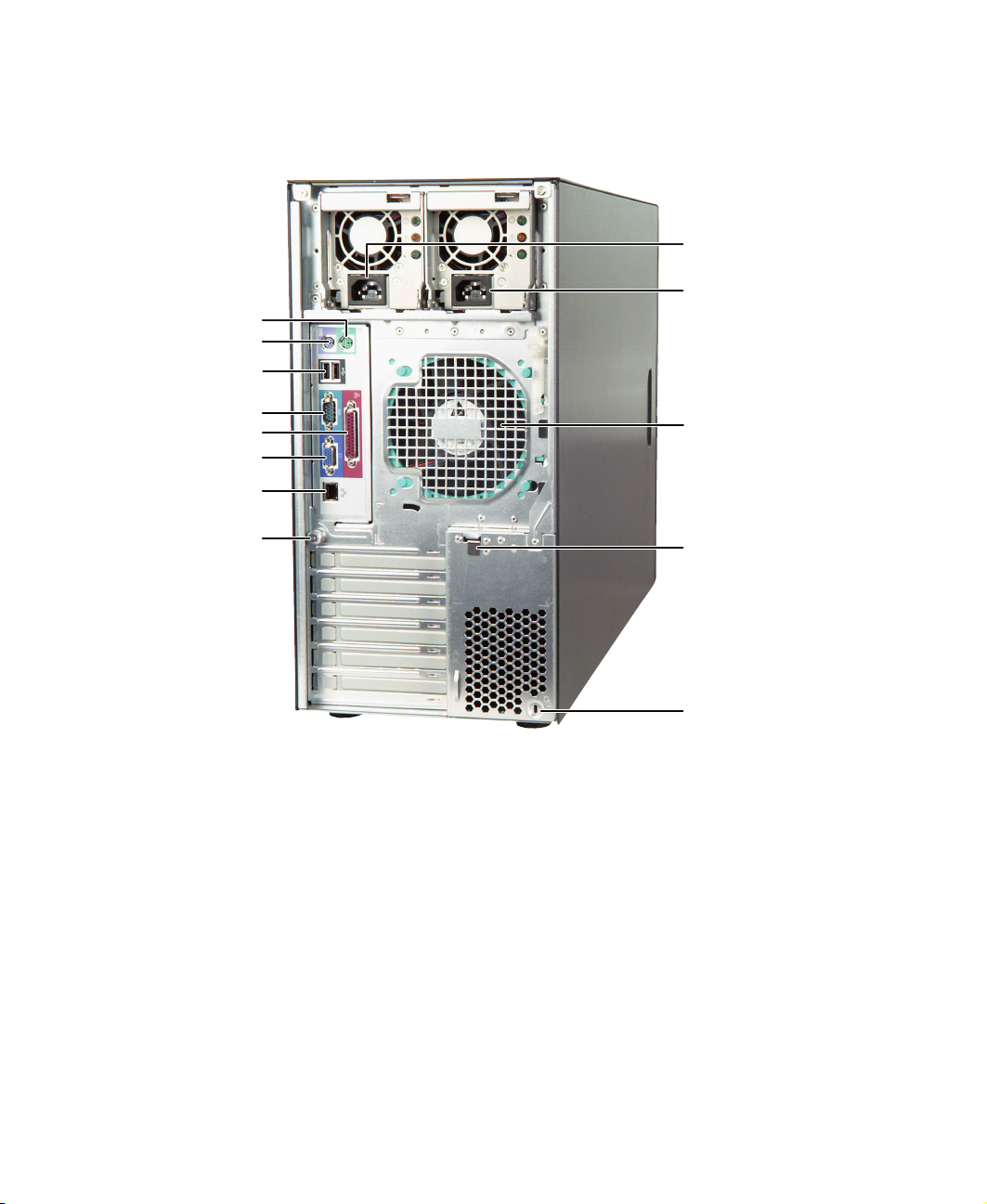
Back
Mouse port
Keyboard port
USB ports
Power connector
Power connector
Serial port
Parallel port
Monitor port
LAN jack
(RJ-45)
System board
thumbscrew
Rear fan
Card retention
cover lever
Kensington
lock slot
4
www.gateway.com
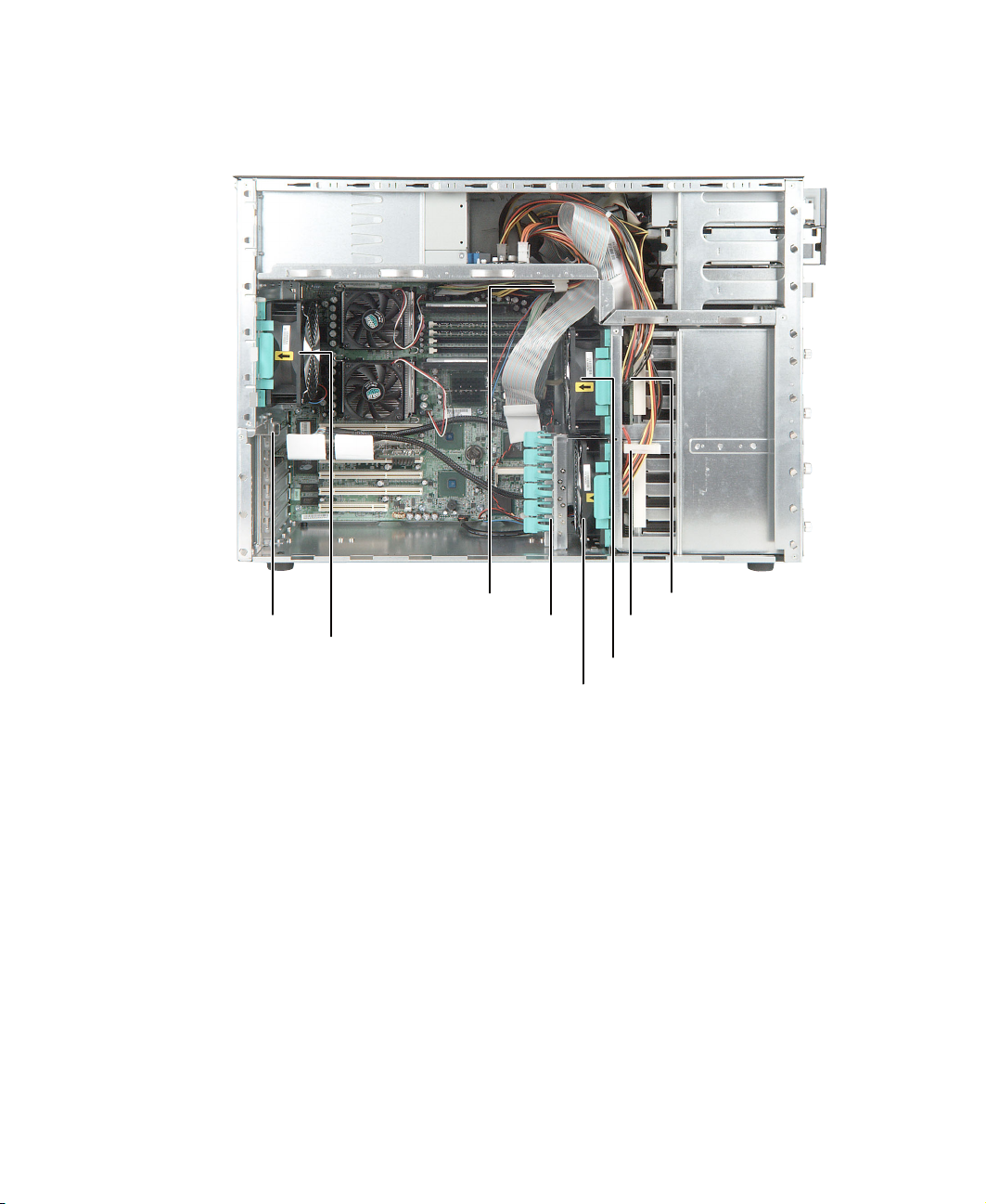
Interior
Interior
Card retention
cover release
latch
Rear fan
Cable clip
Full-length card
retention clip
www.gateway.com
SCSI backplane
Cable clip
Hot-swap bay fan
PCI card fan
5
Chapter 1: Checking Out Your Gateway Server
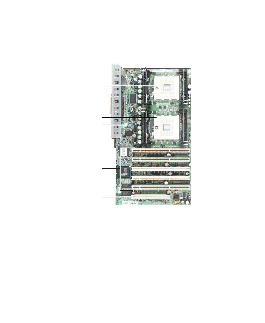
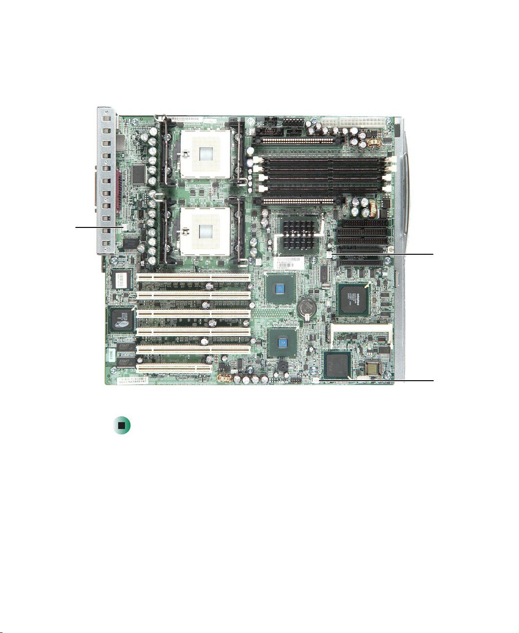
System board
Left side
Processor 1
Processor 2
Rear fan
connector
64-bit PCI card
32-bit PCI card
6
slots
slot
www.gateway.com
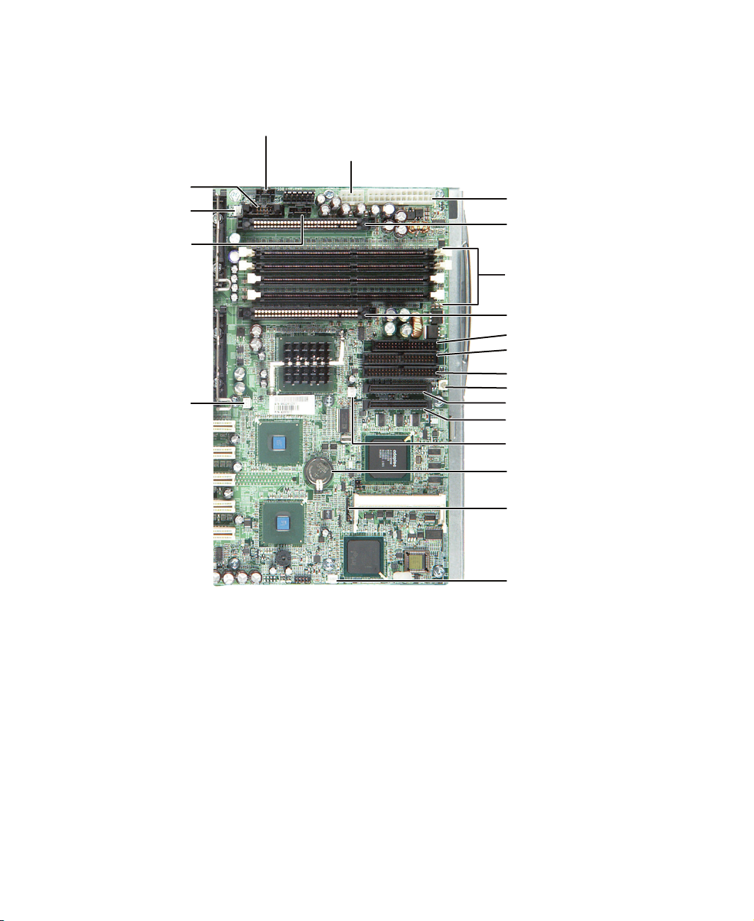
Right side
Processor 1
fan connector
Front panel
connector
SCSI
manageability
connector
Processor 2
fan connector
System board
Power supply manageability connector
Auxiliary power connector
Main power connector
Voltage regulator slot 1
Memory module slots
Voltage regulator slot 2
Diskette drive connector
Primary IDE connector
Secondary IDE connector
Intrusion switch connector
SCSI 2 connector
SCSI 1 connector
Hot-swap bay fan
connector
CMOS battery
www.gateway.com
Configuration jumper JP7
PCI card fan connector
7

Chapter 1: Checking Out Your Gateway Server
Getting Help
In addition to your operating system’s documentation, you can use the
following information resources to help you use your server.
Server Companion CD
Use the Server Companion CD to access file utilities, Windows 2000 Server
drivers, and documentation for your server and its components. For more
information, see Using Your Server Companion CD.
Gateway Web site
Gateway provides a variety of information on its Web site to help you use your
server.
Visit the Gateway Web site at support.gateway.com
■ Technical documentation and product guides
■ Technical tips and support
■ Updated hardware drivers
■ Order status
■ Frequently asked questions (FAQs)
for:
8
www.gateway.com

Setting Up Your
Server
Read this chapter to learn how to:
■ Use your server safely
■ Start and turn off your server
■ Restart (reboot) your server
■ Set up the operating system
2
9

Chapter 2: Setting Up Your Server
Setting up the hardware
To make sure that your working environment is safe:
■ Use a clean, dry, flat, stable surface for your server. Allow at least 6 inches
at the rear of the server for cabling and air circulation.
■ Use the instructions on your server’s setup poster to set up your hardware.
■ Use a grounded (three-prong) surge protector. A surge protector helps
protect against AC power fluctuations. For additional protection from
power outages, we recommend that you use an uninterruptible power
supply (UPS).
Warning Your server comes with a 3-wire AC power cords fitted with
the correct plug style for your region. If these plugs do not
match the connector on your surge protector, UPS, or wall
outlet, do not attempt to modify the plugs in any way. Use
a surge protector, UPS, or wall outlet that is appropriate
for the supplied AC power cords.
■ Avoid subjecting your server to extreme temperature changes. Do not
expose your server to direct sunlight, heating ducts, or other
heat-generating objects. Damage caused by extreme temperatures is not
covered by your warranty. As a general rule, your server is safest at
temperatures that are comfortable for you.
■ Keep your server and magnetic media away from equipment that
generates magnetic fields, such as unshielded stereo speakers. Strong
magnetic fields can erase data on both diskettes and hard drives. Even a
telephone placed too close to the server may cause interference.
Important Keep the server boxes and packing material in case you
need to send the server to Gateway for service. If you
return your server in different packaging, your warranty
may be voided.
Converting to a rackmount server
To convert your server to a rackmount configuration, see Installing Your Gateway
960 or 980 Server into a Rackmount Cabinet.
10
www.gateway.com

Protecting from power source problems
Protecting from power source
problems
Surge protectors, line conditioners, and uninterruptible power supplies can help
protect your server against power source problems.
Surge protectors
During a power surge, the voltage level of electricity coming into your server
can increase to far above normal levels and cause data loss or server damage.
Protect your server and peripheral devices by connecting them to a surge
protector, which absorbs voltage surges and prevents them from reaching your
server.
Warning High voltages can enter your server through both the
power cords, and the modem and network connections.
Protect your server by using a surge protector. If you have
a modem, use a surge protector that has the appropriate
type of modem jack. During an electrical storm, unplug
both the surge protector and the modem and network
cables.
When your purchase a surge protector:
■ Make sure that the surge protector meets the appropriate product safety
certification for your location, such as Underwriters Laboratories (UL).
■ Check the maximum amount of voltage the protector allows to pass
through the line. The lower the voltage that the protector allows to pass
through, the better the protection for your server.
■ Check the energy absorption (dissipation) rating. The higher the energy
absorption rating, the better the protection for your server.
■ Check for line-conditioner capabilities. A line conditioner smooths out
some of the normal line noise (small voltage fluctuations) of an electrical
supply.
www.gateway.com
11

Chapter 2: Setting Up Your Server
Line conditioners
A line conditioner protects your server from the small fluctuations in voltage
from an electrical supply. Most servers can handle this variation, called line
noise, without problems. However, some electrical sources include more line
noise than normal. Line noise can also be a problem if your server is located
near, or shares a circuit with, a device that causes electromagnetic interference,
such as a television or a motor.
Some surge protectors and uninterruptible power supplies include simple
line-conditioning capabilities.
Uninterruptible power supplies
Use an uninterruptible power supply (UPS) to protect your server from data loss
during a total power failure. A UPS uses a battery to keep your server running
temporarily during a power failure and lets you save your work and shut down
your server. You cannot run your server for an extended period of time while
using only the UPS. To buy a UPS, visit accessories.gateway.com
.
12
www.gateway.com
Starting your server
Before you start your server for the first time:
■ Make sure that the server and monitor are plugged into a power outlet or
surge protector and that the surge protector (if you are using one) is turned
on.
■ Make sure that all cables are connected securely to the correct ports and
jacks on the back of the server.
Warning When you connect peripheral devices to the server, make
sure that your server and devices are turned off and the
power cords are unplugged.
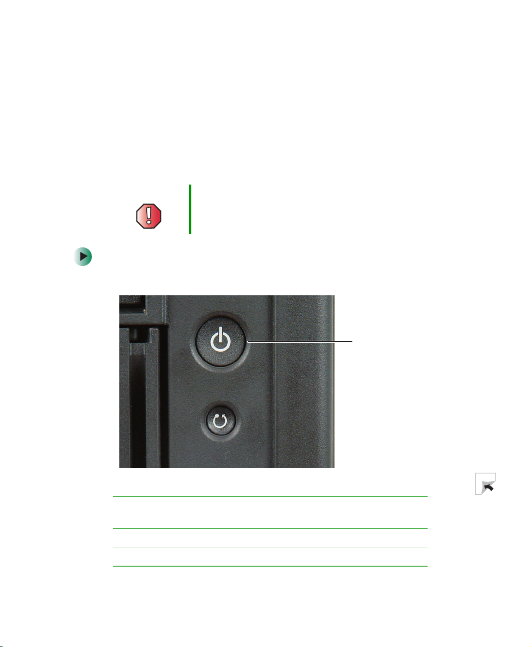
To start the server:
1 Press the power button.
Starting your server
When the power
indicator is...
Green The server is turned on.
Off The server is turned off.
It means...
www.gateway.com
Power button
13

Chapter 2: Setting Up Your Server
If nothing happens when you press the power button:
■ Make sure that the power cords are plugged in securely and that your
surge protector (if you are using one) is plugged in and turned on.
■ Make sure that the monitor is connected to the server, plugged into
the power outlet or surge protector, and turned on. You may also need
to adjust the monitor’s brightness and contrast controls.
2 The first time you turn on the server, any pre-installed operating system
may begin asking you for configuration settings. See your operating
system’s documentation for instructions on configuring advanced settings
for your specific network
To select which device your server boots from:
1 During server startup, press F10. The Boot menu opens.
2 Select the device you want to boot from. Common choices include:
■ Removable Dev. (Removable device)
■ ATAPI CDROM (CD drive)
■ Hard Drive
■ IBA GE NIC (Network boot)
Understanding the power-on self-test
When you turn on your server, the power-on self-test (POST) routine checks
the server memory and components. If POST finds any problems, the server
displays error messages. Write down any error messages that you see, then see
“Error messages” on page 83 and “Beep codes” on page 86 for troubleshooting
information.
14
www.gateway.com
Turning off your server
Turning off your server
Every time you turn off your server, first shut down the operating system. You
may lose data if you do not follow the correct procedure.
To turn off the server:
1 See the operating system’s documentation or online help for instructions
on shutting down the operating system. Whenever possible, you should
use the operating system’s shut down procedure instead of pressing the
power button.
2 If your server did not turn off automatically, press the power button. If
nothing happens when you press the power button, press and hold it for
five seconds and the server will turn off.
Warning The power button on the server does not turn off server
AC power. To remove AC power from the server, you must
unplug both AC power cords from the wall outlet or power
source. The power cords are considered the disconnect
device to the main (AC) power.
Warning If you routinely turn off your server (daily or weekly), do
not unplug the server or use the On/Off switch on the surge
protector. Regularly cutting off all power to your server may
cause the CMOS battery to fail prematurely.
www.gateway.com
15

Chapter 2: Setting Up Your Server
Setting up the operating system
If you ordered your server with the operating system already installed by
Gateway, it is completely installed and the basic settings are already configured.
See your operating system’s documentation for instructions on configuring
advanced settings for your specific network.
If you are installing an operating system because it was not already installed
by Gateway, see the appropriate installation guide for instructions.
16
www.gateway.com

Maintaining Your
Server
Read this chapter to learn how to:
■ Care for your server
■ Record the BIOS configuration
■ Manage your server and network
3
17

Chapter 3: Maintaining Your Server
Caring for your server
To extend the life of your server:
■ Be careful not to bump or drop your server.
■ When transporting your server, we recommend that you put it in the
original packaging materials.
■ Keep your server and magnetic media away from equipment that generates
magnetic fields.
■ Avoid subjecting your server to extreme temperatures. Do not expose your
server to heating ducts or other heat-generating objects. Damage caused
by extreme temperatures is not covered by your warranty. As a general rule,
your server is safest at temperatures that are comfortable for you.
■ Keep all liquids away from your server. When spilled onto server
components, almost any liquid can result in extremely expensive repairs
that are not covered under your warranty.
■ Avoid dusty or dirty work environments. Dust and dirt can clog the
internal mechanisms and can cause the server to overheat.
Cleaning your server
Keeping your server clean and the vents free from dust helps keep your server
performing at its best. Your server cleaning kit could include:
■ A soft, lint-free cloth
■ Glass cleaner
■ An aerosol can of air with a narrow, straw-like extension
■ Isopropyl alcohol
■ Cotton swabs
■ A tape drive cleaning cartridge (if a tape drive is installed)
■ A CD drive cleaning kit
18
www.gateway.com

Caring for your server
Cleaning tips
■ Always turn off your server and other peripheral devices before cleaning
any components.
Warning When you shut down your server, the power turns off, but
some electrical current still flows through your server. To
avoid possible injury from electrical shock, unplug the
power cords and all other cables connected to the server.
■ Use a damp, lint-free cloth to clean your server and other parts of your
server system. Do not use abrasive or solvent cleaners because they can
damage the finish on components.
■ Keep the cooling vents free of dust. With your server turned off and
unplugged, brush the dust away from the vents with a damp cloth, but
be careful not to drip any water into the vents.
Cleaning the keyboard
You should clean the keyboard occasionally by using an aerosol can of air with
a narrow, straw-like extension to remove dust and lint trapped under the keys.
If you spill liquid on the keyboard, turn off your server and turn the keyboard
upside down to let the liquid drain. Let the keyboard dry completely before
trying to use it again. If the keyboard does not work after it dries, you may
need to replace it. Keyboard damage resulting from spilled liquids is not covered
by your warranty.
Cleaning the screen
If your computer screen is a flat panel display, use only a damp, soft cloth to
clean it. Never spray water directly onto the screen.
Warning The computer screen is made of specially coated glass
and can be scratched or damaged by abrasive or
ammonia-based glass cleaners.
- OR -
If your computer screen is not a flat panel display, use a soft cloth dampened
with glass cleaner to clean the screen. Never spray cleaner directly onto the
screen.
www.gateway.com
19

Chapter 3: Maintaining Your Server
Cleaning the tape drive
If you use a tape drive to back up your files, regular maintenance will lengthen
the life of the drive. To maintain the drive’s reliability:
■ Clean the drive monthly with the cleaning cartridge included with
the drive.
■ Remove the tape from the drive whenever the drive is not in use.
20
www.gateway.com

Preparing for system recovery
Preparing for system recovery
If your system files are corrupted, you may not be able to start the server from
the hard drive. Startup diskettes are diskettes that let you start the server and
attempt to fix the problem. See your operating system’s documentation or
online help for instructions on creating startup diskettes.
Some operating systems also let you create an emergency repair diskette to back
up critical operating system files. See your operating system’s documentation
or online help for instructions on using an emergency repair diskette.
Recording the BIOS configuration
To help keep track of your custom changes to BIOS settings and to prepare for
system recovery, you should record your BIOS configuration after you have your
server set up and working.
To record your BIOS configuration:
1 Print the appendix for BIOS Settings in this guide.
2 Restart your server, then press F2 when the Gateway logo screen appears
during startup. The BIOS Setup utility opens.
3 Record the BIOS settings on your printout.
www.gateway.com
21

Chapter 3: Maintaining Your Server
System administration
Gateway Server Manager
Gateway Server Manager lets you manage multiple computers on a Windows
network from a single window, then implement commands and policies across
the network with a single action. With Gateway Server Manager, you can run
system management tasks which are triggered by certain events or conditions.
Printed documentation comes with the Gateway Server Manager CD. You can
find additional documentation in the program’s online help.
Server security
To prevent unauthorized use of the server, you can set BIOS startup passwords.
Using BIOS security passwords
Set up a supervisor password to prevent unauthorized access to the BIOS Setup
utility. After you create a supervisor password, you can set up a user password
to prevent unauthorized access to the server. You can:
■ Enter either password to finish starting the server.
■ Enter the supervisor password to access the BIOS Setup utility.
For information about resetting BIOS passwords, see “Resetting BIOS
passwords” on page 79.
To set the BIOS security passwords:
1 Restart your server, then press F2 when the Gateway logo screen appears
during startup. The BIOS Setup utility opens.
2 Select the Security menu.
22
www.gateway.com

System administration
3 Select the password to set according to the following table.
Option Description
Supervisor password To control access to system configuration, set a
supervisor password. Using a supervisor password lets
you make changes to any setting in the BIOS.
Passwords can be cleared. To clear the passwords, see
“Resetting BIOS passwords” on page 79.
User password The supervisor password must be set up before a user
password can be set. To control access to the server, set
a user password. The supervisor can set the level of
access granted to the user password. The user password
access levels are:
■
No Access. User cannot access the BIOS Setup utility.
■
Limited. User can change only the date and time.
■
View Only. User can see all settings, but cannot
change them.
■
Full. User can change every setting except the
supervisor password.
Passwords can be cleared. To clear the passwords, see
“Resetting BIOS passwords” on page 79.
4 Type the password and press ENTER, then type it again and press ENTER.
5 Save your changes and exit the BIOS Setup utility.
www.gateway.com
23

Chapter 3: Maintaining Your Server
Using your Server Companion CD
You can use your Server Companion CD to:
■ Install hardware drivers
■ Install programs
■ View server documentation
Instructions for using the CD are provided in Using Your Server Companion CD.
24
www.gateway.com

Installing
Components
Read this chapter to learn how to:
■ Open and close the server case
■ Install drives
■ Install expansion cards and memory modules
■ Install processors and replace voltage regulators
■ Check and replace the power supplies
■ Replace the SCSI backplanes
■ Replace the system board
■ Replace case fans
■ Replace the CMOS battery
You must open your server case to install components. If
you are not comfortable with these procedures, get help
from a more experienced computer user or computer
service technician, or contact Gateway Technical Support.
4
25

Chapter 4: Installing Components
Preparing to install components
Selecting a place to work
Work on your server in an area that:
■ Is clean (avoid dusty areas)
■ Is a low-static environment (avoid carpeted areas)
■ Has a stable surface on which to set your server
■ Has enough room to place all of your server parts
■ Is near a grounded outlet so you can test your server after installation
■ Is near a telephone (in case you need help from Gateway Technical
Support). The telephone must be directly connected to a telephone jack
and cannot be connected to your server.
Gathering the tools you need
Some tools and supplies that you may need to work on your server are:
■ A notebook to take notes
■ A Phillips screwdriver
■ A small flat-blade screwdriver
■ Small containers to store various types of screws
■ A grounding wrist strap (available at most electronic stores)
26
www.gateway.com

Preventing static electricity discharge
Preventing static electricity
discharge
The components inside your server are extremely sensitive to static electricity,
also known as electrostatic discharge (ESD).
Warning ESD can permanently damage electrostatic
discharge-sensitive components in the server. Prevent
ESD damage by following ESD guidelines every time you
open the server case.
Warning To avoid exposure to dangerous electrical voltages and
moving parts, turn off your server and unplug the power
cords and modem cable before opening the server case.
Before working with server components, follow these guidelines:
■ Turn off the server, then unplug the power cords and all other cables.
■ Press the power button to drain any residual power from the server.
■ Wear a grounding wrist strap (available at most electronics stores) and
attach it to a bare metal part of the server. You can also touch a bare metal
surface on the back of the server with your finger.
Warning To prevent risk of electric shock, do not insert any object
into the vent holes of the power supply.
■ Avoid static-causing surfaces such as carpeted floors, plastic, and packing
foam.
■ Avoid working on the server when your work area is extremely humid.
■ Remove components from their antistatic bags only when you are ready
to use them. Do not lay components on the outside of antistatic bags
because only the inside of the bags provide electrostatic protection.
■ Always hold expansion cards by their edges or their metal mounting
brackets. Avoid touching the edge connectors and components on the
cards. Never slide expansion cards or components over any surface.
www.gateway.com
27

Chapter 4: Installing Components
Opening the server case
Because the components inside your server are extremely sensitive to static
electricity, make sure that you follow the instructions at the beginning of this
chapter to avoid static electricity damage.
Warning For correct cooling and air flow, always reinstall the side
panel and the air duct (if included) before you turn on the
server. Operating the server without the cover in place can
damage server components.
To open the server case:
1 Follow the instructions in “Preventing static electricity discharge” on
page 27.
2 Turn off the server, then unplug the power cords and all other cables
connected to the server.
Warning This server has two power cords. To disconnect internal
AC power, you must unplug both power cords.
28
www.gateway.com

3 Unlock the front cover.
Opening the server case
Release latch
Lock
Release latch
4 Press the two front cover release latches, then pull the cover away from
the server.
5 For more stability, place the server on its side.
www.gateway.com
29

Chapter 4: Installing Components
6 Loosen the three captive thumbscrews that secure the side panel to the
server.
7 Slide the side panel toward the front of the case about ½ inch, then lift
the panel away from the server.
Thumbscrews
30
www.gateway.com

Opening the server case
8 If your server has an air duct, pull the tab on the right until it releases the
duct from the server, then lift the duct away from the server.
www.gateway.com
31

Chapter 4: Installing Components
Closing the server case
To close the server case:
1 For more stability, place the server on its side.
2 Make sure that all of the internal cables are arranged inside the case so
they will not be pinched when you close the case.
3 Replace the air duct if one came with your server.
4 Align the side panel’s top and bottom tabs into the case notches, then slide
the side panel toward the back of the case until the back of the side panel
is flush with the back of the case.
5 Tighten the three captive thumbscrews that secure the front of the cover
to the server case.
Thumbscrews
32
6 Set the case upright.
www.gateway.com

Closing the server case
7 Align the notch in the bottom of the front cover with the rail on the front
of the case, then swing the cover against the case.
8 Lock the front cover.
9 Reconnect the power cords and all other cables.
www.gateway.com
33

Chapter 4: Installing Components
Installing drives
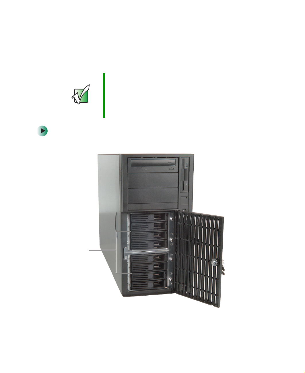
Your server’s basic configuration includes one CD drive and one 3.5-inch
diskette drive. Your server also has two additional 5.25-inch drive bays.
Your server can have up to eight SCSI hard drives in the hot-swap bay behind
the front access door.
CD drive
Diskette drive
5.25-inch drive bay
5.25-inch drive bay
Hot-swap
bays
As you prepare to install drives, remember:
■ Do not use the top 5.25-inch drive bay for drives which have electronic
components exposed on the top. Drive mounting rails at the top of the
bay may damage any exposed electronic components.
■ Before you install a drive, see the drive’s documentation for information
on configuring the drive, setting drive jumpers, and attaching cables.
■ IDE hard drives can be configured as single, master, slave, or cable-select.
IDE CD drives can be configured as master, slave, or cable-select.
34
www.gateway.com

■ If cable-select is available (drive assignments will be marked on the
cable), the IDE cable assigns the master/slave positions to the drives
it connects. You can override these assignments using the jumpers on
the drives.
■ If cable-select is not available and only one drive is attached to an IDE
controller cable, configure the drive as master if it is a CD drive. If
two drives of any type are attached to the cable, configure one as
master and one as slave.
■ You may need to configure the drives you install using the BIOS Setup
utility. Press F2 at startup to open the BIOS Setup utility.
Installing an IDE drive
Use these instructions to install or replace a diskette, CD, hard drive, or tape
drive.
To install a 5.25-inch drive:
1 Follow the instructions in “Preventing static electricity discharge” on
page 27.
Installing drives
2 Follow the instructions in “Opening the server case” on page 28.
www.gateway.com
35

Chapter 4: Installing Components
3 If you are replacing a drive, go to Step 7.
- OR -
If you are adding a new drive, press and hold the two locking clips against
the bay’s 3.5-inch drive adapter, then pull it out of the server.
36
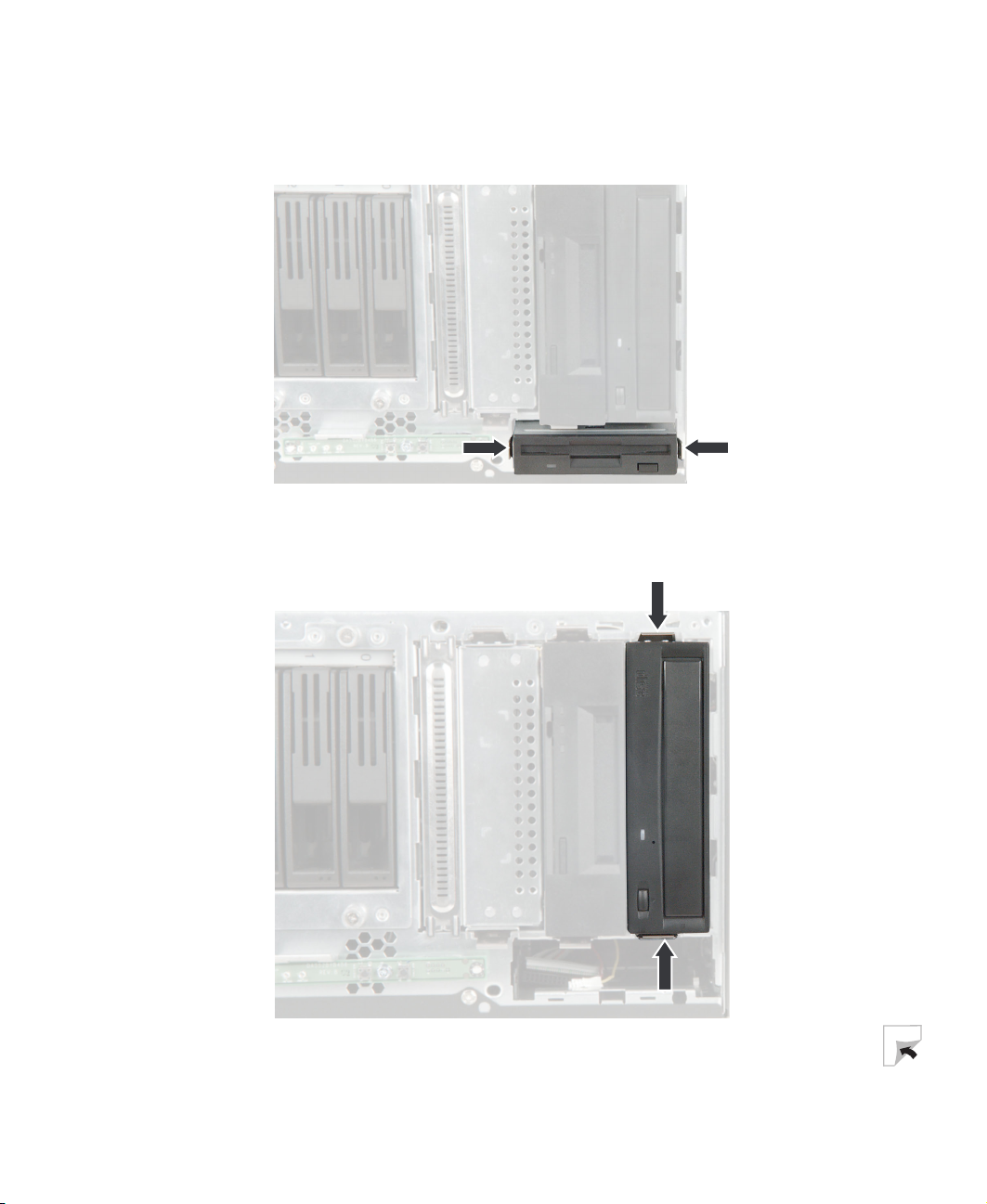
4 Press the drive bay face plate release tabs inward, then pull the face plate
away from the front cover.
www.gateway.com

Installing drives
5 If you are adding a 3.5-inch hard drive, use the screws that came with your
IDE hard drive to secure the drive to the 3.5-inch drive adapter.
IDE hard drive screws
- OR -
IDE hard drive screws
www.gateway.com
37

Chapter 4: Installing Components
If you are replacing the 3.5-inch drive adapter with a new 5.25-inch drive,
remove the two screws connecting each mounting rail to the adapter,
remove the rails, then attach the rails to the sides of your new drive.
Mounting rail
screw
Mounting rail
screw
Two screws for mounting the rail onto CD and diskette drives are stored
on each rail. Screws for mounting onto most tape drives are stored in the
case near the full-length card retention clips.
Mounting rail
screw
Mounting rail
screw
38
Tape drive
screws
6 Go to Step 11.
7 If you are replacing a drive, disconnect the old drive’s cables.
www.gateway.com
Installing drives
8 If you are removing a drive from one of the top two bays, first remove
the 3.5-inch diskette drive so you can reach the 5.25-inch drive’s release
latch.
9 Press the old drive’s release latches against the drive, then pull the drive
out of the bay.
www.gateway.com
39

Chapter 4: Installing Components
10 Remove the screws that secure the mounting rails to the old drive, then
use the screws to attach the rails to the new drive.
Screws for mounting the rails onto most tape drives are stored in the case
near the full-length card retention clips.
Screw
Screw
Tape drive
screws
11 Set any jumpers on the new drive. See the drive’s documentation for further
instructions.
12 Slide the new drive into the drive bay until the drive rails snap into place.
40
www.gateway.com

13 Connect the drive cables. For more information, see the drive’s
documentation.
14 Follow the instructions in “Closing the server case” on page 32.
Installing drives
www.gateway.com
41
Chapter 4: Installing Components
Installing a SCSI hard drive
Use this procedure to add or replace hard drives in the hot-swap bay. Your server
supports up to eight 1-inch high 3.5-inch SCA SCSI hard drives. You can
purchase additional SCSI drives through your Gateway sales representative.
Important The numbers on the left side of the hot-swap bay identify
the SCSI ID of each drive. Install the topmost drives first.
Gateway tests and verifies the operation and compatibility
of the drives it sells. Especially in a hot-swap or
mission-critical environment, additional or replacement
drives must conform to Gateway standards.
To install a hard drive:
1 Unlock the front cover’s lock, then swing the hot-swap bay door open.
42
Hot-swap
bays
www.gateway.com

Installing drives
2 If a drive has failed, determine which drive has failed by running storage
console software. Match the software’s SCSI ID for the failed drive with
the SCSI ID number to the left of the hot-swap bays.
3 Pull the drive tray’s lever away from the server, then pull the tray straight
out of the server.
Caution Before you remove a failed drive, use the appropriate
software and utilities installed on the server to stop all
activity on the failed drive. Instructions for using the
software are provided by the software manufacturer.
Failure to do so may destroy the data on the drive.
4 If you are replacing a hard drive, remove the four screws that secure the
hard drive to the drive tray, then remove the drive from the tray.
Screw
Screw
Screw
Screw
- OR -
www.gateway.com
43

Chapter 4: Installing Components
If you are adding a new drive, remove the bag taped to the inside of the
drive tray, then remove the screws from the bag.
5 Line up the screw holes in the new drive with the holes in the side of the
drive tray, then secure the drive to the tray with the four screws you
removed in Step 4.
44
6 Make sure that the tray’s release lever is open, then slide the new drive
into the empty hot-swap bay.
7 Close the drive’s release lever.
www.gateway.com
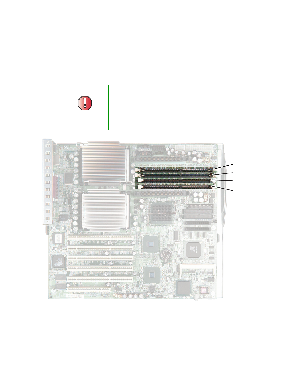
Installing memory
When you upgrade your server memory, make sure that you install the correct
type of memory module for your server. Your server uses PC2100 DDR SDRAM
registered ECC DIMM memory. The following illustration shows the location
of the memory modules on the system board.
Warning Modules must be installed in identical pairs. Use only
PC2100 DDR SDRAM registered ECC DIMM memory
modules.
Install memory first into slots 1 and 2, then into slots 3
and 4. If you have memory installed incorrectly, your server
will not start up.
Installing memory
DIMM slot 1
DIMM slot 2
DIMM slot 3
www.gateway.com
DIMM slot 4
45

Chapter 4: Installing Components
To install or replace memory:
1 Follow the instructions in “Preventing static electricity discharge” on
page 27.
2 Follow the instructions in “Opening the server case” on page 28.
3 Pull the plastic tabs away from the sides of the memory module slot. If
you are replacing a memory module, remove the old module.
4 Align the notch on the new module with the notch in the memory module
slot and press the module firmly into the slot. The tabs on the sides of
the memory slot should secure the memory module automatically.
46
5 Follow the instructions in “Closing the server case” on page 32.
6 Turn on the server. Make sure that the server turns on and that the
operating system loads completely.
7 Restart your server and open the BIOS Setup utility. Verify the System
Memory
listed in the Main menu.
www.gateway.com

Installing PCI expansion cards
Installing PCI expansion cards
Your server uses the PCI-X bus. Use the following chart to determine the PCI slot
you should install your expansion card into.
PCI slot Description
1 Always runs at 64-bit/66 MHz. Supports 32-bit and 64-bit cards, 3.3 V or universal.
2-3 Paired slots. When only one card is installed in a slot of this pair, the slot can run
at 64-bit/133 MHz. When two 64-bit/100 MHz cards are installed in this pair, the slot
can run at 64-bit/100 MHz. When cards of different speeds are installed in this pair,
each slot runs at the slowest of the two speeds. Supports both 32-bit and 64-bit
cards, 3.3 V or universal.
4-5 Same as slots 2-3.
6 Always runs at 32-bit/33 MHz. Supports 5 V or universal cards.
PCI slot 1
PCI slots 2-3
PCI slots 4-5
PCI slot 6
www.gateway.com
47

Chapter 4: Installing Components
To replace, add, or reseat a PCI expansion card:
1 Follow the instructions in “Preventing static electricity discharge” on
page 27.
2 Follow the instructions in “Opening the server case” on page 28.
3 If you are replacing a card, disconnect any cables that are attached to the
old card.
4 If you are removing a full-length card, pull back on the card retention clip
that secures the end of the card.
- OR -
If you are adding a full-length card to an empty expansion slot, pull back
on the card retention clip for that slot.
48
www.gateway.com

Installing PCI expansion cards
5 Pull the card retention cover’s release lever, then swing the retention cover
away from the expansion cards.
Release lever
Card retention
cover
6 If you are replacing a card, remove the old expansion card. You can slightly
seesaw the card end-to-end to loosen the card, but do not bend the card
sideways.
Warning Do not touch the contacts on the bottom part of the
expansion card. Touching the contacts can cause
electrostatic damage to the card.
7 Press the new card into the expansion slot. You can slightly seesaw the
card end-to-end to help insert the card, but do not bend the card sideways.
www.gateway.com
49

Chapter 4: Installing Components
8 Push the card retention cover against the expansion cards until the
retention cover clicks into place under the release lever.
Release lever
Card retention
- OR -
Press on the card retention cover lever on the back of the server until the
lever is flush with the back of the case.
cover
50
9 If you are installing a full-length card, press down on the card retention
clip to secure the end of the card.
www.gateway.com

Installing PCI expansion cards
10 Connect any cables to the card. For more information, see the instructions
in the card’s documentation.
11 Follow the instructions in “Closing the server case” on page 32.
12 See the card’s documentation for software installation instructions.
www.gateway.com
51

Chapter 4: Installing Components
Installing a processor
The server is compatible with Intel® Xeon processors with 512 KB cache. The
server automatically detects the processors each time you turn on the server.
Whenever you install new processors, you should first install the most current
version of the BIOS. For more information, see “Updating the BIOS” on page 77.
Important You must have a processor in the upper (processor 1) slot,
or your server will not start.
If you are upgrading your server from one processor to two,
you may need to reconfigure your operating system so it
can recognize the additional processor. For more
information, see your operating system’s documentation.
Warning A heat sink must be installed on the processor. Installing
a processor without a heat sink could damage the
processor.
Warning Processors and heat sinks may be hot if the computer has
been running. Also, there may be sharp edges on the heat
sinks. Consider wearing protective gloves.
To replace a processor:
1 Install the most current BIOS version. For more information, see “Updating
the BIOS” on page 77.
2 Follow the instructions in “Preventing static electricity discharge” on
page 27.
3 Follow the instructions in “Opening the server case” on page 28.
Tips & Tricks To make removing the heat sinks easier, first remove the
52
voltage regulators, PCI expansion cards, and rear fan. For
more information, see “Installing a voltage regulator” on
page 56, “Installing PCI expansion cards” on page 47, and
“Replacing a fan” on page 69.
www.gateway.com

Installing a processor
4 If your server has a passive heat sink, press down on the heat sink locking
lever on each side, push them slightly away from the heat sink, then lift
the levers out of the way.
- OR -
If your server has a heat sink with a fan, press down on the heat sink
locking lever on each side, push them slightly away from the heat sink,
then lift the levers out of the way. Unplug the heat sink’s fan from its
connector on the system board.
www.gateway.com
53

Chapter 4: Installing Components
5 Remove the heat sink.
Important The heat sink mounting paste may harden over time and
6 Press down on the processor locking lever, push it slightly away from the
processor, then rotate the lever a full 135° to release the processor.
hold the heat sink securely to the processor. If removing
the heat sink also pulls the processor out of the processor
socket, the processor should still be undamaged. Rotate
the processor locking lever out of the way and continue
with the procedure.
7 Remove the old processor.
8 Install the new processor into the processor socket. Make sure that:
■ The processor release lever is open all the way (135° from the closed
position)
■ The triangular arrow on the corner of the processor aligns with the
triangular hole on the corner of the processor socket
■ The processor is flush with the socket.
Important If you install two processors onto the system board, the
processors can be different speeds. Both processors will
run at the lower of the two speeds.
9 Press the processor locking lever down until it clicks into place.
10 Apply thermal grease to the top of the processor, if necessary.
11 Place the heat sink on the processor, then press the heat sink locking levers
down until they click into place.
54
www.gateway.com

12 If your heat sink has a fan, plug the fan into the connector on the system
Processor 1
fan connector
Processor 2
fan connector
Installing a processor
board next to the heat sink.
13 If you have installed a new processor into the lower (processor 2) slot for
the first time, you also need to install a voltage regulator for the processor.
If you ordered the processor from Gateway, it came with a new voltage
regulator. For instructions on installing a voltage regulator, see “Installing
a voltage regulator” on page 56.
Warning Only one voltage regulator should be installed for each
processor.
14 Follow the instructions in “Closing the server case” on page 32.
www.gateway.com
55

Chapter 4: Installing Components
Installing a voltage regulator
To install a voltage regulator:
1 Follow the instructions in “Preventing static electricity discharge” on
page 27.
2 Follow the instructions in “Opening the server case” on page 28.
3 If you are installing a new voltage regulator, go to Step 5.
- OR -
If you are replacing a voltage regulator, on each end of the voltage regulator
support bracket, pinch the sides together, then lift the bracket away from
the server. You may need to first remove a heat sink or some memory
modules in order to access the sides of the support bracket.
56
4 Lift the voltage regulator away from the system board.
5 Insert the new voltage regulator into the voltage regulator slot, then replace
the support bracket.
6 If you removed a heat sink or some memory modules in Step 3, replace
them.
7 Follow the instructions in “Closing the server case” on page 32.
www.gateway.com

Replacing the power supply
Replacing the power supply
Your server uses hot-swappable redundant power supplies. If one of the two
power supplies fails, the other power supply supports the server while you
replace the failed power supply. You do not need to turn off the server or
disconnect peripheral devices to replace a failed power supply.
Warning The power supplies in this server contains no
user-serviceable parts. Only a qualified computer
technician should service the power supplies.
Your server comes with 3-wire AC power cords fitted with
the correct plug style for your region. If this plug does not
match the connector on your surge protector, UPS, or wall
outlet, do not attempt to modify the plug in any way. Use
a surge protector, UPS, or wall outlet that is appropriate
for the supplied AC power cords.
www.gateway.com
57
Chapter 4: Installing Components
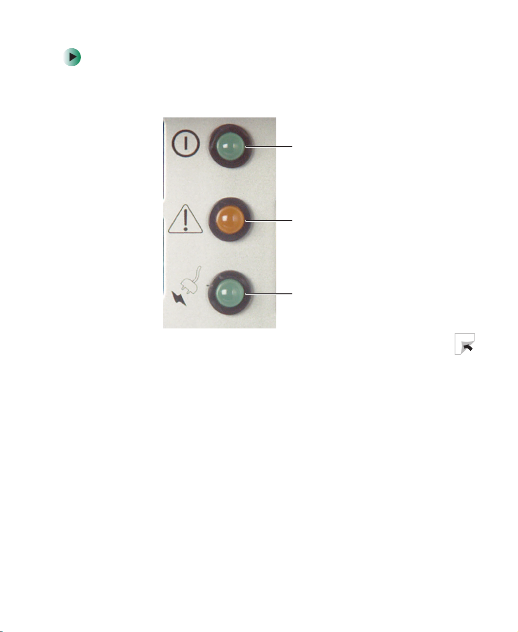
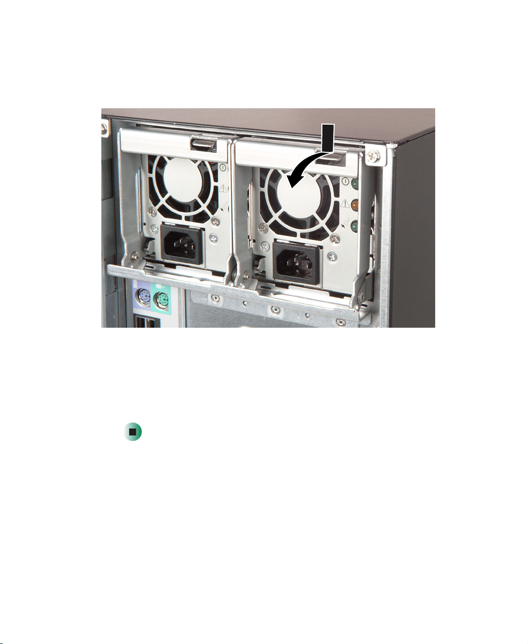
To replace the power supply:
1 Examine the LED indicators on the back of each power supply to identify
the failed power supply. The power supply has failed if the center LED
indicator is on.
Server is
turned on
Fault in power
supply
(center LED)
Power supply is
connected to
AC power source
58
www.gateway.com
Replacing the power supply
2 Unplug the power cord from the failed power supply.
3 While pressing the power supply’s lever release latch, pull the lever away
from the server.
4 Pull the power supply straight out of the server.
5 Slide the new power supply into the power supply bay as far as it will go,
then swing the lever up until it snaps into place.
6 Plug the power cord into the new power supply. The new power supply
is ready if the bottom green LED is on and the top LED is on or blinking.
www.gateway.com
59

Chapter 4: Installing Components
Replacing the SCSI backplane
Your server has two hot-swap cages that can each hold four SCSI drives. Each
hot-swap cage is connected to a SCSI backplane. The pictures in this procedure
show replacing the upper SCSI backplane. The other backplane can be replaced
in the same manner.
To replace the SCSI backplane:
1 Follow the instructions in “Preventing static electricity discharge” on
page 27.
2 Follow the instructions in “Opening the server case” on page 28.
3 Remove the fan nearest the SCSI backplane. For instructions, see
“Replacing a fan” on page 69.
4 Remove each of the drives from the hot-swap cage, and note the location
of each drive. For instructions, see “Installing a SCSI hard drive” on
page 42.
5 Loosen the four captive thumbscrews on the front of the hot-swap cage.
Thumb-
screws
60
Thumbscrews
www.gateway.com

Replacing the SCSI backplane
6 Slide the hot-swap cage out about two inches from the case.
www.gateway.com
61

Chapter 4: Installing Components
7 From inside the case, remove the power, SCSI, and manageability cables
from the backplane. The manageability cable connector is visible after
removing the SCSI and power cables.
62
8 Remove the hot-swap cage completely from the server.
www.gateway.com

Replacing the SCSI backplane
9 Loosen the captive thumbscrew that secures the backplane to the hot-swap
cage.
Thumbscrew
www.gateway.com
63

Chapter 4: Installing Components
10 Slide the backplane up slightly, then lift it away from the hot-swap cage.
11 Place the new backplane onto the hot-swap cage, then tighten the
thumbscrew.
12 Slide the hot-swap cage part-way into the hot-swap bay. Make sure that
the side of the cage marked “Top” is oriented toward the top of the server
case.
13 Reconnect the power, SCSI, and manageability cables to the backplane.
14 Slide the hot-swap cage all the way into the hot-swap bay, then tighten
the four thumbscrews.
64
www.gateway.com

Replacing the SCSI backplane
15 Reinstall the fan.
16 Install each of the drives back into the hot-swap cage. Make sure that you
replace the drives in the correct order by referring to your notes from
Step 4.
17 Follow the instructions in “Closing the server case” on page 32.
www.gateway.com
65

Chapter 4: Installing Components
Replacing the system board
To replace the system board:
1 Follow the instructions in “Preventing static electricity discharge” on
page 27.
2 Follow the instructions in “Opening the server case” on page 28.
3 Remove the memory modules. For more information, see “Installing
memory” on page 45.
4 Remove all of the expansion cards. For more information, see “Installing
PCI expansion cards” on page 47.
5 Remove the heat sinks and processors. For more information, see
“Installing a processor” on page 52.
6 If your new system board does not include heat sink mounting brackets,
remove the heat sink brackets from your old system board by removing
the eight screws that secure them to the board.
7 Remove the voltage regulators. For more information, see “Installing a
voltage regulator” on page 56.
66
8 Disconnect the power, data, and fan cables from the system board, noting
their locations and orientation. (You will reconnect the cables after you
install the new board.)
9 Remove the rear fan to provide more space for removing the system board.
For more information, see “Replacing a fan” on page 69.
www.gateway.com

Replacing the system board
10 Remove the system board tray’s thumbscrew on the back of the case.
System board
tray thumbscrew
11 Slide the tray toward the front of the case. If the tray is difficult to move,
push on the rear port panel for added leverage.
www.gateway.com
67

Chapter 4: Installing Components
12 Lift the tray away from the case.
13 Insert the new system board tray into the case, then slide the tray toward
the back of the case.
14 Tighten the system board tray thumbscrew on the back of the case.
15 Reinstall the memory, processors, voltage regulators, and fans.
16 Connect the power and data cables.
17 Reinstall the expansion cards. For more information, see “Installing PCI
expansion cards” on page 47.
18 Follow the instructions in “Closing the server case” on page 32.
19 Turn on your server.
20 Press F2 when the Gateway logo screen appears during startup. The BIOS
Setup utility opens.
21 Check BIOS settings to make sure that they detect the server’s new
hardware, then save your changes (if any) and close the BIOS Setup utility.
68
www.gateway.com

Replacing a fan
The pictures in this procedure show the hot-swap bay fan. All case fans can be
replaced in the same manner.
Important Make sure that you replace a fan with an identical
replacement fan. The arrow on each fan indicates the
direction of its air flow, and the arrow should point toward
the rear of the case.
To replace a fan:
1 Follow the instructions in “Preventing static electricity discharge” on
page 27.
2 Follow the instructions in “Opening the server case” on page 28.
3 Unplug the fan from the system board.
4 While pressing the locking clip, slide the fan away from the system board,
then pull it away from the case.
Replacing a fan
www.gateway.com
System board tray
thumbscrew
69
Chapter 4: Installing Components
5 Insert the new fan’s mounting posts into the fan mounting slots, then slide
the fan down until it snaps into place.
6 Reconnect the fan to the system board.
Rear fan
connector
Hot-swap
bay fan
connector
70
PCI fan
connector
7 Follow the instructions in “Closing the server case” on page 32.
www.gateway.com

Replacing the CMOS battery
Replacing the CMOS battery
If the server clock does not keep time or the settings in the BIOS Setup utility
are not saved when you turn off the server, replace the CMOS battery with an
equivalent battery.
Warning Danger of explosion if battery is incorrectly replaced.
Replace only with the same or equivalent type
recommended by the manufacturer. Dispose of used
batteries following the manufacturer’s instructions.
To replace the battery:
1 Print the appendix for BIOS Settings in this guide.
2 Open the BIOS Setup utility by following the instructions in “Opening the
BIOS Setup utility” on page 76.
3 Record the BIOS settings on your printout, then close the utility.
4 Turn off your server, then follow the instructions in “Preventing static
electricity discharge” on page 27.
5 Follow the instructions in “Opening the server case” on page 28.
www.gateway.com
71

Chapter 4: Installing Components
6 Locate the old battery on the system board and note its orientation. You
will need to install the new battery the same way.
72
Battery
www.gateway.com

Replacing the CMOS battery
7 Push the battery retention clip away from the battery until the battery lifts
up. You can use a screwdriver to help lift the battery.
8 Remove the old battery.
9 Make sure that the positive (+) side of the new battery is facing up, then
press the new battery into the socket until it snaps into place.
10 Follow the instructions in “Closing the server case” on page 32.
11 Turn on t he server.
12 Press F2 when the Gateway logo screen appears during startup. The BIOS
Setup utility opens.
13 Restore any BIOS settings that you wrote down in Step 3.
14 Save all your settings and close the BIOS Setup utility.
www.gateway.com
73

Chapter 4: Installing Components
74
www.gateway.com

Using the BIOS
Setup Utility
Read this chapter to learn how to:
■ Open the BIOS Setup utility
■ Update the BIOS
■ Reset the BIOS settings to their factory defaults
■ Reset the BIOS passwords
5
75

Chapter 5: Using the BIOS Setup Utility
Opening the BIOS Setup utility
The BIOS Setup utility stores basic settings for your server. These settings include
basic hardware configuration, resource settings, and password security. These
settings are stored and saved even when the power is off.
Caution The options in the BIOS Setup utility have been set at the
factory for optimal performance. Changes to these
settings will affect the performance of your server.
Before changing any settings, write them down in case you
need to restore them later. You can record the settings on
a printout of “BIOS Settings” on page 107.
To open the BIOS Setup utility:
1 Restart your server.
2 Press F2 when the Gateway logo screen appears during startup. The BIOS
Setup utility opens.
76
When you select menu items, the Item Specific Help box on the right side
of the screen displays specific information about the selection. The
command bar across the bottom of the screen shows the keys you press
to access help, navigate through the menus, and perform other tasks.
3 Select one of these menus:
■ Main gives you access to basic information and settings related to your
server’s hardware and configuration.
■ Advanced gives you access to information and settings for system
resources, hardware, and server’s configuration.
■ Power gives you access to settings that control your server’s power
management features.
■ Boot gives you access to information and settings for startup features
and startup sequences.
■ Security gives you access to settings related to system access passwords.
For more information, see “Server security” on page 22.
■ Exit gives you access to options for closing the BIOS Setup utility.
www.gateway.com

Updating the BIOS
If you need a new version of the BIOS, you can download the BIOS update from
Gateway, then install the new version from a diskette.
To update the BIOS:
1 Print the appendix for BIOS Settings in this guide.
2 Download the BIOS update from support.gateway.com.
3 Restart your server, then press F2 when the Gateway logo screen appears
during startup.
4 Record any custom BIOS settings on your printout.
5 Follow the instructions in the self-extracting BIOS update file.
6 Enter any custom BIOS settings you recorded in Step 4, then save your
changes and close the BIOS Setup utility.
Updating the BIOS
Recovering the BIOS
If you encounter a problem while you are updating the BIOS, such as a power
outage, the BIOS update may not be successful. You can recover the old BIOS
so you can try another update.
To recover the old BIOS:
1 Turn on or restart the server.
2 Press and hold CTRL+HOME. The old BIOS is recovered.
www.gateway.com
77

Chapter 5: Using the BIOS Setup Utility
Resetting the BIOS
The Clear BIOS jumper on the system board lets you return all BIOS settings
to the factory defaults.
To reset the BIOS:
1 Print the appendix for BIOS Settings in this guide.
2 Restart your server.
3 Press F2 when the Gateway logo screen appears during startup. The BIOS
Setup utility opens.
4 Record any custom BIOS settings on your printout.
5 Follow the instructions in “Preventing static electricity discharge” on
page 27.
6 Turn off the server, then disconnect the power cords and all other cables
connected to the server.
7 Remove the side panel. For more information, see “Opening the server
case” on page 28.
78
Warning Moving the jumper while the power is on can damage your
server. Always turn off the server and unplug the power
cords and all other cables before changing the jumper.
www.gateway.com

Resetting the BIOS
8 Remove the jumper across pins 2-3 of jumper JP7, then place the jumper
across pins 1-2. The BIOS memory is cleared.
Pin 1
Pin 2
Pin 3
Configuration
jumper JP7
9 Place the jumper back onto pins 2-3.
10 Follow the instructions in “Closing the server case” on page 32.
11 Turn on the server. A message appears saying that the CMOS Date and Time
are not set.
12 Press F1 to reset the BIOS to factory default settings.
Resetting BIOS passwords
To reset BIOS passwords, you must reset and clear all BIOS settings. To reset
BIOS passwords, follow the instructions in “Resetting the BIOS” on page 78.
www.gateway.com
79

Chapter 5: Using the BIOS Setup Utility
80
www.gateway.com

Troubleshooting
Read this chapter to learn how to:
■ Interpret error messages and codes
■ Troubleshoot
■ Get telephone support and training
If the suggestions in this chapter do not correct the
problem, see “Telephone support” on page 96 for more
information about how to get help.
6
81

Chapter 6: Troubleshooting
Safety guidelines
While troubleshooting your server, follow these safety guidelines:
■ Never remove the side panel while your server is turned on and while the
modem cable and the power cords are connected.
■ Do not attempt to open the monitor. To do so is extremely dangerous. Even
if the power is disconnected, energy stored in the monitor components
can be dangerous. Also, opening the monitor voids its warranty.
■ Make sure that you are grounded correctly before opening the server case.
For more information about preventing damage from static electricity, see
“Preventing static electricity discharge” on page 27.
■ After you complete any maintenance task where you have to open the
server case, make sure that you close the case, tighten any screws, then
reconnect all cables before you restart your server.
Warning To avoid bodily injury, do not attempt to troubleshoot your
server problem if:
■
Power cords or plugs are damaged
■
Liquid has been spilled into your server
■
Your server was dropped
■
The case was damaged
Instead, unplug your server and contact a qualified
computer technician. If your server was damaged during
shipment from Gateway, contact Gateway Technical
Support.
82
www.gateway.com

Error messages
These messages often indicate procedural errors such as typing an incorrect
keystroke or trying to save a file to a write-protected diskette. Some messages,
however, may indicate a problem that requires further troubleshooting.
Diskette drive 0 seek to track 0 failed
■ Restart your server, then open the BIOS Setup utility by pressing and
holding F2 while your server restarts. Make sure that the drive settings are
correct.
Error loading operating system
■ The master boot record may be corrupt. For troubleshooting information,
see “The master boot record is corrupted” on page 91.
Hard disk controller failure
■ Make sure that the hard drive cable is connected securely.
■ Restart your server, then open the BIOS Setup utility by pressing and
holding F2 while your server restarts. Make sure that the correct drive type
is selected.
Error messages
Hard disk controller failure - press F1 to try reboot
■ The drive controller may be defective. Press F1 to try to restart the server.
For more information about running diagnostics on your hard drive, see
your operating system’s documentation.
■ See “You need to troubleshoot an IDE hard drive” on page 91.
Insert bootable media device
■ Restart your server, then open the BIOS Setup utility by pressing and
holding F2 while your server restarts. Make sure that the correct hard drive
is set as the first bootable drive in the Boot menu.
■ See “Your server does not recognize an IDE drive” on page 90 or “Your
server does not recognize a SCSI drive” on page 90 for a possible solution.
Invalid configuration information
■ Restart your server, then open the BIOS Setup utility by pressing and
holding F2 while your server restarts. Make sure that the settings are
correct.
■ Reset the BIOS. For more information, see “Resetting the BIOS” on page 78.
www.gateway.com
83

Chapter 6: Troubleshooting
Invalid partition table
■ The master boot record may be corrupt. For troubleshooting information,
see “The master boot record is corrupted” on page 91.
Invalid password
■ Enter your password again. Some passwords are case sensitive.
■ If you do not know the password, you may need to reinstall the software
you are trying to access.
■ System startup passwords are stored in BIOS. If this password has been set
and you do not know it, you may be able to reset the password through
system board jumper settings. For more information, see “Resetting BIOS
passwords” on page 79.
Memory errors were detected while the system started up
■ See “Memory errors were detected during server start up” on page 92 for
a possible solution.
Memory size error
■ Restart your server, then open the BIOS Setup utility by pressing and
holding F2 while your server restarts. Save the memory configuration.
Missing operating system
■ The master boot record may be corrupt. For troubleshooting information,
see “The master boot record is corrupted” on page 91.
System Event Log Full
■ Clear the event log. To clear or view the event log, restart your server, then
open the BIOS Setup utility by pressing and holding F2 while your server
restarts. Select the
84
Advanced menu, then select the Event Log Control menu.
www.gateway.com

Troubleshooting
First steps
Try these steps first before going to the following sections:
■ Make sure that the power cords are connected to your server and an
AC outlet and that the AC outlet is supplying power.
■ If you use a surge protector or a UPS, make sure that it is turned on and
is rated to handle the power required by your server.
■ If you added or removed server components before the problem started,
review the installation procedures you performed and make sure that you
followed each instruction. You may need to remove the device, uninstall
the device’s software, then reinstall the device.
■ If an error message appears on the screen, write down the exact message
before calling Gateway Technical Support.
■ Restart your server, then open the BIOS Setup utility by pressing and
holding F2 while your server restarts. Check your configuration settings.
Troubleshooting
■ If an error occurs in a program, see its documentation or online help.
Warning To avoid bodily injury, do not attempt to troubleshoot your
server problem if:
■
Power cords or plugs are damaged
■
Liquid has been spilled into your server
■
Your server was dropped
■
The case was damaged
Instead, unplug your server and contact a qualified
computer technician.
Battery replacement
If you have problems after installing a new CMOS battery, try each of the
following items, closing the case and restarting the server after each try:
■ Restart your server, then open the BIOS Setup utility by pressing and
holding F2 while your server restarts. Correct any discrepancies.
www.gateway.com
85

Chapter 6: Troubleshooting
■ Remove the side panel by following the instructions in “Closing the server
case” on page 32, then make sure that all cables inside the case are attached
securely. Also, make sure that the colored cable edges are aligned correctly
and that the connectors do not miss any pins.
Warning To avoid bodily injury, do not attempt to troubleshoot your
■ If you have the correct test equipment, make sure that the new battery
has power. Although unlikely, your new battery may be defective.
Beep codes
Whenever a recoverable error occurs during the power-on self-test (POST), the
BIOS displays an error message that describes the problem. The BIOS also sounds
a beep code (one long tone followed by two short tones) during POST if the
video configuration fails (a faulty video controller) or if an expansion card is
not functioning correctly.
server problem if:
■
Power cords or plugs are damaged
■
Liquid has been spilled into your server
■
Your server was dropped
■
The case was damaged
Instead, unplug your server and contact a qualified
computer technician.
A PCI expansion card (for example, a RAID controller) can also issue audible
errors by itself, usually consisting of one long tone followed by a series of short
tones. For more information on the beep codes issued, check the
documentation for that device.
Several POST routines issue a POST terminal error and shut down the system
when they fail. Before shutting down the system, the terminal error handler
sounds a beep code (one long tone and a series of short tones) that identifies
the test point error. If POST completes normally, the BIOS issues one short beep
before passing control to the operating system.
86
www.gateway.com

Beeps Description Troubleshooting steps
Troubleshooting
1 The memory refresh circuitry on the
system board is faulty.
2 Parity error in the first 64 KB of memory. Same as for 1 beep.
3 Memory failure in first 64 KB. Same as for 1 beep.
4 Memory failure in first 64 KB of
memory, or Timer 1 on the system
board is not functioning.
5 A processor on the system board
generated an error.
6 The keyboard controller (8042) may be
defective. The BIOS cannot switch to
Protected mode.
7 The processor generated an exception
interrupt.
Reseat the memory or replace with
modules you know are good.
Remove all expansion cards.
■
If the beep code occurs even when all
expansion cards have been removed,
the system board is at fault.
■
If the beep code does not occur when
the expansion cards have been
removed, one of the cards is causing
the problem. Install the cards one at a
time until the problem happens again.
When the beep code returns, the most
recent card you installed is at fault.
Same as for 4 beeps.
Same as for 4 beeps.
Same as for 4 beeps.
8 The server’s video memory is faulty.
This is not a fatal error.
9 The ROM checksum value does not
match the value encoded in the BIOS.
10 The shutdown register for CMOS RAM
failed.
11 The external cache is faulty. Same as for 4 beeps.
The system board may be faulty.
Same as for 4 beeps.
Same as for 4 beeps.
BIOS
The settings in the BIOS Setup utility are not retained
■ Replace the CMOS battery. For more information, see “Replacing the
CMOS battery” on page 71.
www.gateway.com
87

Chapter 6: Troubleshooting
CD drive
Your server does not recognize a CD or the CD drive
■ Restart your server, then open the BIOS Setup utility by pressing and
holding F2 while your server restarts. Make sure that the IDE controllers
are enabled. For more information, see “Using the BIOS Setup Utility” on
page 75.
■ Reinstall the device driver. For more information, see Using Your Server
Companion CD.
■ Make sure that the drive is configured correctly by following the
instructions in the drive’s documentation.
■ Open your server case and make sure that the cables are connected
correctly to the CD drive and the IDE connector on the system board or
controller card.
Your CD drive tray does not open
■ Press a straightened paper clip wire into the CD drive’s manual eject hole.
The drive tray opens.
■ If this problem happens frequently while the server is turned on, the drive
may be defective.
Diskette drive
The diskette drive is not recognized
■ Restart your server.
■ Open your server case and make sure that the cables are connected
correctly to the diskette drive and the system board. The red-striped edge
of the data ribbon cable indicates Pin 1 and corresponds with Pin 1 on the
diskette drive (typically on the side farthest from the power supply
connection). If necessary, reverse one end of the cable so the red-striped
edge of the data ribbon cable faces Pin 1 on the diskette drive. Make sure
that the pins are not bent or misaligned. For more information, see
“Installing an IDE drive” on page 35.
The diskette drive LED is lit continuously
■ Remove the diskette from the drive. If the light stays on, try restarting your
server.
88
www.gateway.com

■ Open your server and make sure that the cables are connected correctly
to the diskette drive and the system board. The red-striped edge of the data
ribbon cable indicates Pin 1 and corresponds with Pin 1 on the diskette
drive (typically on the side farthest from the power supply connection).
If necessary, reverse one end of the cable so the red-striped edge of the
data ribbon cable faces Pin 1 on the diskette drive. Make sure that the pins
are not bent or misaligned. For more information, see “Installing an IDE
drive” on page 35.
Expansion cards
Your server does not recognize an expansion card
■ Restart your server.
■ Make sure that you have installed the necessary software or driver. For more
information, see the card’s documentation.
■ Reseat the card. For more information, see “Installing PCI expansion cards”
on page 47.
■ Install the card in a different slot.
Troubleshooting
Hard drive
The hard drive cannot be accessed, or you receive a “General failure
reading drive C” error message
■ If a diskette is in the diskette drive, eject it and restart your server by
pressing the reset button.
■ Restart your server by pressing the reset button.
■ Use GWScan to test the hard drive. For more information, see “You need
to troubleshoot an IDE hard drive” on page 91.
■ Open your server and make sure that the cables are connected correctly
to the hard drive and the system board. For more information, see
“Installing a SCSI hard drive” on page 42.
■ If your server has been subjected to static electricity or physical shock, you
may need to reinstall the operating system.
www.gateway.com
89

Chapter 6: Troubleshooting
You receive a “Non-system disk” or “disk error” error message
■ Eject the diskette from the diskette drive, then press ENTER.
■ Make sure that your hard drive has an active partition. For more
information, see “The master boot record is corrupted” on page 91.
Your server does not recognize an IDE drive
■ Make sure that the IDE connectors are enabled in the BIOS Setup utility.
For more information, see “Using the BIOS Setup Utility” on page 75.
■ Reinstall the device driver. For more information, see Using Your Server
Companion CD.
■ Use GWScan to test the hard drive. For more information, see “You need
to troubleshoot an IDE hard drive” on page 91.
■ Open your server and make sure that the IDE cable is connected to both
the system board IDE connector and the hard drive connector. For more
information, see “Installing a SCSI hard drive” on page 42.
Your server does not recognize a SCSI drive
■ Make sure that the SCSI controller is enabled in the BIOS Setup utility.
■ Reinstall the device driver. For more information, see Using Your Server
Companion CD.
90
■ Change the drive’s SCSI address to one that is not being used by your server.
For more information about SCSI device configurations, see your drive’s
documentation.
■ Run SCSI Verify in the SCSI BIOS. For more information about the SCSI
BIOS, see the SCSI controller’s documentation.
■ Reseat the drive.
■ Open your server and reseat the drive controller card. Also make sure that
the controller card and power cables are connected to the drive. For more
information, see “Installing PCI expansion cards” on page 47 or your
controller card’s documentation.
■ Make sure that the power cable and SCSI cable are attached securely to
the drive.
■ Make sure that the last device on the SCSI cable is correctly terminated.
For more information about SCSI device configurations, see the device’s
documentation.
■ Use a different SCSI cable.
www.gateway.com

Troubleshooting
The master boot record is corrupted
■ In a Windows network operating system, repair the master boot record
using FDISK.
To repair the master boot record:
■ At a DOS command prompt, type fdisk/mbr, then press ENTER.
You need to troubleshoot an IDE hard drive
■ Use the GWScan utility to test a hard drive’s ability to read data and to
measure seek times and transfer rates. GWScan can also repair some errors
that may develop on IDE hard drives.
To download the GWScan utility:
■ Search for the utility at support.gateway.com. For information about
how to use GWScan, go to:
ftp://ftp.gateway.com/pub/hardware_support/drivers/
win3.x_and_dos/mass_storage/hard_drives/7510801.txt
Internet
See also Modem.
You cannot connect to the Internet
■ Make sure that your account with your Internet Service Provider (ISP) is
set up correctly. Contact your ISP technical support for help.
■ Make sure that you do not have a problem with your modem. For more
information, see “Modem (telephone dial-up)” on page 92.
www.gateway.com
91

Chapter 6: Troubleshooting
Keyboard
Liquid has been spilled into the keyboard
■ If you spilled liquid in the keyboard, turn off your server and unplug the
keyboard. Clean the keyboard and turn it upside down to drain it. Let the
keyboard dry before using it again. If the keyboard does not work after it
dries, you may need to replace it. This type of damage is not covered by
your server’s warranty.
Memory
Memory errors were detected during server start up
■ Open your server and make sure that the memory modules are installed
correctly. For more information, see “Installing memory” on page 45.
■ A memory module may be defective. If possible, try another memory
module and see if the error repeats.
Modem (telephone dial-up)
See also Internet.
Your modem does not dial or does not connect
■ Make sure that your server is connected to the telephone line and the
telephone line has a dial tone.
■ Make sure that the modem cable is less than 6 feet (1.8 meters) long.
■ Remove any line splitters or surge protectors from your telephone line,
then check for a dial tone by plugging a working telephone into the
telephone jack.
■ If you have additional telephone services such as call waiting, call
messaging, or voice mail, make sure that all messages are cleared and call
waiting is disabled before using the modem. Contact your telephone
service to get the correct code to temporarily disable the service. Also make
sure that the modem dialing properties are set correctly.
92
www.gateway.com

Troubleshooting
To check the dialing properties in Windows 2000 Server:
1 Click Start, Settings, then click Control Panel. The Control Panel
window opens.
2 Double-click the Modems icon, then click Dialing Properties. The
Dialing Properties dialog box opens.
3 Make sure that all settings are correct.
■ Make sure that you are not using a digital, rollover, or PBX line. These lines
do not work with your modem.
■ Check for line noise (scratchy, crackling, or popping sounds). Line noise
is a common problem that can cause the modem to connect at a slower
rate, abort downloads, or even disconnect. The faster the modem, the less
line noise it can tolerate and still work correctly.
Listen to the line using your telephone. Dial a single number (such as 1).
When the dial tone stops, listen for line noise. Wiggle the modem cable
to see if that makes a difference. Make sure that the connectors are free
from corrosion and all screws in the wall or telephone jack are secure.
You can also call your telephone service and have your telephone line
checked for noise or low line levels.
■ Try connecting with the modem at a lower connection speed. If reducing
the connection speed lets you connect, contact your telephone service. The
telephone line may be too noisy.
■ Try another telephone line (either a different telephone number in your
business or a telephone line at a different location). If you can connect
on this line, call your telephone service.
Your 56K modem does not connect at 56K
Current FCC regulations restrict actual data transfer rates over public telephone
lines to 53K. Other factors, such as line noise, telephone service provider
equipment, or ISP limitations, may lower the speed even further.
If your system has a v.90 modem, the speed at which you can upload (send)
data is limited to 33.6K. If your system has a v.92 modem, the speed at which
you can upload data is limited to 48K. Your ISP may not support 48K uploads.
www.gateway.com
93

Chapter 6: Troubleshooting
The modem is not recognized by your server
■ If the modem shares the telephone line with another device, make sure
that the telephone line is not in use (for example, someone is on the
telephone, or another modem is in use).
■ Shut down and restart your server.
■ Reinstall the modem device driver. For more information, see Using Your
Server Companion CD.
■ Open your server and reseat the modem. For more information, see
“Installing PCI expansion cards” on page 47.
Monitor
Your server is running but there is no picture
■ Adjust the brightness and contrast controls to the center position.
■ Make sure that the monitor is plugged in and turned on. If the monitor
is turned on, the power LED should be lit.
■ Check the port and cable for bent or damaged pins.
■ Connect your monitor to another computer, or connect a monitor that
you know works to your server.
The color is not uniform
Make sure that the monitor warms up for at least 30 minutes before making a
final judgment about color uniformity.
Make sure that:
■ The monitor is not positioned too close to another monitor, electric fan,
or fluorescent light.
■ You demagnetize the screen using the monitor’s degauss feature. For more
information on degauss, see the monitor’s documentation.
A horizontal line or wire is visible across the monitor screen
The monitor may use thin damper wires, located approximately 1/3 of the way
from the upper and lower screen edges, to stabilize the internal aperture grille.
These wires are most obvious when the monitor displays a white background.
The aperture grille allows more light to pass through the screen for brighter
colors and greater luminescence. The damper wire is a critical part of the overall
monitor design and does not negatively affect the monitor’s function.
94
www.gateway.com

Power
You press the power button, but the server does not turn on
■ If the power button LED is green, the server is turned on, but you may
not be seeing an image on the monitor. For monitor troubleshooting, see
“Monitor” on page 94.
■ If your server is plugged into a surge protector or UPS, make sure that the
surge protector or UPS is connected securely to an electrical outlet, turned
on, and working correctly. One way to check this is to plug the server
directly into a wall outlet, bypassing the surge protector or UPS.
■ Make sure that the electrical outlet is working by plugging a working
device, such as a lamp, into the outlet, then turning it on to test the outlet.
■ Open your server and make sure that the power supply cable and power
button cable are connected correctly to the system board.
When you turn on the server, it makes several short beeps
■ The short beeps indicate the server has encountered some type of error.
See “Beep codes” on page 86.
Troubleshooting
Processor
Your server does not recognize a new processor
■ Make sure that the processor is fully seated in its socket. The processor
should be recognized automatically if it is installed correctly.
■ If you have upgraded your server from one processor to two, you may need
to reconfigure your operating system so it recognizes the additional
processor. For more information, see your operating system’s
documentation.
■ Make sure that a voltage regulator is installed for each processor on the
system board.
www.gateway.com
95
 Loading...