


User Guide
Gateway 9210 Server

Contents
1 Checking Out Your Gateway Server. . . . . . . . . . . . . . . . . . . . . . . . . . . . . . . . . . . . 1
Unpacking . . . . . . . . . . . . . . . . . . . . . . . . . . . . . . . . . . . . . . . . . . . . . . . . . . . . . . . . . . . . . . . 2
Front . . . . . . . . . . . . . . . . . . . . . . . . . . . . . . . . . . . . . . . . . . . . . . . . . . . . . . . . . . . . . . . . . . . . 3
Back . . . . . . . . . . . . . . . . . . . . . . . . . . . . . . . . . . . . . . . . . . . . . . . . . . . . . . . . . . . . . . . . . . . . 4
System board . . . . . . . . . . . . . . . . . . . . . . . . . . . . . . . . . . . . . . . . . . . . . . . . . . . . . . . . . . . . . 5
Connectors . . . . . . . . . . . . . . . . . . . . . . . . . . . . . . . . . . . . . . . . . . . . . . . . . . . . . . . . . . . 5
Getting Help . . . . . . . . . . . . . . . . . . . . . . . . . . . . . . . . . . . . . . . . . . . . . . . . . . . . . . . . . . . . . . 6
System Companion CD . . . . . . . . . . . . . . . . . . . . . . . . . . . . . . . . . . . . . . . . . . . . . . . . . . 6
Gateway Web site . . . . . . . . . . . . . . . . . . . . . . . . . . . . . . . . . . . . . . . . . . . . . . . . . . . . . . 6
Telephone support . . . . . . . . . . . . . . . . . . . . . . . . . . . . . . . . . . . . . . . . . . . . . . . . . . . . . . 6
2 Setting Up Your Server . . . . . . . . . . . . . . . . . . . . . . . . . . . . . . . . . . . . . . . . . . . . . . . . 7
Setting up the hardware . . . . . . . . . . . . . . . . . . . . . . . . . . . . . . . . . . . . . . . . . . . . . . . . . . . . 8
Protecting from power source problems . . . . . . . . . . . . . . . . . . . . . . . . . . . . . . . . . . . . . . . . 9
Starting your server . . . . . . . . . . . . . . . . . . . . . . . . . . . . . . . . . . . . . . . . . . . . . . . . . . . . . . . 11
Understanding the power-on self-test . . . . . . . . . . . . . . . . . . . . . . . . . . . . . . . . . . . . . . 12
Turning off your server . . . . . . . . . . . . . . . . . . . . . . . . . . . . . . . . . . . . . . . . . . . . . . . . . 13
Setting up the operating system . . . . . . . . . . . . . . . . . . . . . . . . . . . . . . . . . . . . . . . . . . . . . 13
3 Maintaining Your Server . . . . . . . . . . . . . . . . . . . . . . . . . . . . . . . . . . . . . . . . . . . . . . 15
Caring for your server . . . . . . . . . . . . . . . . . . . . . . . . . . . . . . . . . . . . . . . . . . . . . . . . . . . . . 16
Cleaning your server . . . . . . . . . . . . . . . . . . . . . . . . . . . . . . . . . . . . . . . . . . . . . . . . . . . 16
Preparing for system recovery . . . . . . . . . . . . . . . . . . . . . . . . . . . . . . . . . . . . . . . . . . . . . . . 18
Recording the BIOS configuration . . . . . . . . . . . . . . . . . . . . . . . . . . . . . . . . . . . . . . . . . 18
System administration . . . . . . . . . . . . . . . . . . . . . . . . . . . . . . . . . . . . . . . . . . . . . . . . . . . . . 19
Gateway Systems Manager . . . . . . . . . . . . . . . . . . . . . . . . . . . . . . . . . . . . . . . . . . . . . 19
Server security . . . . . . . . . . . . . . . . . . . . . . . . . . . . . . . . . . . . . . . . . . . . . . . . . . . . . . . . 19
Using your System Companion CD . . . . . . . . . . . . . . . . . . . . . . . . . . . . . . . . . . . . . . . . . . . 20
Using the System Setup Utility . . . . . . . . . . . . . . . . . . . . . . . . . . . . . . . . . . . . . . . . . . . . . . 21
Viewing System Event Log information . . . . . . . . . . . . . . . . . . . . . . . . . . . . . . . . . . . . 21
Viewing Sensor Data Records . . . . . . . . . . . . . . . . . . . . . . . . . . . . . . . . . . . . . . . . . . . 22
Viewing Field Replaceable Unit information . . . . . . . . . . . . . . . . . . . . . . . . . . . . . . . . . 22
Setting up remote access . . . . . . . . . . . . . . . . . . . . . . . . . . . . . . . . . . . . . . . . . . . . . . . 23
4 Installing Components . . . . . . . . . . . . . . . . . . . . . . . . . . . . . . . . . . . . . . . . . . . . . . . . 27
Preparing to install components . . . . . . . . . . . . . . . . . . . . . . . . . . . . . . . . . . . . . . . . . . . . . 28
Selecting a place to work . . . . . . . . . . . . . . . . . . . . . . . . . . . . . . . . . . . . . . . . . . . . . . . 28
Gathering the tools you need . . . . . . . . . . . . . . . . . . . . . . . . . . . . . . . . . . . . . . . . . . . . 28
Getting Help . . . . . . . . . . . . . . . . . . . . . . . . . . . . . . . . . . . . . . . . . . . . . . . . . . . . . . . . . . 28
Preventing static electricity discharge . . . . . . . . . . . . . . . . . . . . . . . . . . . . . . . . . . . . . . . . . 29
Opening the server case . . . . . . . . . . . . . . . . . . . . . . . . . . . . . . . . . . . . . . . . . . . . . . . . . . . 30
www.gateway.com
i

Closing the server case . . . . . . . . . . . . . . . . . . . . . . . . . . . . . . . . . . . . . . . . . . . . . . . . . . . . 31
Installing drives . . . . . . . . . . . . . . . . . . . . . . . . . . . . . . . . . . . . . . . . . . . . . . . . . . . . . . . . . . . 32
Installing a CD or diskette drive . . . . . . . . . . . . . . . . . . . . . . . . . . . . . . . . . . . . . . . . . . 33
Installing a hard drive . . . . . . . . . . . . . . . . . . . . . . . . . . . . . . . . . . . . . . . . . . . . . . . . . . 37
Installing memory . . . . . . . . . . . . . . . . . . . . . . . . . . . . . . . . . . . . . . . . . . . . . . . . . . . . . . . . . 41
Installing a PCI expansion card . . . . . . . . . . . . . . . . . . . . . . . . . . . . . . . . . . . . . . . . . . . . . . 43
Replacing a processor . . . . . . . . . . . . . . . . . . . . . . . . . . . . . . . . . . . . . . . . . . . . . . . . . . . . . 45
Replacing the power supply . . . . . . . . . . . . . . . . . . . . . . . . . . . . . . . . . . . . . . . . . . . . . . . . . 47
Replacing the CMOS battery . . . . . . . . . . . . . . . . . . . . . . . . . . . . . . . . . . . . . . . . . . . . . . . . 49
Replacing the system board . . . . . . . . . . . . . . . . . . . . . . . . . . . . . . . . . . . . . . . . . . . . . . . . 51
Replacing the fan . . . . . . . . . . . . . . . . . . . . . . . . . . . . . . . . . . . . . . . . . . . . . . . . . . . . . . . . . 54
5 Using the BIOS Setup Utility . . . . . . . . . . . . . . . . . . . . . . . . . . . . . . . . . . . . . . . . . . 57
Opening the BIOS Setup utility . . . . . . . . . . . . . . . . . . . . . . . . . . . . . . . . . . . . . . . . . . . . . . 58
Updating the BIOS . . . . . . . . . . . . . . . . . . . . . . . . . . . . . . . . . . . . . . . . . . . . . . . . . . . . . . . . 59
Changing jumper settings . . . . . . . . . . . . . . . . . . . . . . . . . . . . . . . . . . . . . . . . . . . . . . . . . . . 60
6 Troubleshooting . . . . . . . . . . . . . . . . . . . . . . . . . . . . . . . . . . . . . . . . . . . . . . . . . . . . . . . 63
Telephone support . . . . . . . . . . . . . . . . . . . . . . . . . . . . . . . . . . . . . . . . . . . . . . . . . . . . . . . . 64
Before calling Gateway Technical Support . . . . . . . . . . . . . . . . . . . . . . . . . . . . . . . . . . 64
Technical support . . . . . . . . . . . . . . . . . . . . . . . . . . . . . . . . . . . . . . . . . . . . . . . . . . . . . . . . . 65
Telephone numbers . . . . . . . . . . . . . . . . . . . . . . . . . . . . . . . . . . . . . . . . . . . . . . . . . . . . 65
Safety guidelines . . . . . . . . . . . . . . . . . . . . . . . . . . . . . . . . . . . . . . . . . . . . . . . . . . . . . . . . . 66
Error messages . . . . . . . . . . . . . . . . . . . . . . . . . . . . . . . . . . . . . . . . . . . . . . . . . . . . . . . . . . 67
Troubleshooting . . . . . . . . . . . . . . . . . . . . . . . . . . . . . . . . . . . . . . . . . . . . . . . . . . . . . . . . . . 69
First steps . . . . . . . . . . . . . . . . . . . . . . . . . . . . . . . . . . . . . . . . . . . . . . . . . . . . . . . . . . . 69
Battery replacement . . . . . . . . . . . . . . . . . . . . . . . . . . . . . . . . . . . . . . . . . . . . . . . . . . . . 70
Beep codes . . . . . . . . . . . . . . . . . . . . . . . . . . . . . . . . . . . . . . . . . . . . . . . . . . . . . . . . . . 70
BIOS . . . . . . . . . . . . . . . . . . . . . . . . . . . . . . . . . . . . . . . . . . . . . . . . . . . . . . . . . . . . . . . . 72
CD drive . . . . . . . . . . . . . . . . . . . . . . . . . . . . . . . . . . . . . . . . . . . . . . . . . . . . . . . . . . . . . 72
Diskette drive . . . . . . . . . . . . . . . . . . . . . . . . . . . . . . . . . . . . . . . . . . . . . . . . . . . . . . . . . 72
Expansion cards . . . . . . . . . . . . . . . . . . . . . . . . . . . . . . . . . . . . . . . . . . . . . . . . . . . . . . 73
Hard drive . . . . . . . . . . . . . . . . . . . . . . . . . . . . . . . . . . . . . . . . . . . . . . . . . . . . . . . . . . . 73
Internet . . . . . . . . . . . . . . . . . . . . . . . . . . . . . . . . . . . . . . . . . . . . . . . . . . . . . . . . . . . . . . 74
Keyboard . . . . . . . . . . . . . . . . . . . . . . . . . . . . . . . . . . . . . . . . . . . . . . . . . . . . . . . . . . . . 74
Memory . . . . . . . . . . . . . . . . . . . . . . . . . . . . . . . . . . . . . . . . . . . . . . . . . . . . . . . . . . . . . 74
Modem (telephone dial-up) . . . . . . . . . . . . . . . . . . . . . . . . . . . . . . . . . . . . . . . . . . . . . . 75
Monitor . . . . . . . . . . . . . . . . . . . . . . . . . . . . . . . . . . . . . . . . . . . . . . . . . . . . . . . . . . . . . . 76
Power . . . . . . . . . . . . . . . . . . . . . . . . . . . . . . . . . . . . . . . . . . . . . . . . . . . . . . . . . . . . . . . 77
Processor . . . . . . . . . . . . . . . . . . . . . . . . . . . . . . . . . . . . . . . . . . . . . . . . . . . . . . . . . . . . 78
A Server Specifications. . . . . . . . . . . . . . . . . . . . . . . . . . . . . . . . . . . . . . . . . . . . . . . . . . 79
System specifications . . . . . . . . . . . . . . . . . . . . . . . . . . . . . . . . . . . . . . . . . . . . . . . . . . . . . . 80
System board specifications . . . . . . . . . . . . . . . . . . . . . . . . . . . . . . . . . . . . . . . . . . . . . . . . . 81
Environmental specifications . . . . . . . . . . . . . . . . . . . . . . . . . . . . . . . . . . . . . . . . . . . . . . . . 82
ii
www.gateway.com

Additional specifications . . . . . . . . . . . . . . . . . . . . . . . . . . . . . . . . . . . . . . . . . . . . . . . . . . . . 82
B BIOS Settings . . . . . . . . . . . . . . . . . . . . . . . . . . . . . . . . . . . . . . . . . . . . . . . . . . . . . . . . . 83
C Safety, Regulatory, and Legal Information . . . . . . . . . . . . . . . . . . . . . . . . . . . . 89
www.gateway.com
iii

iv
www.gateway.com

Chapter 1
Checking Out Your
Gateway Server
■ Drives, ports, jacks, and controls
■ System board components
■ Help resources
1

Unpacking
Warning When unpacking your server, use two people or a mechanical lifting
assist device to avoid personal injury or damage to the equipment.
To unpack your server:
1 Remove the accessory box(es) and make sure that all components you
ordered are present.
2 Remove the foam insert from the top of the server.
3 With the help of another person or a mechanical lift, carefully remove the
server from the carton and place it on a flat surface.
2
www.gateway.com
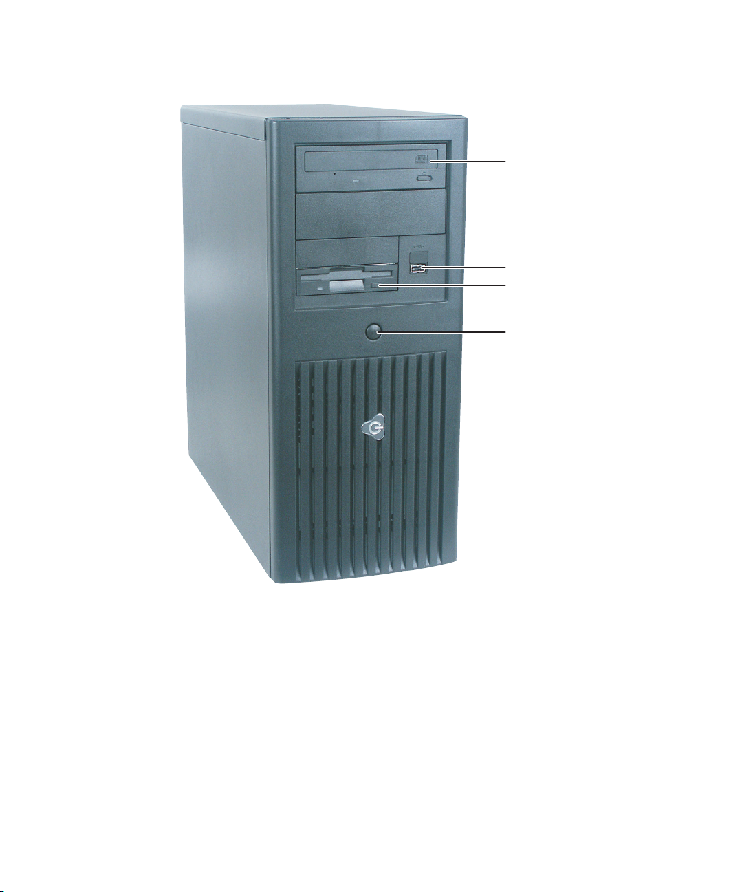
Front
CD drive
USB port
Diskette
drive
Power button
and power
LED indicator
www.gateway.com
3
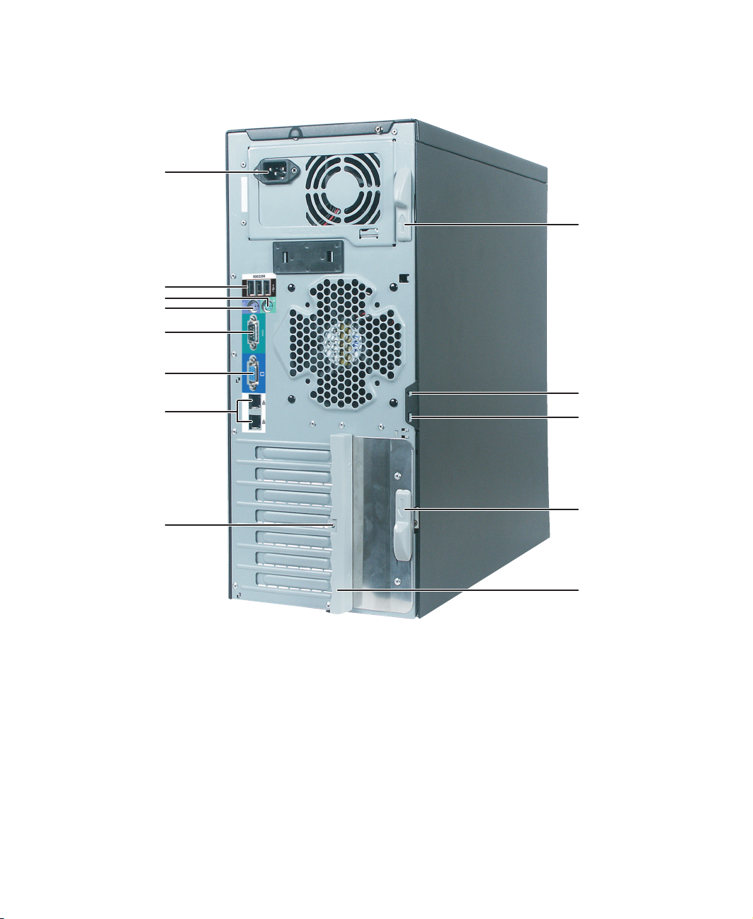
Back
Power connector
USB ports
Mouse port
Keyboard port
Serial port
Release latch
Monitor port
LAN jacks
Card retention
cover thumbscrew
Shipping
thumbscrew
Kensington
lock slot
Release latch
Card retention
cover
4
www.gateway.com
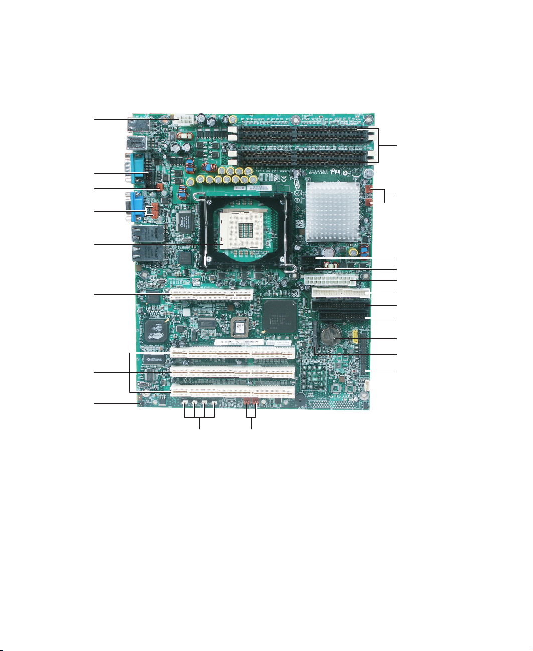
System board
Connectors
CPU power
connector
Serial port
connector
Processor
fan power
connector
System fan
power
connector
CPU slot
32-bit PCI
slot
64-bit PCI
slots
Memory slots
System fan power
connectors
Front panel USB
connector
Auxiliary power connector
Main power connector
Secondary IDE connector
Primary IDE connector
Diskette drive connector
Battery
SATA 1 and 2
connectors
Front panel
connector
Chassis
intrusion
switch
connector
System
jumpers
System fan
power
connectors
www.gateway.com
5

Getting Help
In addition to your operating system’s documentation, you can use the following
information resources to help you use your server.
System Companion CD
Use the System Companion CD to access file utilities, hardware drivers, and documentation
for your server and its components. For more information, see “Using your System
Companion CD” on page 20.
Gateway Web site
Gateway provides a variety of information on its Web site to help you use your server.
Visit the Gateway Web site at support.gateway.com for:
■ Technical documentation and product guides
■ Technical tips and support
■ Updated hardware drivers
■ Order status
■ Frequently asked questions (FAQs)
Telephone support
You can access a wide range of services through your telephone, including customer service,
technical support, and information services. For more information, see “Telephone
support” on page 64.
6
www.gateway.com

Chapter 2
Setting Up Your Server
■ Use your server safely
■ Start and turn off your server
■ Set up your operating system
7

Setting up the hardware
To make sure that your working environment is safe:
■ Use a clean, dry, flat, stable surface for your server. Allow at least 6 inches at the rear
of the server for cabling and air circulation.
■ Use a grounded (three-prong) surge protector. A surge protector helps protect against
AC power fluctuations. For additional protection from power outages, we recommend
that you use an uninterruptible power supply (UPS).
Warning Your server comes with a 3-wire AC power cord fitted with
the correct plug style for your region. If this plug does not
match the connector on your surge protector, UPS, or wall
outlet, do not attempt to modify the plug in any way.
Otherwise you may damage the server or create a fire
hazard. Use a surge protector, UPS, or wall outlet that is
appropriate for the supplied AC power cord.
■ Avoid subjecting your server to extreme temperature changes. Do not expose your
server to direct sunlight, heating ducts, or other heat-generating objects. Damage
caused by extreme temperatures is not covered by your warranty. As a general rule,
your server is safest at temperatures that are comfortable for you.
■ Keep your server and magnetic media away from equipment that generates magnetic
fields, such as unshielded stereo speakers. Strong magnetic fields can erase data on
both diskettes and hard drives. Even a telephone placed too close to the server may
cause interference.
Important Keep the server boxes and packing material in case you
need to ship the server.
8
www.gateway.com

Protecting from power source problems
Surge protectors, line conditioners, and uninterruptible power supplies can help protect
your server against power source problems.
Surge protectors
During a power surge, the voltage level of electricity coming into your server can increase
to far above normal levels and cause data loss or server damage. Protect your server and
peripheral devices by connecting them to a surge protector, which absorbs voltage surges
and prevents them from reaching your server.
Warning High voltages can enter your server through the power
cord, and the modem and network connections. Protect
your server by using a surge protector. If you have a
modem, use a surge protector that has the appropriate
type of modem jack. During an electrical storm, unplug the
surge protector and the modem and network cables.
When you purchase a surge protector:
■ Make sure that the surge protector meets the appropriate product safety certification
for your location, such as Underwriters Laboratories (UL).
■ Check the maximum amount of voltage the protector allows to pass through the line.
The lower the voltage that the protector allows to pass through, the better the
protection for your server.
■ Check the energy absorption (dissipation) rating. The higher the energy absorption
rating, the better the protection for your server.
■ Check for line-conditioner capabilities. A line conditioner smooths out some of the
normal line noise (small voltage fluctuations) of an electrical supply.
Line conditioners
A line conditioner protects your server from the small fluctuations in voltage from an
electrical supply. Most servers can handle this variation, called line noise, without problems.
However, some electrical sources include more line noise than normal. Line noise can also
be a problem if your server is located near, or shares a circuit with, a device that causes
electromagnetic interference, such as a television or a motor.
Some surge protectors and uninterruptible power supplies include simple line-conditioning
capabilities.
www.gateway.com
9

Uninterruptible power supplies
Use an uninterruptible power supply (UPS) to protect your server from data loss during a
total power failure. A UPS uses a battery to keep your server running temporarily during
a power failure and lets you save your work and shut down your server. You cannot run
your server for an extended period of time while using only the UPS. To buy a UPS, visit
accessories.gateway.com
.
10
www.gateway.com
Starting your server
Before you start your server for the first time:
■ Make sure that the server and monitor are plugged into a power outlet or surge
protector and that the surge protector (if you are using one) is turned on.
■ Make sure that all cables are connected securely to the correct ports and jacks on the
back of the server.
Warning When you connect peripheral devices to the server, make
sure that your server and devices are turned off and the
power cords are unplugged.
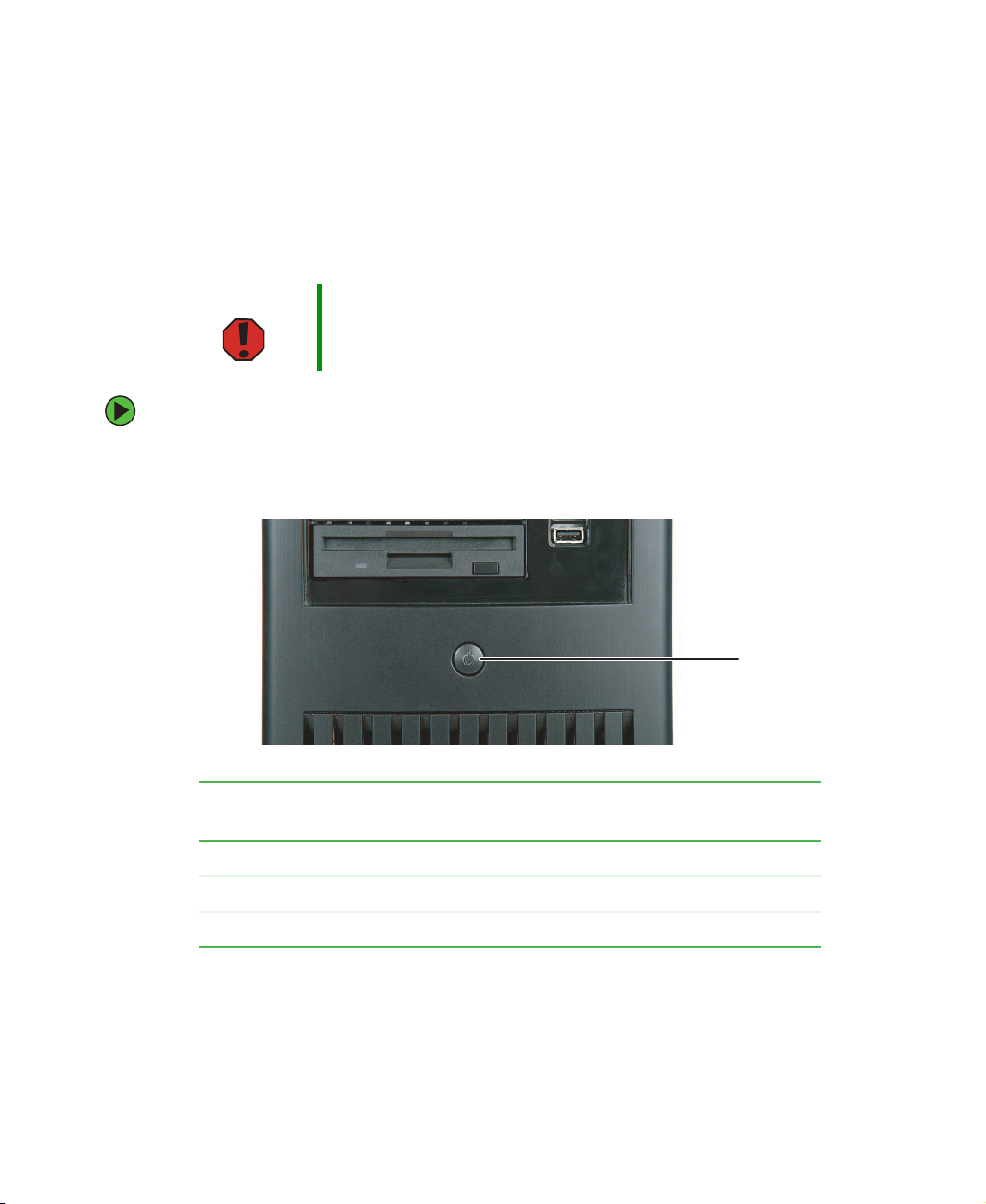
To start the server:
1 Turn on any peripheral devices connected to the server.
2 Press the power button.
When the power
indicator is...
Green (steady on) The server is turned on.
Orange The server is in Standby mode.
Off The server is turned off.
It means...
www.gateway.com
Power
button
11

If nothing happens when you press the power button:
■ Make sure that the power cable is plugged in securely and that your surge protector
(if you are using one) is plugged in and turned on.
■ Make sure that the monitor is connected to the server, plugged into the power
outlet or surge protector, and turned on. You may also need to adjust the monitor’s
brightness and contrast controls.
■ If you cannot find the cause of the power loss, contact Gateway Technical Support.
For more information, see “Getting Help” on page 6.
3 The first time you turn on the server, any pre-installed operating system may begin
asking you for configuration settings. See your operating system’s documentation for
instructions on configuring advanced settings for your specific network.
Understanding the power-on self-test
When you turn on your server, the power-on self-test (POST) routine checks the server
memory and components. If POST finds any problems, the server displays error messages.
Write down any error messages that you see, then see “Error messages” on page 67 and
“Beep codes” on page 70 for troubleshooting information.
12
www.gateway.com

Turning off your server
Every time you turn off your server, first shut down the operating system. You may lose
data if you do not follow the correct procedure.
To turn off the server:
1 See the operating system’s documentation or online help for instructions on shutting
down the operating system. Whenever possible, you should use the operating system’s
shut down procedure instead of pressing the power button.
Warning The power button on the server does not turn off server
AC power. To remove AC power from the server, you must
unplug the AC power cord from the wall outlet or power
source. The power cord is considered the disconnect
device to the main (AC) power.
2 If your server did not turn off automatically, press the power button.
- OR -
Press the reset button to reset the server.
Setting up the operating system
If you ordered your server with the operating system already installed by Gateway, it is
completely installed and the basic settings are already configured. See your operating
system’s documentation for instructions on configuring advanced settings for your specific
network.
If you are installing an operating system because it was not already installed by Gateway,
see the appropriate installation guide for instructions.
www.gateway.com
13

14
www.gateway.com

Chapter 3
Maintaining Your Server
■ Care for your server
■ Record the BIOS configuration
■ Manage your server and network
15

Caring for your server
To extend the life of your server:
■ Be careful not to bump or drop your server.
■ When transporting your server, we recommend that you put it in the original
packaging materials.
■ Keep your server and magnetic media away from equipment that generates magnetic
fields, such as unshielded speakers.
■ Avoid subjecting your server to extreme temperatures. Do not expose your server to
heating ducts or other heat-generating objects. Damage caused by extreme
temperatures is not covered by your warranty. As a general rule, your server is safest
at temperatures that are comfortable for you.
■ Keep all liquids away from your server. When spilled onto server components, almost
any liquid can result in extremely expensive repairs that are not covered under your
warranty.
■ Avoid dusty or dirty work environments. Dust and dirt can clog the internal
mechanisms and can cause the server to overheat.
Cleaning your server
Keeping your server clean and the vents free from dust helps keep your server performing
at its best. Your server cleaning kit could include:
■ A soft, lint-free cloth
■ Glass cleaner
■ An aerosol can of air with a narrow, straw-like extension
■ Isopropyl alcohol
■ Cotton swabs
■ A CD drive cleaning kit
Cleaning tips
■ Always turn off your server and other peripheral devices before cleaning any
components.
Warning When you shut down your server, the power turns off, but
some electrical current still flows through your server. To
avoid possible injury from electrical shock, unplug the
power cord and all other cables connected to the server.
16
www.gateway.com

■ Use a damp, lint-free cloth to clean your server and other parts of your server system.
Do not use abrasive or solvent cleaners because they can damage the finish on
components.
■ Keep the cooling vents free of dust. With your server turned off and unplugged, brush
the dust away from the vents with a damp cloth, but be careful not to drip any water
into the vents.
Cleaning the keyboard
You should clean the keyboard occasionally by using an aerosol can of air with a narrow,
straw-like extension to remove dust and lint trapped under the keys.
If you spill liquid on the keyboard, turn off your server and turn the keyboard upside down
to let the liquid drain. Let the keyboard dry completely before trying to use it again. If
the keyboard does not work after it dries, you may need to replace it. Keyboard damage
resulting from spilled liquids is not covered by your warranty.
Cleaning the screen
If your computer screen is a flat panel display, use only a damp, soft cloth to clean it.
Never spray water directly onto the screen.
Caution The computer screen is made of specially coated glass
and can be scratched or damaged by abrasive or
ammonia-based glass cleaners.
- OR -
If your computer screen is not a flat panel display, use a soft cloth dampened with glass
cleaner to clean the screen. Never spray cleaner directly onto the screen.
www.gateway.com
17

Preparing for system recovery
If your system files are corrupted, you may not be able to start the server from the hard
drive. Startup diskettes are diskettes that let you start the server and attempt to fix the
problem. See your operating system’s documentation or online help for instructions on
creating startup diskettes.
Some operating systems also let you create an emergency repair diskette to back up critical
operating system files. See your operating system’s documentation or online help for
instructions on creating and using an emergency repair diskette.
Recording the BIOS configuration
To help keep track of your custom changes to BIOS settings and to prepare for system
recovery, you should record your BIOS configuration after you have your server set up and
working.
To record your BIOS configuration:
1 Print the appendix for “BIOS Settings” on page 83.
2 Restart your server, then press F2 when the Gateway logo screen appears during
startup. The BIOS Setup utility opens.
3 Record the BIOS settings on your printout.
18
www.gateway.com

System administration
Gateway Systems Manager
Gateway Systems Manager 3.0 (GSM) lets you locally (using the Server console) and
remotely (using the Administrator console) monitor the health and performance of your
servers. From the Administrator console you can monitor any server that has one of the
two consoles installed. You can monitor critical indicators such as:
■ Hardware and software inventory and configuration changes
■ Computer health (temperature, voltage, free memory, and disk space)
■ Selected system events (specified by the administrator)
Printed documentation comes with the Gateway Systems Manager CD. You can find
additional documentation in the program’s online help.
Server security
Using BIOS security passwords
To prevent unauthorized use of the server, you can set server startup passwords. Set up
an administrator password to prevent unauthorized access to the BIOS Setup utility.
For information about resetting BIOS passwords, see “Changing jumper settings” on
page 60.
To set the BIOS security passwords:
1 Restart your server, then press F2 when the Gateway logo screen appears during
startup. The BIOS Setup utility opens.
2 Select the Security menu.
3 Select Administrator Password.
4 Type the password and press ENTER, then type it again and press ENTER.
5 Save your changes and close the BIOS Setup utility.
www.gateway.com
19

To remove a BIOS security password:
1 Restart your server, then press F2 when the Gateway logo screen appears during
startup. The BIOS Setup utility opens.
2 Select the Security menu, then select the password to remove.
3 Enter the current password, then press ENTER.
4 For the new password, leave the password field blank, then press ENTER. The password
is removed.
Tips & Tricks Passwords can also be cleared using jumpers on the
system board. For instructions, see “Changing jumper
settings” on page 60.
Using your System Companion CD
You can use your System Companion CD to:
■ Install hardware drivers
■ Install programs
■ View server documentation
Instructions for using the CD are provided in Using Your System Companion CD.
20
www.gateway.com

Using the System Setup Utility
The System Setup Utility (SSU) lets you:
■ View the System Event Log (SEL Mgr.)
■ View Sensor Data Records (SDR Mgr.)
■ View Field Replaceable Unit information (FRU Mgr.)
■ Set up the server to send alerts for platform events
■ Set up the remote LAN access for the server for out-of-band (OOB) access through
Gateway Server Manager
Important The SSU does not work within a DOS window running
under an operating system such as Windows.
Viewing System Event Log information
To view the System Event Log (SEL) information:
1 Boot your server from the System Companion CD, then select System Setup Utility from
the menu. The System Setup Utility starts.
2 From the System Setup Utility (SSU) main window, under Viewers, double-click SEL
Manager
. The system events log is displayed.
3 Double-click SEL, then click:
■ Properties to view the SEL properties
■ Clear SEL to clear the SEL contents.
■ Reload to refresh the SEL.
■ Sort by to select SEL sort options.
www.gateway.com
21

Viewing Sensor Data Records
To view the Sensor Data Records (SDR):
1 Boot your server from the System Companion CD, then select System Setup Utility from
the menu. The System Setup Utility starts.
2 In the SSU main window, under Viewers, double-click SDR Manager. SDR categories
are displayed in the left window pane.
3 In the left window pane, double-click a category. The category expands to show a list
of SDRs for that category.
4 Double-click an SDR. Information for that SDR is displayed.
Viewing Field Replaceable Unit information
To view the Field Replaceable Unit (FRU) information:
1 Boot your server from the System Companion CD, then select System Setup Utility from
the menu. The System Setup Utility starts.
2 From the SSU main window, under Viewers, double-click FRU Manager. The SSU
automatically loads the current list of events from non-volatile memory.
3 In the left window pane, double-click FRU Information to expand the categories.
4 Double-click the category for Product, Chassis, or Board. The category expands to show
a list of components for that category.
5 Double-click a component. Information for that component is displayed.
22
www.gateway.com

Setting up remote access
You can set up the server so you can perform system management tasks remotely.
Setting up remote LAN access
To set up remote LAN access:
1 Boot your server from the System Companion CD, then select System Setup Utility from
the menu. The System Setup Utility starts.
2 In the SSU main window, under Server Configuration, double-click LAN Setup.
3 To require a password for remote access, type the password in the Enter New Password
box and in the
long, using any ASCII character in the range 32-126.
To clear the password, leave both boxes blank. You can also clear the password by
clicking
Options, then Clear LAN Password.
4 Click the remote access mode from the LAN Access Mode list:
■ Always Available—A remote system can initiate a LAN connection regardless of the
state of the server.
■ Restricted—A remote system can initiate a LAN connection, but cannot perform
control operations such as turn off power, reset, or front panel NMI (non-maskable
interrupt).
Verify New Password box. Passwords can be from 1 to 16 characters
■ Disabled—Remote systems are not allowed to initiate LAN connections.
5 In the IP Setup box, click one:
■ DHCP—The IP address for the server is automatically assigned by the DHCP
(dynamic host control protocol) server on the network. The Host, Gateway, and
Subnet Mask boxes in the dialog box are ignored.
■ Static—Assign the IP address for the server using the Host, Gateway, and Subnet
Mask boxes in the dialog box.
6 If you selected Static in the previous step, complete the IP addressing boxes:
■ Gateway MAC Address—The physical address of the router for this server.
■ Host IP Address—The IP address of this server.
■ Gateway IP Address—The IP address of the router for this server.
■ Subnet Mask—The IP address for the server's subnet. The server uses this to decide
if the alert destination is on the same subnet.
www.gateway.com
23

7 Click Save to save the changes.
8 Click Close to return to the SSU main window.
Setting up LAN alerts
To set up LAN alerts:
1 Boot your server from the System Companion CD, then select System Setup Utility from
the menu. The System Setup Utility starts.
2 In the SSU main window, under Server Configuration, double-click LAN Setup.
3 Click to select the Enable LAN Alerts check box.
4 In the SNMP Community String box, you can type an optional string for the community
field in the
5 to 16 characters. The default string is public.
Header section of the SNMP trap sent for an alert. The string must be from
5 In the IP Setup box, click either:
■ DHCP—The IP address for the server is automatically assigned by the DHCP
(dynamic host control protocol) server on the network. The Host, Gateway, and
Subnet Mask boxes in the dialog box are ignored.
■ Static—Assign the IP address for the server using the Host, Gateway, and Subnet
Mask boxes in the dialog box.
6 If you chose Static IP Setup in the previous step, complete the IP addressing boxes:
■ Gateway MAC Address—The physical address of the router for this server.
■ Host IP Address—The IP address of this server.
■ Gateway IP Address—The IP address of the router for this server.
■ Subnet Mask—The IP address for the server’s subnet. The server uses this to decide
if the alert destination is on the same subnet.
7 In the Alert IP Address box, complete the IP address of the system you want to receive
alerts from this server. If you want the alert to be broadcast to an entire subnet, enter
the IP address for the subnet.
8 In the Alert IP MAC Address box, complete the physical Internet address (MAC address)
of the system you want to receive alerts from this server. Enter only valid hex values
for the Alert IP MAC address.
9 Click Options, then click Configure Event Actions.
24
www.gateway.com

10 In the mBMC LAN-Alerting Actions window, click the check box to select the options
that you want alerts turned on for:
■ Fan Failure
■ Temperature Sensor
11 Click Save to save the changes.
12 Click Close to return to the mBMC LAN Configuration window.
13 Click Save to save the changes.
14 Click Close to return to the SSU main window.
www.gateway.com
25

26
www.gateway.com

Chapter 4
Installing Components
■ Open and close the server case
■ Install or replace components
27

Preparing to install components
You must open your server case to install components. If you are not comfortable with
these procedures, get help from a computer service technician or contact Gateway
Technical Support.
Selecting a place to work
Work on your server in an area that:
■ Is clean (avoid dusty areas)
■ Is a low-static environment (avoid carpeted areas)
■ Has a stable surface on which to set your server
■ Has enough room to place all of your server parts
■ Is near a grounded outlet so you can test your server after installation
■ Is near a telephone (in case you need help from Gateway Technical Support). The
telephone must be directly connected to a telephone jack and cannot be connected
to your server.
Gathering the tools you need
Some tools and supplies that you may need to work on your server are:
■ A notebook to take notes
■ A Phillips screwdriver
■ A small flat-blade screwdriver
■ Small containers to store various types of screws
■ A grounding wrist strap (available at most electronic stores)
Getting Help
If you have questions about performing any of these procedures, contact Gateway
Technical Support. For more information, see “Getting Help” on page 6.
28
www.gateway.com

Preventing static electricity discharge
The components inside your server are extremely sensitive to static electricity, also known
as electrostatic discharge (ESD).
Warning To avoid exposure to dangerous electrical voltages and
moving parts, turn off your server and unplug the power
cord and modem cable before opening the server case.
Caution ESD can permanently damage electrostatic
discharge-sensitive components in the server. Prevent
ESD damage by following ESD guidelines every time you
open the server case.
Before working with server components, follow these guidelines:
■ Turn off the server, then unplug the power cords and all other cables.
■ Press the power button to drain any residual power from the server.
■ Wear a grounding wrist strap (available at most electronics stores) and attach it to a
bare metal part of the server. You can also touch a bare metal surface on the back of
the server with your finger.
Warning To prevent risk of electric shock, do not insert any object
into the vent holes of the power supply.
■ Avoid static-causing surfaces such as carpeted floors, plastic, and packing foam.
■ Avoid working on the server when your work area is extremely humid.
■ Remove components from their antistatic bags only when you are ready to use them.
Do not lay components on the outside of antistatic bags because only the inside of
the bags provide electrostatic protection.
■ Always hold expansion cards by their edges or their metal mounting brackets. Avoid
touching the edge connectors and components on the cards. Never slide expansion
cards or components over any surface.
www.gateway.com
29

Opening the server case
Because the components inside your server are extremely sensitive to static electricity, make
sure that you follow the instructions at the beginning of this chapter to avoid static
electricity damage.
Caution For correct cooling and air flow, always close the side panel
before you turn on the server. Operating the server without
the panel in place will cause the server to overheat.
To open the server:
1 Follow the instructions in “Preventing static electricity discharge” on page 29. Make
sure that you turn off the server, then unplug the power cord and all other cables
connected to the server.
2 Place the server on a stable, non-skid surface.
3 For more stability, place the server on its side.
4 If your case has a shipping thumbscrew installed on the back, remove the screw, then
push the cover release latches away from each other.
Shipping thumbscrew
30
www.gateway.com

5 Swing the side panel away from the case.
Closing the server case
To close the server case:
1 For more stability, set the server on its side.
2 Make sure that all of the internal cables are arranged inside the case so they will not
be pinched when you close the case.
3 Align the side panel’s front tabs into the case notches, then swing the side panel
toward the case until the release latches snap into place.
4 Set the case upright.
5 Reconnect the power cord and all other cables.
www.gateway.com
31

Installing drives
Your server’s standard configuration includes one CD drive, a 3.25 inch diskette drive, and
one SATA hard drive. Your server also has one additional 5.25-inch external drive bay, one
additional 3.5-inch external drive bay, and two additional internal drive bays.
CD drive
5.25-inch drive bay
3.5-inch drive bay
3.5-inch diskette drive
As you prepare to install drives, remember:
■ Before you install a drive, see the drive’s documentation for information on
configuring the drive, setting drive jumpers, and attaching cables.
■ You may need to configure the drives you install using the BIOS Setup utility. Press
F2 at startup to open the BIOS Setup utility.
■ Parallel ATA (PATA) hard drives, also known as IDE hard drives, can be configured as
single, master, slave, or cable-select. IDE CD drives can be configured as master, slave,
or cable-select.
■ If cable-select is available (drive assignments will be marked on the cable), the PATA
cable assigns the master/slave positions to the drives it connects. You can override
these assignments using the jumpers on the drives.
■ If cable-select is not available and only one drive is attached to a PATA controller
cable, configure the drive as master if it is a CD drive. If two drives of any type
are attached to the cable, configure one as master and one as slave.
32
www.gateway.com

■ If you are connecting two PATA drives to the cable, connect the middle cable
connector to the slave drive and connect the end cable connector to the master
(boot) drive.
■ You may need to configure the drives you install using the BIOS Setup utility. Press
F2 at startup to open the BIOS Setup utility.
Installing a CD or diskette drive
To install a CD or diskette drive:
1 Follow the instructions in “Preventing static electricity discharge” on page 29.
2 Follow the instructions in “Opening the server case” on page 30.
www.gateway.com
33

3 If you are replacing a drive, go to Step 6.
- OR -
If you are adding a new drive, press in on the two front cover release tabs, then swing
the front cover away from the server and remove the cover.
4 Press the drive bay face plate release tab, then swing the faceplate away from the front
cover and remove the face plate.
34
www.gateway.com
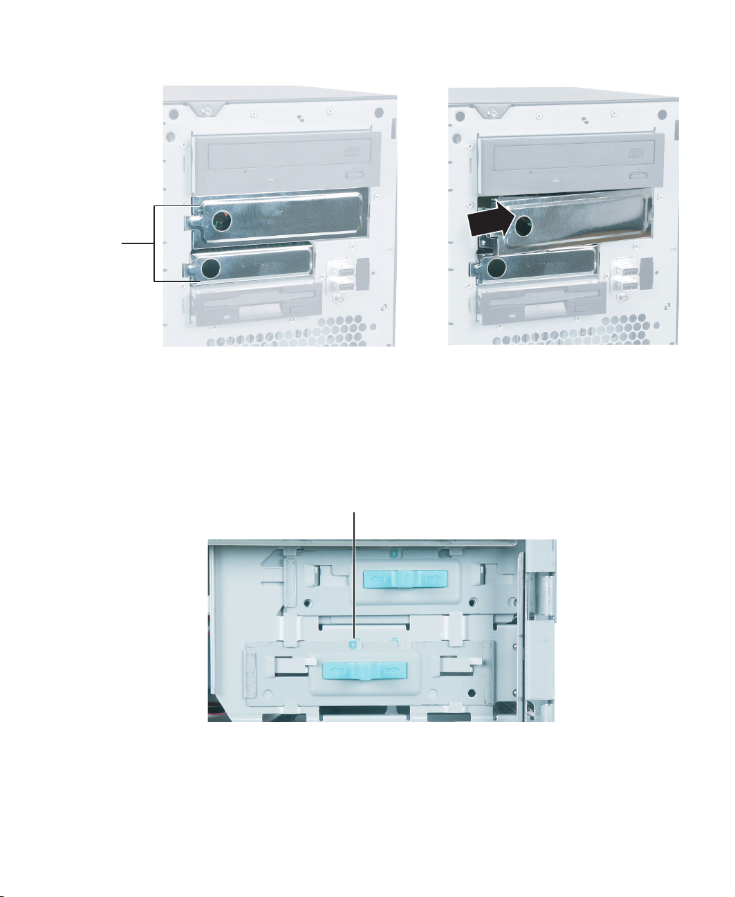
5 Remove the shield for the bay into which you are installing the new drive.
Shields
6 If you are replacing a drive, disconnect the drive cables.
7 If there is a shipping thumbscrew installed next to the drive release latch, remove
the thumbscrew.
8 Slide the drive release latch back toward the rear of the case until the unlock icon is
visible.
Unlock icon
9 If you are replacing a drive, slide it forward and out of the drive bay.
10 Set any jumpers on the new drive. See the drive’s documentation for further
instructions.
www.gateway.com
35

11 Slide the new drive into the drive bay.
12 Move the release latch to the right about ¼ inch (6 mm).
13 Align the drive’s screw holes with the release latch’s locking tabs.
Locking tabs
36
Drive screw
holes
www.gateway.com

14 Slide the drive release latch toward the front of the case until the lock icon is visible.
Lock icon
15 Follow the instructions in the drive’s documentation to connect the drive cables.
16 If you removed the front cover, replace it.
17 Follow the instructions in “Closing the server case” on page 31.
Installing a hard drive
Use this procedure to add or replace hard drives. The standard server configuration supports
as many as three, 1-inch high 3.5-inch hard drives.
A four channel SATA add-in card can be added to the server to support as many as three
SATA hard drives or a U320 SCSI add-in card can be added to support as many as three
SCSI hard drives. You can purchase additional SATA and SCSI hard drives and add-in cards
through your Gateway sales or Technical Support representative.
Important Gateway tests and verifies the operation and compatibility
of the drives it sells. Additional or replacement drives must
conform to Gateway standards, especially in a hot-swap
or mission-critical environment.
Important Drives connected to the primary and secondary IDE
connectors should be ATA100 drives.
www.gateway.com
37

To install a hard drive:
1 Follow the instructions in “Preventing static electricity discharge” on page 29.
Caution Before you remove a failed drive, use the appropriate
software and utilities installed on the server to stop all
activity on the failed drive. Instructions for using the
software are provided by the software manufacturer.
Failure to do so may destroy the data on the drive.
2 Follow the instructions in “Opening the server case” on page 30.
3 If you are replacing a hard drive, disconnect the data cable and power cable from the
drive to be replaced.
4 Slide the drive release latch toward the open side of the case.
38
www.gateway.com

5 If you are replacing a hard drive, slide the old drive out of the drive bay.
6 Set any jumpers on the new drive. See the drive’s documentation for further
instructions.
7 Slide the new drive in, then slide the release latch toward the inside of the case.
www.gateway.com
39

8 Follow the instructions in the drive’s documentation to connect the drive cables.
9 Follow the instructions in “Closing the server case” on page 31.
40
www.gateway.com

Installing memory
For best performance, we recommend that modules be installed in identical pairs. Use
184-pin single-sided or double-sided DDR Dual Inline Memory Modules (DIMM)
(DDR266/333/400). DIMMs may also be labeled as PC2100/PC2700/PC3200. First install
module pairs into Bank 1A and 2A, then install in Bank 1B and 2B. The server supports
as much as 4 GB unbuffered ECC total memory.
Caution For best performance, we recommend that modules be
installed in identical pairs. Use only DDR-266, 333, or 400
compliant, SDRAM unbuffered ECC, DIMM memory
modules.
Install memory first into Bank 1A and 2A, then install into
Bank 1B and 2B.
Bank 1A
and 2A
Bank 1B
and 2B
www.gateway.com
41

To install or replace memory:
1 Follow the instructions in “Preventing static electricity discharge” on page 29.
2 Follow the instructions in “Opening the server case” on page 30.
3 Pull the plastic tabs away from the sides of the memory module slot. If you are
replacing a memory module, lift the old module out of the slot.
4 Align the notch on the new module with the notch in the memory module slot and
press the module firmly into the slot. The tabs on the sides of the memory slot should
secure the memory module automatically.
5 Follow the instructions in “Closing the server case” on page 31.
6 Turn on the server, then make sure that the operating system completely loads. If you
receive an error, see “Memory” on page 74.
42
www.gateway.com

Installing a PCI expansion card
A PCI expansion card (sometimes called an add-in card) is a card used in the server to add
functionality to the system. Use the following procedure to replace, add, or reseat an
expansion card.
To replace, add, or reseat a PCI expansion card:
1 Follow the instructions in “Preventing static electricity discharge” on page 29.
2 Follow the instructions in “Opening the server case” on page 30.
3 If you are replacing a card, disconnect any cables that are attached to the old card.
4 Remove the thumbscrew that secures the expansion card retention cover to the server
case.
Thumbscrew
Caution Do not touch the contacts on the bottom part of the PCI
card. Touching the contacts can cause electrostatic
damage to the card.
www.gateway.com
43

5 While holding the retention cover open, remove the expansion card. You can slightly
seesaw the card end-to-end to loosen the card, but do not bend the card sideways.
Caution Do not touch the contacts on the bottom part of the PCI
expansion card. Touching the contacts can cause
electrostatic damage to the card.
6 While holding the retention cover open, press the new card into the expansion slot.
You can slightly seesaw the card end-to-end to help insert the card, but do not bend
the card sideways.
7 Connect any cables to the PCI expansion card following the instructions in the card’s
documentation.
8 Follow the instructions in “Closing the server case” on page 31.
9 See the PCI expansion card’s documentation for software installation instructions.
44
www.gateway.com

Replacing a processor
This server is compatible with Intel® Pentium 4® or Celeron® processors. The server
automatically detects the processors each time you turn on the server. Whenever you install
a new processor, you should first install the most current version of the BIOS. For
instructions, see “Updating the BIOS” on page 59.
Warning Processors and heat sinks may be hot if the computer has
been running. Before replacing a processor or heat sink,
allow them to cool for several minutes.
Caution A heat sink must be installed on the processor. Installing
a processor without a heat sink could damage the
processor.
To replace a processor:
1 Install the most current BIOS version. For instructions, see “Updating the BIOS” on
page 59.
2 Follow the instructions in “Preventing static electricity discharge” on page 29.
3 Follow the instructions in “Opening the server case” on page 30.
4 Unplug the heat sink’s cooling fan from the system board.
5 Press down on the heat sink locking lever on each side, push them slightly away from
the heat sink, then lift the levers out of the way.
www.gateway.com
45

6 Remove the heat sink.
Important The heat sink phase change material may harden over
time and hold the heat sink securely to the processor.
Make sure that you gently twist and lift to release the heat
sink from the processor. If the heat sink pulls the processor
out of the processor socket, the processor should still be
undamaged. Continue with Step 7 of this procedure.
7 Press down on the processor locking lever, push it slightly away from the processor,
then rotate the lever straight up to release the processor.
8 Remove the old processor.
9 Install the new processor into the processor slot. Make sure that the arrow on the
corner of the processor aligns with Pin 1 on the processor socket (the socket corner
without a pin hole).
10 Press the processor locking lever down until it clicks into place.
11 Apply thermal grease to the top of the processor, if necessary.
12 Place the heat sink on the processor, then press the heat sink locking levers down
until they click into place.
13 Plug the heat sink’s cooling fan into the system board.
14 Follow the instructions in “Closing the server case” on page 31.
46
www.gateway.com
Replacing the power supply
Warning The power supply in this server contains no
user-serviceable parts. Only a qualified computer
technician should service the power supply.
Your server comes with a 3-wire AC power cord fitted with
the correct plug style for your region. If this plug does not
match the connector on your surge protector, UPS, or wall
outlet, do not attempt to modify the plug in any way. Use
a surge protector, UPS, or wall outlet that is appropriate
for the supplied AC power cord.
To replace the power supply:
1 Follow the instructions in “Preventing static electricity discharge” on page 29.
2 Follow the instructions in “Opening the server case” on page 30.
3 Disconnect the power supply cables from all components, noting their locations and
orientation. (You will reconnect the cables after you install the new power supply.)
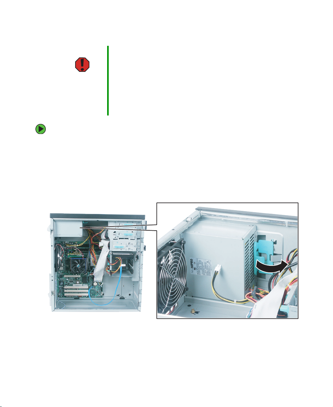
4 Pull the power supply retention clip away from the power supply.
www.gateway.com
47

5 While supporting the power supply with your hand, slide the power supply toward
the front of the case, then out toward the bottom of the case.
6 Install the new power supply, then press the retention clip back against the case.
7 Reconnect the power supply cables.
8 Follow the instructions in “Closing the server case” on page 31.
48
www.gateway.com

Replacing the CMOS battery
If the server clock does not keep time or the settings in the BIOS Setup utility are not saved
when you turn off the server, replace the CMOS battery with an equivalent battery.
Warning Danger of explosion if battery is incorrectly replaced.
Replace only with the same or equivalent type
recommended by the manufacturer. Dispose of or recycle
used batteries by taking them to a hazardous waste facility.
Follow all local regulations for correct battery disposal.
To replace the battery:
1 Print the appendix for “BIOS Settings” on page 83.
2 Open the BIOS Setup utility. For instructions, see “Opening the BIOS Setup utility”
on page 58.
3 Record the BIOS settings on your printout, then close the utility.
4 Turn off your server, then follow the instructions in “Preventing static electricity
discharge” on page 29.
5 Follow the instructions in “Opening the server case” on page 30.
6 Locate the old battery on the system board and note its orientation. You will need
to install the new battery the same way.
CMOS
battery
7 Push the battery retention clip away from the battery until the battery pops up, then
remove the old battery. You can use a screwdriver to help lift the battery.
8 Make sure that the positive (+) side of the new battery is facing up, then press the
new battery into the socket until it snaps into place.
www.gateway.com
49

9 Follow the instructions in “Closing the server case” on page 31.
10 Turn on your server, then press F2 when the Gateway logo screen appears during
startup.
11 Restore any BIOS settings that you wrote down in Step 3.
12 Save all your settings and close the BIOS Setup utility.
50
www.gateway.com

Replacing the system board
To replace the system board:
1 Print the appendix for “BIOS Settings” on page 83.
2 Restart your server, then press F2 when the Gateway logo screen appears during
startup.
3 Record any custom BIOS settings on your printout, then close the BIOS utility.
4 Follow the instructions in “Preventing static electricity discharge” on page 29.
5 Follow the instructions in “Opening the server case” on page 30.
6 Remove the memory modules. For instructions, see “Installing memory” on page 41.
7 Remove the PCI expansion cards. For instructions, see “Installing a PCI expansion
card” on page 43.
8 Remove the heat sink and processor. For instructions, see “Replacing a processor” on
page 45.
9 Disconnect the power and data cables from the system board, noting their locations
and orientation. (You will reconnect the cables after you install the new board.) Make
sure that you disconnect the intrusion switch cable.
Intrusion switch connector
www.gateway.com
Thumbscrew
51

10 Remove the system board thumbscrew.
11 Slide the system board toward the front of the case, then lift it away from the case.
Important The new system board must have special standoffs
(
pem studs
necessary, use the standoffs from the original system
board.
) mounted on the bottom of the board. If
12 Slide the new system board’s standoffs into the keyhole slots, then slide the board
toward the back of the case.
Standoff
Keyhole slot
52
www.gateway.com

13 Lock the system board into place with the thumbscrew.
14 Install the memory, processor, and heat sink, then reconnect the heat sink cooling
fan to the system board.
15 Connect the power and data cables.
16 Install the expansion cards. For more information, see “Installing a PCI expansion
card” on page 43.
17 Follow the instructions in “Closing the server case” on page 31.
18 Turn on your server.
19 Press F2 when the Gateway logo screen appears during startup. The BIOS Setup utility
opens.
20 Check BIOS settings to make sure that they detect the server’s new hardware, then
save your changes (if any) and close the BIOS Setup utility.
21 If your server does not start after installing the new system board, contact Technical
Support. For more information, see “Getting Help” on page 6.
www.gateway.com
53

Replacing the fan
To replace the fan:
1 Follow the instructions in “Preventing static electricity discharge” on page 29.
2 Follow the instructions in “Opening the server case” on page 30.
3 Unplug the case fan from the system board.
Rear fan connector
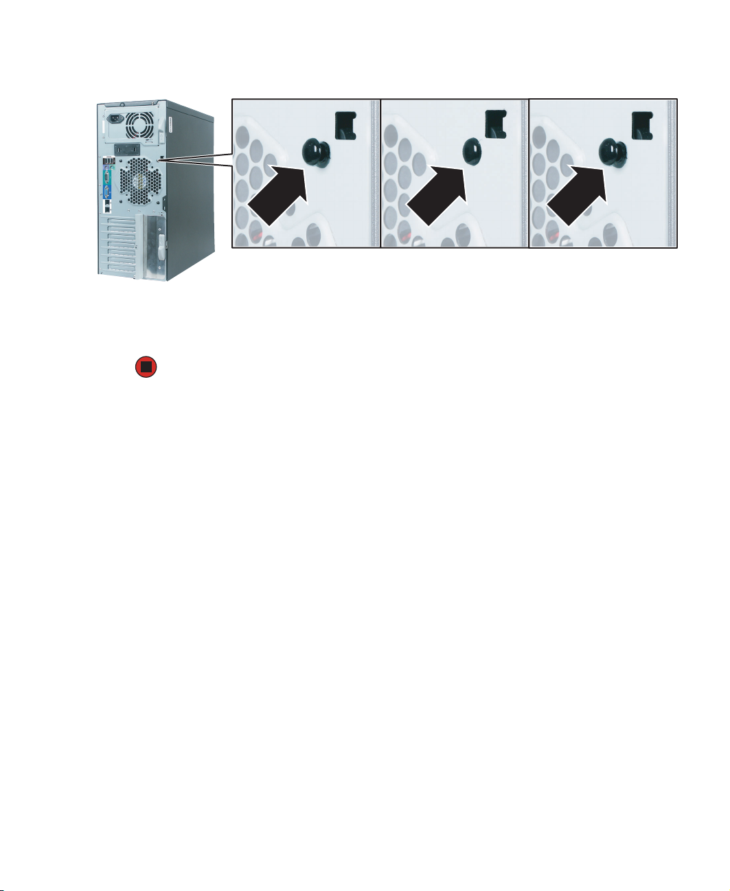
4 Use a narrow tool, such as a small screwdriver, to push each of the four fan mounting
rivets and sleeves out toward the back of the case.
5 Remove each rivet, then remove the old fan.
54
www.gateway.com
6 Hold the new fan in place while you push the fan’s rivet sleeves into the fan from
the outside of the case, then push the rivets into the sleeves.
7 Reconnect the case fan to the system board.
8 Follow the instructions in “Closing the server case” on page 31.
www.gateway.com
55

56
www.gateway.com

Chapter 5
Using the BIOS Setup Utility
■ Open the BIOS Setup utility
■ Update the BIOS
■ Reset the BIOS settings to the factory
defaults
■ Reset the BIOS passwords
57

Opening the BIOS Setup utility
The BIOS Setup utility stores basic settings for your server. These settings include basic
hardware configuration, resource settings, and password security. These settings are stored
and saved even when the power is off.
Caution The options in the BIOS Setup utility have been set at the
factory for optimal performance. Changes to these
settings will affect the performance of your server.
Before changing any settings, write them down in case
you need to restore them later. You can record the settings
on a printout of this guide’s appendix for “BIOS Settings”
on page 83.
To open the BIOS Setup utility:
1 Restart your server, then press F2 when the Gateway logo screen appears during
startup.
When you select menu items, the Item Specific Help box on the right side of the screen
displays specific information about the selection. The command bar across the bottom
of the screen shows the keys you press to access help, navigate through the menus,
and perform other tasks.
2 Select one of these menus:
■ Main gives you access to basic information and settings related to your server’s
hardware and configuration.
■ Advanced gives you access to information and settings for PCI, peripheral devices,
memory, and the chipset.
■ Boot gives you access to information and settings for startup features and startup
sequences.
■ Security gives you access to settings related to system access passwords. For more
information, see “Server security” on page 19.
■ Server gives you access to settings for system management, console redirection,
event log configuration, and fault-resilient boot settings.
■ Exit gives you access to options for closing the BIOS Setup utility.
58
www.gateway.com

Updating the BIOS
If you need a new version of the BIOS, you can download the BIOS update from the
Gateway Web site, then install the new version from a diskette.
To update the BIOS:
1 Print the appendix for “BIOS Settings” on page 83.
2 Restart your server, then press F2 when the Gateway logo screen appears during
startup.
3 Record any custom BIOS settings on your printout, then close the BIOS utility.
4 Download the BIOS update from support.gateway.com.
5 Follow the instructions in the self-extracting BIOS update file.
6 Restart your server, then press F2 when the Gateway logo screen appears during
startup.
7 Enter any custom BIOS settings you recorded in Step 3, then save your changes and
close the BIOS Setup utility.
www.gateway.com
59

Changing jumper settings
You can change the J1D1 jumper settings on the system board to:
■ Recover the BIOS configuration
■ Disable the BIOS Flash write-protect
■ Clear the current system password
■ Clear the CMOS
To change jumper settings
1 Print the appendix for “BIOS Settings” on page 83.
2 Restart your server, then press F2 when the Gateway logo screen appears during
startup.
3 Record any custom BIOS settings on your printout.
4 Follow the instructions in “Preventing static electricity discharge” on page 29.
5 Turn off the server, then disconnect the power cord and all other cables connected
to the server.
6 Open the case. For instructions, see “Opening the server case” on page 30.
Caution Moving the jumper while the power is on can damage your
server. Always turn off the server and unplug the power
cord and all other cables before changing the jumper.
7 Place a jumper across the indicated pins of jumper J1D1, as required, for the BIOS
function you want to perform (see the following table).
DCBA
60
www.gateway.com

Item Function/Mode Jumper Setting Configuration
A Normal boot
Recovery boot
B BIOS bootblock
protect
BIOS bootblock
unprotect
C Password protect
Password clear
D CMOS normal
CMOS clear
Pins 1 and 2
Pins 2 and 3
Pins 4 and 5
Pins 5 and 6
Pins 7 and 8
Pins 8 and 9
Pins 10 and 11
Pins 11 and 12
The BIOS uses current configuration information
and passwords for booting.
The BIOS attempts to recover the BIOS
configuration. A formatted BIOS recovery diskette
is required.
The BIOS bootblock is in protected mode.
The BIOS bootblock is in unprotected mode and
can be updated (flashed) with a current BIOS. For
more information, see “Updating the BIOS” on
page 59.
The system password setting is in protected
mode.
The system password setting is in unprotected
mode.
The CMOS is in normal operation.
The CMOS content is cleared.
8 Follow the instructions in “Closing the server case” on page 31.
9 Turn on your server. Your server completes the action specified by the jumper setting
you made.
10 Turn off the server, then disconnect the power cord.
11 Open the case again. For instructions, see “Opening the server case” on page 30.
12 Return the jumper in its initial setting on J1D1 to change the setting you made in
Step 7 back to the normal setting.
13 Follow the instructions in “Closing the server case” on page 31.
www.gateway.com
61

62
www.gateway.com

Chapter 6
Troubleshooting
■ Get telephone support and training
■ Interpret error messages and codes
■ Troubleshoot
If the suggestions in this chapter do not correct
the problem, see “Telephone support” on
page 64 for more information about how to get
help.
63

Telephone support
Before calling Gateway Technical Support
If you have a technical problem with your server, follow these recommendations before
contacting Gateway Technical Support:
■ Make sure that your server is connected correctly to a grounded AC outlet that is
supplying power.
■ If a peripheral device, such as a keyboard or mouse, does not appear to work, make
sure that all cables are plugged in securely and plugged into the correct port or jack.
■ If you have recently installed hardware or software, make sure that you have installed
it following the instructions provided with it. If you did not purchase the hardware
or software from Gateway, see the manufacturer’s documentation and technical
support resources.
■ If you have “how to” questions about using a program, see:
■ The program’s online Help
■ The program’s documentation
■ Your operating system’s documentation
■ The software or hardware manufacturer’s Web site
■ See “Troubleshooting” on page 69.
■ Have your client ID, serial number (located on the back of your server case), and order
number available, along with a detailed description of your issue, including the exact
text of any error messages, and the steps you have taken.
■ Make sure that your server is nearby at the time of your call. The technician may have
you follow appropriate troubleshooting steps.
■ Consider using Gateway’s Internet technical support. Gateway’s Web site has FAQs,
tips, and other technical help. You can also use the Web site to e-mail Technical
Support. For more information, visit Gateway’s Technical Support Web site at
support.gateway.com
64
.
www.gateway.com

Technical support
Gateway offers a wide range of customer service, technical support, and information
services.
Telephone numbers
You can access the following services through your telephone to get answers to your
questions:
Resource Service description How to reach
Gateway
Technical Support
Sales,
accounting, and
warranty
Talk to a Gateway Technical Support
representative.
(TDD is also available at this number)
Get information about available systems,
pricing, orders, billing statements, warranty
service, or other non-technical issues.
877-485-1464 (US)
800-846-2000 (US)
888-888-2037 (Canada)
www.gateway.com
65

Safety guidelines
While troubleshooting your server, follow these safety guidelines:
■ Never remove the side panel while your server is turned on and while the modem
cable and the power cord is connected.
■ Do not attempt to open the monitor. To do so is extremely dangerous. Even if the
power is disconnected, energy stored in the monitor components can be dangerous.
Also, opening the monitor voids its warranty.
■ Make sure that you are grounded correctly before opening the server. For more
information about preventing damage from static electricity, see “Preventing static
electricity discharge” on page 29.
■ After you complete any maintenance task where you have to open the server case,
make sure that you close the case and reconnect all cables before you restart your
server.
Warning To avoid bodily injury, do not attempt to troubleshoot your
server problem if:
■
The power cord or plug is damaged
■
Liquid has been spilled into your server
■
Your server was dropped
■
The case was damaged
Instead, unplug your server and contact a qualified
computer technician. If your server was damaged during
shipment from Gateway, contact Gateway Technical
Support. For more information, see “Telephone support”
on page 64.
66
www.gateway.com

Error messages
These messages often indicate procedural errors such as typing an incorrect keystroke or
trying to save a file to a write-protected diskette. Some messages, however, may indicate
a problem that requires further troubleshooting.
Diskette drive 0 seek to track 0 failed
■ Restart your server, then open the BIOS Setup utility by pressing and holding F2 while
your server restarts. Make sure that the drive settings are correct.
Error loading operating system
■ The master boot record may be corrupt. For troubleshooting information, see “The
master boot record is corrupted” on page 74.
Hard disk controller failure
■ Make sure that the hard drive cable is connected securely.
■ Restart your server, then open the BIOS Setup utility by pressing and holding F2 while
your server restarts. Make sure that the correct drive type is selected.
Hard disk controller failure - press F1 to try reboot
■ The drive controller may be defective. Press F1 to try to restart the server. For more
information about running diagnostics on your hard drive, see your operating system’s
documentation.
Insert bootable media device
■ Restart your server, then open the BIOS Setup utility by pressing and holding F2 while
your server restarts. Make sure that the drive settings are correct.
■ See “Your server does not recognize an SCSI drive (applies to SCSI configured servers
only)” on page 73 for a possible solution.
Invalid configuration information
■ Restart your server, then open the BIOS Setup utility by pressing and holding F2 while
your server restarts. Make sure that the settings are correct.
■ Reset the BIOS. For instructions, see “Changing jumper settings” on page 60.
Invalid partition table
■ The master boot record may be corrupt. For troubleshooting information, see “The
master boot record is corrupted” on page 74.
www.gateway.com
67

Invalid password
■ Enter your password again. Some passwords are case sensitive.
■ If you do not know the password, you may need to reinstall the software you are trying
to access.
■ System startup passwords are stored in BIOS. If this password has been set and you
do not know it, you may be able to reset the password through system board jumper
settings. For instructions, see “Changing jumper settings” on page 60.
Memory errors were detected while the system started up
■ See “Memory errors were detected during server start up” on page 74 for a possible
solution.
Memory size error
■ Restart your server, then open the BIOS Setup utility by pressing and holding F2 while
your server restarts. Save the memory configuration.
Missing operating system
■ The master boot record may be corrupt. For troubleshooting information, see “The
master boot record is corrupted” on page 74.
System Event Log Full
■ Clear the event log. To clear or view the event log, restart your server, then open the
BIOS Setup utility by pressing and holding F2 while your server restarts. Select the
Server menu, then select the Event Log Configuration menu.
68
- OR -
Clear the System Event Log using the System Setup Utility, for more information, see
“Viewing System Event Log information” on page 21.
www.gateway.com

Troubleshooting
First steps
Try these steps first before going to the following sections:
■ Make sure that the power cord is connected to your server and an AC outlet and that
the AC outlet is supplying power.
■ If you use a surge protector or a UPS, make sure that it is turned on and is rated to
handle the power required by your server.
■ If you added or removed server components before the problem started, review the
installation procedures you performed and make sure that you followed each
instruction. You may need to remove the device, uninstall the device’s software, then
reinstall the device.
■ If an error message appears on the screen, write down the exact message before calling
Gateway Technical Support. For more information, see “Telephone support” on
page 64.
■ Restart your server, then open the BIOS Setup utility by pressing and holding F2 while
your server restarts. Check your configuration settings.
■ If an error occurs in a program, see its documentation or online help.
Warning To avoid bodily injury, do not attempt to troubleshoot your
server problem if:
■
The power cord or plug is damaged
■
Liquid has been spilled into your server
■
Your server was dropped
■
The case was damaged
Instead, unplug your server and contact a qualified
computer technician.
www.gateway.com
69

Battery replacement
If you have problems after installing a new CMOS battery, try each of the following items,
closing the case and restarting the server after each try:
■ Restart your server, then open the BIOS Setup utility by pressing and holding F2 while
your server restarts. Correct any discrepancies.
■ Remove the side panel by following the instructions in “Opening the server case” on
page 30, then make sure that all cables inside the case are attached securely. Also, make
sure that the colored cable edges are aligned correctly and that the connectors do not
miss any pins.
Warning To avoid bodily injury, do not attempt to troubleshoot your
server problem if:
■
The power cord or plug is damaged
■
Liquid has been spilled into your server
■
Your server was dropped
■
The case was damaged
Instead, unplug your server and contact Gateway
Technical Suppor t or a qualified computer technician.
■ If you have the correct test equipment, make sure that the new battery has power.
Although unlikely, your new battery may be defective.
Beep codes
Whenever a recoverable error occurs during the power-on self-test (POST), the BIOS
displays an error message that describes the problem. The BIOS also sounds a beep code
for errors when video is not available for text messages.
A PCI expansion card (for example, a RAID controller) can also issue audible errors by itself,
usually consisting of one long tone followed by a series of short tones. For more
information on the beep codes issued, check the documentation for that device.
70
www.gateway.com

Beeps Description Troubleshooting steps
1 The memory refresh circuitry on the
system board is faulty.
Reseat the memory or replace with
modules you know are good.
2 Parity cannot be reset. Same as 1 beep.
3 Base memory test failure. Same as 1 beep.
4 System timer is not operational. Remove all expansion cards.
■
If the beep code occurs even when all
expansion cards have been removed,
the system board may be at fault.
Contact Gateway Technical Support.
■
If the beep code does not occur when
the expansion cards have been
removed, one of the cards is causing
the problem. Install the cards one at a
time until the problem happens again.
When the beep code returns, the most
recent card you installed is at fault.
■
5 Processor failure detected.
Set the Retest Processor option to Yes
in the BIOS Setup utility.
■
Reseat the processor and start the
server again.
■
6 The keyboard controller may be bad.
The BIOS cannot switch to protected
mode.
Connect a keyboard that you know is
good.
■
If the error occurs when a keyboard is
not attached, contact Gateway
Technical Support.
7 The processor generated an exception
Same as 5 beeps.
interrupt.
8 The server’s video memory is faulty.
This is not a fatal error.
9 The ROM checksum value does not
The system board may be faulty. Call
Technical Support.
Same as 4 beeps.
match the value encoded in the BIOS.
10 The shutdown register for CMOS RAM
Same as 4 beeps.
failed.
11 General BIOS ROM error. Update the BIOS. For instructions, see
“Updating the BIOS” on page 59.
www.gateway.com
71

BIOS
The settings in the BIOS Setup utility are not retained
■ Replace the CMOS battery. For instructions, see “Replacing the CMOS battery” on
page 49.
CD drive
Your server does not recognize a CD or the CD drive
■ Restart your server, then open the BIOS Setup utility by pressing and holding F2 while
your server restarts. Make sure that the IDE controllers are enabled. For more
information, see “Using the BIOS Setup Utility” on page 57.
■ Reinstall the device driver. For instructions, see “Using your System Companion CD”
on page 20.
■ Turn off your server, then make sure the drive cables are connected correctly. For
instructions, see “Installing a CD or diskette drive” on page 33.
Your CD drive tray does not open
■ Press a straightened paper clip wire into the CD drive’s manual eject hole. The drive
tray opens.
■ If this problem happens frequently while the server is turned on, the drive may be
defective.
Diskette drive
The diskette drive is not recognized
■ Restart your server.
■ Turn off your server, then make sure that the drive cables are connected correctly.
For instructions, see “Installing a CD or diskette drive” on page 33.
The diskette drive LED is lit continuously
■ Remove the diskette from the drive. If the light stays on, try restarting your server.
■ Turn off your server, then remove the combination drive and push it in again to make
sure the drive is seated correctly. For instructions, see “Installing a CD or diskette drive”
on page 33.
72
www.gateway.com

Expansion cards
Your server does not recognize an expansion card
■ Restart your server.
■ Make sure that you have installed the necessary software or driver. For instructions,
see the card’s documentation.
■ Reseat the expansion card. For instructions, see “Installing a PCI expansion card” on
page 43.
Hard drive
The hard drive cannot be accessed, or you receive a “General failure reading drive C”
error message
■ If a diskette is in the diskette drive, eject it and restart your server by pressing the
reset button.
■ Restart your server by pressing the reset button.
■ Turn off your server, then make sure the drive cables are connected correctly. For
instructions, see “Installing a hard drive” on page 37.
■ Run a verification from the SCSI BIOS. This applies only if your configuration includes
a SCSI hard drive.
■ If your server has been subjected to static electricity or physical shock, you may need
to reinstall the operating system.
You receive a “Non-system disk” or “disk error” error message
■ Eject the diskette from the diskette drive, then press ENTER.
■ Make sure that you r hard drive has an active partition. For more information, see “The
master boot record is corrupted” on page 74.
Your server does not recognize an SCSI drive (applies to SCSI configured servers only)
■ Make sure that the SCSI controller is enabled in the BIOS Setup utility.
■ Reinstall the device driver. For instructions, see “Using your System Companion CD”
on page 20.
■ Change the drive’s SCSI address to one that is not being used by your server. For more
information about SCSI device configurations, see your drive’s documentation.
■ Run SCSI Verify in the SCSI BIOS. For more information about the SCSI BIOS, see the
SCSI controller’s documentation.
■ Turn off your server, then make sure the drive cables are connected correctly. For
instructions, see “Installing a hard drive” on page 37.
www.gateway.com
73

The master boot record is corrupted
■ In a Windows network operating system, repair the master boot record using FDISK.
To repair the master boot record:
■ At a DOS command prompt, type fdisk/mbr, then press ENTER.
Internet
See also Modem.
You cannot connect to the Internet
■ Make sure that your account with your Internet Service Provider (ISP) is set up
correctly. Contact your ISP technical support for help.
■ Make sure that you do not have a problem with your modem. For instructions, see
“Modem (telephone dial-up)” on page 75.
Keyboard
Liquid has been spilled into the keyboard
■ If you spilled liquid in the keyboard, turn off your server and unplug the keyboard.
Clean the keyboard and turn it upside down to drain it. Let the keyboard dry before
using it again. If the keyboard does not work after it dries, you may need to replace it.
This type of damage is not covered by your server’s warranty.
Memory
Memory errors were detected during server start up
■ Open your server and make sure that the memory modules are installed correctly. For
instructions, see “Installing memory” on page 41.
■ A memory module may be defective. If possible, try another memory module and
see if the error repeats.
74
www.gateway.com

Modem (telephone dial-up)
See also Internet.
Your modem does not dial or does not connect
■ Make sure that your server is connected to the telephone line and the telephone line
has a dial tone.
■ Make sure that the modem cable is less than 6 feet (1.8 meters) long.
■ Remove any line splitters or surge protectors from your telephone line, then check
for a dial tone by plugging a telephone into the telephone jack.
■ If you have additional telephone services such as call waiting, call messaging, or voice
mail, make sure that all messages are cleared and call waiting is disabled before using
the modem. Contact your telephone service to get the correct code to temporarily
disable the service. Also make sure that the modem dialing properties are set correctly.
■ If you purchased the modem from Gateway, contact Gateway Technical Support.
To check the dialing properties in Windows:
1 In Windows 2000 Server, click Start, Settings, then click Control Panel. The Control
Panel window opens.
- OR -
In Windows Server 2003, click
window opens.
Start, then click Control Panel. The Control Panel
2 Click/Double-click the Modems icon, then click Dialing Properties. The Dialing
Properties dialog box opens.
3 Make sure that all settings are correct.
■ Make sure that you are not using a digital, rollover, or PBX line. These lines do not
work with your modem.
■ Check for line noise (scratchy, crackling, or popping sounds). Line noise is a common
problem that can cause the modem to connect at a slower rate, abort downloads, or
even disconnect. The faster the modem, the less line noise it can tolerate and still
work correctly.
Listen to the line using your telephone. Dial a single number (such as 1). When the
dial tone stops, listen for line noise. Wiggle the modem cable to see if that makes a
difference. Make sure that the connectors are free from corrosion and all screws in
the wall or telephone jack are secure.
www.gateway.com
75

You can also call your telephone service and have your telephone line checked for
noise or low line levels.
■ Try connecting with the modem at a lower connection speed. If reducing the
connection speed lets you connect, contact your telephone service. The telephone line
may be too noisy.
■ Try another telephone line (either a different telephone number in your business or
a telephone line at a different location). If you can connect on this line, call your
telephone service.
Your 56K modem does not connect at 56K
Current FCC regulations restrict actual data transfer rates over public telephone lines to
53K. Other factors, such as line noise, telephone service provider equipment, or ISP
limitations, may lower the speed even further.
If your system has a v.90 modem, the speed at which you can upload (send) data is limited
to 33.6K. If your system has a v.92 modem, the speed at which you can upload data is
limited to 48K. Your ISP may not support 48K uploads.
The modem is not recognized by your server
■ If the modem shares the telephone line with another device, make sure that the
telephone line is not in use (for example, someone is on the telephone, or another
modem is in use).
■ Shut down and restart your server.
■ Reinstall the modem device driver. For instructions, see “Using your System
Companion CD” on page 20.
■ Open your server and reseat the modem. For instructions, see “Installing a PCI
expansion card” on page 43.
Monitor
Your server is running but there is no picture
■ Adjust the brightness and contrast controls to the center position.
■ Make sure that the monitor is plugged in and turned on. If the monitor is turned on,
the power LED should be lit.
■ Check the port and cable for bent or damaged pins.
■ Connect your monitor to another computer, or connect a monitor that you know
works to your server.
76
www.gateway.com

The color is not uniform
Make sure that the monitor warms up for at least 30 minutes before making a final
judgment about color uniformity.
Make sure that:
■ The monitor is not positioned too close to another monitor, electric fan, or fluorescent
light.
■ You demagnetize the screen using the monitor’s degauss feature. For more information
on degauss, see the monitor’s documentation.
A horizontal line or wire is visible across the monitor screen
The monitor may use thin damper wires, located approximately 1/3 of the way from the
upper and lower screen edges, to stabilize the internal aperture grille. These wires are most
obvious when the monitor displays a white background. The aperture grille allows more
light to pass through the screen for brighter colors and greater luminescence. The damper
wire is a critical part of the overall monitor design and does not negatively affect the
monitor’s function.
Power
You press the power button, but the server does not turn on
■ If the power button LED is green, the server is turned on, but you may not be seeing
an image on the monitor. For monitor troubleshooting, see “Monitor” on page 76.
■ If your server is plugged into a surge protector or UPS, make sure that the surge
protector or UPS is connected securely to an electrical outlet, turned on, and working
correctly. One way to check this is to plug the server directly into a wall outlet,
bypassing the surge protector or UPS.
■ Make sure that the electrical outlet is working by plugging a working device, such as
a lamp, into the outlet, then turning it on to test the outlet.
■ Open your server and make sure that the power supply cable and power button cable
are connected correctly to the system board.
When you turn on the server, it makes several short beeps
■ The short beeps indicate the server has encountered some type of error. See “Beep
codes” on page 70.
www.gateway.com
77

Processor
Your server does not recognize a new processor
■ Make sure that the processor is fully seated in its socket. The processor should be
recognized automatically if it is installed correctly.
78
www.gateway.com

Appendix A
Server Specifications
79

System specifications
The following specifications are for the standard configuration. Your server may contain
optional equipment. All specifications are subject to change.
Case size
Weight
Fans
Ports
Drives
(standard)
Power supply
Operating
systems
7.75 × 18 × 17.5 inches (19.69 × 45.72 × 44.45 cm)
Varies by configuration. A fully loaded server weighs about 30 lbs.
(13.6 kg)
■
Chassis fan (speed adjustable)
■
CPU heat sink fan (speed adjustable)
■
PS/2 keyboard or mouse (2)
■
USB (3)
■
Serial (9-pin) (1)
■
VGA (1)
■
LAN (2) (RJ-45)
■
3.5-inch diskette
■
CD
■
250 W
■
100–127 volts (V) ~ at 50/60 Hertz (Hz); 7.0 amperes (A) maximum
■
200–240 V ~ at 50/60 Hz; 3.5 A maximum
■
IEC inlet receptacle
Supports Windows 2000 Server and Windows Server 2003
Compatible with:
■
Windows NT
■
Novell NetWare 6
80
www.gateway.com

System board specifications
Processor
Chipset
Memory
PCI
devices/slots
VGA
LAN
mPGA478 package
800/533/400 MHz system bus
Supports either 1 Intel Pentium 4 or 1 Intel Celeron CPU
Intel 827210
■
Intel 827210 Memory Controller Hub (MCH) (Northbridge)
■
Intel 6300ESB I/O controller (Southbridge)
■
Intel 82802AC 8 Megabit Firmware Hub (FWH)
■
Four 184-pin DDR SDRAM Dual Inline Memory Module (DIMM) slots
support as much as 4 GB unbuffered ECC system memory
■
Support for single-sided or double-sided DIMMs (DDR266/333/400)
■
To run DDR400 memory at full speed use an Intel Pentium 4
processor with 800 MHz system bus frequency.
■
To run DDR333 memory at full speed use an Intel Pentium 4
processor with 533 MHz system bus frequency. Note: DDR333
memory will run at 320 MHz frequency when you use an Intel
Pentium 4 processor with system bus frequency of 800 MHz.
■
To run DDR266 memory use with an Intel Pentium 4 processor with
400 MHz or 533 MHz system bus frequency only.
Three PCI-X 64-bit PCI slots
One 32-bit PCI slot
On-board ATI Rage XL
■
8 MB SDRAM
■
1600 × 1200 (2D) max
■
1024 × 768 (3D) max
■
One Intel 82547EI Platform LAN Connect (PLC) device for
10/100/1000 Mbps Ethernet LAN connectivity
■
One Intel 82551QM device for 10/100 Mbps Ethernet LAN
connectivity
SCSI
ACPI
■
Optional add-in Ultra 320 SCSI controller card through the PCI slot.
ACPI compliance
Supports:
■
S0
■
S1
■
S4
■
S5
www.gateway.com
81

Environmental specifications
The following specifications identify maximum environmental conditions. At no time
should the server run under conditions which violate these specifications.
Variable Requirements
Temperature Operating: 41° to 95°F (5° to 35°C) Maximum rate of change: 18°F
(10°C) per hour
Non-operating: -40° to 158°F (-40° to 70°C)
Humidity Non-operating: 95% relative (non-condensing) at 80° F (30° C)
Operating shock No errors with a half sine wave shock of @ G (with 11 millisecond
duration)
Package shock Operations after a 30-inch (76.2-cm) fall. Cosmetic damage may be
present (chassis weight 30 lbs/13.6 kg)
ESD +/- 15 kV per Intel environmental test specification
Additional specifications
For more information about your server, such as memory size, hard drive size, and
processor type, visit Gateway’s eSupport page at support.gateway.com
also has links to additional Gateway documentation and detailed specifications for your
server.
82
www.gateway.com
. The eSupport page

Appendix B
BIOS Settings
If you ever need to restore your BIOS settings,
such as after a system board change, a record of
the settings will make the process much easier.
You can print this appendix, then record your
custom BIOS settings on the printout. Only
settings which can be changed are listed. For a
complete list of viewable BIOS settings, run the
BIOS Setup utility.
83

To view all BIOS settings:
1 Restart your server, then press F2 when the Gateway logo screen appears during
startup. The BIOS Setup utility opens.
2 Select menus and submenus to display setting information.
BIOS menu BIOS submenu Setting Value
Main
System Time
System Date
Advanced
CPU Configuration Ratio CMOS Setting
VID CMOS Setting
L3 Cache
Max CPUID Value Limit
Hyper Threading Technology
IDE Configuration ATA Configuration
■
Map PATA to
Legacy ATA,
Config SATA
SATA Controller Enhanced
Mode
P-ATA Channel Selection
S-ATA Ports Definition
84
Floppy
Configuration
■
Primary IDE Master
■
Primary IDE Slave
■
Secondary IDE Master
■
Secondary IDE Slave
■
Third IDE Master
■
Fourth IDE Master
Hard Disk Write Protect
IDE Detect Time Out (Sec)
ATA(PI) 80Pin Cable
Detection
Floppy A
www.gateway.com

BIOS menu BIOS submenu Setting Value
Advanced (cont.)
SuperIO
Configuration
ACPI Configuration ACPI Aware O/S
Advanced ACPI
Configuration
Event Log
Configuration
USB Configuration USB Function
PCI Configuration On-Board Video
Onboard Floppy Controller
Serial Port1 Address
Serial Port2 Address
ACPI 2.0 Features
ACPI APIC support
AMI OEMB table
Headless mode
Remote Access
ECC Event Logging
PCI Error Logging
Legacy USB Support
Port 64/60 Emulation
USB 2.0 Controller
USB 2.0 Controller Mode
USB Beep Message
On-Board LAN1
LAN1 PXE
On-Board LAN2
Slot 1 Option ROM
Slot 2 Option ROM
Slot 3 Option ROM
Slot 6 Option ROM
Boot
Boot Settings
Configuration
Quick Boot
Quiet Boot
Add On ROM Display Mode
Bootup Num-Lock
PS/2 Mouse Support
POST Error Pause
Hit <F2> Message Display
Extended Memory Test
Scan User Flash Area
www.gateway.com
85

BIOS menu BIOS submenu Setting Value
Boot (cont.)
Boot Device Priority 1st Boot Device
2nd Boot Device
3rd Boot Device
4th Boot Device
Hard Disk Drives 1st Drive
Removable Drives 1st Drive
CD/DVD Drives 1st Drive
Security
Change Supervisor
Password
Change User Password
Clear User Password
Boot Sector Virus Protection
Secure Mode Boot
Diskette Write Protect
NMI Control
86
Server
System
Management
Serial Console
Features
Board Part Number
Board Serial Number
System Part Number
System Serial Number
Chassis Part Number
Chassis Serial Number
Ver sion
BMC Device ID
BMC Firmware Revision
BMC Device Revision
SDR Revision
BIOS Redirection Port
Baud Rate
Flow Control
Ter mi na l Ty pe
www.gateway.com

BIOS menu BIOS submenu Setting Value
Server (cont.)
Event Log
configuration
Clear All Even Logs
Event Logging
Critical Event Logging
Assert NMI on PERR
Assert NMI on PERR
AC Link
FRB-2 Policy
Late POST Timeout
Hard Disk OS Boot Timeout
PXE OS Boot Timeout
FRB-4 Policy
LAN Console Support
www.gateway.com
87

88
www.gateway.com

Appendix C
Safety, Regulatory, and Legal
Information
■ Safety information
■ Legal and Regulatory Information
89

Important safety information
Your Gateway system is designed and tested to meet the latest standards for safety of
information technology equipment. However, to ensure safe use of this product, it is
important that the safety instructions marked on the product and in the documentation
are followed.
Warning Always follow these instructions to help guard against
personal injury and damage to your Gateway system.
Setting up your system
■
Read and follow all instructions marked on the product and in the documentation before you operate your
system. Retain all safety and operating instructions for future use.
■
Do not use this product near water or a heat source such as a radiator.
■
Set up the system on a stable work surface.
■
The product should be operated only from the type of power source indicated on the rating label.
■
If your computer has a voltage selector switch, make sure that the switch is in the proper position for your area.
The voltage selector switch is set at the factory to the correct voltage.
■
Openings in the computer case are provided for ventilation. Do not block or cover these openings. Make sure
you provide adequate space, at least 6 inches (15 cm), around the system for ventilation when you set up your
work area. Never insert objects of any kind into the computer ventilation openings.
■
Some products are equipped with a three-wire power cord to make sure that the product is properly grounded
when in use. The plug on this cord will fit only into a grounding-type outlet. This is a safety feature. If you are
unable to insert the plug into an outlet, contact an electrician to install the appropriate outlet.
■
If you use an extension cord with this system, make sure that the total ampere rating on the products plugged
into the extension cord does not exceed the extension cord ampere rating.
■
If you r sy ste m is fit ted wit h a T V Tuner, c abl e, or sa tellite receiver card, make sure that the antenna or cable
system is electrically grounded to provide some protection against voltage surges and buildup of static charges.
Care during use
■
Do not wal k on the pow er c ord or a llo w an ythin g to res t on it .
■
Do not spill anything on the system.
■
Some products have a replaceable CMOS battery on the system board. There is a danger of explosion if the
CMOS battery is replaced incorrectly. Replace the battery with the same or equivalent type recommended by
the manufacturer. Dispose of batteries according to the manufacturer’s instructions.
■
When the computer is turned off, a small amount of electrical current still flows through the computer. To
avoid electrical shock, always unplug all power cables and modem cables from the wall outlets before cleaning
the system.
■
Unplug the system from the wall outlet and refer servicing to qualified personnel if:
■
The power cord or plug is damaged.
■
Liquid has been spilled into the system.
■
The system does not operate properly when the operating instructions are followed.
■
The system was dropped or the cabinet is damaged.
■
The system performance changes.
Replacement parts and accessories
Use only replacement parts and accessories recommended by Gateway.
90
www.gateway.com

Warning To reduce the risk of fire, use only No. 26 AWG or larger
telecommunications line cord.
Important Do not use Gateway products in areas classified as
hazardous locations. Such areas include patient care
areas of medical and dental facilities, oxygen-laden
environments, or industrial facilities.
Regulatory compliance statements
United States of America
Federal Communications Commission (FCC)
Unintentional emitter per FCC Part 15
This device has been tested and found to comply with the limits for a Class B digital device, pursuant to Part 15
of the FCC rules. These limits are designed to provide reasonable protection against harmful interference in a
residential installation. This equipment generates, uses, and can radiate radio frequency energy and, if not
installed and used in accordance with the instructions, may cause harmful interference to radio or television
reception. However, there is no guarantee that interference will not occur in a particular installation. If this
equipment does cause interference to radio and television reception, which can be determined by turning the
equipment off and on, the user is encouraged to try to correct the interference by one or more of the following
measures:
■
Reorient or relocate the receiving antenna
■
Increase the separation between the equipment and receiver
■
Connect the equipment to an outlet on a different circuit from that to which the receiver is connected
■
Consult the dealer or an experienced radio/TV technician for help.
Compliance Accessories: The accessories associated with this equipment are: shielded video cable when an
external monitor is connected. These accessories are required to be used in order to ensure compliance with
FCC rules.
Telecommunications per part 68 of the Code of Federal Regulations (CFR 47)
(applicable to products fitted with USA modems)
Your modem complies with Part 68 of the Code of Federal Regulations (CFR 47) rules. On the computer or
modem card is a label that contains the registration number and Ringer Equivalence Number (REN) for this
device. If requested, this information must be provided to the telephone company.
A telephone line cord with a modular plug is required for use with this device. The modem is designed to be
connected to the telephone network or premises wiring using a compatible modular jack which is Part
68-compliant. See installation instructions for details.
The Ringer Equivalence Number (REN) is used to determine the number of devices which may be connected to
the telephone line. Excessive RENs on a telephone line may result in the devices not ringing in response to an
incoming call. In most areas, the sum of RENs should not exceed five (5.0). To be certain of the number of
devices that may be connected to a line, as determined by the total RENs, contact the local telephone company.
www.gateway.com
91

If this device causes harm to the telephone network, the telephone company will notify you in advance that
temporary discontinuance of service may be required. The telephone company may request that you disconnect
the equipment until the problem is resolved.
The telephone company may make changes in its facilities, equipment, operations, or procedures that could
affect the operation of this equipment. If this happens, the telephone company will provide advance notice in
order for you to make necessary modifications to maintain uninterrupted service.
This equipment cannot be used on telephone company-provided coin service. Connection to party line service is
subject to state tariffs. Contact the state public utility commission or public service commission for information.
When programming or making test calls to emergency numbers:
■
Remain on the line and briefly explain to the dispatcher the reason for the call.
■
Perform such activities in the off-peak hours such as early morning or late evenings.
The United States Telephone Consumer Protection Act of 1991 makes it unlawful for any person to use a
computer or other electronic device to send any message via a telephone fax machine unless such message
clearly contains, in a margin at the top or bottom of each transmitted page or on the first page of the
transmission, the date and time it is sent, an identification of the business, other entity, or other individual
sending the message, and the telephone number of the sending machine or such business, other entity, or
individual. Refer to your fax communication software documentation for details on how to comply with the
fax-branding requirement.
FCC declaration of conformity
Responsible party:
Gateway Companies, Inc.
610 Gateway Drive, North Sioux City, SD 57049
(605) 232-2000 Fax: (605) 232-2023
Products:
■
Gateway 9210
For unique identification of the product configuration, please submit the 10-digit serial number found on the
product to the responsible party.
This device complies with Part 15 of the FCC Rules. Operation of this product is subject to the following two
conditions: (1) this device may not cause harmful interference, and (2) this device must accept any interference
received, including interference that may cause undesired operation.
Caution Changes or modifications not expressly approved by
Gateway could void the FCC compliance and negate your
authority to operate the product.
Canada
Industry Canada (IC)
Unintentional emitter per ICES-003
This digital apparatus does not exceed the Class B limits for radio noise emissions from digital apparatus as set
out in the radio interference regulations of Industry Canada.
Le présent appareil numérique n’émet pas de bruits radioélectriques dépassant les limites applicables aux
appareils numériques de Classe B prescrites dans le règlement sur le brouillage radioélectrique édicté par
Industrie Canada.
92
www.gateway.com

Telecommunications per Industry Canada CS03
(for products fitted with an IC-compliant modem)
The Industry Canada label identifies certified equipment. This certification means that the equipment meets
certain telecommunications network protective, operation, and safety requirements. The Department does not
guarantee the equipment will operate to the users’ satisfaction.
Before installing this equipment, users should make sure that it is permissible to be connected to the facilities of
the local telecommunications company. The equipment must also be installed using an acceptable method of
connection. In some cases, the inside wiring associated with a single-line individual service may be extended by
means of a certified connector assembly. The customer should be aware that compliance with the above
conditions may not prevent degradation of service in some situations.
Repairs to certified equipment should be made by an authorized Canadian maintenance facility designated by
the supplier. Any repairs or alterations made by the user to this equipment, or equipment malfunctions, may give
the telecommunications company cause to request the user to disconnect the equipment.
Users should make sure, for their own protection, that the electrical ground connections of the power utility,
telephone lines, and internal metallic water pipe system, if present, are connected together. This precaution may
be particularly important in rural areas.
Warning To avoid electrical shock or equipment malfunction do not
attempt to make electrical ground connections by yourself.
Contact the appropriate inspection authority or an
electrician, as appropriate.
The Ringer Equivalence Number (RE N) assign ed to each t erm ina l de vice pr ovi des an i ndi cat ion of t he
maximum number of terminals allowed to be connected to a telephone interface. The termination on an
interface may consist of any combination of devices subject only to the requirement that the sum of the Ringer
Equivalence Numbers of all the devices does not exceed 5.
Laser safety statement
All Gateway systems equipped with CD and DVD drives comply with the appropriate safety standards, including
IEC 825. The laser devices in these components are classified as “Class 1 Laser Products” under a US Department
of Health and Human Services (DHHS) Radiation Performance Standard. Should the unit ever need servicing,
contact an authorized service location.
Warning Use of controls or adjustments or performance of
procedures other than those specified in this manual may
result in hazardous radiation exposure. To prevent
exposure to laser beams, do not try to open the enclosure
of a CD or DVD drive.
California Proposition 65 Warning
Warning This product contains chemicals, including lead, known to
the State of California to cause cancer, birth defects, or
reproductive harm.
www.gateway.com
93

Notices
Copyright © 2004 Gateway, Inc.
All Rights Reserved
14303 Gateway Place
Poway, CA 92064 USA
All Rights Reserved
This publication is protected by copyright and all rights are reserved. No part of it may be reproduced or transmitted by any
means or in any form, without prior consent in writing from Gateway.
The information in this manual has been carefully checked and is believed to be accurate. However, changes are made
periodically. These changes are incorporated in newer publication editions. Gateway may improve and/or change products
described in this publication at any time. Due to continuing system improvements, Gateway is not responsible for inaccurate
information which may appear in this manual. For the latest product updates, consult the Gateway Web site at
www.gateway.com
damages resulting from any defect or omission in this manual, even if advised of the possibility of such damages.
In the interest of continued product development, Gateway reserves the right to make improvements in this manual and the
products it describes at any time, without notices or obligation.
Trademark Acknowledgments
Gateway and the Black-and-White Spot Design are trademarks or registered trademarks of Gateway, Inc. in the U.S. and
other countries. SpotShop, Spotshop.com, and Your:)Ware are trademarks of Gateway, Inc. Intel, Intel Inside logo, and
Pentium are registered trademarks and MMX is a trademark of Intel Corporation. Microsoft, MS, MS-DOS, and Windows are
trademarks or registered trademarks of Microsoft Corporation. All other product names mentioned herein are used for
identification purposes only, and may be the trademarks or registered trademarks of their respective companies.
. In no event will Gateway be liable for direct, indirect, special, exemplary, incidental, or consequential
94
www.gateway.com

A
accessories
safety precautions
add-in card
see card
adding
see installing
administrator password
Advanced menu
BIOS Setup utility
alerts
setting up LAN
Automated troubleshooting system 65
90
19
58
24
B
back view 4
battery
replacing
troubleshooting 70
beep codes 70
BIOS
disabling Flash write protect
recovering 60
resetting 60
resetting passwords 60
settings 83
troubleshooting 72
updating 59
BIOS Setup utility 57
menus 58, 84
opening 58
passwords 19, 60
recording configuration 18
settings 84
troubleshooting 72
Boot menu
BIOS Setup utility
49
60
58
C
card
installing
PCI expansion bracket 4
slot location 5, 43
troubleshooting 73
case
cleaning
43
16
closing 31
opening 30
CD
Gateway Systems Manager
System Companion 6, 20
troubleshooting 72
CD drive
installing
location 3
troubleshooting 72
chassis intrusion switch
connector
cleaning
case
keyboard 17
screen 17
closing
case
CMOS
clearing
resetting 60
CMOS battery
see battery
configuration
recording BIOS
connections
CPU power
diskette drive 5
front panel USB 5
IDE 5
keyboard 4
LAN 4
monitor 4
mouse 4
network 4
power 4, 5
PS/2 4
SATA 5
serial RJ-45 4
USB 4
VGA 4
control panel
location
cover panels
removing
CPU
33
5
16
31
60
18
5
3
30
19
www.gateway.com
95
 Loading...