


Contents
1 Checking Out Your Gateway Server . . . . . . . . . . . . . . . . . . . . . . . . . . . . . 1
Front . . . . . . . . . . . . . . . . . . . . . . . . . . . . . . . . . . . . . . . . . . . . . . . . . . . . . . . . . . . . . 2
Control panel . . . . . . . . . . . . . . . . . . . . . . . . . . . . . . . . . . . . . . . . . . . . . . . . . . . . 2
Back . . . . . . . . . . . . . . . . . . . . . . . . . . . . . . . . . . . . . . . . . . . . . . . . . . . . . . . . . . . . . . 3
Interior . . . . . . . . . . . . . . . . . . . . . . . . . . . . . . . . . . . . . . . . . . . . . . . . . . . . . . . . . . . . 4
System board . . . . . . . . . . . . . . . . . . . . . . . . . . . . . . . . . . . . . . . . . . . . . . . . . . . . . . 5
Connectors . . . . . . . . . . . . . . . . . . . . . . . . . . . . . . . . . . . . . . . . . . . . . . . . . . . . . 5
Getting Help . . . . . . . . . . . . . . . . . . . . . . . . . . . . . . . . . . . . . . . . . . . . . . . . . . . . . . . . 6
Server Companion CD . . . . . . . . . . . . . . . . . . . . . . . . . . . . . . . . . . . . . . . . . . . . 6
Gateway Web site . . . . . . . . . . . . . . . . . . . . . . . . . . . . . . . . . . . . . . . . . . . . . . . . 6
Telephone support . . . . . . . . . . . . . . . . . . . . . . . . . . . . . . . . . . . . . . . . . . . . . . . 6
2 Setting Up Your Server . . . . . . . . . . . . . . . . . . . . . . . . . . . . . . . . . . . . . . . . . . 7
Setting up the hardware . . . . . . . . . . . . . . . . . . . . . . . . . . . . . . . . . . . . . . . . . . . . . . 8
Protecting from power source problems . . . . . . . . . . . . . . . . . . . . . . . . . . . . . . . . . . 9
Mounting your server into a cabinet . . . . . . . . . . . . . . . . . . . . . . . . . . . . . . . . . . . . 11
Installing the front cover . . . . . . . . . . . . . . . . . . . . . . . . . . . . . . . . . . . . . . . . . . 17
Removing the server from a cabinet . . . . . . . . . . . . . . . . . . . . . . . . . . . . . . . . 19
Starting your server . . . . . . . . . . . . . . . . . . . . . . . . . . . . . . . . . . . . . . . . . . . . . . . . . 20
Understanding the power-on self-test . . . . . . . . . . . . . . . . . . . . . . . . . . . . . . . . 22
Turning off your server . . . . . . . . . . . . . . . . . . . . . . . . . . . . . . . . . . . . . . . . . . . 22
Setting up the operating system . . . . . . . . . . . . . . . . . . . . . . . . . . . . . . . . . . . . . . . 23
3 Maintaining Your Server . . . . . . . . . . . . . . . . . . . . . . . . . . . . . . . . . . . . . . . . 25
Caring for your server . . . . . . . . . . . . . . . . . . . . . . . . . . . . . . . . . . . . . . . . . . . . . . . 26
Cleaning your server . . . . . . . . . . . . . . . . . . . . . . . . . . . . . . . . . . . . . . . . . . . . . 26
Preparing for system recovery . . . . . . . . . . . . . . . . . . . . . . . . . . . . . . . . . . . . . . . . 28
Recording the BIOS configuration . . . . . . . . . . . . . . . . . . . . . . . . . . . . . . . . . . 28
System administration . . . . . . . . . . . . . . . . . . . . . . . . . . . . . . . . . . . . . . . . . . . . . . . 29
Gateway Server Manager . . . . . . . . . . . . . . . . . . . . . . . . . . . . . . . . . . . . . . . . . 29
Server security . . . . . . . . . . . . . . . . . . . . . . . . . . . . . . . . . . . . . . . . . . . . . . . . . 29
Using your Server Companion CD . . . . . . . . . . . . . . . . . . . . . . . . . . . . . . . . . . . . . 31
Identifying your server . . . . . . . . . . . . . . . . . . . . . . . . . . . . . . . . . . . . . . . . . . . . . . . 32
Updating the baseboard management controller firmware . . . . . . . . . . . . . . . . . . . 33
Using the System Setup Utility . . . . . . . . . . . . . . . . . . . . . . . . . . . . . . . . . . . . . . . . 36
Viewing FRU information . . . . . . . . . . . . . . . . . . . . . . . . . . . . . . . . . . . . . . . . . 36
Viewing sensor data records . . . . . . . . . . . . . . . . . . . . . . . . . . . . . . . . . . . . . . 37
Setting up remote access . . . . . . . . . . . . . . . . . . . . . . . . . . . . . . . . . . . . . . . . . 37
i

4 Installing Components. . . . . . . . . . . . . . . . . . . . . . . . . . . . . . . . . . . . . . . . . . .43
Preparing to install components . . . . . . . . . . . . . . . . . . . . . . . . . . . . . . . . . . . . . . . .44
Selecting a place to work . . . . . . . . . . . . . . . . . . . . . . . . . . . . . . . . . . . . . . . . . .44
Gathering the tools you need . . . . . . . . . . . . . . . . . . . . . . . . . . . . . . . . . . . . . .44
Getting Help . . . . . . . . . . . . . . . . . . . . . . . . . . . . . . . . . . . . . . . . . . . . . . . . . . . .44
Preventing static electricity discharge . . . . . . . . . . . . . . . . . . . . . . . . . . . . . . . . . . .45
Opening the server case . . . . . . . . . . . . . . . . . . . . . . . . . . . . . . . . . . . . . . . . . . . . . 46
Closing the server case . . . . . . . . . . . . . . . . . . . . . . . . . . . . . . . . . . . . . . . . . . . . . .48
Installing drives . . . . . . . . . . . . . . . . . . . . . . . . . . . . . . . . . . . . . . . . . . . . . . . . . . . . .49
Replacing the CD/diskette drive in the Flex Bay . . . . . . . . . . . . . . . . . . . . . . . .49
Installing a hot-swap SCSI hard drive into the Flex Bay . . . . . . . . . . . . . . . . .51
Installing a hard drive . . . . . . . . . . . . . . . . . . . . . . . . . . . . . . . . . . . . . . . . . . . . .54
Installing memory . . . . . . . . . . . . . . . . . . . . . . . . . . . . . . . . . . . . . . . . . . . . . . . . . . .58
Installing PCI expansion cards . . . . . . . . . . . . . . . . . . . . . . . . . . . . . . . . . . . . . . . . .60
Replacing the fan module . . . . . . . . . . . . . . . . . . . . . . . . . . . . . . . . . . . . . . . . . . . . .64
Installing a processor . . . . . . . . . . . . . . . . . . . . . . . . . . . . . . . . . . . . . . . . . . . . . . . .67
Replacing the power supply . . . . . . . . . . . . . . . . . . . . . . . . . . . . . . . . . . . . . . . . . . . 71
Replacing the SCSI backplane . . . . . . . . . . . . . . . . . . . . . . . . . . . . . . . . . . . . . . . . .74
Replacing the CMOS battery . . . . . . . . . . . . . . . . . . . . . . . . . . . . . . . . . . . . . . . . . .77
Replacing the power distribution board . . . . . . . . . . . . . . . . . . . . . . . . . . . . . . . . . .79
Replacing the front panel board . . . . . . . . . . . . . . . . . . . . . . . . . . . . . . . . . . . . . . . .81
Replacing the system board . . . . . . . . . . . . . . . . . . . . . . . . . . . . . . . . . . . . . . . . . . .84
5 Using the BIOS Setup Utility . . . . . . . . . . . . . . . . . . . . . . . . . . . . . . . . . . . .89
Opening the BIOS Setup utility . . . . . . . . . . . . . . . . . . . . . . . . . . . . . . . . . . . . . . . .90
Updating the BIOS . . . . . . . . . . . . . . . . . . . . . . . . . . . . . . . . . . . . . . . . . . . . . . . . . .91
Resetting the BIOS . . . . . . . . . . . . . . . . . . . . . . . . . . . . . . . . . . . . . . . . . . . . . . . . . .92
Resetting BIOS passwords . . . . . . . . . . . . . . . . . . . . . . . . . . . . . . . . . . . . . . . .93
6 Troubleshooting . . . . . . . . . . . . . . . . . . . . . . . . . . . . . . . . . . . . . . . . . . . . . . . . .95
Telephone support . . . . . . . . . . . . . . . . . . . . . . . . . . . . . . . . . . . . . . . . . . . . . . . . . .96
Before calling Gateway Technical Support . . . . . . . . . . . . . . . . . . . . . . . . . . . .96
Telephone support . . . . . . . . . . . . . . . . . . . . . . . . . . . . . . . . . . . . . . . . . . . . . . .97
Tutoring and training . . . . . . . . . . . . . . . . . . . . . . . . . . . . . . . . . . . . . . . . . . . . . . . . .98
Safety guidelines . . . . . . . . . . . . . . . . . . . . . . . . . . . . . . . . . . . . . . . . . . . . . . . . . . .99
Error messages . . . . . . . . . . . . . . . . . . . . . . . . . . . . . . . . . . . . . . . . . . . . . . . . . . .100
Troubleshooting . . . . . . . . . . . . . . . . . . . . . . . . . . . . . . . . . . . . . . . . . . . . . . . . . . .102
First steps . . . . . . . . . . . . . . . . . . . . . . . . . . . . . . . . . . . . . . . . . . . . . . . . . . . . .102
Battery replacement . . . . . . . . . . . . . . . . . . . . . . . . . . . . . . . . . . . . . . . . . . . . . 103
Beep codes . . . . . . . . . . . . . . . . . . . . . . . . . . . . . . . . . . . . . . . . . . . . . . . . . . .103
BIOS . . . . . . . . . . . . . . . . . . . . . . . . . . . . . . . . . . . . . . . . . . . . . . . . . . . . . . . . .105
CD drive . . . . . . . . . . . . . . . . . . . . . . . . . . . . . . . . . . . . . . . . . . . . . . . . . . . . . .105
ii

Diskette drive . . . . . . . . . . . . . . . . . . . . . . . . . . . . . . . . . . . . . . . . . . . . . . . . . 105
Expansion cards . . . . . . . . . . . . . . . . . . . . . . . . . . . . . . . . . . . . . . . . . . . . . . . 106
Hard drive . . . . . . . . . . . . . . . . . . . . . . . . . . . . . . . . . . . . . . . . . . . . . . . . . . . . 106
Internet . . . . . . . . . . . . . . . . . . . . . . . . . . . . . . . . . . . . . . . . . . . . . . . . . . . . . . 107
Keyboard . . . . . . . . . . . . . . . . . . . . . . . . . . . . . . . . . . . . . . . . . . . . . . . . . . . . . 108
Memory . . . . . . . . . . . . . . . . . . . . . . . . . . . . . . . . . . . . . . . . . . . . . . . . . . . . . . 108
Modem (telephone dial-up) . . . . . . . . . . . . . . . . . . . . . . . . . . . . . . . . . . . . . . . 108
Monitor . . . . . . . . . . . . . . . . . . . . . . . . . . . . . . . . . . . . . . . . . . . . . . . . . . . . . . 110
Power . . . . . . . . . . . . . . . . . . . . . . . . . . . . . . . . . . . . . . . . . . . . . . . . . . . . . . . 111
Processor . . . . . . . . . . . . . . . . . . . . . . . . . . . . . . . . . . . . . . . . . . . . . . . . . . . . 111
A Server Specifications . . . . . . . . . . . . . . . . . . . . . . . . . . . . . . . . . . . . . . . . . . 113
System specifications . . . . . . . . . . . . . . . . . . . . . . . . . . . . . . . . . . . . . . . . . . . . . . 114
System board specifications . . . . . . . . . . . . . . . . . . . . . . . . . . . . . . . . . . . . . . . . . 115
Environmental specifications . . . . . . . . . . . . . . . . . . . . . . . . . . . . . . . . . . . . . . . . . 116
Additional specifications . . . . . . . . . . . . . . . . . . . . . . . . . . . . . . . . . . . . . . . . . . . . 117
B BIOS Settings. . . . . . . . . . . . . . . . . . . . . . . . . . . . . . . . . . . . . . . . . . . . . . . . . . 119
C Safety, Regulatory, and Legal Information . . . . . . . . . . . . . . . . . . . . . 125
Index . . . . . . . . . . . . . . . . . . . . . . . . . . . . . . . . . . . . . . . . . . . . . . . . . . . . . . . . . . . . . . 133
iii

iv

Checking Out
Your Gateway
Server
Read this chapter to learn:
■ Where drives, ports, jacks, and controls are located
■ Where system board components are located
■ What help resources are available
1
1
Chapter 1: Checking Out Your Gateway Server
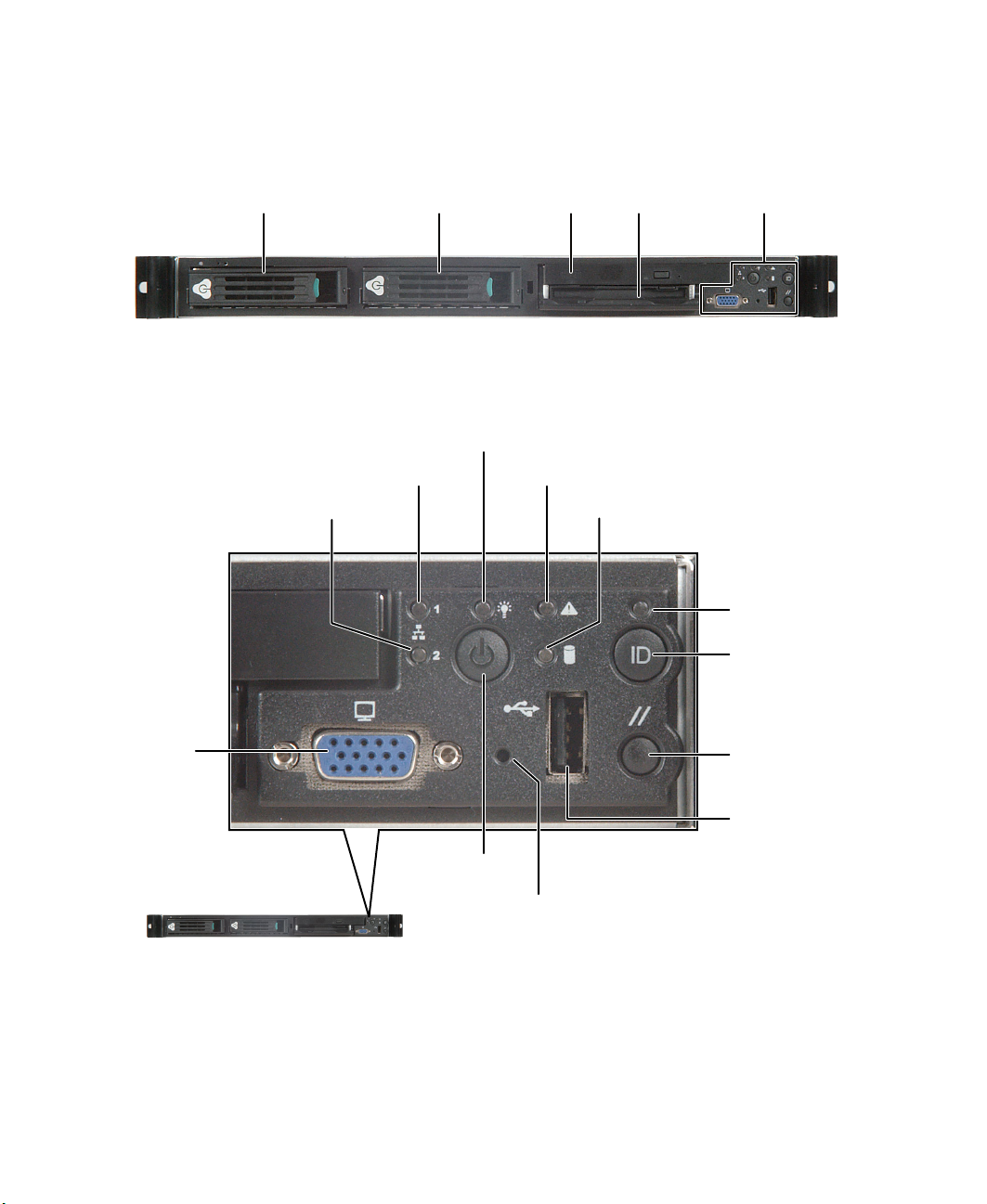
Front
SCSI hard drive 1
Control panel
LAN 1 activity indicator
LAN 2 activity indicator
SCSI hard drive 2
Power in dicato r
Diskette
CD drive
System fault indicator
drive
Hard drive activity indicator
Control
panel
System ID
indicator
System ID
button
VGA
port
Power button
Non-maskable
interrupt button
2
www.gateway.com
Reset
button
USB port
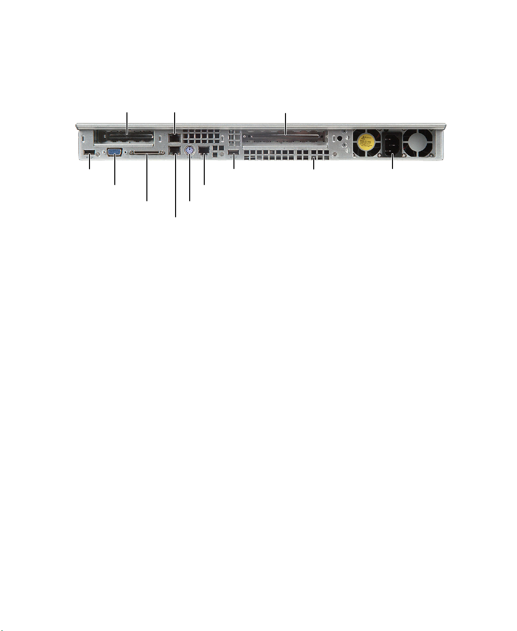
Back
Back
Low-profile PCI
expansion
USB
port
VGA
port
External
SCSI
LAN 2 jack
USB port System ID
Serial RJ-45 port
PS/2 mouse/keyboard port
LAN 1 jack
Full-height PCI
expansion
Power connector
indicator
www.gateway.com
3
Chapter 1: Checking Out Your Gateway Server
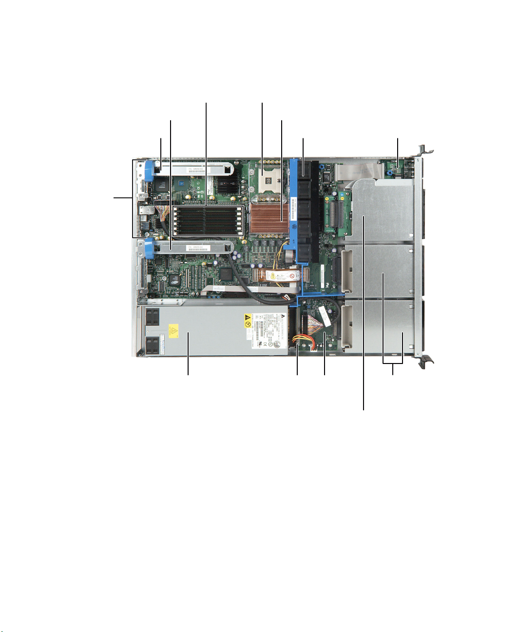
Interior
Low-profile riser
card
I/O ports
Full-height
riser card
Memory slots
Processor 1
Processor 2
Fan module
Front panel
board
Power supply
4
www.gateway.com
Power
distribution
board
SCSI
backplane
Flex bay
Hot-swap SCSI
hard drives
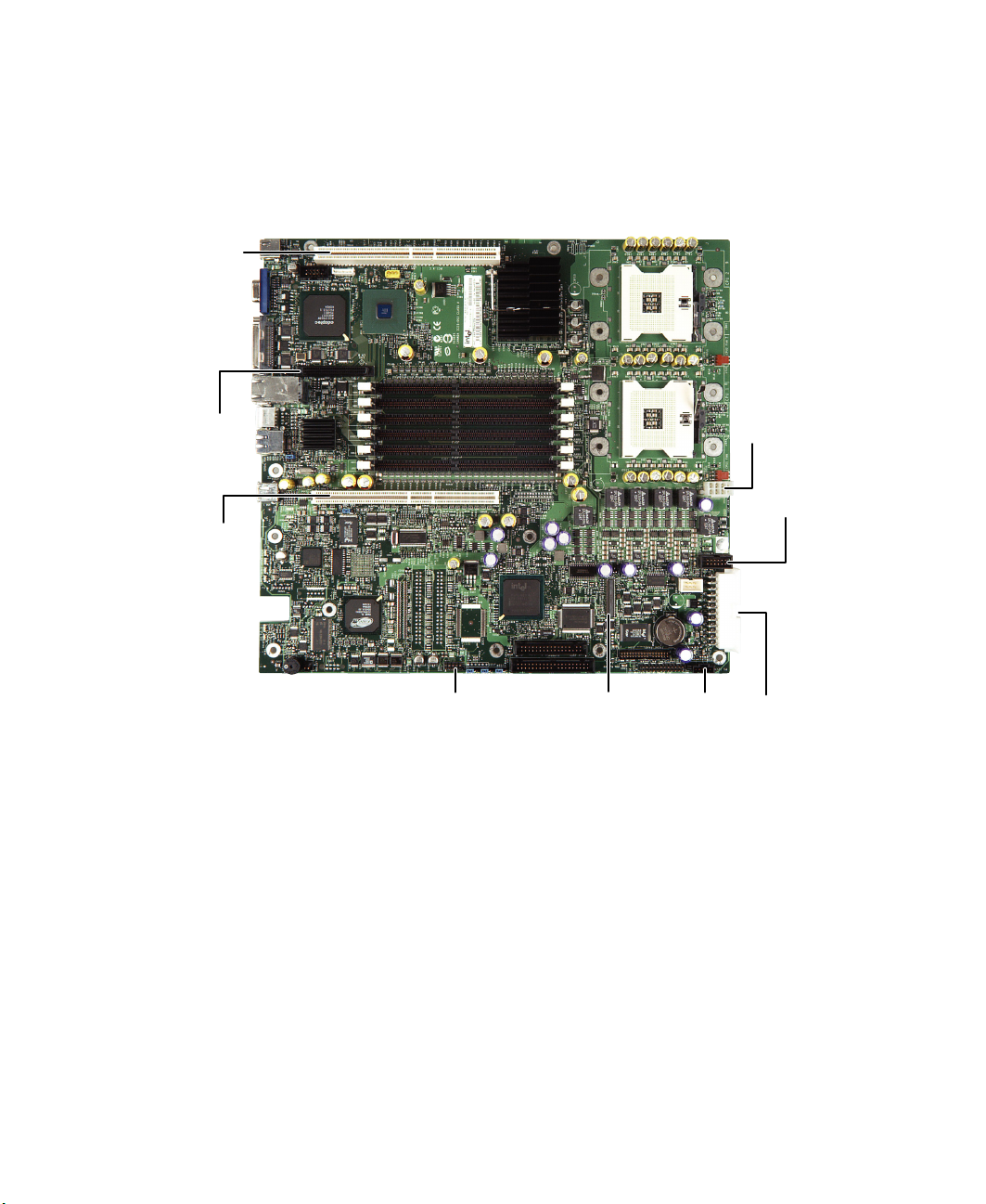
System board
Connectors
PCI riser card
(low-profile)
System board
SCSI
PCI riser card
(full-height)
USB
Diskette/
IDE
Auxiliary
signal
Auxiliary
power
Fan module
power
Main powerFront panel
www.gateway.com
5

Chapter 1: Checking Out Your Gateway Server
Getting Help
In addition to your operating system’s documentation, you can use the
following information resources to help you use your server.
Server Companion CD
Use the Server Companion CD to access file utilities, Windows 2000 Server
drivers, and documentation for your server and its components. For more
information, see Using Your Server Companion CD.
Gateway Web site
Gateway provides a variety of information on its Web site to help you use your
server.
Visit the Gateway Web site at support.gateway.com
■ Technical documentation and product guides
■ Technical tips and support
■ Updated hardware drivers
■ Order status
■ Frequently asked questions (FAQs)
for:
Telephone support
You can access a wide range of services through your telephone, including
customer service, technical support, and information services. For more
information, see “Telephone support” on page 96.
6
www.gateway.com

Setting Up Your
Server
Read this chapter to learn how to:
■ Use your server safely
■ Install your server into a cabinet
■ Start and turn off your server
■ Set up your operating system
2
7

Chapter 2: Setting Up Your Server
Setting up the hardware
To make sure that your working environment is safe:
■ Use a clean, dry, flat, stable surface for your server. Allow at least 6 inches
at the rear of the server for cabling and air circulation.
■ Use the instructions on your server’s setup poster to set up your hardware.
■ Use a grounded (three-prong) surge protector. A surge protector helps
protect against AC power fluctuations. For additional protection from
power outages, we recommend that you use an uninterruptible power
supply (UPS).
Warning Your server comes with a 3-wire AC power cord fitted with
the correct plug style for your region. If this plug does not
match the connector on your surge protector, UPS, or wall
outlet, do not attempt to modify the plug in any way. Use
a surge protector, UPS, or wall outlet that is appropriate
for the supplied AC power cord.
■ Avoid subjecting your server to extreme temperature changes. Do not
expose your server to direct sunlight, heating ducts, or other
heat-generating objects. Damage caused by extreme temperatures is not
covered by your warranty. As a general rule, your server is safest at
temperatures that are comfortable for you.
■ Keep your server and magnetic media away from equipment that
generates magnetic fields, such as unshielded stereo speakers. Strong
magnetic fields can erase data on both diskettes and hard drives. Even a
telephone placed too close to the server may cause interference.
Important Keep the server boxes and packing material in case you
need to ship the server.
8
www.gateway.com

Protecting from power source problems
Protecting from power source
problems
Surge protectors, line conditioners, and uninterruptible power supplies can help
protect your server against power source problems.
Surge protectors
During a power surge, the voltage level of electricity coming into your server
can increase to far above normal levels and cause data loss or server damage.
Protect your server and peripheral devices by connecting them to a surge
protector, which absorbs voltage surges and prevents them from reaching your
server.
Warning High voltages can enter your server through the power
cord, and the modem and network connections. Protect
your server by using a surge protector. If you have a
modem, use a surge protector that has the appropriate
type of modem jack. During an electrical storm, unplug the
surge protector and the modem and network cables.
When you purchase a surge protector:
■ Make sure that the surge protector meets the appropriate product safety
certification for your location, such as Underwriters Laboratories (UL).
■ Check the maximum amount of voltage the protector allows to pass
through the line. The lower the voltage that the protector allows to pass
through, the better the protection for your server.
■ Check the energy absorption (dissipation) rating. The higher the energy
absorption rating, the better the protection for your server.
■ Check for line-conditioner capabilities. A line conditioner smooths out
some of the normal line noise (small voltage fluctuations) of an electrical
supply.
www.gateway.com
9

Chapter 2: Setting Up Your Server
Line conditioners
A line conditioner protects your server from the small fluctuations in voltage
from an electrical supply. Most servers can handle this variation, called line
noise, without problems. However, some electrical sources include more line
noise than normal. Line noise can also be a problem if your server is located
near, or shares a circuit with, a device that causes electromagnetic interference,
such as a television or a motor.
Some surge protectors and uninterruptible power supplies include simple
line-conditioning capabilities.
Uninterruptible power supplies
Use an uninterruptible power supply (UPS) to protect your server from data loss
during a total power failure. A UPS uses a battery to keep your server running
temporarily during a power failure and lets you save your work and shut down
your server. You cannot run your server for an extended period of time while
using only the UPS. To buy a UPS, visit accessories.gateway.com
.
10
www.gateway.com

Mounting your server into a cabinet
Mounting your server into a
cabinet
The cabinet mounting hardware included with your server should be used with
standard 4-post cabinets that have front and back vertical posts. The L-shaped
cabinet mounting brackets can be used for mid-mounting on a 2-post cabinet,
but that procedure is not covered here. If your cabinet is a different type, obtain
mounting hardware from the cabinet manufacturer.
Warning Before attaching cabinet accessories, make sure that
the server is turned off and all power cords are
unplugged.
Warning The cabinet must provide sufficient airflow to the front
of the server to maintain proper cooling. It must also
include ventilation sufficient to exhaust a maximum of
1200 BTUs per hour for this server.
Rackmount kit contents:
■ Server rails (2)
■ Cabinet rails (2)
■ L brackets (2, not used for this type of installation)
■ Fastener pack (1)
■ Small screws (4, #6-32 × 3/16-inch)
■ Medium screws (8, #10-32 × ½-inch)
■ Large screws (2, #10-32 × 7/8-inch)
■ Handle spacers (2)
■ Nut bars (4)
■ Disk guides (2)
www.gateway.com
11
Chapter 2: Setting Up Your Server
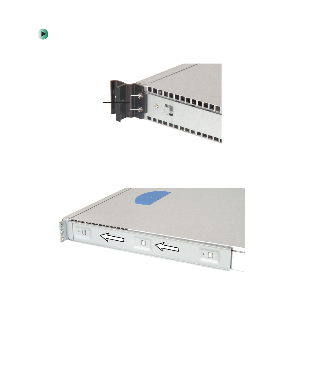
To mount your server in a cabinet:
1 Remove the two screws from each handle, then set the handles and screws
aside.
Screws
2 Align the holes in a server rail with the tabs on the side of the server, then
place the rail against the server and slide the rail as far forward as it will
go. Both server rails are identical, so you can use either rail on either side
of the server.
12
www.gateway.com
Mounting your server into a cabinet
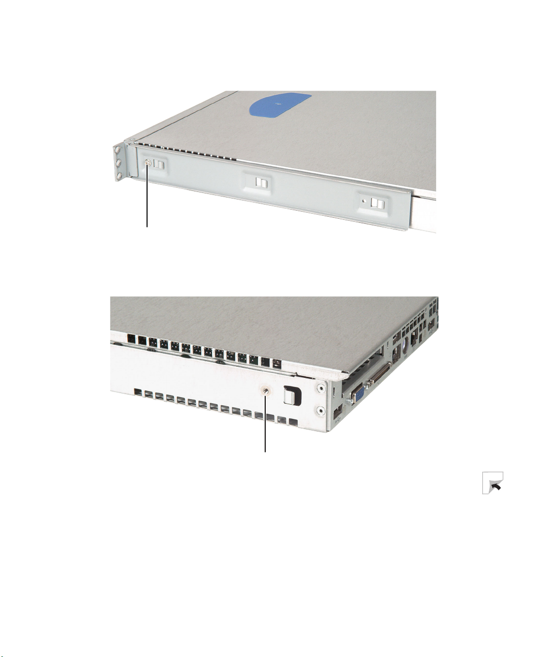
3 Use one of the small screws to fasten the rail to the server, then attach
the remaining rail to the other side of the server.
Screw
4 Place a disk guide over the disk guide screw hole towards the back of the
server.
Screw hole
www.gateway.com
13
Chapter 2: Setting Up Your Server
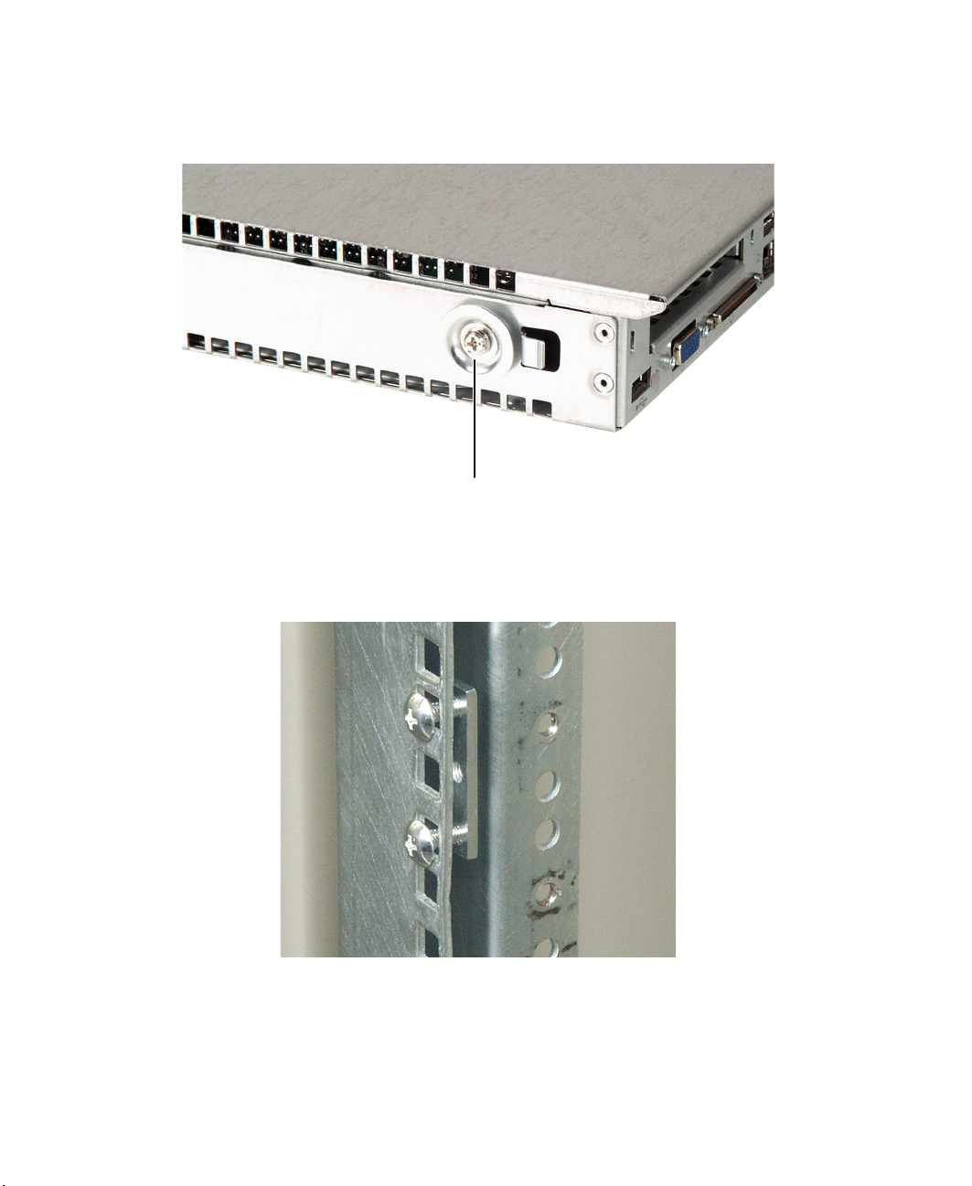
5 Insert a small screw through the disk guide and tighten the screw. Attach
the remaining disk guide to the other side of the server.
6 Attach a nut bar to the inside of the two rear cabinet posts using medium
screws, but do not completely tighten the screws (leave them loose enough
to allow insertion of the cabinet rail in the next step).
Screw
14
www.gateway.com
Mounting your server into a cabinet
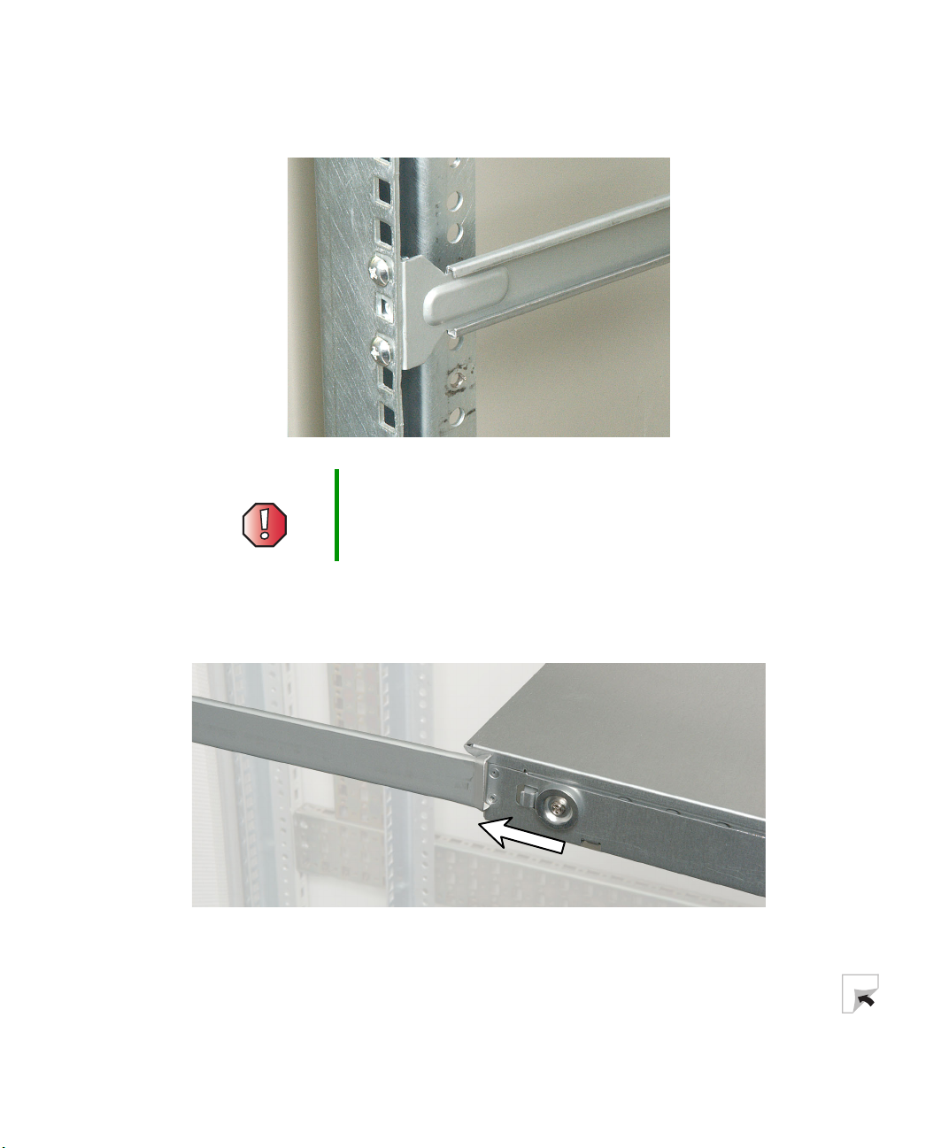
7 Insert the slotted foot of a cabinet rail between each nut bar and post, then
tighten the screws.
Warning Lifting the server and attaching it to the rack is a
two-person job. If needed, use an appropriate lifting
device. A fully loaded Gateway 955 server weighs about
30 lbs. (13.6 kg).
8 With the front of the server facing you, lift the server, insert it into the
cabinet from the front, then position the disk guides so they fit in the
cabinet rails.
9 Push the server toward the back of the cabinet until the front of the server
rails touch the front cabinet posts.
www.gateway.com
15
Chapter 2: Setting Up Your Server
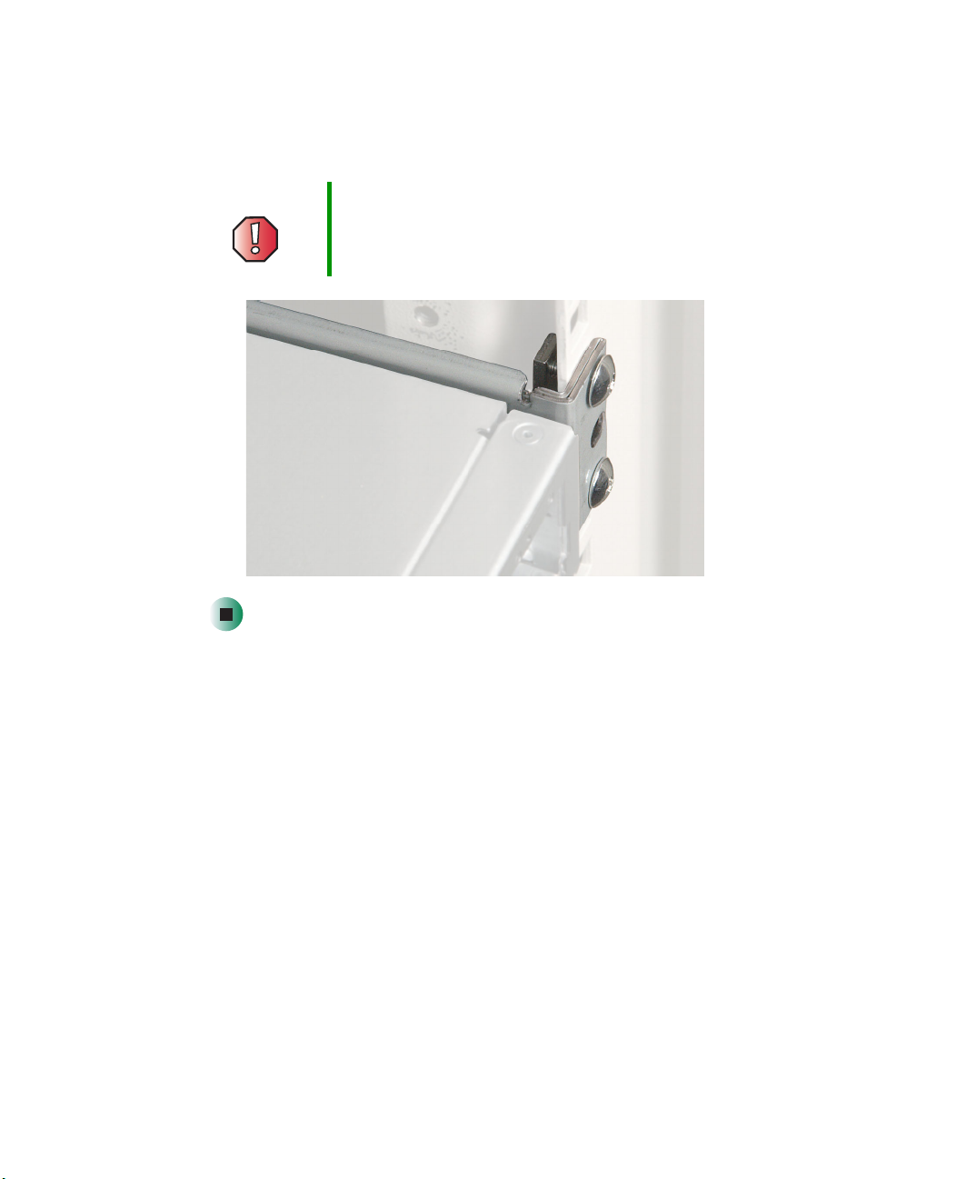
10 Attach one of the server rails to the front cabinet post using two of the
medium screws and one nut bar, then attach the remaining rail to the other
cabinet post.
Warning Screws are required to support the front of the server. You
must support the server while installing or removing the
front screws and while sliding the server on or off the
cabinet rails.
16
www.gateway.com
Installing the front cover
Important The front cover is held in place by the server handles. If
you are not installing the front cover, you do not need to
install the handles.
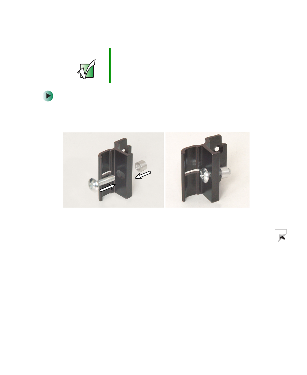
To install the front cover (optional):
1 Insert one of the large screws into the front screw hole on the handle, then
insert a spacer onto the part of the screw protruding from the back of the
handle.
Mounting your server into a cabinet
2 Slide a handle (with its attached screw and spacer) between the server and
the server rail.
www.gateway.com
17
Chapter 2: Setting Up Your Server
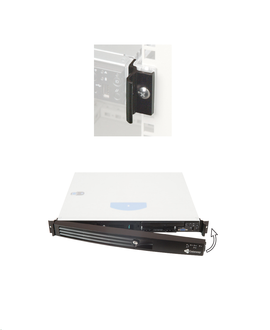
3 Align the screw on the handle with the center hole in the server rail, then
tighten the screw.
4 Attach the remaining handle to the other side of the server.
5 Remove the front cover lock keys from the inside of the front cover, then
snap on the front cover.
18
www.gateway.com
Mounting your server into a cabinet
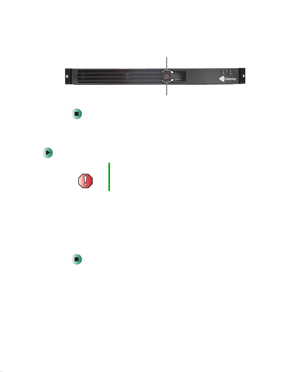
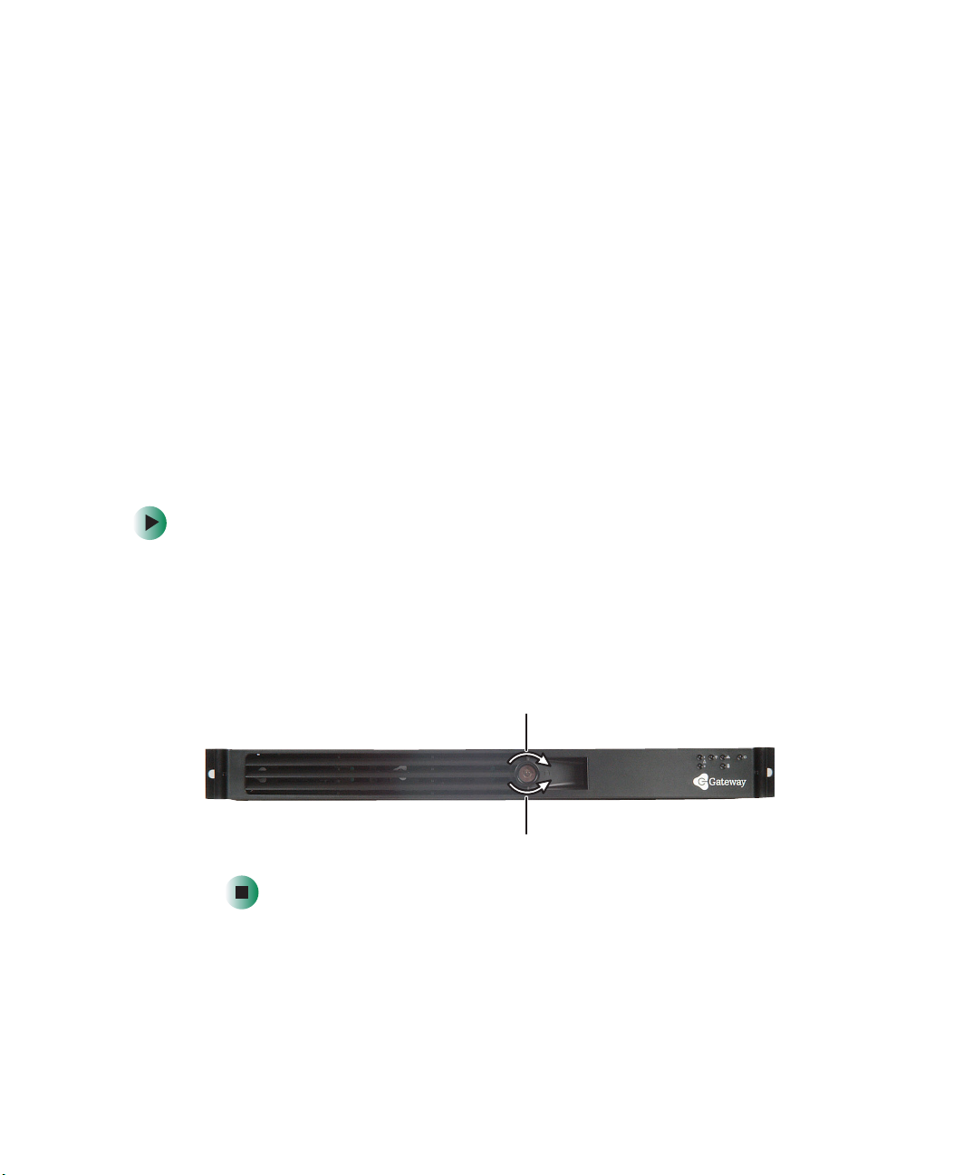
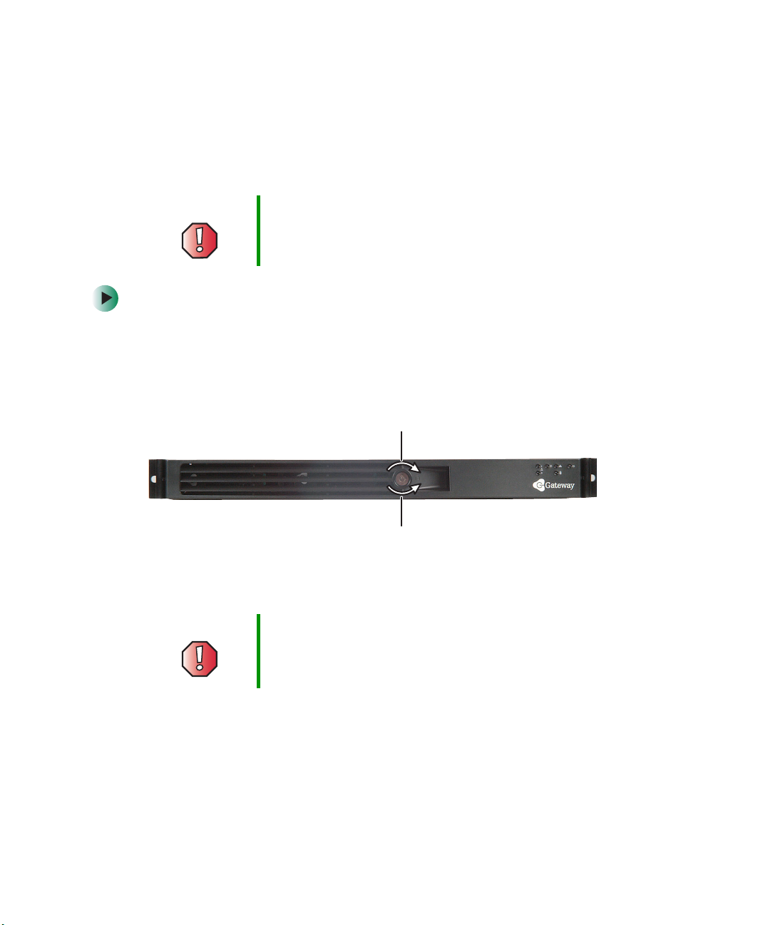
6 To lock the front cover, insert the key into the lock and rotate it ¼ turn
clockwise. To unlock it, rotate the key ¼ turn counter-clockwise.
Lock
Unlock
Removing the server from a cabinet
To remove the server from a cabinet:
Warning Screws are required to support the front of the server. You
must support the server while removing the front screws
and while sliding the server off the cabinet rails.
1 Remove the front cover, if installed.
2 Remove the handles, if installed.
3 While supporting the front of the server, remove the four screws that secure
the server rails to the front cabinet posts.
4 While supporting the server, slide the server away from the cabinet until
it slides off the cabinet rails.
www.gateway.com
19
Chapter 2: Setting Up Your Server
Starting your server
Before you start your server for the first time:
■ Make sure that the server and monitor are plugged into a power outlet or
surge protector and that the surge protector (if you are using one) is turned
on.
■ Make sure that all cables are connected securely to the correct ports and
jacks on the back of the server.
Warning When you connect peripheral devices to the server, make
sure that your server and devices are turned off and the
power cords are unplugged.
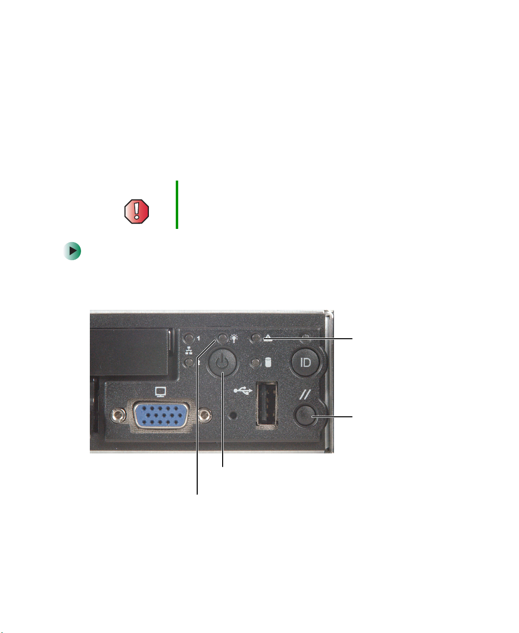
To start the server:
1 Turn on any peripheral devices connected to the server.
2 Press the power button.
20
System fault
indicator
Reset button
Power button
Power indicator
www.gateway.com

Starting your server
When the power
It means...
indicator is...
Green (steady on) The server is turned on.
Green (blinking) The server is in sleep mode.
Off The server is turned off.
When the system
It means...
fault indicator is...
Green (steady on) The server is operating normally.
Green (blinking) The server is operating in a degraded condition.
Orange (steady on) The server is in a critical or unrecoverable condition.
Orange (blinking) The server is in a noncritical condition.
Off POST failure or full system stop.
If nothing happens when you press the power button:
■ Make sure that the power cable is plugged in securely and that your
surge protector (if you are using one) is plugged in and turned on.
■ Make sure that the monitor is connected to the server, plugged into
the power outlet or surge protector, and turned on. You may also need
to adjust the monitor’s brightness and contrast controls.
■ If you cannot find the cause of the power loss, contact Gateway
Technical Support. For more information, see “Getting Help” on
page 6.
3 The first time you turn on the server, any pre-installed operating system
may begin asking you for configuration settings. See your operating
system’s documentation for instructions on configuring advanced settings
for your specific network.
www.gateway.com
21

Chapter 2: Setting Up Your Server
Understanding the power-on self-test
When you turn on your server, the power-on self-test (POST) routine checks
the server memory and components. If POST finds any problems, the server
displays error messages. Write down any error messages that you see, then see
“Error messages” on page 100 and “Beep codes” on page 103 for
troubleshooting information.
Turning off your server
Every time you turn off your server, first shut down the operating system. You
may lose data if you do not follow the correct procedure.
To turn off the server:
1 See the operating system’s documentation or online help for instructions
on shutting down the operating system. Whenever possible, you should
use the operating system’s shut down procedure instead of pressing the
power button.
Warning The power button on the server does not turn off server
AC power. To remove AC power from the server, you must
unplug the AC power cord from the wall outlet or power
source. The power cord is considered the disconnect
device to the main (AC) power.
2 If your server did not turn off automatically, press the power button.
- OR -
Press the reset button to reset the server.
22
www.gateway.com

Setting up the operating system
Setting up the operating system
If you ordered your server with the operating system already installed by
Gateway, it is completely installed and the basic settings are already configured.
See your operating system’s documentation for instructions on configuring
advanced settings for your specific network.
If you are installing an operating system because it was not already installed
by Gateway, see the appropriate installation guide for instructions.
www.gateway.com
23

Chapter 2: Setting Up Your Server
24
www.gateway.com

Maintaining Your
Server
Read this chapter to learn how to:
■ Care for your server
■ Record the BIOS configuration
■ Manage your server and network
3
25

Chapter 3: Maintaining Your Server
Caring for your server
To extend the life of your server:
■ Be careful not to bump or drop your server.
■ When transporting your server, we recommend that you put it in the
original packaging materials.
■ Keep your server and magnetic media away from equipment that generates
magnetic fields, such as unshielded speakers.
■ Avoid subjecting your server to extreme temperatures. Do not expose your
server to heating ducts or other heat-generating objects. Damage caused
by extreme temperatures is not covered by your warranty. As a general rule,
your server is safest at temperatures that are comfortable for you.
■ Keep all liquids away from your server. When spilled onto server
components, almost any liquid can result in extremely expensive repairs
that are not covered under your warranty.
■ Avoid dusty or dirty work environments. Dust and dirt can clog the
internal mechanisms and can cause the server to overheat.
Cleaning your server
Keeping your server clean and the vents free from dust helps keep your server
performing at its best. Your server cleaning kit could include:
■ A soft, lint-free cloth
■ Glass cleaner
■ An aerosol can of air with a narrow, straw-like extension
■ Isopropyl alcohol
■ Cotton swabs
■ A CD drive cleaning kit
26
www.gateway.com

Caring for your server
Cleaning tips
■ Always turn off your server and other peripheral devices before cleaning
any components.
Warning When you shut down your server, the power turns off, but
some electrical current still flows through your server. To
avoid possible injury from electrical shock, unplug the
power cord and all other cables connected to the server.
■ Use a damp, lint-free cloth to clean your server and other parts of your
server system. Do not use abrasive or solvent cleaners because they can
damage the finish on components.
■ Keep the cooling vents free of dust. With your server turned off and
unplugged, brush the dust away from the vents with a damp cloth, but
be careful not to drip any water into the vents.
Cleaning the keyboard
You should clean the keyboard occasionally by using an aerosol can of air with
a narrow, straw-like extension to remove dust and lint trapped under the keys.
If you spill liquid on the keyboard, turn off your server and turn the keyboard
upside down to let the liquid drain. Let the keyboard dry completely before
trying to use it again. If the keyboard does not work after it dries, you may
need to replace it. Keyboard damage resulting from spilled liquids is not covered
by your warranty.
Cleaning the screen
If your computer screen is a flat panel display, use only a damp, soft cloth to
clean it. Never spray water directly onto the screen.
Warning The computer screen is made of specially coated glass
and can be scratched or damaged by abrasive or
ammonia-based glass cleaners.
- OR -
If your computer screen is not a flat panel display, use a soft cloth dampened
with glass cleaner to clean the screen. Never spray cleaner directly onto the
screen.
www.gateway.com
27

Chapter 3: Maintaining Your Server
Preparing for system recovery
If your system files are corrupted, you may not be able to start the server from
the hard drive. Startup diskettes are diskettes that let you start the server and
attempt to fix the problem. See your operating system’s documentation or
online help for instructions on creating startup diskettes.
Some operating systems also let you create an emergency repair diskette to back
up critical operating system files. See your operating system’s documentation
or online help for instructions on creating and using an emergency repair
diskette.
Recording the BIOS configuration
To help keep track of your custom changes to BIOS settings and to prepare for
system recovery, you should record your BIOS configuration after you have your
server set up and working.
To record your BIOS configuration:
28
1 Print the appendix for “BIOS Settings” on page 119.
2 Restart your server, then press F2 when the Gateway logo screen appears
during startup. The BIOS Setup utility opens.
3 Record the BIOS settings on your printout.
www.gateway.com
System administration
System administration
Gateway Server Manager
Gateway Server Manager lets you manage multiple computers on a Windows™
network from a single window, then implement commands and policies across
the network with a single action. With Gateway Server Manager, you can run
system management tasks which are triggered by certain events or conditions.
Printed documentation comes with the Gateway Server Manager CD. You can
find additional documentation in the program’s online help.
Server security
Locking the server
To lock the server:
1 Remove the front cover lock keys from the inside of the front cover, then
snap on the front cover. The handles must be installed for the cover to
snap on. For instructions, see “Installing the front cover” on page 17.
2 Insert the key into the lock and rotate it ¼ turn clockwise. To unlock it,
rotate the key ¼ turn counter-clockwise.
Lock
Unlock
www.gateway.com
29

Chapter 3: Maintaining Your Server
Using BIOS security passwords
To prevent unauthorized use of the server, you can set server startup passwords.
Set up an administrator password to prevent unauthorized access to the BIOS
Setup utility.
For information about resetting BIOS passwords, see “Resetting BIOS
passwords” on page 93.
To set the BIOS security passwords:
1 Restart your server, then press F2 when the Gateway logo screen appears
during startup. The BIOS Setup utility opens.
2 Select the Security menu.
3 Select Administrator Password.
4 Type the password and press ENTER, then type it again and press ENTER.
5 Save your changes and close the BIOS Setup utility.
To remove a BIOS security password:
1 Restart your server, then press F2 when the Gateway logo screen appears
during startup. The BIOS Setup utility opens.
2 Select the Security menu, then select the password to remove.
3 Enter the current password, then press ENTER.
4 For the new password, leave the password field blank, then press ENTER.
The password is removed.
Tips & Tricks Passwords can also be cleared using jumpers on the
system board. For instructions, see “Resetting BIOS
passwords” on page 93.
30
www.gateway.com

Using your Server Companion CD
Using your Server Companion CD
You can use your Server Companion CD to:
■ Install hardware drivers
■ Install programs
■ View server documentation
Instructions for using the CD are provided in Using Your Server Companion CD.
www.gateway.com
31
Chapter 3: Maintaining Your Server
Identifying your server
While you are working on a cabinet that contains several slim servers, it can
be difficult to keep track of which server or servers you are currently working
on. The System ID indicator is a blue LED that you can turn on to help you
locate the correct server. Your server has a System ID indicator in the front and
in the back.
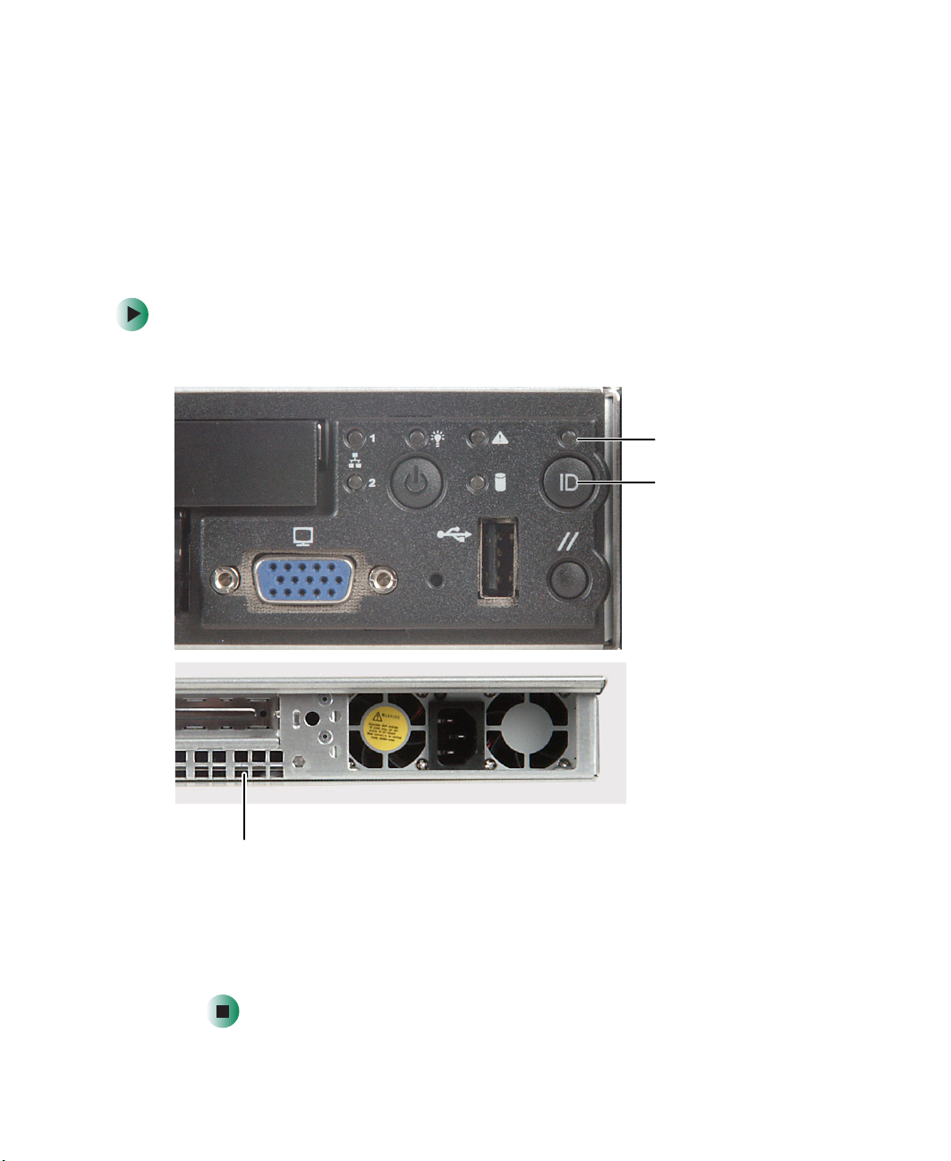
To turn on the System ID indicator:
1 Press the System ID button. The two blue System ID indicators turn on.
System ID
indicator
System ID
button
32
System ID
indicator
For the System ID indicator to turn on, the server does not need to be
turned on, but it does need to be plugged in.
2 To turn off the indicator, press the System ID button.
www.gateway.com

Updating the baseboard management controller firmware
Updating the baseboard
management controller firmware
The baseboard management controller (BMC) performs several system
management functions such as:
■ Monitoring server components and sensors
■ Managing nonvolatile storage for the system event log and sensor data
records
■ Interfacing with the emergency management port (RJ-45 serial on back
panel) and LAN 1 port to send alerts and interact with remote management
systems.
■ Providing the main front panel controls (such as power and reset).
You should update the BMC firmware when Gateway Technical Support has
instructed you to update it.
www.gateway.com
33
Chapter 3: Maintaining Your Server
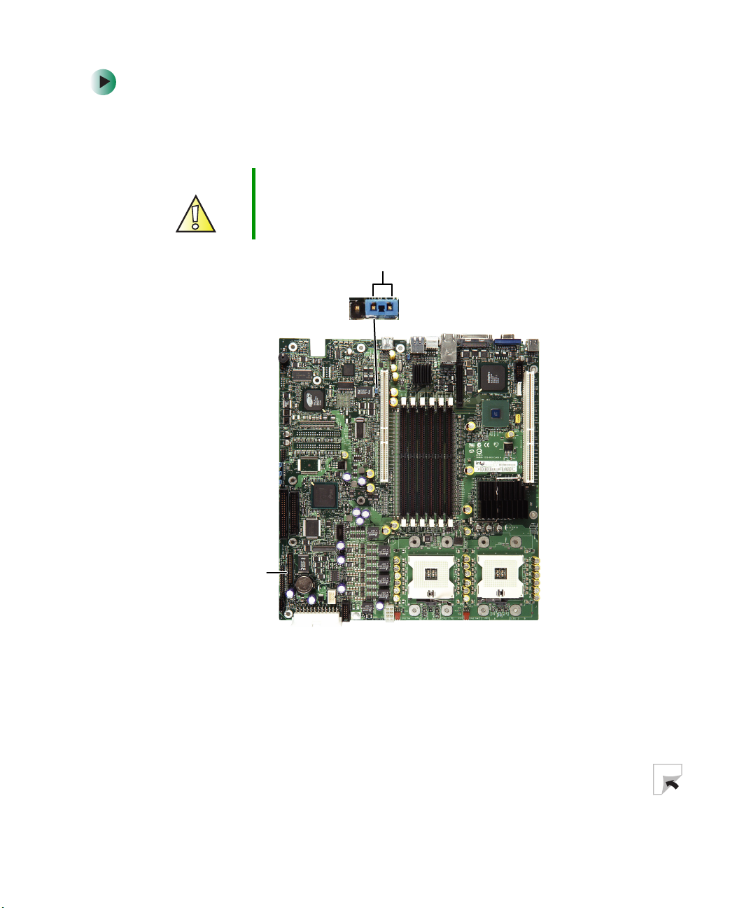
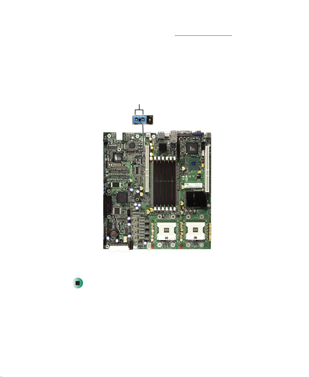
To update the BMC firmware:
1 Follow the instructions in “Preventing static electricity discharge” on
page 45. Make sure that you disconnect the power cord, and wait until the
Standby power LED turns off.
Caution If you do not disconnect the power cord when instructed
to in this procedure, the BMC firmware will not update.
Pins 1-2
34
Standby
power LED
2 Follow the instructions in “Opening the server case” on page 46.
3 Move the BMC Write Enable jumper to pins 1-2.
4 Follow the instructions in “Closing the server case” on page 48, then
reconnect the power cord.
5 Create a DOS-bootable diskette.
www.gateway.com
Updating the baseboard management controller firmware
6 Download the BMC update file from support.gateway.com.
7 Follow the instructions included with the update file.
8 Turn off the server, then disconnect the power cord and wait for the
Standby power LED to turn off.
9 Follow the instructions in “Opening the server case” on page 46.
10 Move the BMC Write Enable jumper back to pins 2-3.
Pins 2-3
11 Follow the instructions in “Closing the server case” on page 48, then
reconnect the power cord.
www.gateway.com
35

Chapter 3: Maintaining Your Server
Using the System Setup Utility
The System Setup Utility (SSU) lets you:
■ View FRU information
■ View sensor data records
■ Set up the server to send alerts for platform events
■ Set up the server for out-of-band (OOB) access through Gateway Server
Manager
Important The SSU does not work within a DOS window running
under an operating system such as Windows.
Viewing FRU information
To view the Field Replaceable Unit (FRU) information:
1 Boot your server from the Server Companion CD, then select System Setup
Utility
from the menu. The System Setup Utility starts.
2 From the SSU Main window, click FRU Manager. The SSU automatically loads
the current list of events from non-volatile memory.
3 Click the category for Chassis, Board, or Product. The category expands to
show a list of components for that category.
4 Click a component. Information for that component is displayed.
36
www.gateway.com

Using the System Setup Utility
Viewing sensor data records
To view the Sensor Data Records (SDR):
1 Boot your server from the Server Companion CD, then select System Setup
Utility
from the menu. The System Setup Utility starts.
2 In the SSU Main window, click SDR Manager.
3 Click a category in the left pane. The category expands to show a list of
SDRs for that category.
4 Click an SDR. Information for that SDR is displayed.
Setting up remote access
You can set up the server so that you can perform system management tasks
remotely.
Setting up remote LAN access
To set up remote LAN access:
1 Boot your server from the Server Companion CD, then select System Setup
Utility
from the menu. The System Setup Utility starts.
2 In the SSU Main window, click Platform Event Manager (PEM).
3 In the PEM window, click Configure LAN.
4 To require a password for remote access, type the password in the Enter
New Password
from 1 to 16 characters long, using any ASCII character in the range 32-126.
To clear the password, leave both boxes blank. You can also clear the
password by clicking
box and in the Verify New Password box. Passwords can be
Options, then Clear LAN Password.
www.gateway.com
37

Chapter 3: Maintaining Your Server
5 Click the remote access mode from the LAN Access Mode list:
■ Always Available—A remote system can initiate a LAN connection
regardless of the state of the server.
■ Restricted—A remote system can initiate a LAN connection, but
cannot perform control operations such as turn off power, reset, or
front panel NMI (non-maskable interrupt).
■ Disabled—Remote systems are not allowed to initiate LAN
connections.
6 In the IP Setup box, click one:
■ DHCP—The IP address for the server is automatically assigned by the
DHCP (dynamic host control protocol) server on the network. The
Host, Gateway, and Subnet Mask boxes in the dialog box are ignored.
■ Static—Assign the IP address for the server using the Host, Gateway,
and Subnet Mask boxes in the dialog box.
7 If you selected Static in the previous step, complete the IP addressing boxes:
■ Host IP Address—The IP address of this server.
■ Gateway IP Address—The IP address of the router for this server.
■ Subnet Mask—The IP address for the server's subnet. The server uses
this to decide if the alert destination is on the same subnet.
8 Click Save to save the changes.
9 Click Close to return to the PEM window.
Setting up remote modem or serial access
To set up remote modem or serial access:
1 Boot your server from the Server Companion CD, then select System Setup
Utility
from the menu. The System Setup Utility starts.
2 In the SSU Main window, click Platform Event Manager (PEM).
3 In the PEM window, click Configure EMP.
38
www.gateway.com

Using the System Setup Utility
4 To require a password for remote access, type the password in the Enter
New Password
from 1 to 16 characters long, using any ASCII character in the range 32-126.
To clear the password, leave both boxes blank. You can also clear the
password by clicking
box and in the Verify New Password box. Passwords can be
Options, then Clear LAN Password.
5 In the Modem Ring Time box, type the number of 500 ms intervals that the
BMC should wait before answering an incoming call. A value greater than
zero gives the BIOS time to answer before the BMC takes control. A value
of zero causes the BMC to answer immediately. The maximum value, 63,
tells the BMC to ignore the call. Modem Ring Time applies only to Preboot
access mode and is ignored for other access modes.
6 In the System Phone Number box, type the number for the phone line
connected to the modem on the EMP.
7 In the Access Mode list, click the remote access mode:
■ Always Active—The EMP is available at any time.
■ Preboot—The EMP is available only when the server is powered down
or is running POST during startup. After the operating system is
loaded, a connection cannot be made.
■ Disabled—Remote systems are not allowed to initiate connections.
8 In the Restricted Mode list, click either:
■ Enabled—A remote system can initiate a connection, but cannot
perform control operations such as power down, reset, or front panel
NMI.
■ Disabled—The remote system has full control of the server.
9 In the Connection Mode list, click either:
■ Direct Connect—The Serial RJ-45 port on the server is connected by a
serial cable to the remote system.
■ Modem Connect—The Serial RJ-45 port on the server is connected to
a modem.
10 Click Save to save the changes.
11 Click Close to return to the PEM window.
www.gateway.com
39

Chapter 3: Maintaining Your Server
Setting up paging alerts
To set up paging alerts:
1 Boot your server from the Server Companion CD, then select System Setup
Utility
from the menu. The System Setup Utility starts.
2 Install an external modem on the serial RJ-45 port on the back of your
server.
3 In the SSU Main window, click Platform Event Manager (PEM).
4 In the PEM window, click Configure EMP.
5 In the corresponding boxes, enter the following command strings for the
modem attached to the serial RJ-45 port:
■ ESC Sequence—The escape sequence. This string is sent to the modem
before sending command strings. The maximum length for the string
is five characters. Longer strings are truncated.
■ Hangup String—Hang up or drop the connection. The EMP
automatically sends an E
maximum length for the string is eight characters.
NTER character following this string. The
■ Modem Dial Command—The command to dial a phone number. This
string is sent to the modem before sending the paging string.
■ Modem Init String—Initialization string for the modem. Sent every time
the EMP initializes. You will be notified if the string is truncated.
Following a save, the actual string saved is displayed in the edit box.
6 Click Save to save the changes.
7 Click Close to return to the PEM window.
8 In the PEM window, click Configure PEP.
9 Click to select the Enable PEP check box.
10 In the Blackout Period box, type the minimum time, in minutes, between
successive pages. The valid range is 0-255 where 0 disables the blackout
period.
Setting a blackout period can save you from being flooded with repeat
pages. After you receive a PEP page, no additional pages are sent by PEP
for the duration of the blackout period.
40
www.gateway.com

Using the System Setup Utility
11 In the Paging String box, type the telephone number to dial for the page
and the message you want sent with the page. The maximum length for
the paging string is determined at runtime from firmware. You will be
notified if the string is truncated. Following a save, the actual string saved
is displayed in the edit box.
12 Click Options, then click Configure Event Actions.
13 In the Platform Event Paging Actions window, move the events that you want
to generate an alert to the
the
Disabled column using the following buttons:
■ >> Moves all events from the Enabled list to the Disabled list.
■ > Moves the selected event from the Enabled list to the Disabled list.
■ < Moves the selected event from the Disabled list to the Enabled list.
■ << Moves all events from the Disabled list to the Enabled list.
Enabled column and move all other events to
14 Click Save to save the changes.
15 Click Close to return to the PEP Configuration window.
16 To send a test page to verify that you have correctly configured PEP, click
Options, then click Send Alert.
17 Click Save to save the configuration.
18 Click Close to return to the Platform Event Manager window.
Setting up LAN alerts
To set up LAN alerts:
1 Boot your server from the Server Companion CD, then select System Setup
Utility
from the menu. The System Setup Utility starts.
2 In the SSU Main window, click Platform Event Manager (PEM).
3 In the PEM window, click Configure LAN.
4 Click to select the Enable LAN Alerts check box.
www.gateway.com
41

Chapter 3: Maintaining Your Server
5 In the SNMP Community String box, you can type an optional string for the
community field in the
The string must be from 5 to 16 characters. The default string is public.
6 In the IP Setup box, click either:
■ DHCP—The IP address for the server is automatically assigned by the
DHCP (dynamic host control protocol) server on the network. The
Host, Gateway, and Subnet Mask boxes in the dialog box are ignored.
■ Static—Assign the IP address for the server using the Host, Gateway,
and Subnet Mask boxes in the dialog box.
7 If you chose Static IP Setup in the previous step, complete the IP addressing
boxes:
■ Host IP Address—The IP address of this server.
■ Gateway IP Address—The IP address of the router for this server.
■ Subnet Mask—The IP address for the server’s subnet. The server uses
this to decide if the alert destination is on the same subnet.
8 In the Alert IP Address box, complete the IP address of the system you want
to receive alerts from this server. If you want the alert to be broadcast to
an entire subnet, enter the IP address for the subnet.
Header section of the SNMP trap sent for an alert.
9 Click Options, then click Configure Event Actions.
10 In the BMC LAN Alerting Actions window, move the events that you want
to generate an alert to the
the
Disabled column using the following buttons:
■ >> Moves all events from the Enabled list to the Disabled list.
■ > Moves the selected event from the Enabled list to the Disabled list.
■ < Moves the selected event from the Disabled list to Enabled the list.
■ << Moves all events from the Disabled list to the Enabled list.
Enabled column and move all other events to
11 Click Save to save the changes.
12 Click Close to return to the BMC LAN Configuration window.
13 Click Save to save the changes.
14 Click Close to return to the PEM window.
42
www.gateway.com

Installing
Components
Read this chapter to learn how to:
■ Open and close the server case
■ Install drives
■ Install expansion cards and memory modules
■ Install processors
■ Replace the power supply
■ Replace the SCSI backplane
■ Replace the fan module
■ Replace the front panel board and power distribution
board
■ Replace the system board and CMOS battery
You must open your server case to install components. If
you are not comfortable with these procedures, get help
from a computer service technician or contact Gateway
Technical Support.
4
43

Chapter 4: Installing Components
Preparing to install components
Selecting a place to work
Work on your server in an area that:
■ Is clean (avoid dusty areas)
■ Is a low-static environment (avoid carpeted areas)
■ Has a stable surface on which to set your server
■ Has enough room to place all of your server parts
■ Is near a grounded outlet so you can test your server after installation
■ Is near a telephone (in case you need help from Gateway Technical
Support). The telephone must be directly connected to a telephone jack
and cannot be connected to your server.
Gathering the tools you need
Some tools and supplies that you may need to work on your server are:
■ A notebook to take notes
■ A Phillips screwdriver
■ A small flat-blade screwdriver
■ Small containers to store various types of screws
■ A grounding wrist strap (available at most electronic stores)
Getting Help
If you have questions about performing any of these procedures, contact
Gateway Technical Support. For more information, see “Getting Help” on
page 6.
44
www.gateway.com

Preventing static electricity discharge
Preventing static electricity
discharge
The components inside your server are extremely sensitive to static electricity,
also known as electrostatic discharge (ESD).
Warning ESD can permanently damage electrostatic
discharge-sensitive components in the server. Prevent
ESD damage by following ESD guidelines every time you
open the server case.
Warning To avoid exposure to dangerous electrical voltages and
moving parts, turn off your server and unplug the power
cord and modem cable before opening the server case.
Before working with server components, follow these guidelines:
■ Turn off the server, then unplug the power cords and all other cables.
■ Press the power button to drain any residual power from the server.
■ Wear a grounding wrist strap (available at most electronics stores) and
attach it to a bare metal part of the server. You can also touch a bare metal
surface on the back of the server with your finger.
Warning To prevent risk of electric shock, do not insert any object
into the vent holes of the power supply.
■ Avoid static-causing surfaces such as carpeted floors, plastic, and packing
foam.
■ Avoid working on the server when your work area is extremely humid.
■ Remove components from their antistatic bags only when you are ready
to use them. Do not lay components on the outside of antistatic bags
because only the inside of the bags provide electrostatic protection.
■ Always hold expansion cards by their edges or their metal mounting
brackets. Avoid touching the edge connectors and components on the
cards. Never slide expansion cards or components over any surface.
www.gateway.com
45
Chapter 4: Installing Components
Opening the server case
Because the components inside your server are extremely sensitive to static
electricity, make sure that you follow the instructions at the beginning of this
chapter to avoid static electricity damage.
Warning For correct cooling and air flow, always reinstall the top
panel before you turn on the server. Operating the server
without the panel in place will cause the server to overheat.
To open the server:
1 Follow the instructions in “Preventing static electricity discharge” on
page 45. Make sure you turn off the server, then unplug the power cord
and all other cables connected to the server.
2 If the front cover is installed, unlock it, then pull it off.
Lock
46
Unlock
3 If the server is mounted in a cabinet, remove the server from the cabinet.
For instructions, see “Removing the server from a cabinet” on page 19.
Warning Screws are required to support the front of the server when
using the standard cabinet rails. You must support the
server while removing the front screws and while sliding
the server off the cabinet rails.
4 Place the server on a stable, non-skid surface.
www.gateway.com

Opening the server case
5 Press and hold the panel release button, then slide the top panel toward
the back of the server about 1/2 inch.
Panel release
button
6 Lift the top panel away from the server.
www.gateway.com
47

Chapter 4: Installing Components
Closing the server case
To close the server case:
1 Make sure that all of the internal cables are arranged inside the case so
they will not be pinched when you close the case.
2 Slide the top panel’s edges into the server.
3 Slide the top panel toward the front of the server until it clicks into place.
4 Reconnect the power cord and all other cables.
48
www.gateway.com
Installing drives
Your server’s basic configuration includes one combination CD/diskette drive
and as many as three SCSI hard drives.
As you prepare to install drives, remember:
■ Before you install a drive, see the drive’s documentation for information
on configuring the drive, setting drive jumpers, and attaching cables.
■ You may need to configure the drives you install using the BIOS Setup
utility. Press F2 at startup to open the BIOS Setup utility.
Replacing the CD/diskette drive in the Flex Bay
To replace the drive in the Flex Bay:
1 Follow the instructions in “Preventing static electricity discharge” on
page 45.
Installing drives
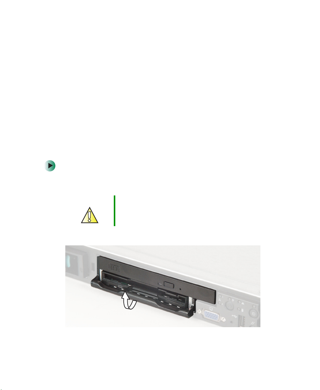
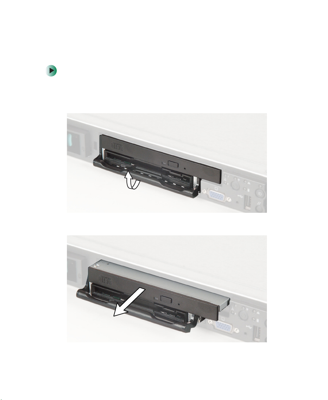
Caution The combination CD/diskette drive is not hot-swappable.
Before removing the drive, make sure that power is turned
off.
2 Rotate the combination drive’s locking handle up.
www.gateway.com
49
Chapter 4: Installing Components
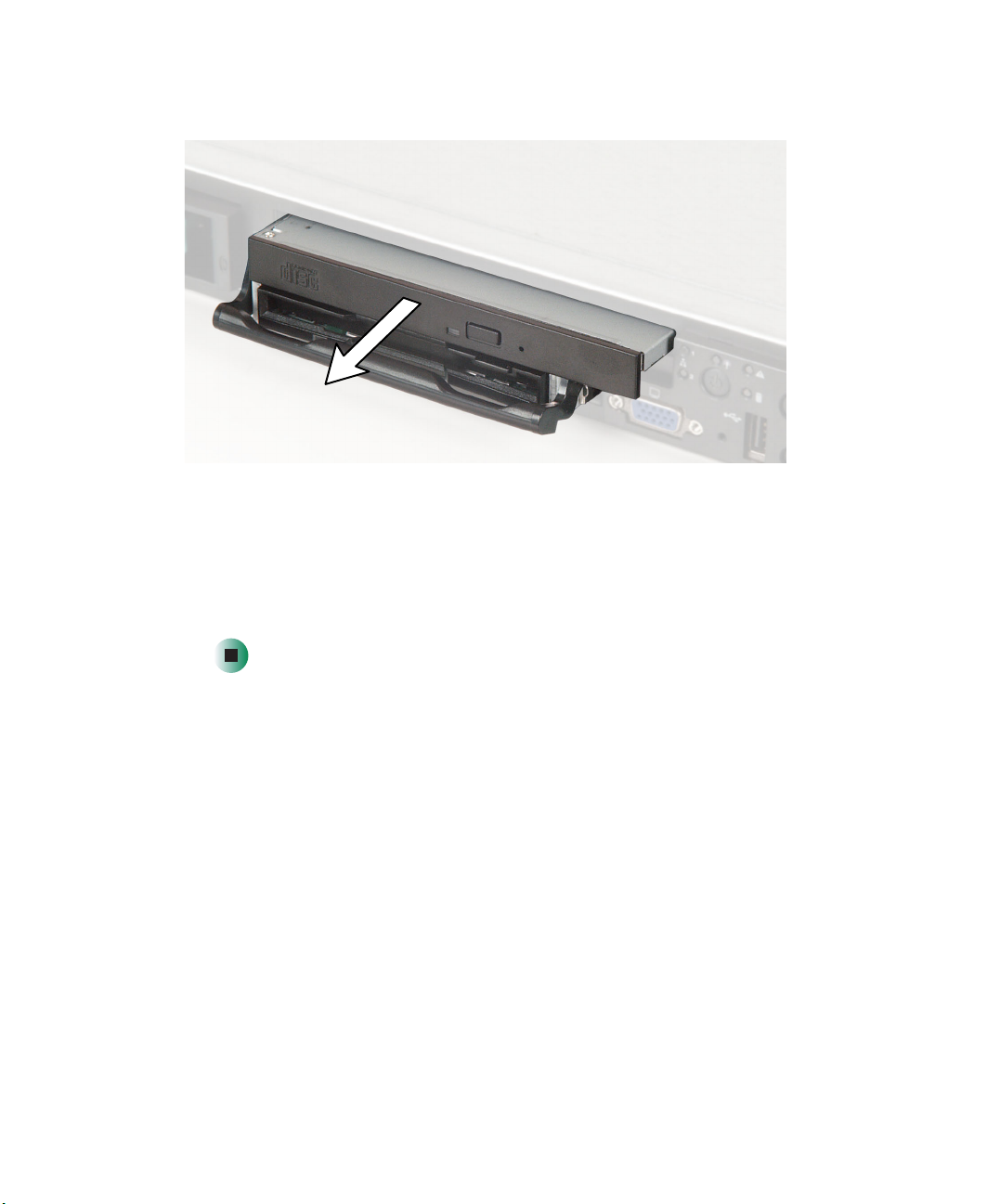
3 While holding the locking handle, pull the drive out of the server.
4 Insert the new drive into the Flex Bay, then press it in until the drive
faceplate is flush with the front of the server.
5 Rotate the locking handle down.
50
6 Reconnect all power cords and peripheral device cables, then turn on the
server.
www.gateway.com
Installing drives
Installing a hot-swap SCSI hard drive into the Flex Bay
To install a hot-swap hard drive into the Flex Bay:
1 Follow the instructions in “Preventing static electricity discharge” on
page 45.
2 Rotate the combination drive’s locking handle up.
3 While holding the locking handle, pull the drive out of the server.
www.gateway.com
51

Chapter 4: Installing Components
4 Insert the Flex Bay plug into the top left area of the front control panel.
The Flex Bay plug comes in your server’s accessory box.
5 Install the hard drive into the hot-swap drive tray. For instructions, see
“Installing a hard drive” on page 54.
52
6 Make sure that the tray’s release lever is fully open, then slide the tray and
drive into the Flex Bay.
www.gateway.com

Installing drives
7 Press the lever closed to lock the drive into place.
8 Reconnect all power cords and peripheral device cables, then turn on the
server. After the hard drive is installed and the server is turned on, the hard
drive in the Flex Bay is hot-swappable.
www.gateway.com
53

Chapter 4: Installing Components
Installing a hard drive
Use this procedure to add or replace hard drives in the hot-swap bay. Your server
supports up to three 1-inch high 3.5-inch SCA SCSI hard drives. You can
purchase additional SCSI drives through your Gateway sales or Technical
Support representative.
Important Gateway tests and verifies the operation and compatibility
To install a hard drive:
1 Remove the front cover (if installed).
Caution Before you remove a failed drive, use the appropriate
of the drives it sells. Especially in a hot-swap or
mission-critical environment, additional or replacement
drives must conform to Gateway standards.
software and utilities installed on the server to stop all
activity on the failed drive. Instructions for using the
software are provided by the software manufacturer.
Failure to do so may destroy the data on the drive.
54
www.gateway.com

Installing drives
2 Press the green release button on the hot-swap tray lever, then swing the
lever open all the way.
3 Pull the tray straight out of the server.
www.gateway.com
55

Chapter 4: Installing Components
4 If you are replacing a hard drive, remove the four screws that secure the
old hard drive to the drive tray, then remove the drive from the tray.
Screw
- OR -
If you are adding a new drive, remove the four screws that secure the hard
drive spacer to the drive tray, then remove the spacer from the tray.
Screw
Screw
Screw
56
Screw
Screw
Screw
Screw
www.gateway.com

Installing drives
5 Line up the screw holes in the new drive with the holes in the side of the
drive tray, then secure the drive to the tray with the four screws you
removed in Step 4.
6 Make sure that the tray’s release lever is open, then slide the new drive
into the empty hot-swap bay.
7 Close the drive’s release lever.
www.gateway.com
57
Chapter 4: Installing Components
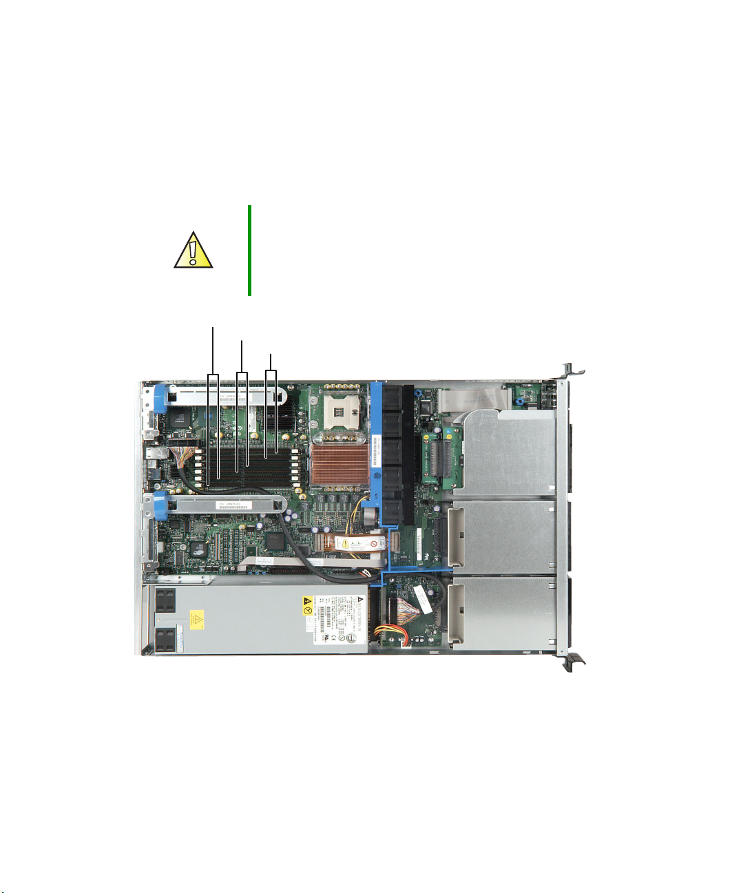
Installing memory
Modules must be installed in identical pairs. Use only low-profile (LP) 1.2-inch,
DDR-266 compliant, SDRAM registered ECC, DIMM memory modules. First
install modules into Bank 1, then Bank 2, then Bank 3. Supports up to 12 GB
total memory.
Caution Modules must be installed in identical pairs. Use only
low-profile (LP) 1.2-inch, DDR-266 compliant, SDRAM
registered ECC, DIMM memory modules.
Install memory first into Bank 1, Bank 2, then Bank 3. If
memory is installed incorrectly, your server will not start.
Bank 1
Bank 2
Bank 3
58
www.gateway.com
Installing memory
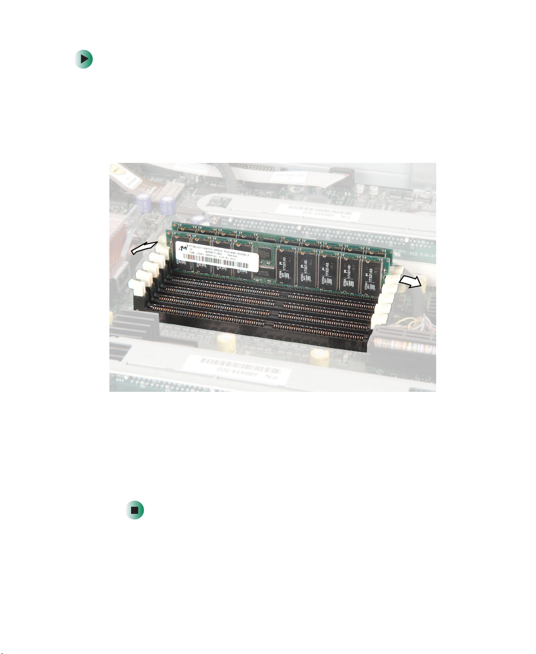
To install or replace memory:
1 Follow the instructions in “Preventing static electricity discharge” on
page 45.
2 Follow the instructions in “Opening the server case” on page 46.
3 Pull the plastic tabs away from the sides of the memory module slot. If
you are replacing a memory module, lift the old module out of the slot.
4 Align the notch on the new module with the notch in the memory module
slot and press the module firmly into the slot. The tabs on the sides of
the memory slot should secure the memory module automatically.
5 Follow the instructions in “Closing the server case” on page 48.
6 Turn on the server, then make sure that the operating system completely
loads. If you receive an error, see “Memory” on page 108.
www.gateway.com
59
Chapter 4: Installing Components
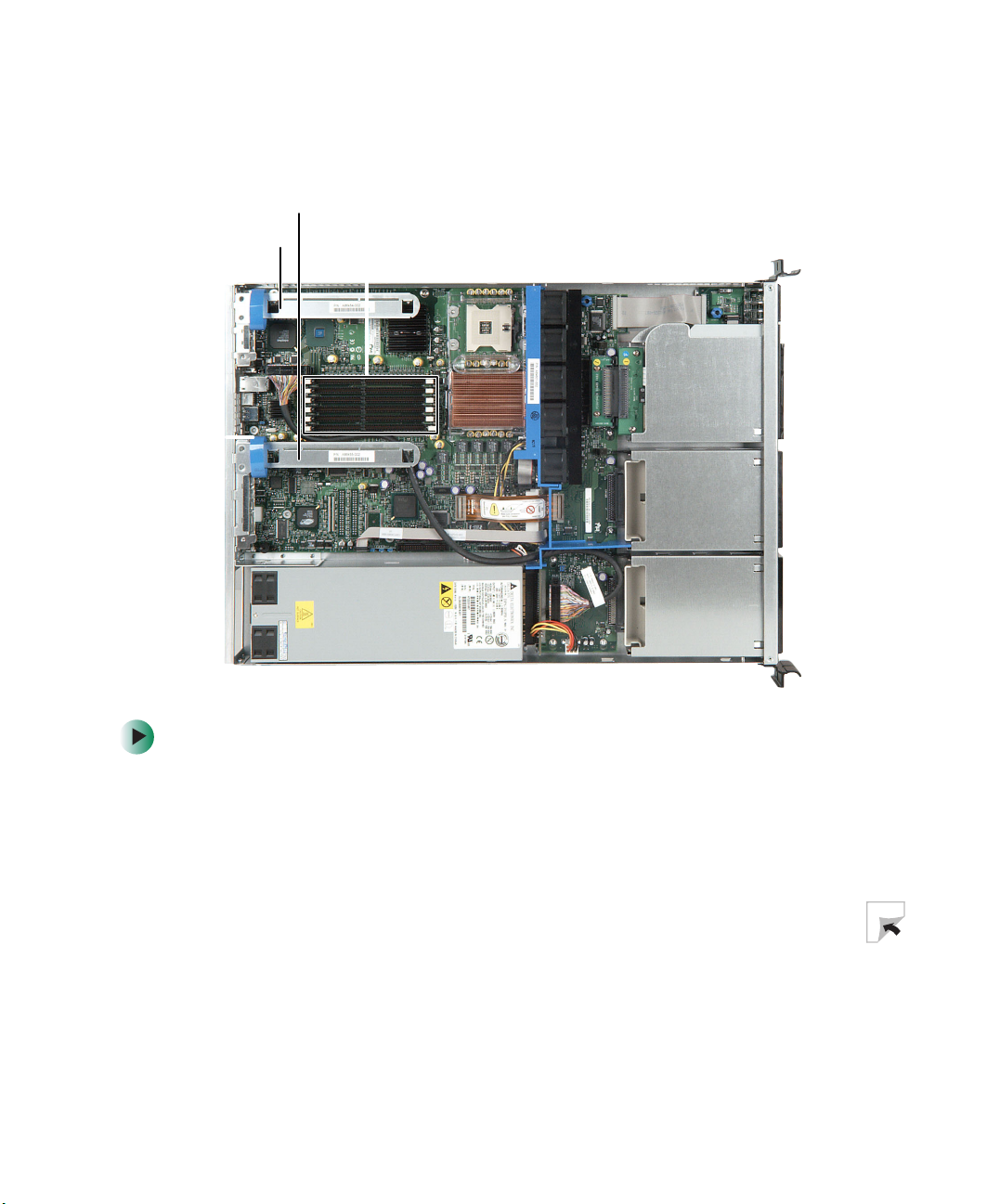
Installing PCI expansion cards
Full-height riser
card
Low-profile riser
card
To replace, add, or reseat a PCI expansion card:
1 Follow the instructions in “Preventing static electricity discharge” on
page 45.
2 Follow the instructions in “Opening the server case” on page 46.
3 If you are replacing a card, disconnect any cables that are attached to the
old card.
60
www.gateway.com
Installing PCI expansion cards
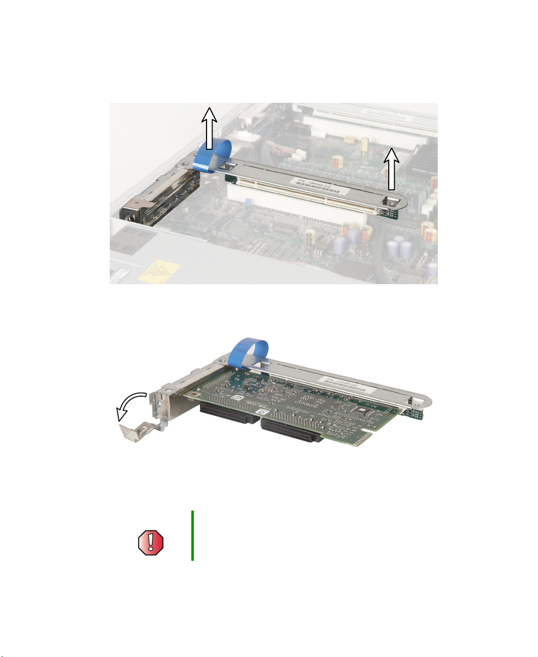
4 Locate the appropriate riser card, then lift the riser card from the system
board by lifting the blue plastic loop and the end of the riser card closest
to the front of the server.
5 Pull the card locking clip open, then swing the locking clip away from the
riser card.
6 If you are replacing a card, remove the old expansion card. You can slightly
seesaw the card end-to-end to loosen the card, but do not bend the card
sideways.
Warning Do not touch the contacts on the bottom part of the
expansion card. Touching the contacts can cause
electrostatic damage to the card.
www.gateway.com
61
Chapter 4: Installing Components
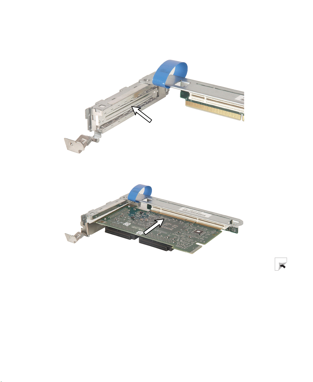
7 If this is the first time the slot will be used for an expansion card, remove
the slot’s EMI shield from the riser card by pushing it toward the back of
the riser card.
8 Insert the new card into the card slot. You can slightly seesaw the card
end-to-end to help insert the card, but do not bend the card sideways.
62
www.gateway.com
Installing PCI expansion cards
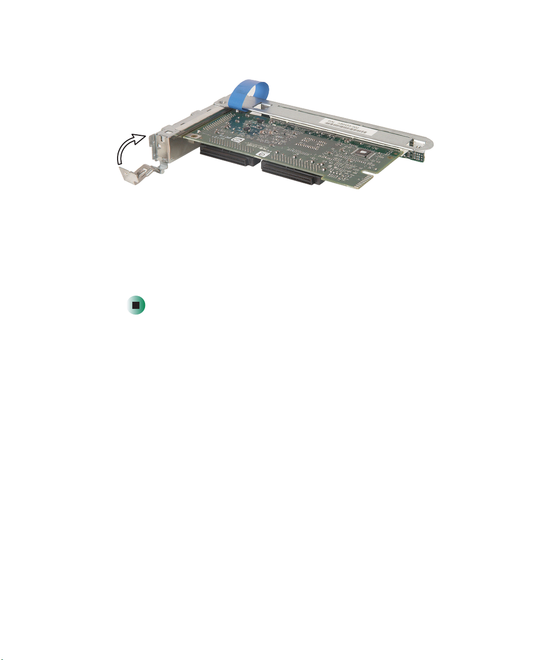
9 Rotate the card locking clip closed.
10 Connect any cables to the card following the instructions in the card’s
documentation.
11 Press the riser card back into the server.
12 Follow the instructions in “Closing the server case” on page 48.
13 See the card’s documentation for software installation instructions.
www.gateway.com
63
Chapter 4: Installing Components
Replacing the fan module
To replace the fan module:
1 Follow the instructions in “Preventing static electricity discharge” on
page 45.
2 Follow the instructions in “Opening the server case” on page 46.
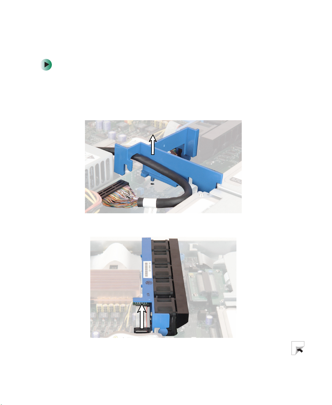
3 Lift the air baffle away from the server.
64
4 Unplug the fan module’s power cable from the system board.
www.gateway.com
Replacing the fan module
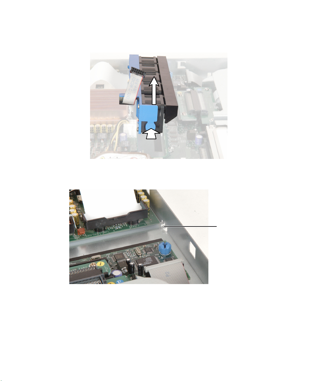
5 Press the module’s release button, then lift the module away from the
server.
6 Insert one end of the new fan module under the module guide located on
the right side of the case near the processors.
www.gateway.com
Fan module
guide
65
Chapter 4: Installing Components
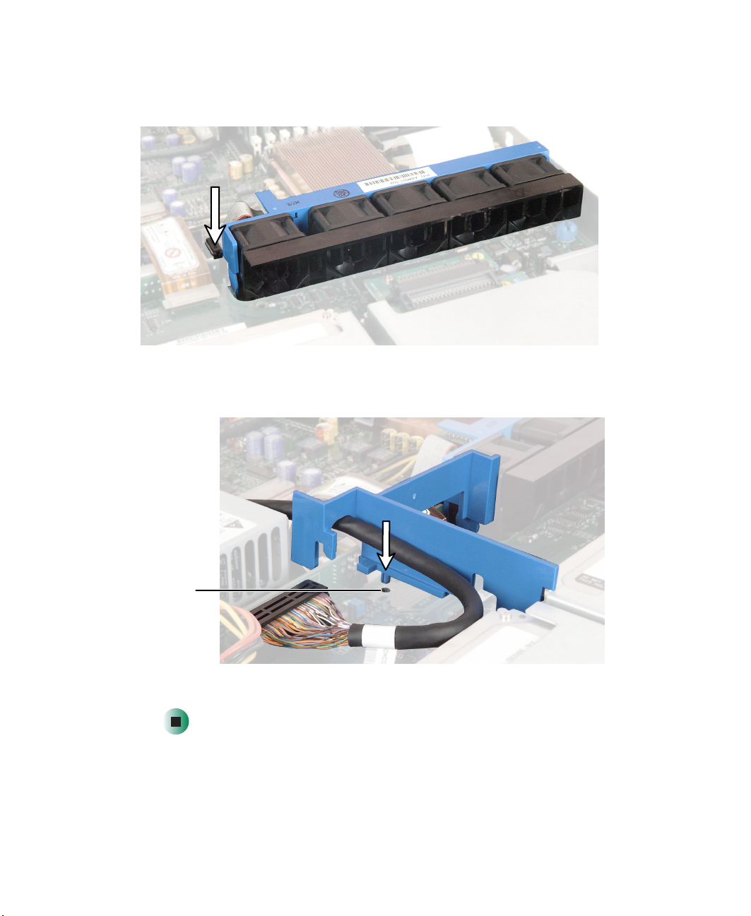
7 Press the module down until it clicks into place, then plug the fan module’s
power cable into the system board.
8 Insert the air baffle’s mounting post into the mounting post hole. Make
sure that the data cable is routed under the baffle.
66
Air baffle
mounting
post hole
9 Follow the instructions in “Closing the server case” on page 48.
www.gateway.com

Installing a processor
Installing a processor
The server is compatible with Intel® Xeon processors. The server automatically
detects the processors each time you turn on the server. Whenever you install
new processors, you should first install the most current version of the BIOS.
For instructions, see “Updating the BIOS” on page 91.
Important You must have a processor in the Processor 1 socket, or
your server will not start.
If you are upgrading your server from one processor to two,
you may need to reconfigure your operating system so it
can recognize the additional processor. For more
information, see your operating system’s documentation.
Warning A heat sink must be installed on the processor. Installing
a processor without a heat sink could damage the
processor.
Warning Processors and heat sinks may be hot if the computer has
been running. Before replacing a processor or heat sink,
allow them to cool for several minutes.
To replace a processor:
1 Install the most current BIOS version. For instructions, see “Updating the
BIOS” on page 91.
2 Follow the instructions in “Preventing static electricity discharge” on
page 45.
3 Follow the instructions in “Opening the server case” on page 46.
www.gateway.com
67

Chapter 4: Installing Components
4 Lift the transparent air duct away from the processor sockets.
5 Remove the fan module. For instructions, see “Replacing the fan module”
on page 64.
6 Press down on the heat sink locking clip’s lever to detach the clip on the
lever’s side, then slide the clip toward the opposite end and remove it from
the heat sink.
68
www.gateway.com
Installing a processor
7 Remove the remaining clip.
8 Remove the heat sink.
Important The heat sink mounting paste may harden over time and
hold the heat sink securely to the processor. If removing
the heat sink also pulls the processor out of the processor
socket, the processor should still be undamaged. Continue
with the procedure.
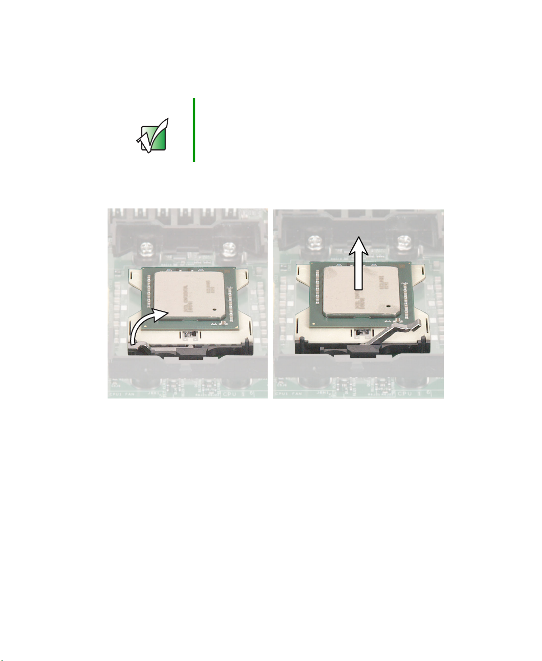
9 Rotate the processor release lever a full 135° to release the processor, then
lift the processor out of the socket.
www.gateway.com
69

Chapter 4: Installing Components
10 If you are installing a processor into an empty processor socket that has
an air dam installed, pinch the sides of the air dam together and lift it
away from the socket.
11 Before inserting the processor into the socket, make sure that:
■ The processor release lever is open all the way (135° from the closed
position)
■ The triangular arrow on the corner of the processor aligns with the
triangular icon on the corner of the processor socket
Important If you install two processors onto the system board, the
processors must be the same speeds, revision, core
voltage, and bus speed.
12 Install the new processor into the processor socket, then press the processor
locking lever down until it lays flat against the processor socket.
13 Apply thermal grease to the top of the processor, if necessary.
14 Place the heat sink on the processor, then press the heat sink locking clips
into place.
15 Follow the instructions in “Closing the server case” on page 48.
70
www.gateway.com

Replacing the power supply
Replacing the power supply
Warning The power supply in this server contains no
user-serviceable parts. Only a qualified computer
technician should service the power supply.
Your server comes with a 3-wire AC power cord fitted with
the correct plug style for your region. If this plug does not
match the connector on your surge protector, UPS, or wall
outlet, do not attempt to modify the plug in any way. Use
a surge protector, UPS, or wall outlet that is appropriate
for the supplied AC power cord.
To replace the power supply:
1 Follow the instructions in “Preventing static electricity discharge” on
page 45.
2 Follow the instructions in “Opening the server case” on page 46.
3 Lift the back of the power supply no more than ½ inch, just far enough
to clear the metal tabs that hold the power supply in place.
Metal tabs
www.gateway.com
71

Chapter 4: Installing Components
4 Slide the power supply toward the back of the server until the power supply
disconnects from the server.
72
www.gateway.com

Replacing the power supply
5 Lift the power supply out of the case.
6 Lay the new power supply onto the metal tabs, then slide it toward the
front of the server until the back of the power supply is secured behind
the metal tabs.
7 Follow the instructions in “Closing the server case” on page 48.
www.gateway.com
73
Chapter 4: Installing Components
Replacing the SCSI backplane
To replace the SCSI backplane:
1 Follow the instructions in “Preventing static electricity discharge” on
page 45.
2 Follow the instructions in “Opening the server case” on page 46.
3 Remove each of the drives from the server, including any drive in the Flex
Bay, and make note of which bay you remove each drive from. For
instructions, see “Replacing the CD/diskette drive in the Flex Bay” on
page 49 and “Installing a hard drive” on page 54.
4 Remove the fan module. For instructions, see “Replacing the fan module”
on page 64.
5 Remove the cables from the backplane board, then remove the
thumbscrew.
74
www.gateway.com
Replacing the SCSI backplane
6 Slide the backplane about 1/8 inch to the right, then lift it away from the
server.
7 Align the new backplane’s keyhole slots with the mounting posts on the
floor of the server case, then slide the backplane 1/8 inch to the left.
Keyhole slot
mounting post
8 Install the thumbscrew to secure the backplane to the server, then reattach
the cables you removed in Step 5.
www.gateway.com
75

Chapter 4: Installing Components
9 Install the drives back into the server. Make sure that you replace the drives
in the same bays you removed them from in Step 3.
10 Reinstall the fan module.
11 Follow the instructions in “Closing the server case” on page 48.
76
www.gateway.com

Replacing the CMOS battery
Replacing the CMOS battery
If the server clock does not keep time or the settings in the BIOS Setup utility
are not saved when you turn off the server, replace the CMOS battery with an
equivalent battery.
Warning Danger of explosion if battery is incorrectly replaced.
Replace only with the same or equivalent type
recommended by the manufacturer. Dispose of or recycle
used batteries by taking them to a hazardous waste facility.
Follow all local regulations for proper battery disposal.
To replace the battery:
1 Print the appendix for BIOS Settings in this guide.
2 Open the BIOS Setup utility. For instructions, see “Opening the BIOS Setup
utility” on page 90.
3 Record the BIOS settings on your printout, then close the utility.
4 Turn off your server, then follow the instructions in “Preventing static
electricity discharge” on page 45.
5 Follow the instructions in “Opening the server case” on page 46.
www.gateway.com
77
Chapter 4: Installing Components
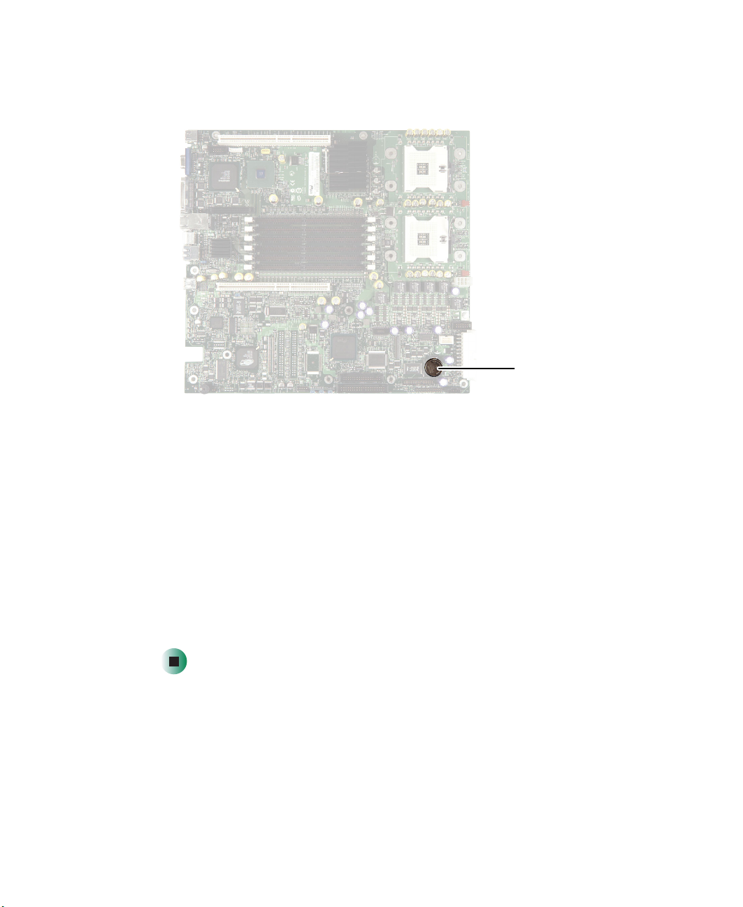
6 Locate the old battery on the system board and note its orientation. You
will need to install the new battery the same way.
7 Push the battery retention clip away from the battery until the battery lifts
up, then remove the old battery. You can use a screwdriver to help lift the
battery.
CMOS
battery
8 Make sure that the positive (+) side of the new battery is facing up, then
press the new battery into the socket until it snaps into place.
9 Follow the instructions in “Closing the server case” on page 48.
10 Turn on your server, then press F2 when the Gateway logo screen appears
during startup.
11 Restore any BIOS settings that you wrote down in Step 3.
12 Save all your settings and close the BIOS Setup utility.
78
www.gateway.com
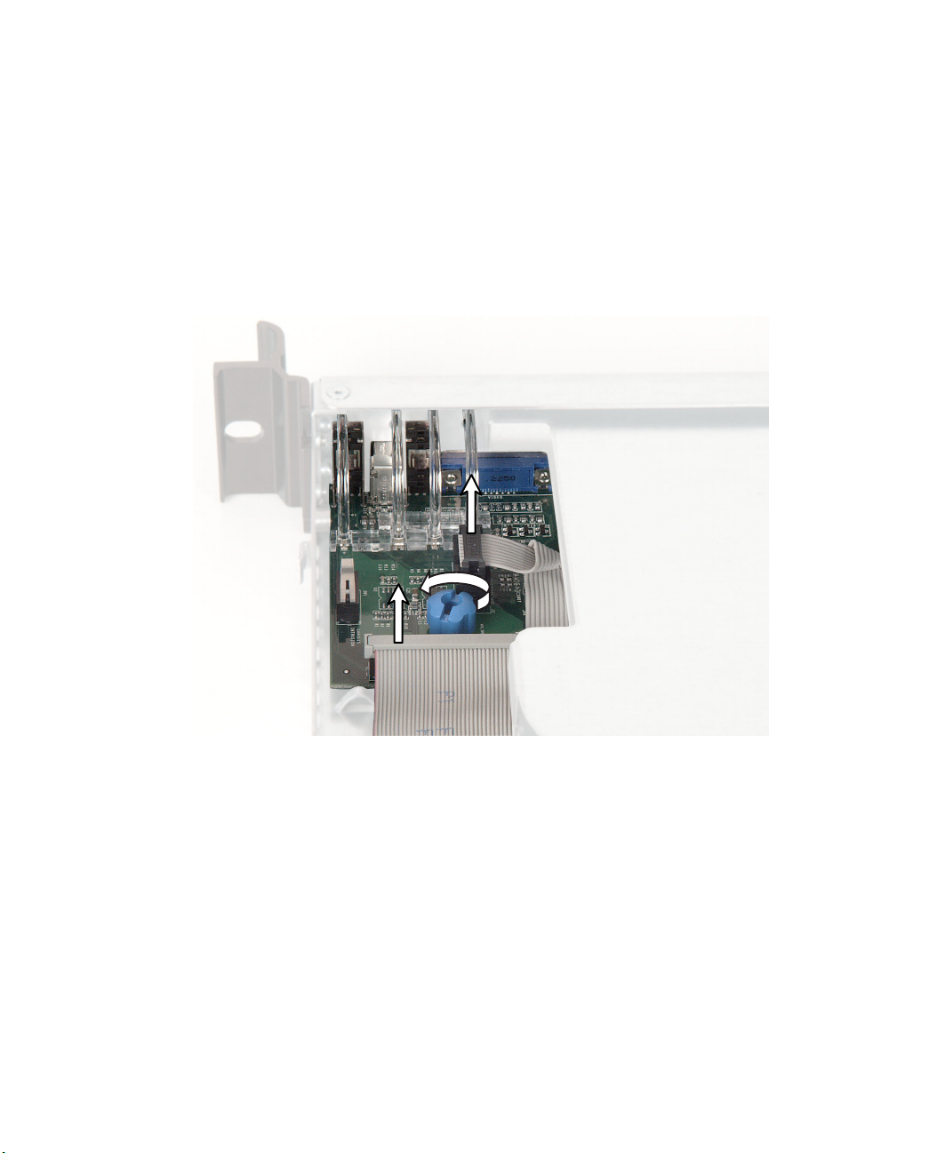
Replacing the power distribution board
Replacing the power distribution
board
1 Follow the instructions in “Preventing static electricity discharge” on
page 45.
2 Follow the instructions in “Opening the server case” on page 46.
3 Remove each of the drives from server, including any drive in the Flex Bay.
For instructions, see “Installing a hard drive” on page 54 and “Replacing
the CD/diskette drive in the Flex Bay” on page 49.
4 Remove the power supply. For instructions, see “Replacing the power
supply” on page 71.
5 Remove the air baffle and the fan module. For instructions, see “Replacing
the fan module” on page 64.
6 Remove the SCSI backplane. For instructions, see “Replacing the SCSI
backplane” on page 74.
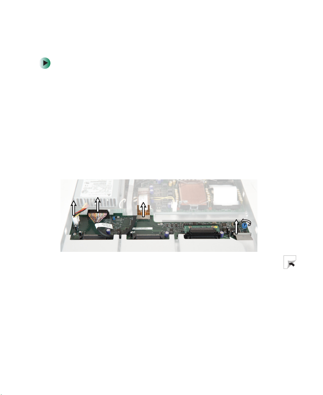
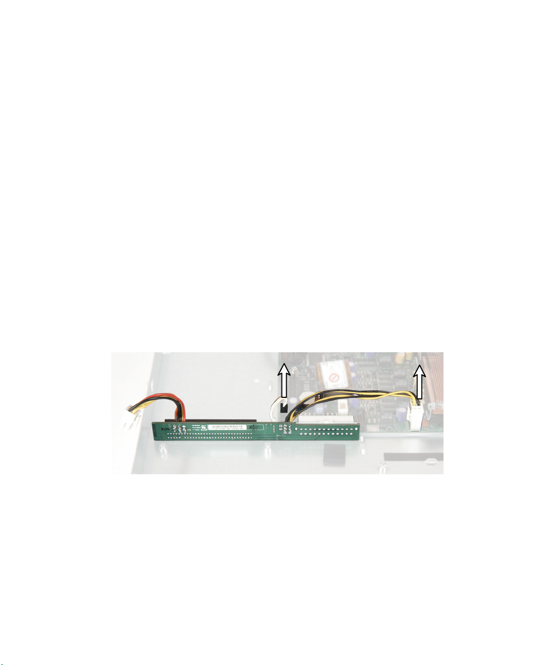
7 Unplug the two power distribution cables that connect to the system
board.
www.gateway.com
79
Chapter 4: Installing Components
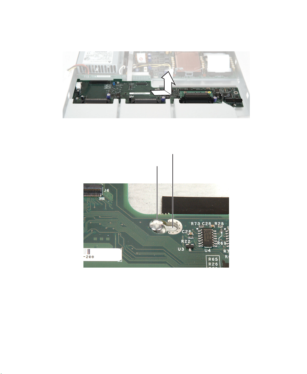
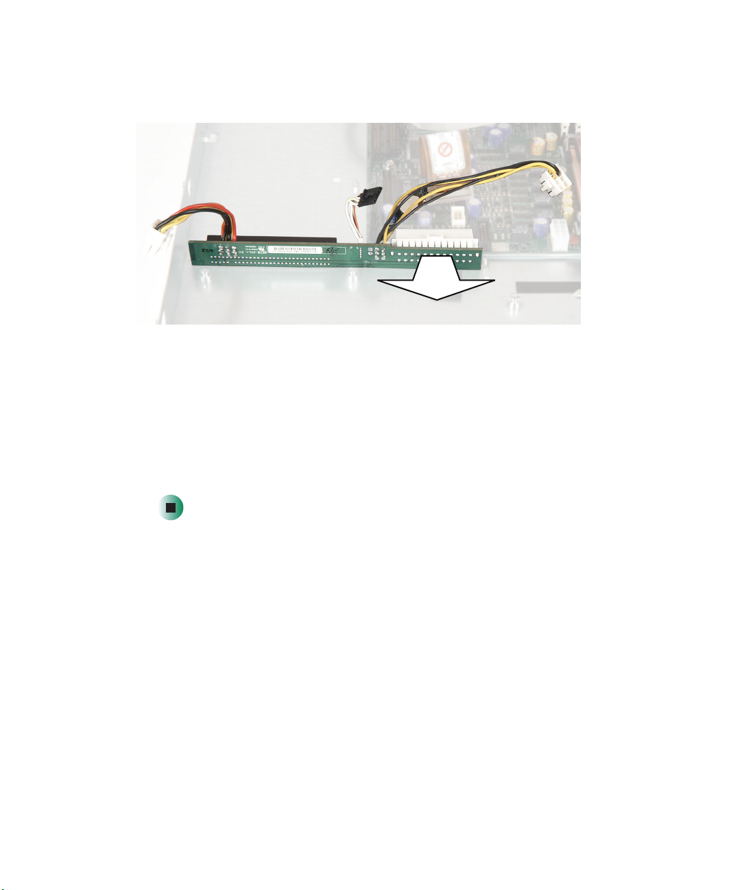
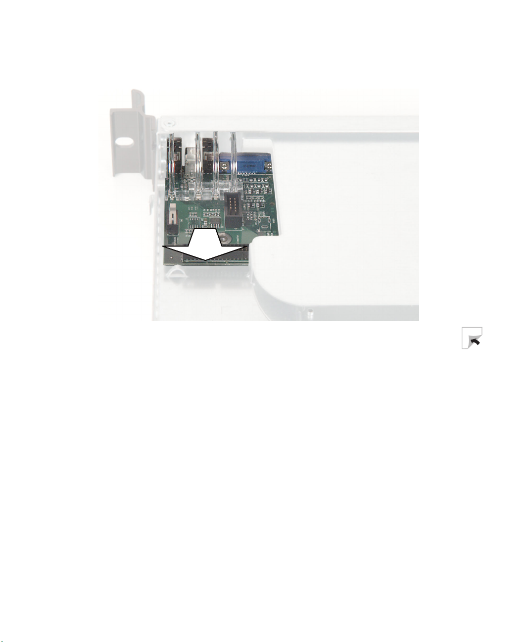
8 Pull the power distribution board toward the front of your server until it
disconnects from the system board.
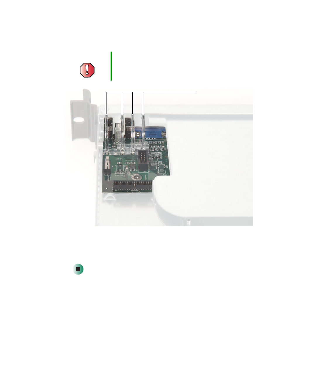
9 Plug the new power distribution board into the system board, then
reconnect the power distribution board cables.
10 Reinstall the SCSI backplane, then reinstall the power supply.
11 Reinstall the air baffle and fan module.
12 Reinstall the drives.
13 Follow the instructions in “Closing the server case” on page 48.
80
www.gateway.com
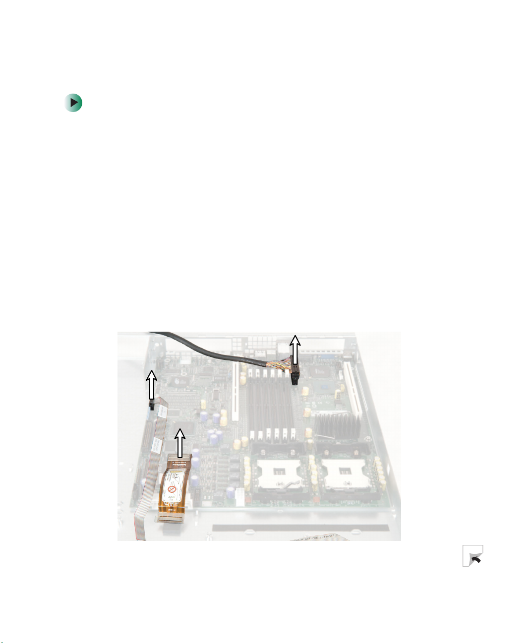
Replacing the front panel board
Replacing the front panel board
1 Follow the instructions in “Preventing static electricity discharge” on
page 45.
2 Follow the instructions in “Opening the server case” on page 46.
3 Remove the two cables from the front panel board, then remove the
thumbscrew.
www.gateway.com
81
Chapter 4: Installing Components
4 Lift the back of the board 1/8 inch, then pull it toward the back of your
server.
82
www.gateway.com
Replacing the front panel board
5 Insert the new front panel board so the light pipes align with their
corresponding holes in the front panel.
Warning Forcing the board into place without carefully guiding the
light pipes into their holes will damage the light pipes.
Light pipes
6 Install the thumbscrew to secure the board to the server, then reconnect
the cables.
7 Follow the instructions in “Closing the server case” on page 48.
www.gateway.com
83
Chapter 4: Installing Components
Replacing the system board
To replace the system board:
1 Follow the instructions in “Preventing static electricity discharge” on
page 45.
2 Follow the instructions in “Opening the server case” on page 46.
3 Remove the memory modules. For instructions, see “Installing memory”
on page 58.
4 Remove the riser cards. For instructions, see “Installing PCI expansion
cards” on page 60.
5 Remove the fan module. For instructions, see “Replacing the fan module”
on page 64.
6 Remove the heat sinks and processors. For instructions, see “Installing a
processor” on page 67.
7 Disconnect all cables from the system board, noting their locations and
orientation. (You will reconnect the cables after you install the new board.)
84
www.gateway.com
Replacing the system board
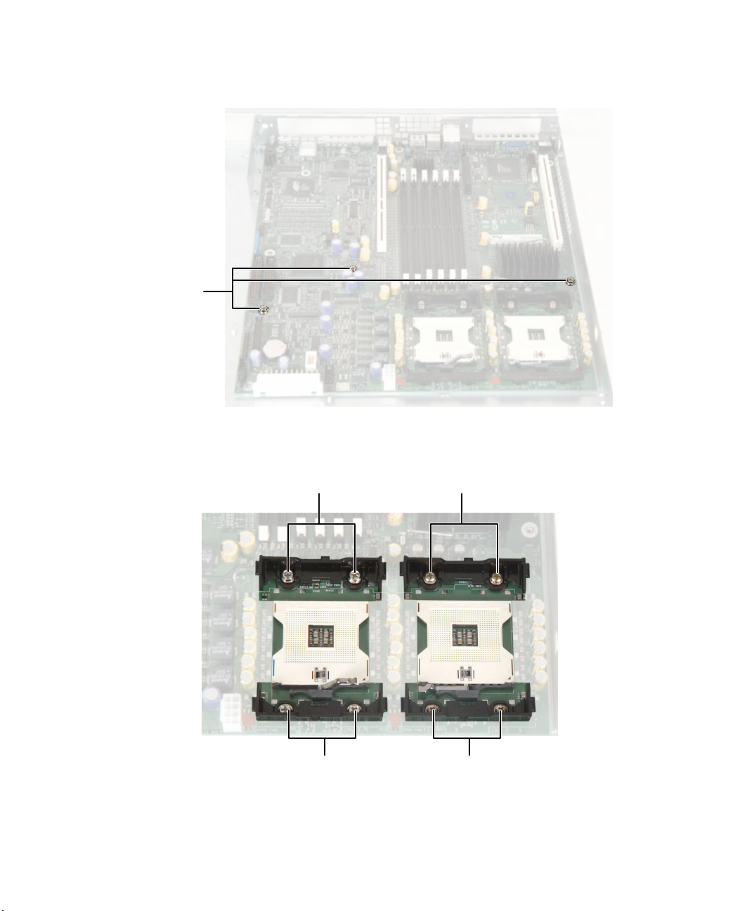
8 Remove the three screws that secure the system board to the server.
Screws
9 Remove the eight screws that secure the heat sink brackets to the system
board, then remove the brackets.
Screws Screws
Screws Screws
www.gateway.com
85

Chapter 4: Installing Components
10 Slide the system board toward the front of the server. If the board is difficult
to move, push on the rear I/O port panel for added leverage.
11 Lift the board away from the case.
12 Insert the new system board into the case, then slide the board toward the
back of the case so the board is held under the system board guides.
Guide
86
www.gateway.com

Replacing the system board
13 Replace the three system board screws you removed in Step 8.
14 Reinstall the heat sink brackets.
15 Reinstall the memory, processors, and fan module.
16 Reinstall the riser cards. For instructions, see “Installing PCI expansion
cards” on page 60.
17 Follow the instructions in “Closing the server case” on page 48.
18 Turn on your server, then press F2 when the Gateway logo screen appears
during startup.
19 Check BIOS settings to make sure that they detect the server’s new
hardware, then save your changes (if any) and close the BIOS Setup utility.
20 If your server does not start after installing the new system board, contact
Technical Support. For more information, see “Getting Help” on page 6.
www.gateway.com
87

Chapter 4: Installing Components
88
www.gateway.com

Using the BIOS
Setup Utility
Read this chapter to learn how to:
■ Open the BIOS Setup utility
■ Update the BIOS
■ Reset the BIOS settings to their factory defaults
■ Reset the BIOS passwords
5
89

Chapter 5: Using the BIOS Setup Utility
Opening the BIOS Setup utility
The BIOS Setup utility stores basic settings for your server. These settings include
basic hardware configuration, resource settings, and password security. These
settings are stored and saved even when the power is off.
Caution The options in the BIOS Setup utility have been set at the
factory for optimal performance. Changes to these
settings will affect the performance of your server.
Before changing any settings, write them down in case you
need to restore them later. You can record the settings on
a printout of this guide’s appendix for “BIOS Settings” on
page 119.
To open the BIOS Setup utility:
1 Restart your server, then press F2 when the Gateway logo screen appears
during startup.
When you select menu items, the Item Specific Help box on the right side
of the screen displays specific information about the selection. The
command bar across the bottom of the screen shows the keys you press
to access help, navigate through the menus, and perform other tasks.
90
2 Select one of these menus:
■ Main gives you access to basic information and settings related to your
server’s hardware and configuration.
■ Advanced gives you access to information and settings for PCI,
peripheral devices, memory, and the chipset.
■ Security gives you access to settings related to system access passwords.
For more information, see “Server security” on page 29.
■ Server gives you access to settings for system management, console
redirection, event log configuration, and fault-resilient boot settings.
■ Boot gives you access to information and settings for startup features
and startup sequences.
■ Exit gives you access to options for closing the BIOS Setup utility.
www.gateway.com

Updating the BIOS
If you need a new version of the BIOS, you can download the BIOS update from
Gateway, then install the new version from a diskette.
To update the BIOS:
1 Print the appendix for “BIOS Settings” on page 119.
2 Restart your server, then press F2 when the Gateway logo screen appears
during startup.
3 Record any custom BIOS settings on your printout.
4 Download the BIOS update from support.gateway.com.
5 Follow the instructions in the self-extracting BIOS update file.
6 Enter any custom BIOS settings you recorded in Step 3, then save your
changes and close the BIOS Setup utility.
Updating the BIOS
www.gateway.com
91

Chapter 5: Using the BIOS Setup Utility
Resetting the BIOS
You can use two methods to clear all BIOS Setup settings and return them to
the factory defaults:
■ Press the power and reset buttons on the front of the server.
■ Move the Clear BIOS jumper on the system board.
To reset the BIOS using the power and reset buttons:
1 Print the appendix for BIOS Settings in this guide.
2 Restart your server, then press F2 when the Gateway logo screen appears
during startup.
3 Record any custom BIOS settings on your printout.
4 Press the reset button and hold it down for four seconds or more, then
press the power button while continuing to hold down the reset button.
5 Release both buttons at the same time. The BIOS is reset.
To reset the BIOS using the system board jumper:
1 Print the appendix for BIOS Settings in this guide.
2 Restart your server, then press F2 when the Gateway logo screen appears
during startup.
3 Record any custom BIOS settings on your printout.
4 Follow the instructions in “Preventing static electricity discharge” on
page 45.
5 Turn off the server, then disconnect the power cord and all other cables
connected to the server.
6 Remove the top panel. For instructions, see “Opening the server case” on
page 46.
92
www.gateway.com
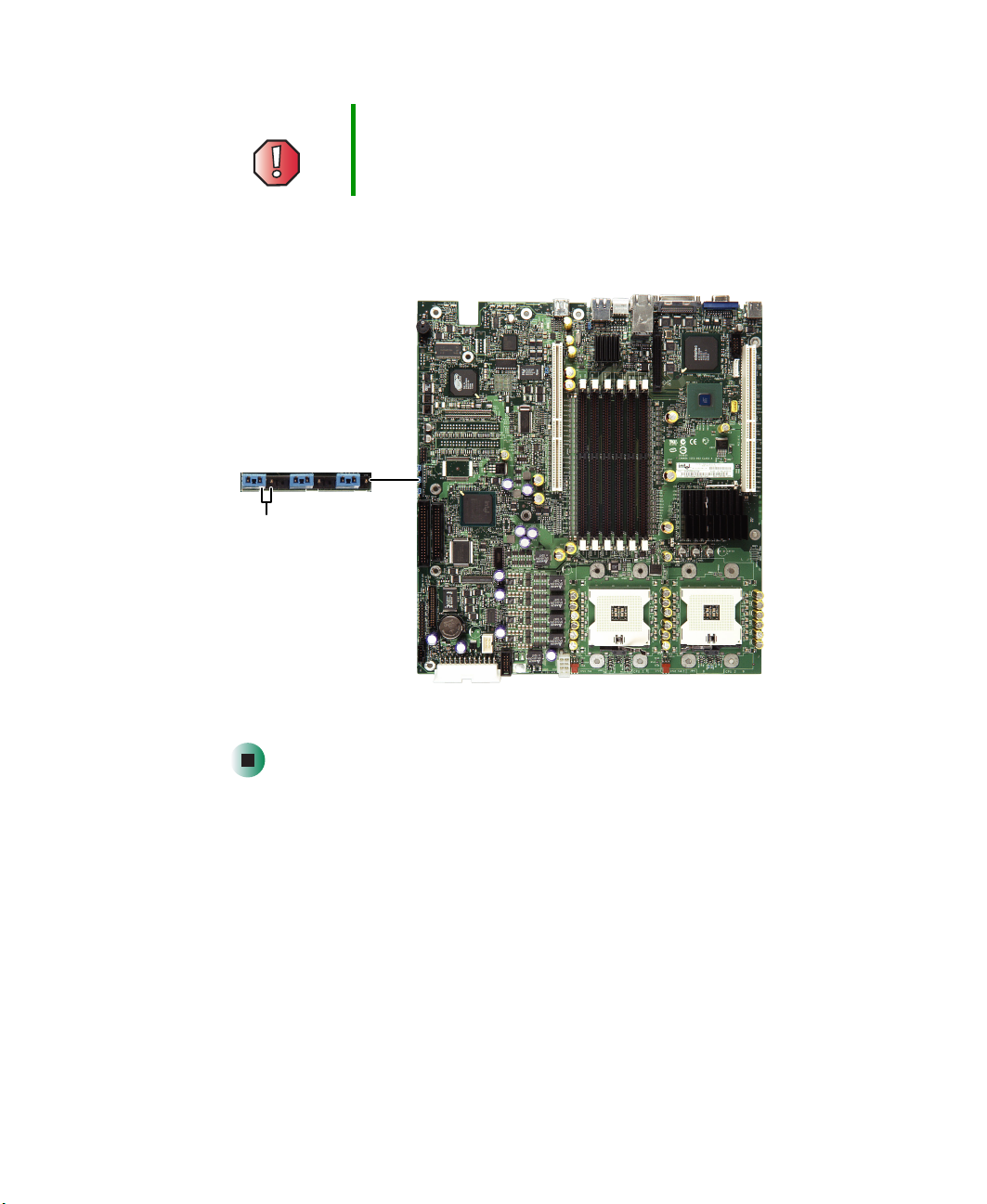
Resetting the BIOS
Warning Moving the jumper while the power is on can damage your
server. Always turn off the server and unplug the power
cord and all other cables before changing the jumper.
7 Place a jumper across the CLR/CMOS pins of jumper J1D4, then remove
the jumper. The BIOS settings are cleared.
CLR/CMOS
(clear BIOS) pins
8 Follow the instructions in “Closing the server case” on page 48.
Resetting BIOS passwords
To reset BIOS passwords, you must reset and clear all BIOS settings. To reset
BIOS passwords, follow the instructions in “Resetting the BIOS” on page 92.
www.gateway.com
93

Chapter 5: Using the BIOS Setup Utility
94
www.gateway.com
 Loading...