


Stylus Photo PX720WD
Epson Stylus Photo PX720WD, tylus Photo PX730WD, tylus Photo PX820FWD, tylus Photo PX830FWD, Artisan 725 Service Manual
...
SERVICE MANUAL
Color Inkjet Printer
Epson Artisan 810/
Epson Stylus Photo PX810FW/TX810FW/
Epson Artisan 835/
Epson Stylus Photo PX820FWD/TX820FWD/
Epson Artisan 837/
Epson Stylus Photo PX830FWD
Epson Artisan 710/
Epson Stylus Photo PX710W/TX710W/
Epson Artisan 725/
Epson Stylus Photo PX720WD/TX720WD
Epson Artisan 730/
Epson Stylus Photo PX730WD/TX730WD
Confidential
SEMF09-006

Notice:
All rights reserved. No part of this manual may be reproduced, stored in a retrieval system, or transmitted in any form or by any means, electronic, mechanical,
photocopying, recording, or otherwise, without the prior written permission of SEIKO EPSON CORPORATION.
The contents of this manual are subject to change without notice.
All effort have been made to ensure the accuracy of the contents of this manual. However, should any errors be detected, SEIKO EPSON would greatly appreciate being
informed of them.
The above not withstanding SEIKO EPSON CORPORATION can assume no responsibility for any errors in this manual or the consequences thereof.
EPSON is a registered trademark of SEIKO EPSON CORPORATION.
General Notice: Other product names used herein are for identification purpose only and may be trademarks or registered trademarks of their
respective owners. EPSON disclaims any and all rights in those marks.
Copyright © 2011 SEIKO EPSON CORPORATION.
I&I CS Quality Assurance Department
Confidential

PRECAUTIONS
Precautionary notations throughout the text are categorized relative to 1) Personal injury and 2) damage to equipment.
DANGER Signals a precaution which, if ignored, could result in serious or fatal personal injury. Great caution should be exercised in performing procedures preceded by
DANGER Headings.
WARNING Signals a precaution which, if ignored, could result in damage to equipment.
The precautionary measures itemized below should always be observed when performing repair/maintenance procedures.
DANGER
1. ALWAYS DISCONNECT THE PRODUCT FROM THE POWER SOURCE AND PERIPHERAL DEVICES PERFORMING ANY MAINTENANCE OR REPAIR
PROCEDURES.
2. NO WORK SHOULD BE PERFORMED ON THE UNIT BY PERSONS UNFAMILIAR WITH BASIC SAFETY MEASURES AS DICTATED FOR ALL ELECTRONICS
TECHNICIANS IN THEIR LINE OF WORK.
3. WHEN PERFORMING TESTING AS DICTATED WITHIN THIS MANUAL, DO NOT CONNECT THE UNIT TO A POWER SOURCE UNTIL INSTRUCTED TO DO
SO. WHEN THE POWER SUPPLY CABLE MUST BE CONNECTED, USE EXTREME CAUTION IN WORKING ON POWER SUPPLY AND OTHER ELECTRONIC
COMPONENTS.
4. WHEN DISASSEMBLING OR ASSEMBLING A PRODUCT, MAKE SURE TO WEAR GLOVES TO AVOID INJURIER FROM METAL PARTS WITH SHARP EDGES.
WARNING
1. REPAIRS ON EPSON PRODUCT SHOULD BE PERFORMED ONLY BY AN EPSON CERTIFIED REPAIR TECHNICIAN.
2. MAKE CERTAIN THAT THE SOURCE VOLTAGES IS THE SAME AS THE RATED VOLTAGE, LISTED ON THE SERIAL NUMBER/RATING PLATE. IF THE
EPSON PRODUCT HAS A PRIMARY AC RATING DIFFERENT FROM AVAILABLE POWER SOURCE, DO NOT CONNECT IT TO THE POWER SOURCE.
3. ALWAYS VERIFY THAT THE EPSON PRODUCT HAS BEEN DISCONNECTED FROM THE POWER SOURCE BEFORE REMOVING OR REPLACING PRINTED
CIRCUIT BOARDS AND/OR INDIVIDUAL CHIPS.
4. IN ORDER TO PROTECT SENSITIVE MICROPROCESSORS AND CIRCUITRY, USE STATIC DISCHARGE EQUIPMENT, SUCH AS ANTI-STATIC WRIST
STRAPS, WHEN ACCESSING INTERNAL COMPONENTS.
5. REPLACE MALFUNCTIONING COMPONENTS ONLY WITH THOSE COMPONENTS BY THE MANUFACTURE; INTRODUCTION OF SECOND-SOURCE ICs OR
OTHER NON-APPROVED COMPONENTS MAY DAMAGE THE PRODUCT AND VOID ANY APPLICABLE EPSON WARRANTY.
6. WHEN USING COMPRESSED AIR PRODUCTS; SUCH AS AIR DUSTER, FOR CLEANING DURING REPAIR AND MAINTENANCE, THE USE OF SUCH
PRODUCTS CONTAINING FLAMMABLE GAS IS PROHIBITED.
Confidential

About This Manual
A D J U S T M E N T
R E Q U I R E D
C A U T I O N
C H E C K
P O I N T
W A R N I N G
This manual describes basic functions, theory of electrical and mechanical operations, maintenance and repair procedures of the printer. The instructions and procedures included
herein are intended for the experienced repair technicians, and attention should be given to the precautions on the preceding page.
Manual Configuration
This manual consists of six chapters and Appendix.
CHAPTER 1.PRODUCT DESCRIPTIONS
Provides a general overview and specifications of the product.
CHAPTER 2.OPERATING PRINCIPLES
Describes the theory of electrical and mechanical operations of the
product.
CHAPTER 3.TROUBLESHOOTING
Describes the step-by-step procedures for the troubleshooting.
CHAPTER 4.DISASSEMBLY / ASSEMBLY
Describes the step-by-step procedures for disassembling and assembling
the product.
CHAPTER 5.ADJUSTMENT
Provides Epson-approved methods for adjustment.
CHAPTER 6.MAINTENANCE
Provides preventive maintenance procedures and the lists of Epsonapproved lubricants and adhesives required for servicing the product.
CHAPTER 7.Provides the following additional information for reference:
• Exploded Diagram
• Parts List
CHAPTER 8.Artisan 835/725/PX820FWD/TX820FWD/PX720WD/TX720WD
Provides particular information on the following models:
• Epson Artisan 835/Epson Stylus Photo PX820FWD/TX820FWD
• Epson Artisan 725/Epson Stylus Photo PX720WD/TX720WD
CHAPTER 9.Artisan 837/730/PX830FWD/PX730WD/TX730WD
Provides particular information on the following models:
• Epson Artisan 837/Epson Stylus Photo PX830FWD
• Epson Artisan 730/Epson Stylus Photo PX730WD/TX730WD
Symbols Used in this Manual
Various symbols are used throughout this manual either to provide additional
information on a specific topic or to warn of possible danger present during a
procedure or an action. Be aware of all symbols when they are used, and always read
NOTE, CAUTION, or WARNING messages.
Indicates an operating or maintenance procedure, practice or condition
that is necessary to keep the product’s quality.
Indicates an operating or maintenance procedure, practice, or condition
that, if not strictly observed, could result in damage to, or destruction of,
equipment.
May indicate an operating or maintenance procedure, practice or
condition that is necessary to accomplish a task efficiently. It may also
provide additional information that is related to a specific subject, or
comment on the results achieved through a previous action.
Indicates an operating or maintenance procedure, practice or condition
that, if not strictly observed, could result in injury or loss of life.
Indicates that a particular task must be carried out according to a certain
standard after disassembly and before re-assembly, otherwise the
quality of the components in question may be adversely affected.
Confidential

Revision Status
Revision Date of Issue Description
A July 29, 2009 First Release
B August 7, 2009 Revised Contents
Chapter 4
Caution of " Assembling the Printhead (p.135) " has been added.
Chapter 5
Made change in "5.1.1 Servicing Adjustment Item List (p.205) ".
Made change in "5.3.1 PG Adjustment/PG Inspection (p.229) ".
C January 7,2010 Revised Contents
Chapter 4
Made change in " Assembling the Printhead (p.135) ".
D June 18, 2010 Revised Contents
All chapters
Description about Epson Artisan 835/725/Epson Stylus Photo PX820FWD/TX820FWD/PX720WD/TX720WD has
been added.
Chapter 1
Checkpoint has been added in "1.1 Features (p.15) ".
Chapter 2
Checkpoint has been added in "2.1 Overview (p.49) ".
Made correction in "2.2 Power-On Sequence (p.53) ".
Chapter 3
Checkpoint has been added in "3.1 Overview (p.61) "
Note has been added in "3-5 Check point for Fatal error according to each phenomenon (Printer Mechanism)
(p.65) ".
Chapter 4
Checkpoint has been added in "4.1 Overview (p.101) "
Tool information for Epson Artisan 835/Epson Stylus Photo PX820FWD/TX820FWD has been added in "4.1.2
Tools (p.102) ".
Checkpoint has been added in "4.1.4 Additional Procedure/Procedural Differences (p.104) ".
Made change for checkpoint in "4.2 Disassembly Procedures (p.106) ".
Checkpoint has been added in "4.2.3.1 ADF Unit (p.110) ".
Checkpoint has been added in "4.2.3.5 Upper Housing (p.115) "
.
Confidential

Revision Date of Issue Description
D June 18, 2010
Chapter 4
Checkpoint has been added in "4.2.4.1 Panel Unit (p.124) ".
Made change for “adjustment required” and made correction in "4.2.4.2 Main Board / Grounding Plate M/B
Checkpoint has been added in "4.2.5.2 CR Scale (p.140) ".
Checkpoint has been added in "4.2.5.7 Ink System (p.147) ".
Made change for reassembly in "4.2.5.11 Waste Ink Tray Assy (p.156) " .
Made correction for reassembly in "4.2.7.2 ADF Cover Assy/ADF Cover L (p.168) ".
Reassembly has been added in "4.2.7.7 ADF Document Support Assy (p.173) ".
Made change for checkpoint in "4.3.1.3 Upper Housing (p.182) ".
Made change for checkpoint in "4.3.2.1 Panel Unit (p.188) ".
Made change
Chapter 5
Made change in "5.1 Adjustment Items and Overview (p.205) ".
Made change for caution in "5.2.6 MAC Address Setting (p.217) ".
Made change for caution and checkpoint, and made correction in "5.2.8 Case Open Sensor Check (p.220) ".
Made change for checkpoint in "5.2.9 AID inspection (p.223) ".
Made change for “Specified Scanner for BRS/PFP Adjustment” in "5.2.10 Banding Reduction System (BRS)
Adjustment / Paper Feed Amount Profile (PFP) Correction (p.224) ".
Made correction for checkpoint in "5.3.1.1 PG Adjustment (p.229) ".
Made correction for checkpoint in "5.3.1.2 PG Inspection (p.233) ".
Made change for checkpoint in "5.4.2 AID SHK Error Reset (p.239) ".
Chapter 6
Checkpoint has been added in "6.1 Overview (p.242) ".
Chapter 7
Checkpoint has been added in "7.1 Connector Summary (p.250) ".
Chapter 8
Information for Epson Artisan 835/725/Epson Stylus Photo PX820FWD/TX820FWD/PX720WD/TX720WD has
been added.
for
“adjustment required” in "4.3.2.2 Main Board/Grounding Plate M/B
(p.190) "
(p.126) "
.
.
E June 13, 2011 Revised Contents
All chapters
Description about Epson Artisan 837/730/Epson Stylus Photo PX830FWD/PX730WD/TX730WD has been added.
Chapter 1
Made change for checkpoint in "1.1 Features (p.15) ".
Chapter 2
Made change for checkpoint in "2.1 Overview (p.49) ".
Confidential

Revision Date of Issue Description
E June 13, 2011
Chapter 3
Made change for checkpoint in "3.1 Overview (p.61) "
Made change for and note has been changed in "3-4 Error Indications and Fault Occurrence Causes (p.63) ".
Note has been changed in "Table 3-5 Check point for Fatal error according to each phenomenon (Printer
Mechanism)" (p.65).
Made change for checkpoint in "3.7 FAX Troubleshooting (p.88) "
Description about Epson Artisan 837/730/Epson Stylus Photo PX830FWD/PX730WD/TX730WD has been added
in "3.8 Fax Function/External Connection Function Check (p.94) ".
Chapter 4
Made change for checkpoint in "4.1 Overview (p.101) "
Note has been changed in "Table 4-1 Tools" (p.102).
Note has been changed in "Table 4-2 Work Completion Check" (p.102).
Made change for checkpoint in "4.1.4 Additional Procedure/Procedural Differences (p.104) "
Made change for checkpoint in "4.2 Disassembly Procedures (p.106) "
Made change for checkpoint in "4.2.3.1 ADF Unit (p.110) ".
Made change for checkpoint and description in "4.2.3.2 Scanner Unit (p.111) ".
Made change in "4.2.3.3 Hinge (p.113) ".
Made change for checkpoint in "4.2.3.4 Upper Left Housing / Panel Lock Button (p.114) ".
Made change for checkpoint and description in "4.2.3.5 Upper Housing (p.115) ".
Made change for checkpoint and description in "4.2.3.6 Rear Left Housing (p.117) ".
Made change for checkpoint and description in "4.2.3.7 Left Housing / Decoration Belt L (p.117) ".
Made change in "4.2.3.8 Stacker Assy (p.118 ) ".
Made change for checkpoint and description in "4.2.3.10 Rear Right FAX Housing (p.120) ".
Made change for checkpoint and description in "4.2.3.11 Right Housing / Card Cover (p.121) " .
Checkpoint has been added in "4.2.3.12 Cassette Unit/EJ Cover Assy (p.122) ".
Made change for checkpoint in "4.2.4.1 Panel Unit (p.124) ".
Made change for checkpoint and description in "4.2.4.2 Main Board / Grounding Plate M/B (p.126) ".
Made change in "4.2.4.3 Power Supply Unit (p.130) ".
Made change in "4.2.4.4 Wireless LAN Board (p.131) ".
Made change for checkpoint and description in "4.2.4.5 Card Slot Assy (p.132) ".
Made change in "4.2.5.1 Printhead (p.133) ".
Made change for checkpoint and description in "4.2.5.2 CR Scale (p.140) ".
Made change in "4.2.5.3 PF Encoder (p.141) ".
Confidential

Revision Date of Issue Description
E June 13, 2011
Made change in "4.2.5.4 Decompression Pump Unit (p.142) ".
Made change for checkpoint and description in "4.2.5.5 CSIC Assy (p.143) ".
Made change in "4.2.5.6 Ink Supply IC Holder Assy (p.144) ".
Made change for checkpoint and description in "4.2.5.7 Ink System (p.147) ".
Made change in "4.2.5.8 Lower ASF Paper Guide Assy (p.149) ".
Made change in "4.2.5.9 CDR Tray Assy (p.153) ".
Made correction for reassembly in "4.2.5.11 Waste Ink Tray Assy (p.156) ".
Made change for checkpoint in "4.2.5.13 Front Paper Guide Waste Ink Pad (p.159) ".
Made change for checkpoint in "4.2.6.1 Scanner Upper Housing (p.160) ".
Made change in "4.2.6.2 Scanner Motor Unit (p.161) ".
Made change in "4.2.6.3 Scanner Carriage Unit (p.163) ".
Made change for description and reassembly in "4.2.6.4 Scanner CR Encoder Board (p.165) ".
Checkpoint has been added in "4.2.6.5 Cover Open Sensor (p.166) ".
Made change for checkpoint in "4.3.1.1 Scanner Unit (p.179) ".
Made change for checkpoint in "4.3.1.2 Upper Left Housing (p.181) ".
Made change for checkpoint in "4.3.1.3 Upper Housing (p.182) ".
Made change for checkpoint in "4.3.1.4 Rear Left Housing (p.184) ".
Made change for checkpoint in "4.3.1.5 Left Housing/Decoration Belt L (p.185) ".
Made change for checkpoint in "4.3.1.6 Rear Right Housing (p.186) ".
Made change for checkpoint in "4.3.1.7 Right Housing/Card Cover (p.187) "
Made change for checkpoint in "4.3.2.1 Panel Unit (p.188) ".
Made change for checkpoint and description in "4.3.2.2 Main Board/Grounding Plate M/B (p.190) ".
Made change for checkpoint in "4.3.2.3 Card Slot Assy (p.193) ".
Made change for checkpoint in "4.3.3 Disassembling the Scanner Unit (p.194) " .
Made change for checkpoint in "4.3.3.2 Scanner Upper Housing (p.194) ".
Checkpoint has been added and made change in "4.4 Routing FFC/cables (p.196) ".
Chapter 5
Made change for checkpoint and description in "5.1.1 Servicing Adjustment Item List (p.205) "
Checkpoint has been added and made change for caution in "5.2.8 Case Open Sensor Check (p.220) ".
Made change for checkpoint in "5.2.9 AID inspection (p.223) "
Made change in "5.2.10 Banding Reduction System (BRS) Adjustment / Paper Feed Amount Profile (PFP)
Correction (p.224) ".
Made change for checkpoint in "5.3 Adjustment without Using Adjustment Program (p.229) "
.
Confidential

Revision Date of Issue Description
E June 13, 2011
F September 12 , 2011 Revised contents
Made change in "5.3.4 Touch Panel Adjustment (Artisan 810/835/837/PX810FW/TX810FW/PX820FWD/
TX820FWD/PX830FWD only) (p.236) ".
Chapter 6
Made change for checkpoint in "6.1 Overview (p.242) ".
Made change in "6.1.3 Lubrication (p.243) " .
Chapter 7
Made change for checkpoint in "7.1 Connector Summary (p.250) ".
Chapter 8
Made change for checkpoint and description in "8.1 Overview (p.254) ".
Made change in "8.2 Operation principles (p .255) ".
Made change for checkpoint in "8.3.2.1 ADF Unit (p.264) ".
Made change for checkpoint and description in "8.3.2.4 CR Scale (p.270) ".
Made change for checkpoint and description in "8.3.2.5 Ink System (p.272) ".
Made change for checkpoint in "8.5.2 Service Maintenance (p.281) ".
Chapter 9
Information for Epson Artisan 837/730/Epson Stylus Photo PX830FWD/PX730WD/TX730WD has been added.
Chapter 4
Added Front Paper Guide Waste Ink Pad in Flow chart
Description for "4.2.5.13 Front Paper Guide Waste Ink Pad (p.159) " has been added.
Chapter 8
Added Front Paper Guide Waste Ink Pad in Flow chart
Chapter 9
Added Front Paper Guide Waste Ink Pad in Flow chart
G October 12,2011 Revised contents
Chapter 4
Description for "4.2.5.8.1 Reassemble of Lower ASF paper guide assy (p.151) "has been added.
Confidential

Epson Artisan 810/835/837/710/725/730/Epson Stylus Photo PX810FW/TX810FW/PX820FWD/TX820FWD/PX830FWD/PX710W/TX710W/PX720WD/TX720WD/PX730WD/TX730WD
Contents
Revision G
Chapter 1 PRODUCT DESCRIPTION
1.1 Features................................................................................................................ 15
1.2 Printing Specifications......................................................................................... 16
1.2.1 Basic Specifications.................................................................................... 16
1.2.2 Ink Cartridge............................................................................................... 16
1.2.3 Print Mode .................................................................................................. 17
1.2.4 Supported Paper.......................................................................................... 19
1.2.5 Printing Area............................................................................................... 22
1.3 Scanner Specifications......................................................................................... 22
1.3.1 Scanning Range .......................................................................................... 23
1.4 General Specifications......................................................................................... 23
1.4.1 Electrical Specifications ............................................................................. 23
1.4.2 Safety Approvals (Safety standards/EMI) .................................................. 24
1.4.3 Acoustic Noise............................................................................................ 24
1.4.4 Durability (TBD) ........................................................................................ 24
1.4.5 Environmental Conditions .......................................................................... 24
1.5 Interface............................................................................................................... 25
1.5.1 USB Interface ............................................................................................. 25
1.5.2 FAX Interface (Epson Artisan 810/Epson Stylus Photo PX810FW/TX810FW
only)............................................................................................................. 25
1.5.3 Network Interface ....................................................................................... 25
1.5.4 Memory Card Slots..................................................................................... 27
1.6 Control Panel ....................................................................................................... 28
1.6.1 Operation Buttons & LEDs ........................................................................ 28
1.6.2 Control Panel Functions in Each Mode...................................................... 29
1.6.2.1 Control Panel Functions ...................................................................... 29
1.7 Specification for Each Function .......................................................................... 31
1.7.1 Stand-alone Copy Function (Copy Mode).................................................. 31
1.7.1.1 Supported Paper and Copy Mode........................................................ 31
1.7.1.2 Stand-alone Copy Menu...................................................................... 32
1.7.1.3 Copy Speed (TBD).............................................................................. 32
1.7.1.4 Relation Between Original and Copy.................................................. 33
1.7.2 Memory Card Direct Print Function (Photos Mode) .................................. 33
1.7.2.1 Supported Paper and Print Mode......................................................... 33
1.7.2.2 Supported File Type and Media Type................................................. 34
1.7.2.3 Automatic Detection of Images in Memory Card ............................... 34
1.7.2.4 Specifications for Handling Image Data ............................................. 34
1.7.2.5 Memory Card Direct Print Menu ........................................................ 35
1.7.2.6 Makes Prints from Index Sheet Function............................................ 36
1.7.2.7 Print Layout......................................................................................... 37
1.7.3 Camera Direct Print Function (PictBridge)................................................ 40
1.7.3.1 Available DSC..................................................................................... 40
1.7.3.2 Print Settings Available from DSC ..................................................... 40
1.7.3.3 General Operation Procedure .............................................................. 41
1.7.3.4 Operations when a DSC is connected ................................................. 41
1.7.4 Various Settings (Setup Mode)................................................................... 42
1.7.5 FAX Function (FAX Mode) (Epson Artisan 810/Epson Stylus Photo
PX810FW/TX810FW only)........................................................................ 44
1.7.5.1 Basic Specifications ............................................................................ 44
1.7.5.2 Supported Functions............................................................................ 44
1.7.6 Other Functions .......................................................................................... 47
1.7.6.1 Scan Mode........................................................................................... 47
1.7.6.2 Backup Data ........................................................................................ 47
1.7.6.3 Print Ruled Papers............................................................................... 47
1.7.6.4 Coloring Book ..................................................................................... 47
Chapter 2 OPERATING PRINCIPLES
2.1 Overview ............................................................................................................. 49
2.1.1 Printer Mechanism...................................................................................... 49
2.1.2 Printhead..................................................................................................... 49
2.1.3 Motors & Sensors ....................................................................................... 50
2.1.4 PG setting ................................................................................................... 52
2.2 Power-On Sequence ............................................................................................ 53
2.2.1 Simple Reset Sequence............................................................................... 54
2.2.2 All Reset Sequence..................................................................................... 56
2.3 Printer Initialization............................................................................................. 59
Chapter 3 TROUBLESHOOTING
3.1 Overview ............................................................................................................. 61
3.1.1 Specified Tools ........................................................................................... 61
3.1.2 Preliminary Checks..................................................................................... 61
10
Confidential

Epson Artisan 810/835/837/710/725/730/Epson Stylus Photo PX810FW/TX810FW/PX820FWD/TX820FWD/PX830FWD/PX710W/TX710W/PX720WD/TX720WD/PX730WD/TX730WD
Revision G
3.2 Troubleshooting................................................................................................... 62
3.2.1 Motor and Sensor Troubleshooting ............................................................ 62
3.3 Troubleshooting by Error Message ..................................................................... 63
3.3.1 Error Message List...................................................................................... 63
3.3.2 Troubleshooting by Error Message ............................................................ 65
3.4 Troubleshooting without Error Message ............................................................. 77
3.4.1 Troubleshooting Printer Mechanism Problems .......................................... 77
3.4.2 Troubleshooting Electrical Problems ......................................................... 83
3.4.3 Troubleshooting I/F-related Problems........................................................ 83
3.5 Troubleshooting Duplex Unit Problems.............................................................. 85
3.6 Network Troubleshooting.................................................................................... 86
3.7 FAX Troubleshooting.......................................................................................... 88
3.7.1 FAX Log..................................................................................................... 88
3.7.2 Error Code/Superficial Phenomenon-Based Troubleshooting ................... 92
3.8 Fax Function/External Connection Function Check ........................................... 94
3.8.1 Outline ........................................................................................................ 94
3.8.2 Fax Function and External Connection Function Check............................ 94
3.8.2.1 Fax Function Check by [Method A] and External Connection Function
Check ................................................................................................... 94
3.8.2.2 Fax Function Check by [Method B] and External Connection Function
Check ................................................................................................... 98
3.8.2.3 Fax Function Check by [Method C] and External Connection Function
Check ................................................................................................... 99
Chapter 4 DISASSEMBLY/ASSEMBLY
4.1 Overview ........................................................................................................... 101
4.1.1 Precautions................................................................................................ 101
4.1.2 Tools ......................................................................................................... 102
4.1.3 Work Completion Check .......................................................................... 102
4.1.4 Additional Procedure/Procedural Differences .......................................... 104
4.2 Disassembly Procedures.................................................................................... 106
4.2.1 Parts transferred from the old printer when replacing the Printer Mechanism
108
4.2.2 Replacing the Head Supply Assy ............................................................. 109
4.2.3 Removing the Housing ............................................................................. 110
4.2.3.1 ADF Unit........................................................................................... 110
4.2.3.2 Scanner Unit ...................................................................................... 111
4.2.3.3 Hinge ................................................................................................. 113
4.2.3.4 Upper Left Housing / Panel Lock Button.......................................... 114
4.2.3.5 Upper Housing .................................................................................. 115
4.2.3.6 Rear Left Housing ............................................................................. 117
4.2.3.7 Left Housing / Decoration Belt L...................................................... 117
4.2.3.8 Stacker Assy...................................................................................... 118
4.2.3.9 Rear ASF Paper Guide Cover ........................................................... 119
4.2.3.10 Rear Right FAX Housing................................................................ 120
4.2.3.11 Right Housing / Card Cover............................................................ 121
4.2.3.12 Cassette Unit/EJ Cover Assy........................................................... 122
4.2.3.13 Paper Guide Top Assy..................................................................... 123
4.2.4 Removing the Circuit Board..................................................................... 124
4.2.4.1 Panel Unit.......................................................................................... 124
4.2.4.2 Main Board / Grounding Plate M/B.................................................. 126
4.2.4.3 Power Supply Unit ............................................................................ 130
4.2.4.4 Wireless LAN Board......................................................................... 131
4.2.4.5 Card Slot Assy................................................................................... 132
4.2.5 Disassembling the Printer Mechanism ..................................................... 133
4.2.5.1 Printhead............................................................................................ 133
4.2.5.2 CR Scale............................................................................................ 140
4.2.5.3 PF Encoder ........................................................................................ 141
4.2.5.4 Decompression Pump Unit................................................................ 142
4.2.5.5 CSIC Assy ......................................................................................... 143
4.2.5.6 Ink Supply IC Holder Assy ............................................................... 144
4.2.5.7 Ink System......................................................................................... 147
4.2.5.8 Lower ASF Paper Guide Assy .......................................................... 149
4.2.5.9 CDR Tray Assy ................................................................................. 153
4.2.5.10 Pick-up Roller ................................................................................. 155
4.2.5.11 Waste Ink Tray Assy ....................................................................... 156
4.2.5.12 Lower Paper Guide Waste Ink Pad Assy ........................................ 159
4.2.5.13 Front Paper Guide Waste Ink Pad................................................... 159
4.2.6 Disassembling Scanner Unit..................................................................... 160
4.2.6.1 Scanner Upper Housing .................................................................... 160
4.2.6.2 Scanner Motor Unit........................................................................... 161
4.2.6.3 Scanner Carriage Unit ....................................................................... 163
4.2.6.4 Scanner CR Encoder Board............................................................... 165
4.2.6.5 Cover Open Sensor............................................................................ 166
4.2.7 Disassembly of the ADF Unit .................................................................. 168
4.2.7.1 ADF Hinge ........................................................................................ 168
4.2.7.2 ADF Cover Assy/ADF Cover L........................................................ 168
4.2.7.3 ADF LD Frame Assy ........................................................................ 170
4.2.7.4 ADF Right Cover/ADF Rear Cover.................................................. 170
4.2.7.5 ADF Cover Stacker/ADF Document Support Cover........................ 172
4.2.7.6 ADF Front Cover .............................................................................. 173
4.2.7.7 ADF Document Support Assy........................................................... 173
11
Confidential

Epson Artisan 810/835/837/710/725/730/Epson Stylus Photo PX810FW/TX810FW/PX820FWD/TX820FWD/PX830FWD/PX710W/TX710W/PX720WD/TX720WD/PX730WD/TX730WD
Revision G
4.2.7.8 ADF Frame Unit................................................................................ 174
4.2.7.9 ADF Motor Unit................................................................................ 175
4.2.7.10 ADF PF Roller................................................................................. 178
4.3 Disassembly/reassembly procedures specific to Artisan 710/PX710W/TX710W ..
179
4.3.1 Removing the Housing ............................................................................. 179
4.3.1.1 Scanner Unit ...................................................................................... 179
4.3.1.2 Upper Left Housing........................................................................... 181
4.3.1.3 Upper Housing .................................................................................. 182
4.3.1.4 Rear Left Housing ............................................................................. 184
4.3.1.5 Left Housing/Decoration Belt L........................................................ 185
4.3.1.6 Rear Right Housing ........................................................................... 186
4.3.1.7 Right Housing/Card Cover................................................................ 187
4.3.2 Removing the Circuit Board..................................................................... 188
4.3.2.1 Panel Unit .......................................................................................... 188
4.3.2.2 Main Board/Grounding Plate M/B .................................................... 190
4.3.2.3 Card Slot Assy................................................................................... 193
4.3.3 Disassembling the Scanner Unit............................................................... 194
4.3.3.1 Document Cover................................................................................ 194
4.3.3.2 Scanner Upper Housing..................................................................... 194
4.4 Routing FFC/cables........................................................................................... 196
5.3 Adjustment without Using Adjustment Program .............................................. 229
5.3.1 PG Adjustment/PG Inspection.................................................................. 229
5.3.1.1 PG Adjustment .................................................................................. 229
5.3.1.2 PG Inspection .................................................................................... 233
5.3.2 CR Timing Belt Tension Inspection......................................................... 234
5.3.3 PF Timing Belt Tension Inspection.......................................................... 235
5.3.4 Touch Panel Adjustment (Artisan 810/835/837/PX810FW/TX810FW/
PX820FWD/TX820FWD/PX830FWD only) ........................................... 236
5.4 Other functions .................................................................................................. 238
5.4.1 I/S Decompress......................................................................................... 238
5.4.2 AID SHK Error Reset............................................................................... 239
Chapter 6 MAINTENANCE
6.1 Overview ........................................................................................................... 242
6.1.1 Cleaning.................................................................................................... 242
6.1.2 Service Maintenance................................................................................. 242
6.1.2.1 Printhead cleaning ............................................................................. 242
6.1.2.2 Service Call ....................................................................................... 243
6.1.3 Lubrication................................................................................................ 243
Chapter 7 APPENDIX
Chapter 5 ADJUSTMENT
5.1 Adjustment Items and Overview....................................................................... 205
5.1.1 Servicing Adjustment Item List................................................................ 205
5.1.2 Required Adjustments .............................................................................. 211
5.2 Adjustment Using Adjustment Program ........................................................... 213
5.2.1 Top Margin Adjustment ........................................................................... 213
5.2.2 Bi-D Adjustment....................................................................................... 213
5.2.3 PW Adjustment/First Dot Position Adjustment ....................................... 214
5.2.4 Head Angular Adjustment ........................................................................ 215
5.2.5 PF Adjustment .......................................................................................... 216
5.2.6 MAC Address Setting............................................................................... 217
5.2.7 PG Offset Value Adjustment .................................................................... 219
5.2.8 Case Open Sensor Check.......................................................................... 220
5.2.9 AID inspection.......................................................................................... 223
5.2.10 Banding Reduction System (BRS) Adjustment / Paper Feed Amount Profile
(PFP) Correction........................................................................................ 224
5.2.10.1 BRS (Banding Reduction System) Adjustment .............................. 226
5.2.10.2 PFP Adjustment............................................................................... 227
12
7.1 Connector Summary.......................................................................................... 250
7.2 Exploded Diagram / Parts List .......................................................................... 252
Chapter 8 Artisan 835/725/PX820FWD/TX820FWD/PX720WD/
TX720WD
8.1 Overview ........................................................................................................... 254
8.2 Operation principles .......................................................................................... 255
8.2.1 Power-On Sequence ................................................................................. 255
8.2.1.1 Simple Reset Sequence ..................................................................... 255
8.2.1.2 All Reset Sequence............................................................................ 257
8.3 Disassembly/assembly....................................................................................... 260
8.3.1 Procedural Differences between the Models............................................ 260
8.3.2 Disassembly Procedures ........................................................................... 262
8.3.2.1 ADF Unit........................................................................................... 264
8.3.2.2 Upper Housing .................................................................................. 266
8.3.2.3 Panel Unit.......................................................................................... 268
8.3.2.4 CR Scale............................................................................................ 270
8.3.2.5 Ink System......................................................................................... 272
Confidential

Epson Artisan 810/835/837/710/725/730/Epson Stylus Photo PX810FW/TX810FW/PX820FWD/TX820FWD/PX830FWD/PX710W/TX710W/PX720WD/TX720WD/PX730WD/TX730WD
Revision G
8.4 Adjustment ........................................................................................................ 274
8.4.1 Overview................................................................................................... 274
8.4.2 Required Adjustments (Artisan 835/725/PX820FWD/TX820FWD/
PX720WD/TX720WD)............................................................................. 275
8.4.3 Special Inspection Mode........................................................................... 278
8.4.4 Touch Panel Calibration ........................................................................... 279
8.4.5 Touch Panel Operation Check.................................................................. 279
8.5 Maintenance ...................................................................................................... 281
8.5.1 Cleaning.................................................................................................... 281
8.5.2 Service Maintenance................................................................................. 281
8.5.2.1 Printhead cleaning ............................................................................. 281
8.6 Connector Summary.......................................................................................... 282
Chapter 9 Artisan 837/730/PX830FWD/PX730WD/TX730WD
9.1 Overview ........................................................................................................... 284
9.2 Operation principles .......................................................................................... 285
9.2.1 Motors & Sensors ..................................................................................... 285
9.3 Troubleshooting................................................................................................. 287
9.4 Disassembly/assembly....................................................................................... 288
9.4.1 Procedural Differences between the Models ............................................ 288
9.4.2 Disassembly Procedures ........................................................................... 290
9.4.2.1 Decoration Plate Left Upper Sub ...................................................... 293
9.4.2.2 Upper Housing .................................................................................. 294
9.4.2.3 Decoration Plate Left Upper.............................................................. 296
9.4.2.4 Rear Left Housing ............................................................................. 297
9.4.2.5 Left Housing...................................................................................... 298
9.4.2.6 Rear Right FAX Housing .................................................................. 299
9.4.2.7 Right Housing/Housing Front Right ................................................. 300
9.4.2.8 Front Cover........................................................................................ 301
9.4.2.9 Housing Front Left ............................................................................ 301
9.4.2.10 Panel Unit ........................................................................................ 302
9.4.2.11 Relay Board..................................................................................... 304
9.4.2.12 Document Cover Open Sensor........................................................ 304
9.4.2.13 Scanner Open Sensor....................................................................... 306
9.4.2.14 Scanner Upper Housing................................................................... 307
9.4.2.15 Scanner Decoration Plate Front....................................................... 307
9.4.2.16 Decoration Plate Left Upper/Decoration Plate Left Upper Sub...... 308
9.4.2.17 Upper Housing ................................................................................ 309
9.4.2.18 Panel Unit ........................................................................................ 311
9.4.2.19 Rear Left Housing ........................................................................... 313
9.4.2.20 Rear Right Housing......................................................................... 314
9.4.2.21 Right Housing / Housing Front Right ............................................. 315
9.4.2.22 Scanner Open Sensor ...................................................................... 316
9.4.2.23 Scanner Upper Housing .................................................................. 317
9.4.2.24 Scanner Decoration Plate Front....................................................... 318
9.4.3 Routing FFC/cables .................................................................................. 319
9.5 Adjustment ........................................................................................................ 321
9.5.1 Overview .................................................................................................. 321
9.5.2 Required Adjustments (Artisan 837/730/PX830FWD/PX730WD/TX730WD)
321
9.5.3 Special Inspection Mode .......................................................................... 324
9.5.4 Tools Used for the Case Open Sensor Check........................................... 325
9.5.5 Scanners for Banding Reduction System (BRS) Adjustment / Paper Feed
Amount Profile (PFP) Correction.............................................................. 326
9.6 Connector Summary.......................................................................................... 327
13
Confidential

PRODUCT DESCRIPTION
CHAPTER
1
Confidential
Epson Artisan 810/835/837/710/725/730/Epson Stylus Photo PX810FW/TX810FW/PX820FWD/TX820FWD/PX830FWD/PX710W/TX710W/PX720WD/TX720WD/PX730WD/TX730WD
C H E C K
P O I N T
Revision G
1.1 Features
Description in this chapter is applied to Epson Artisan 810/710/
Epson Stylus Photo PX810FW/TX810FW/PX710W/TX710W.
For information on Epson Artisan 835/837/725/730/Epson Stylus
Photo PX820FWD/TX820FWD/PX830FWD/PX720WD/TX720WD/
PX730WD/TX730WD, see below.
Epson Artisan 835/725/Epson Stylus Photo PX820FWD/
TX820FWD/PX720WD/TX720WD:
Chapter 8 (p.253)
Epson Artisan 837/730/Epson Stylus Photo PX830FWD/
PX730WD/TX730WD:
Chapter 9 (p.283)
Epson Artisan 810/Epson Stylus Photo PX810FW/TX810FW/Epson Artisan 710/
Epson Stylus Photo PX710W/TX710W are color inkjet printers that have 4 in 1
functions (Printer for PC, Scanner for PC, Standalone copy, Memory card printing).
Common features
Printer
• Printing from a computer or directly printing from a memory card
• Auto duplex printing using Duplex Printing Unit (option for some destinations)
• Built-in CD/DVD tray
• Front double paper feeding function using a double-deck cassette
• Auto nozzle check (printhead cleaning) using AID
• Maximum print resolution: 5760 (H) x 1440 (V) dpi
• F6 Turbo II print head achieves higher print speed than ever
(Black: 180 nozzles x 1, Color: 180 nozzles x 5 per color)
• Six independent ink cartridges is installed (Dye inks)
• Borderless printing on specified EPSON brand paper is available
Scanner
• Scanning from a computer
• Offers a function that directly stores a scan data to a memory card
Copy
• High quality copy using the printing and scanning functions. Offers seven
preset copy layouts
USB interfaces
• Enables to print images in an external storage device
• Backup copy of a memory card can be made on an external media
• Offers camera direct print (PictBridge)
Network
• Available for printing, scanning, and memory card access via wired/wireless network
Bluetooth
• Mounting the optional Bluetooth unit offers wireless communication with
an external device
Features unique to Epson Artisan 810/Epson Stylus Photo PX810FW/
TX810FW
FAX
• Sending/receiving fax
ADF
• Continuous scanning using an ADF
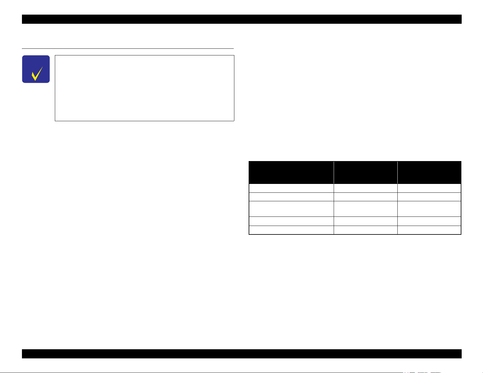
Differences between the models
Epson Artisan 810/Epson Stylus Photo PX810FW/TX810FW/Epson Artisan 710/
Epson Stylus Photo PX710W/TX710W are different on ADF, FAX and the Panel
specifications as shown below.
Epson Artisan 810/Epson
Item
LCD display size 3.5 inch 2.5 inch
Panel operation Touch panel Button
Scanner resolution
(Main scan x Sub scan)
ADF Equipped ---
FAX function Supported ---
Note* : When scanning using ADF
Stylus Photo PX810FW/
TX810FW
4,800 dpi x 4,800 dpi
(1,200 dpi x 600 dpi)
Epson Artisan 710/Epson
Stylus Photo PX710W/
TX710W
2,400 dpi x 4,800 dpi
*
Dimensions
Epson Artisan 810/Epson Stylus Photo PX810FW/TX810FW
• Dimensions*1: 466 mm (W) x 385 mm (D) x 198 mm (H)
• Weight*2: 10.5 kg
Epson Artisan 710/Epson Stylus Photo PX710W/TX710W
• Dimensions*1: 466 mm (W) x 385 mm (D) x 150 mm (H)
• Weight*2: 9.0 kg
Note *1: Paper support and stacker are closed. Rubber feet are included.
*2 : Except ink cartridges and cables such as the AC cable, etc.
PRODUCT DESCRIPTION Features 15
Confidential
Epson Artisan 810/835/837/710/725/730/Epson Stylus Photo PX810FW/TX810FW/PX820FWD/TX820FWD/PX830FWD/PX710W/TX710W/PX720WD/TX720WD/PX730WD/TX730WD
C A U T I O N
Revision G
1.2 Printing Specifications
1.2.1 Basic Specifications
Table 1-1. Printer Specifications
Item Specification
Print method On-demand ink jet
Black: 180 nozzles x 1
Nozzle configuration
Print direction Bi-directional minimum distance printing, Unidirectional printing
Print resolution
Control code
Input buffer size 64 Kbytes
Paper feed method Friction feed, using the ASF (Auto Sheet Feeder)
Paper path Front feed, front out
Paper feed rates 86 msec. (at 25.4 mm feed)
PF interval Programmable in 0.01764 mm (1/1440 inch) steps
Color: 180 nozzles x 5
(Light Cyan, Magenta, Yellow, Cyan, Light Magenta)
Horizontal x Vertical (dpi)
• 360 x 180 • 720 x 720
• 360 x 360 • 5760 x 1440
• 720 x 360
• ESC/P Raster command
• ESC/P-R (RGB) command
• EPSON Remote command
1.2.2 Ink Cartridge
The product numbers of the EPSON ink cartridges for this printer are shown below.
Table 1-2. Product No. of Ink Cartridges
Color EAI CISMEA/Asia Euro
Black T0981 (S)
Cyan
Magenta
Yellow
Light Cyan
Light Magenta
T0982 (S)
T0992 (2S)
T0983 (S)
T0993 (2S)
T0984 (S)
T0994 (2S)
T0985 (S)
T0995 (2S)
T0986 (S)
T0996 (2S)
T0811N (S)
T0821N (2S)
T0812N (S)
T0822N (2S)
T0813N (S)
T0823N (2S)
T0814N (S)
T0824N (2S)
T0815N (S)
T0825N (2S)
T0816N (S)
T0826N (2S)
Shelf life
Two years from production date (if unopened), six months after opening package.
Storage Temperature
Table 1-3. Storage Temperature
Situation Storage Temperature Limit
When stored in individual boxes
When installed in main unit
-20 oC to 40 oC
(-4oF to 104oF)
-20 oC to 40 oC
(-4oF to 104oF)
1 month max. at 40 oC (104oF)
T0791 (S)
T0801 (2S)
T0792 (S)
T0802 (2S)
T0793 (S)
T0803 (2S)
T0794 (S)
T0804 (2S)
T0795 (S)
T0805 (2S)
T0796 (S)
T0806 (2S)
Dimension
12.7 mm (W) x 68 mm (D) x 47 mm (H)
Do not use expired ink cartridges.
The ink in the ink cartridge freezes at -16 °C (3.2 oF). It takes
about three hours under 25 °C (77
o
F) until the ink thaws and
becomes usable.
PRODUCT DESCRIPTION Printing Specifications 16
Confidential
Epson Artisan 810/835/837/710/725/730/Epson Stylus Photo PX810FW/TX810FW/PX820FWD/TX820FWD/PX830FWD/PX710W/TX710W/PX720WD/TX720WD/PX730WD/TX730WD
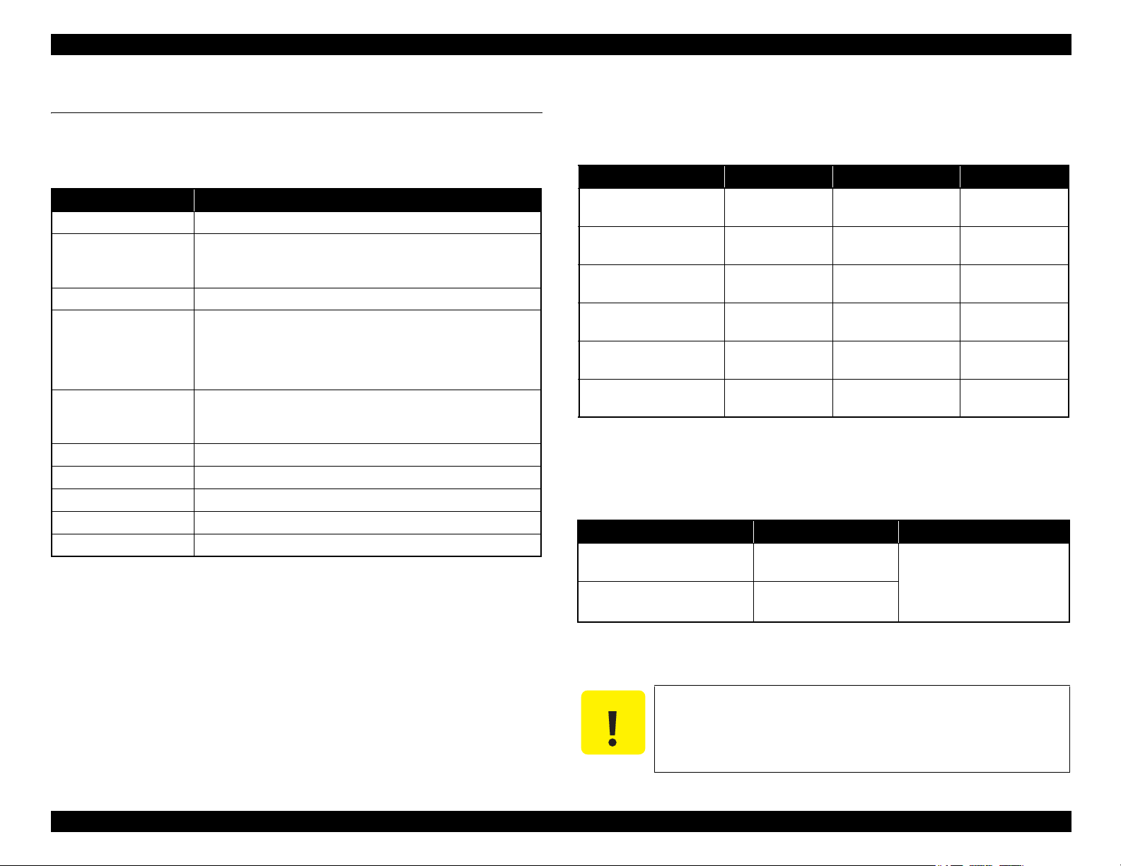
1.2.3 Print Mode
Revision G
Media Print Mode
• Plain paper
• Premium Bright
White Paper (EAI)
• Premium Bright
White Inkjet Paper
(others)
• Ultra Premium Photo
Paper Glossy (EAI)
• Ultra Glossy Photo
Paper (others)
• Photo Paper Glossy
(EAI)
• Glossy Photo Paper
(others)
• Premium Photo Paper
Glossy (EAI)
• Premium Glossy
Photo Paper (others)
• Premium Photo Paper
Semi-Gloss (EAI)
• Premium Semigloss
Photo Paper (other)
• Ultra Premium Photo
Paper Luster (EAI)
• Photo Paper
• Premium Presentation
Paper Matte (EAI)
• Matte Paper Heavyweight (others)
• Presentation Paper
Matte (EAI)
• Photo Quality Inkjet
*2
(others)
Paper
Table 1-4. Print Mode (Color)
Resolution
(H x V) dpi
Draft 360x180
Normal 360x360
Photo Fine 720x720
Photo
Photo
*2
*2
720x720
(1.0 pass)
720x720
(2.0 pass)
Super Photo 5760x1440
Fine 720x360
Photo
Photo
*2
*2
720x720
(1.0 pass)
720x720
(2.0 pass)
Super Photo 5760x1440
Photo
*2
720x720
(2.0 pass)
Super Photo 5760x1440
Photo
*2
720x720
(2.0 pass)
Dot Size
(cps*1)
(450cps)
MC2-1
(360cps)
MC1-1
(240cps)
MC1-2
(240cps)
MC2-2
(280cps)
MC1-5
(200cps)
MC1-2
(240cps)
MC1-2
(240cps)
MC2-2
(280cps)
MC1-5
(200cps)
MC2-2
(280cps)
MC1-5
(200cps)
MC2-2
(280cps)
Eco
Micro
Bi-d
Weave
Border-
less
ON OFF N/A
ON OFF N/A
ON ON N/A
ON ON OK
ON ON OK
ON ON OK
ON ON OK
ON ON OK
ON ON OK
ON ON OK
ON ON OK
ON ON OK
ON ON N/A
Table 1-4. Print Mode (Color)
Media Print Mode
Resolution
(H x V) dpi
Normal 360x360
Envelope
Photo Fine 720x720
• Premium Presentation
Paper Matte Doublesided (EAI)
• Double-sided Matte
Photo
*2
720x720
(2.0 pass)
Paper (Euro, Asia)
Photo stickers Photo
*2
720x720
(2.0 pass)
• Iron-On Transfer
Paper (EAI)
• Iron-On Cool Peal
Photo Fine 720x720
Transfer Paper
(others)
CD/DVD Label
High-quality CD/DVD
*3
Label
*3
Super Photo 5760x1440
Super Photo 5760x1440
Note *1: cps = character per second
*2 : Photo mode uses 1.0 pass or 2.0 pass depending on the paper size.
1.0 pass supported size: 4” x 6”
2.0 pass supported size: 5” x 7”, 8” x 10”, Letter, A4, 16:9 wide
*3 : Print quality is not guaranteed in the settings other than [type: “CDR Tray” & media:
“CD/DVD”] when carrying out CD/DVD printing from the PC.
Dot Size
(cps*1)
MC2-1
(360cps)
MC1-1
(240cps)
MC2-2
(280cps)
MC2-2
(280cps)
MC1-1
(240cps)
MC1-5
(200cps)
MC1-5
(200cps)
Micro
Bi-d
Weave
OFF OFF N/A
OFF ON N/A
ON ON N/A
ON ON N/A
OFF ON N/A
ON ON N/A
ON ON N/A
Border-
less
PRODUCT DESCRIPTION Printing Specifications 17
Confidential

Epson Artisan 810/835/837/710/725/730/Epson Stylus Photo PX810FW/TX810FW/PX820FWD/TX820FWD/PX830FWD/PX710W/TX710W/PX720WD/TX720WD/PX730WD/TX730WD
Revision G
Media Print Mode
• Plain paper
• Premium Bright
White Paper (EAI)
• Premium Bright
White Inkjet Paper
(others)
• Ultra Premium Photo
Paper Glossy (EAI)
• Ultra Glossy Photo
Paper (others)
• Photo Paper Glossy
(EAI)
• Glossy Photo Paper
(others)
• Premium Photo Paper
Glossy (EAI)
• Premium Glossy
Photo Paper (others)
• Premium Photo Paper
Semi-Gloss (EAI)
• Premium Semigloss
Photo Paper (other)
• Ultra Premium Photo
Paper Luster (EAI)
• Photo Paper
• Premium Presentation
Paper Matte (EAI)
• Matte Paper Heavyweight (others)
• Presentation Paper
Matte (EAI)
• Photo Quality Inkjet
Paper*2 (others)
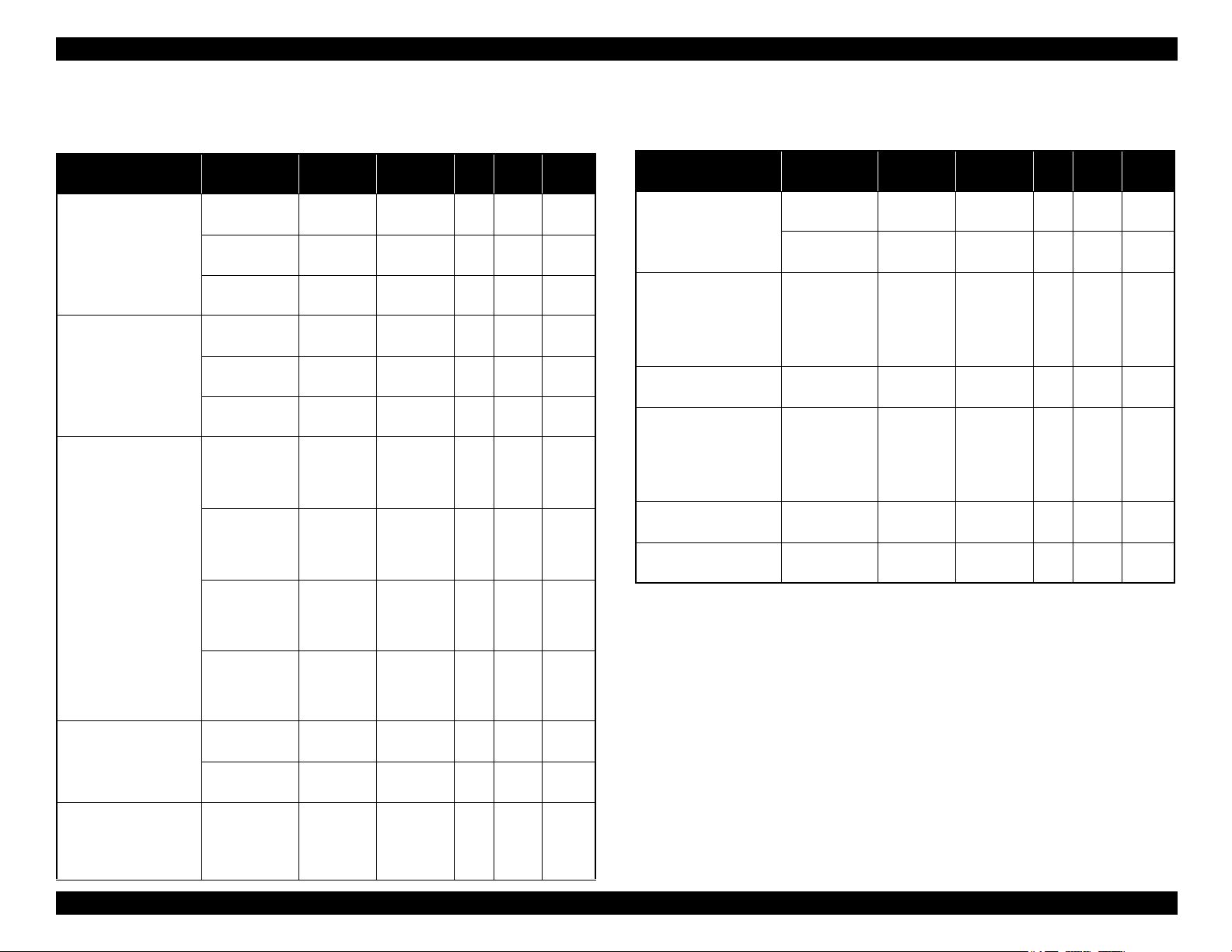
Table 1-5. Print Mode (Monochrome)
Resolution
(H x V) dpi
Draft 360x180
Normal 360x360
Photo Fine 720x720
Photo
Photo
*2
*2
720x720
(1.0 pass)
720x720
(2.0 pass)
Super Photo 5760x1440
Fine 720x360
Photo
Photo
*2
*2
720x720
(1.0 pass)
720x720
(2.0 pass)
Super Photo 5760x1440
Photo
*2
720x720
(2.0 pass)
Super Photo 5760x1440
Photo
*2
720x720
(2.0 pass)
Dot Size
(cps*1)
Eco
(450cps)
MC2-1
(360cps)
MC1-1
(240cps)
MC1-2
(240cps)
MC2-2
(280cps)
MC1-5
(200cps)
MC1-2
(240cps)
MC1-2
(240cps)
MC2-2
(280cps)
MC1-5
(200cps)
MC2-2
(280cps)
MC1-5
(200cps)
MC2-2
(280cps)
Micro
Bi-d
Weave
Border-
less
ON OFF N/A
ON OFF N/A
ON ON N/A
ON ON OK
ON ON OK
ON ON OK
ON ON OK
ON ON OK
ON ON OK
ON ON OK
ON ON OK
ON ON OK
ON ON N/A
Table 1-5. Print Mode (Monochrome)
Media Print Mode
Resolution
(H x V) dpi
Normal 360x360
Envelope
Photo Fine 720x720
• Premium Presentation
Paper Matte Doublesided (EAI)
• Double-sided Matte
Photo
*2
720x720
(2.0 pass)
Paper (Euro, Asia)
Photo stickers Photo
*2
720x720
(2.0 pass)
• Iron-On Transfer
Paper (EAI)
• Iron-On Cool Peal
Photo Fine 720x720
Transfer Paper
(others)
CD/DVD Label
High-quality CD/DVD
*3
Label
*3
Super Photo 5760x1440
Super Photo 5760x1440
Note *1: cps = character per second
*2 : Photo mode uses 1.0 pass or 2.0 pass depending on the paper size.
1.0 pass supported size: 4” x 6”
2.0 pass supported size: 5” x 7”, 8” x 10”, Letter, A4, 16:9 wide
*3 : Print quality is not guaranteed in the settings other than [type: “CDR Tray” & media:
“CD/DVD”] when carrying out CD/DVD printing from the PC.
Dot Size
(cps*1)
MC2-1
(360cps)
MC1-1
(240cps)
MC2-2
(280cps)
MC2-2
(280cps)
MC1-1
(240cps)
MC1-5
(200cps)
MC1-5
(200cps)
Micro
Bi-d
Weave
OFF OFF N/A
OFF ON N/A
ON ON N/A
ON ON N/A
OFF ON N/A
ON ON N/A
ON ON N/A
Border-
less
PRODUCT DESCRIPTION Printing Specifications 18
Confidential
Epson Artisan 810/835/837/710/725/730/Epson Stylus Photo PX810FW/TX810FW/PX820FWD/TX820FWD/PX830FWD/PX710W/TX710W/PX720WD/TX720WD/PX730WD/TX730WD
Revision G
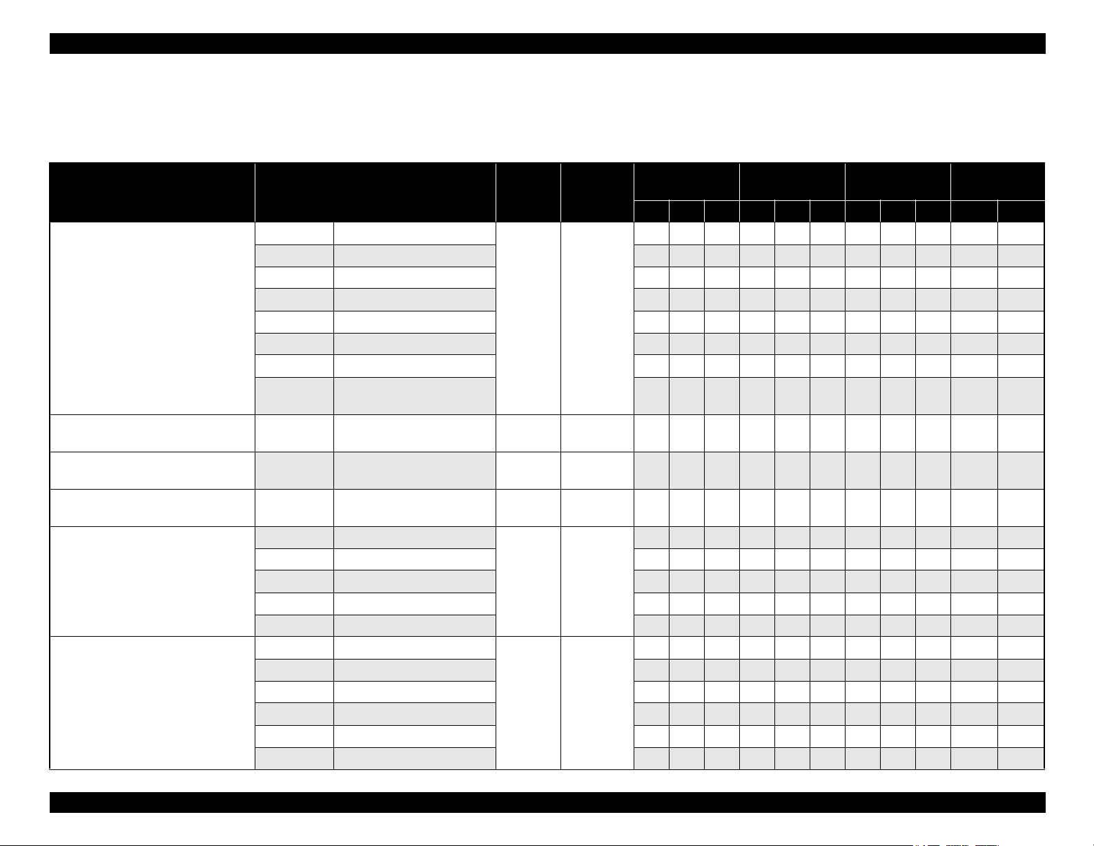
1.2.4 Supported Paper
The table below lists the paper type and sizes supported by the printer. The supported paper type and sizes vary depending on destinations (between EAI, EUR, and Asia).
Table 1-6. Supported Paper
Paper Name Paper Size
Thickness
(mm)
Legal 215.9 x 355.6 mm (8.5”x14”)
Letter 215.9 x 279.4 mm (8.5”x11”) Y - Y Y - Y Y - Y Y -
A4 210 x 297 mm (8.3”x11.7”) Y - Y Y - Y Y - Y Y -
B5 182 x 257 mm (7.2”x10.1”) - - - Y - Y Y - Y Y -
Plain paper
A5 148 x 210 mm (5.8”x8.3”) - - - Y - - Y - - Y -
0.08-0.11
Half Letter 139.7 x 215.9 mm (5.5”x8.5”) Y - - - - - - - - Y -
A6 105 x 148 mm (4.2”x5.8”) Y - - Y - - Y - - - Y
User Defined
89 x 127- 215.9 x 1117.6 mm
(3.5”x5” - 8.5”x44”)
Premium Inkjet Plain Paper A4 210 x 297 mm (8.3”x11.7”) 0.11
Premium Bright White Paper (EAI)
Letter 215.9 x 279.4 mm (8.5”x11”) 0.11
Bright White Inkjet Paper (Euro, Asia) A4 210 x 297 mm (8.3”x11.7”) 0.13
Letter 215.9 x 279.4 mm (8.5”x11”)
Ultra Premium Photo Paper Glossy
(EAI)
Ultra Glossy Photo Paper (Euro, Asia)
A4 210 x 297 mm (8.3”x11.7”) - - - Y Y - Y Y - Y -
8” x 10” 203.2 x 254 mm Y Y - - - - - - - Y -
0.30
5” x 7” 127 x 178 mm Y Y - Y Y - - - - - Y
4” x 6” 101.6 x 152.4 mm Y Y - Y Y - Y Y - - Y
Letter 215.9 x 279.4 mm (8.5”x11”)
A4 210 x 297 mm (8.3”x11.7”) Y Y - Y Y - Y Y - Y -
Premium Photo Paper Glossy (EAI)
Premium Glossy Photo Paper (Euro,
Asia)
8” x 10” 203.2 x 254 mm Y Y - - - - - - - Y -
0.27
5” x 7” 127 x 178 mm Y Y - Y Y - Y Y - - Y
4
”
x 6
”
101.6 x 152.4 mm Y Y - Y Y - Y Y - - Y
16:9 wide 101.6 x 180.6 mm Y Y - Y Y - - - - - Y
Weight
64-90 g/m
(17-24 lb.)
80 g/m
(21 lb.)
90 g/m
(24 lb.)
92.5 g/m
(25 lb.)
290 g/m
(77 lb.)
255 g/m
(68 lb.)
EAI EUR Asia
P*1B*2D*3P*1B*2D*3P*1B*2D*3Tray 1 Tray 2
Y- -Y- -Y- - Y -
2
Y - - Y - - Y - - Y
2
- - -Y-Y- - - Y -
2
Y - Y - - - - - - Y -
2
- - -Y-YY-Y Y -
Y Y - - - - - - - Y -
2
YY------- Y -
2
Paper feed tray
position
*5
*4
-
PRODUCT DESCRIPTION Printing Specifications 19
Confidential
Epson Artisan 810/835/837/710/725/730/Epson Stylus Photo PX810FW/TX810FW/PX820FWD/TX820FWD/PX830FWD/PX710W/TX710W/PX720WD/TX720WD/PX730WD/TX730WD
Revision G
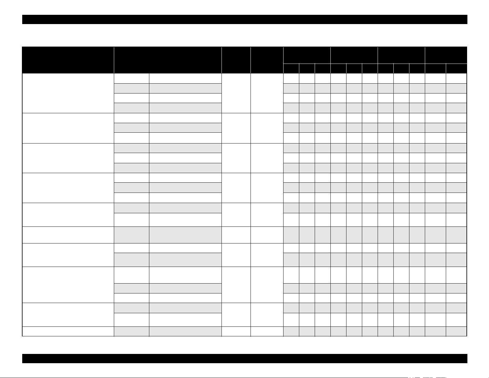
Table 1-6. Supported Paper
Paper Name Paper Size
Photo Paper Glossy (EAI)
Glossy Photo Paper (Euro, Asia)
Thickness
(mm)
Weight
Letter 215.9 x 279.4 mm (8.5”x11”)
A4 210 x 297 mm (8.3”x11.7”) Y Y - Y Y - Y Y - Y -
5” x 7” 127 x 178 mm - - - Y Y - - - - - Y
0.25
258 g/m
(68 lb.)
2
EAI EUR Asia
P*1B*2D*3P*1B*2D*3P*1B*2D*3Tray 1 Tray 2
YY------- Y -
4” x 6” 101.6 x 152.4 mm Y Y - Y Y - Y Y - - Y
Premium Photo Paper Semi-Gloss
(EAI)
Premium Semigloss Photo Paper
(Euro, Asia)
Photo Paper
Letter 215.9 x 279.4 mm (8.5”x11”)
A4 210 x 297 mm (8.3”x11.7”) - - - Y Y - Y Y - Y -
0.27
250 g/m
(66 lb.)
YY------- Y -
2
4” x 6” 101.6 x 152.4 mm Y Y - Y Y - Y Y - - Y
A4 210 x 297 mm (8.3”x11.7”)
5” x 7” 127 x 178 mm - - - Y Y - - - - - Y
0.24
190 g/m2
(51 lb.)
- - - Y Y - Y Y - Y -
4" x 6" 101.6 x 152.4 mm - - - Y Y - Y Y - - Y
Premium Presentation Paper Matte
(EAI)
Matte Paper Heavy-weight (Euro,
Asia)
Premium Presentation Paper Matte
Double-sided (EAI)
Double-sided Matte Paper (Euro, Asia)
Ultra Premium Photo Paper Luster
Presentation Paper Matte (EAI)
Photo Quality Inkjet Paper (Euro,
Asia)
Envelopes
Letter 215.9 x 279.4 mm (8.5”x11”)
A4 210 x 297 mm (8.3”x11.7”) - - - Y Y - Y Y - Y -
0.23
167 g/m
(44 lb.)
8” x 10” 203.2 x 254 mm Y Y - - - - - - - Y -
Letter 215.9 x 279.4 mm (8.5”x11”)
A4 210 x 297 mm (8.3”x11.7”) - - - Y - - Y - - - -
0.22
Letter 215.9 x 279.4 mm (8.5”x11”) 0.27
Letter 215.9 x 279.4 mm (8.5”x11”)
0.13
A4 210 x 297 mm (8.3”x11.7”) Y - - Y - - Y - - Y -
#10
#DL 110 x 220 mm - - - Y - - Y - - Y -
104.8 x 241.3 mm
(4.125”x9.5”)
-
185 g/m
(49 lb.)
250 g/m
(66 lb.)
102 g/m
(27 lb.)
75-100 g/m
(20-27 lb.)
YY------- Y -
2
Y - - - - - - - - - -
2
2
Y Y - - - - - - - Y -
Y-------- Y -
2
Y- -Y- -Y- - Y -
2
#C6 114 x 162 mm - - - Y - - Y - - Y -
Iron-On Cool Peal Transfer (EAI)
Iron-On Cool Peal Transfer Paper
(others)
Letter 215.9 x 279.4 mm (8.5”x11”)
A4 210 x 297 mm (8.3”x11.7”) - - - Y - - Y - - Y -
0.14
130 g/m
(35 lb.)
Y - - - - - - - - Y -
2
Photo Stickers 16 A6 105 x 148 mm (4.1”x5.8”) 0.19 --- - - - - - - Y - - - Y
Paper feed tray
position
*4
PRODUCT DESCRIPTION Printing Specifications 20
Confidential
Epson Artisan 810/835/837/710/725/730/Epson Stylus Photo PX810FW/TX810FW/PX820FWD/TX820FWD/PX830FWD/PX710W/TX710W/PX720WD/TX720WD/PX730WD/TX730WD
C A U T I O N
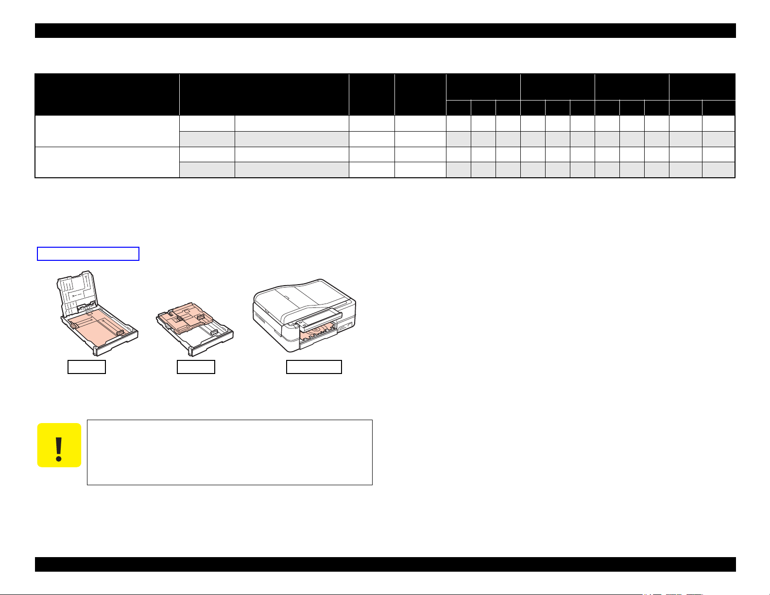
Tray 1 Tray 2 CDR Tray
Paper feed tray position
Table 1-6. Supported Paper
Paper Name Paper Size
CD/DVD
CD/DVD Premium Surface
ø12cm ø12cm --- --- Y - - Y - - Y - -
ø8cm ø8cm --- --- Y - - Y - - Y - -
ø12cm ø12cm --- --- Y - - Y - - Y - -
ø8cm ø8cm --- --- Y - - Y - - Y - -
Note *1 : “Y” in the “P” column stands for “the paper type/size is Supported”.
*2 : “Y” in the “B” column stands for “Borderless printing is available”.
*3 : “Y” in the “D” column stands for “Duplex printing is available”.
*4 : See below for the Paper feed tray position.
Thickness
(mm)
Weight
EAI EUR Asia
P*1B*2D*3P*1B*2D*3P*1B*2D*3Tray 1 Tray 2
Revision G
Paper feed tray
position
*6
*6
*6
*6
*4
-
-
-
-
*5 : The paper other than the user definition range is not supported.
*6 : Front manual paper feeding with the built-in CDR Tray
PRODUCT DESCRIPTION Printing Specifications 21
Make sure the paper is not wrinkled, fluffed, torn, or folded.
The curve of paper must be 5 mm or below.
When printing on an envelope, be sure the flap is folded neatly.
Do not use the adhesive envelopes.
Do not use double envelopes and cellophane window envelopes.
Confidential
Epson Artisan 810/835/837/710/725/730/Epson Stylus Photo PX810FW/TX810FW/PX820FWD/TX820FWD/PX830FWD/PX710W/TX710W/PX720WD/TX720WD/PX730WD/TX730WD
Print Area
LM RM
TM
BM
BM
Cut Sheet (Standard)
Cut Sheet (Borderless)
Paper SIze
LM
RM
TM
BM
Print Area
LM
RM
Print Area
Envelope
Paper Size
TM
Paper Feed Direction
Revision G
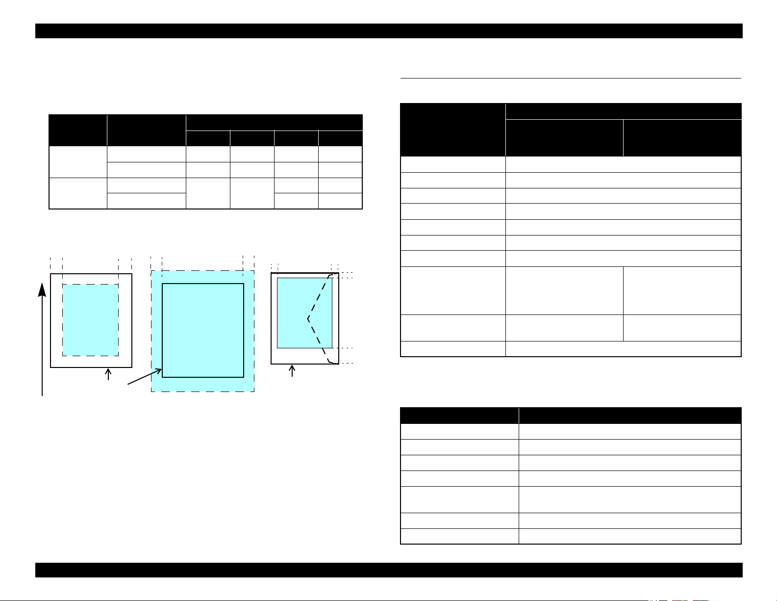
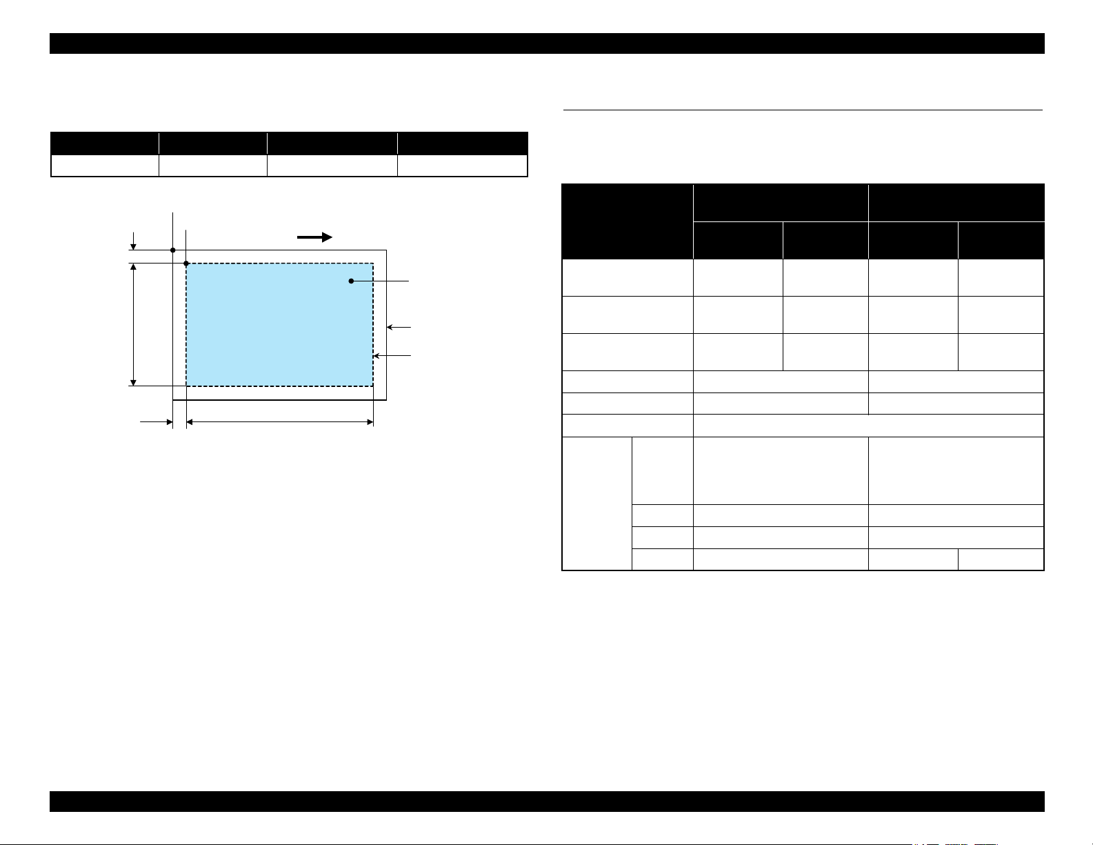
1.2.5 Printing Area
The printing area for this printer is shown below.
Table 1-7. Printing Area (Margins)
*
Print Mode Paper Size
Standard print
Any size
Envelope
Borderless
print
4” x 6”
Others
Left Right Top Bottom
3 mm 3 mm 3 mm 3 mm
5 mm 5 mm 3 mm 20 mm
2.54 mm 2.54 mm
Note * : The margins for Borderless print are margins that bleed off the edges of paper.
Margin
1.34 mm 2.54 mm
2.96 mm 4.02 mm
1.3 Scanner Specifications
Table 1-8. Basic Specifications
Specification
Item
Epson Artisan 810/Epson
Stylus Photo PX810FW/
TX810FW
Scanner type Flatbed, color
Scanning method Moving carriage, stationary document
Home position The rear left corner
Photoelectric device CIS
Light source LED
Maximum document sizes A4 or US letter
Scanning range 8.5” x 11.7” (216 mm x 297 mm)
Main scan : 4,800 dpi
Maximum resolution
Sub scan : 4,800 dpi
(1,200 dpi*)
(600 dpi*)
Maximum effective pixels 40,800 x 56,160 pixels
Pixel depth 16 bit per pixel (input) and 1 bit or 8 bit per pixel (output).
Epson Artisan 710/Epson
Stylus Photo PX710W/
TX710W
Main scan : 2,400 dpi
Sub scan : 4,800 dpi
20,400 x 28,080 pixels
(with 2,400 dpi scanning)
PRODUCT DESCRIPTION Scanner Specifications 22
Figure 1-1. Printing Area
Note * : When scanning using ADF
Table 1-9. ADF Specifications
(Epson Artisan 810/Epson Stylus Photo PX810FW/TX810FW only)
Item Specification
Document loading Face-up
Maximum document sizes A4 or US letter or Legal
Supported paper type Plain paper only
Paper thickness 64 to 95 g/m
Maximum number of
documents which can be set
30 sheets (Xerox-P 64 g/m2) or 3 mm (A4, US Letter) /
10 sheet (Legal)
Document path Feeds from upper tray and ejects to lower tray
Document set position Left back
2
Confidential
Epson Artisan 810/835/837/710/725/730/Epson Stylus Photo PX810FW/TX810FW/PX820FWD/TX820FWD/PX830FWD/PX710W/TX710W/PX720WD/TX720WD/PX730WD/TX730WD
a
RW
RL
OTM
OLM
Scanning start position
Scanning range
Scan bed
Original
(face down)
Scanning direction
Revision G
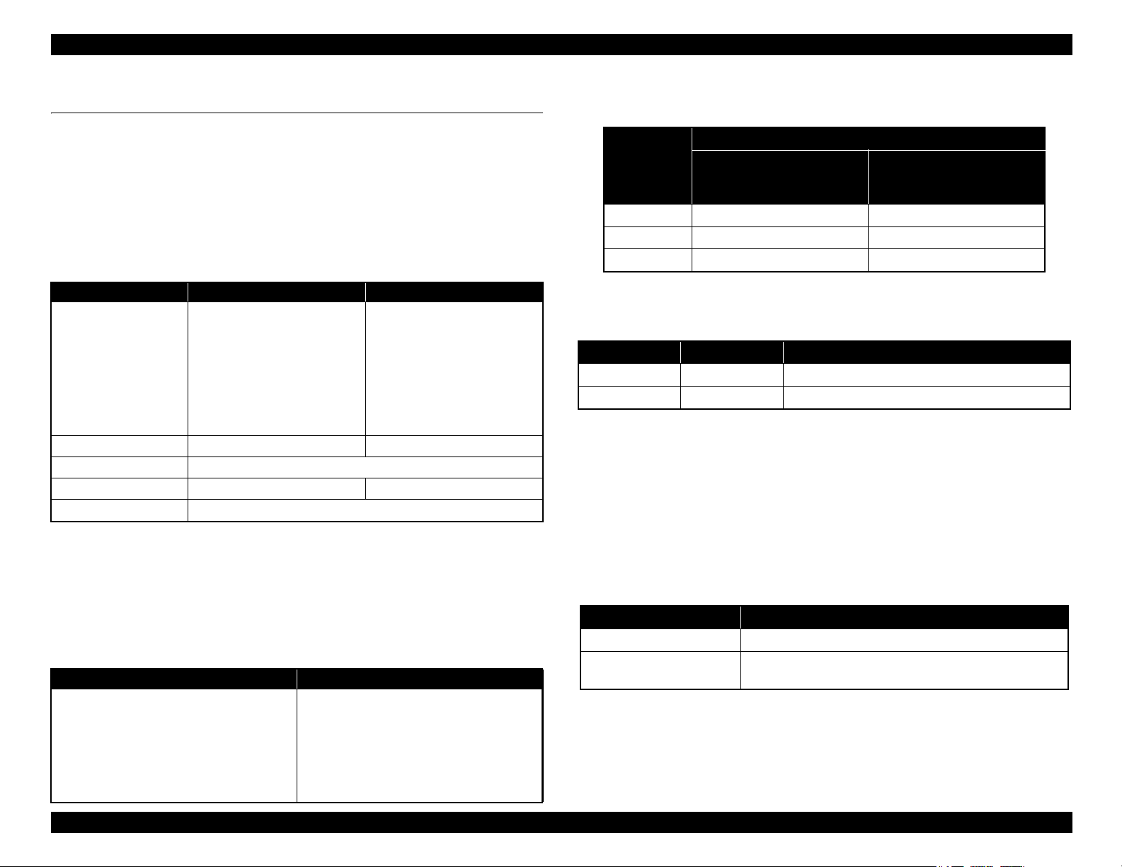
1.3.1 Scanning Range
Table 1-10. Scanning Range
RL (read length) RW (read width) OLM (left margin) OTM (top margin)
297 mm 216 mm 1.5 mm 1.5 mm
Figure 1-2. Scanning Range
1.4 General Specifications
1.4.1 Electrical Specifications
Table 1-11. Primary Power Specifications
Epson Artisan 810/Epson Stylus
Item
Rated power
supply voltage
Input voltage range
Rated current
(Max. rated current)
Rated frequency 50 to 60 Hz 50 to 60 Hz
Input frequency range 49.5 to 60.5 Hz 49.5 to 60.5 Hz
Energy conservation International Energy Star Program compliant
Copy
(ISO/
IEC24712
Power
consumption
Pattern)
Ready
Sleep
Off
Photo PX810FW/TX810FW
100-120 V
model
100 to 120
VAC
90 to 132
VAC
0.8 A
(1.6 A)
Approx. 26 W Approx. 25 W
Approx. 12 W Approx. 9.5 W
Approx. 5.5 W Approx. 5.0 W
Approx. 0.3 W Approx. 0.3 W Approx. 0.5 W
220-240 V
model
220 to 240
VAC
198 to 264
VAC
0.4 A
(0.8 A)
Epson Artisan 710/Epson Stylus
Photo PX710W/TX710W
100-120 V
model
100 to 120
VAC
90 to 132
VAC
0.8 A
(1.6 A)
220-240 V
220 to 240
198 to 264
model
VAC
VAC
0.4 A
(0.8 A)
Note : If the product has been idle status over 13 minutes, it goes into sleep mode within 2
minutes.
PRODUCT DESCRIPTION General Specifications 23
Confidential
Epson Artisan 810/835/837/710/725/730/Epson Stylus Photo PX810FW/TX810FW/PX820FWD/TX820FWD/PX830FWD/PX710W/TX710W/PX720WD/TX720WD/PX730WD/TX730WD
C A U T I O N
10/50
27/80
35/9520/68
Temperature (°C/°F)
20
30
40
50
90
80
70
60
Humidity (%)
30/86 40/104
Revision G
1.4.2 Safety Approvals (Safety standards/EMI)
USA UL60950-1
FCC Part15 Subpart B Class B
Canada CAN/CSA-C22.2 No.60950-1
CAN/CSA-CEI/IEC CISPR 22 Class B
EU EN60950-1
EN55022 Class B
EN61000-3-2, EN61000-3-3
EN55024
Germany EN60950-1
Russia GOST-R (IEC60950, CISPR 22)
*
Australia AS/NZS CISPR22 Class B
Note* : Epson Artisan 710/Epson Stylus Photo PX710W/TX710W only.
1.4.3 Acoustic Noise
Epson Artisan 810/Epson Stylus Photo PX810FW/TX810FW
PC Printing*1: TBD dB
Scanning
Epson Artisan 710/Epson Stylus Photo PX710W/TX710W
PC Printing*1: TBD dB
Scanning
Note *1: Premium Glossy Photo Paper/Highest quality
*2
: TBD dB
*2
: TBD dB
*2 : default setting
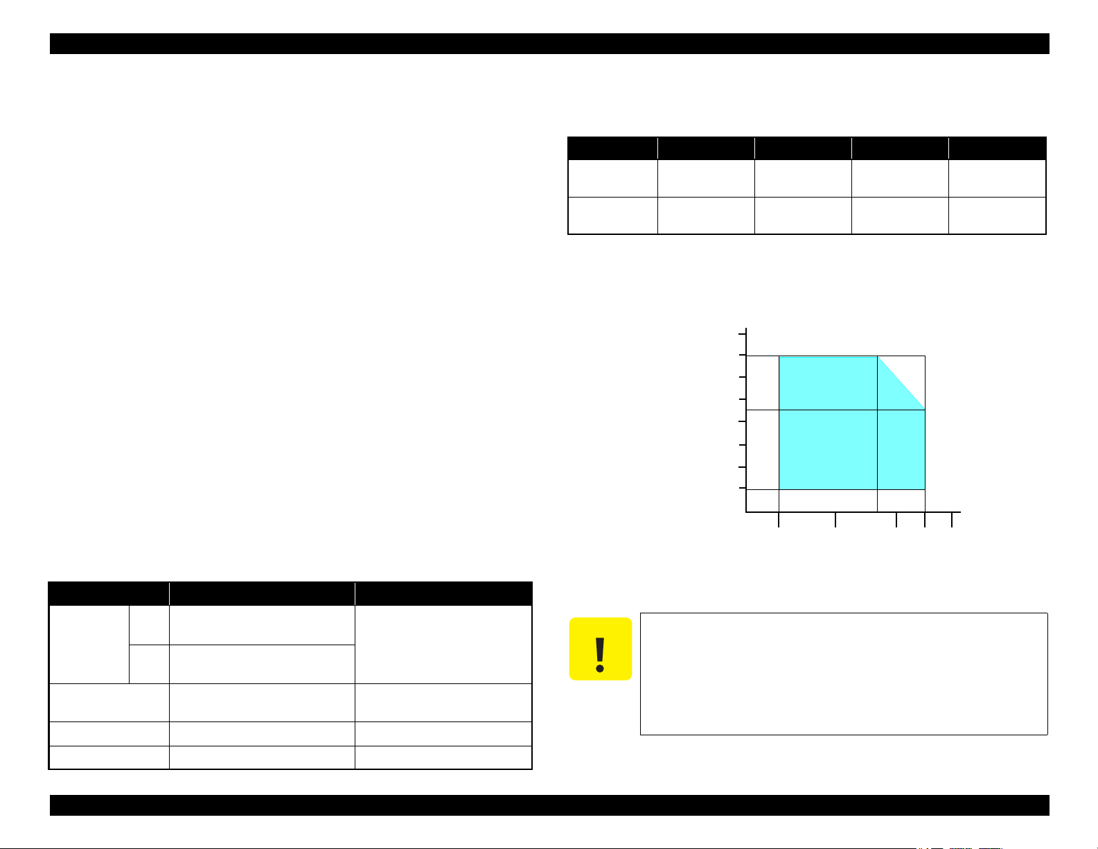
1.4.5 Environmental Conditions
Table 1-12. Environmental Conditions
°F)
*3
*1
Humidity
20 to 80%
Condition Temperature
Operating
Storage
(unpacked)
Note *1 : The combined Temperature and Humidity conditions must be within the blue-shaded
range in
*2 : No condensation
*3 : Must be less than 1 month at 40°C.
10 to 35°C
(50 to 95
-20 to 40°C
(-4°F to 104°F)
Fig.1-3.
5 to 85%
*1,2
Shock Vibration
1 G
(1 msec. or less)
2 G
(2 msec. or less)
10
10
0.15 G,
to 55 Hz
0.50 G,
to 55 Hz
1.4.4 Durability (TBD)
Item Durability Remark
Total print life
Printhead
Scanner carriage 30,000 cycles of carriage movement
Total ADF feeding*10,000 pages
Note * : Epson Artisan 810/Epson Stylus Photo PX810FW/TX810FW only.
PRODUCT DESCRIPTION General Specifications 24
16,000 pages, or five years
Black
whichever comes first
10,000 pages, or five years
Color
whichever comes first
Six billions shots (per nozzle) or
five years whichever comes first
• When printing A4 size sheet
• Black: 3.5% duty, Color: 5%
duty
Figure 1-3. Temperature/Humidity Range
When returning the repaired printer to the customer, make sure
the Printhead is covered with the cap and the ink cartridge is
installed.
If the Printhead is not covered with the cap when the printer is
off, turn on the printer with the ink cartridge installed, make
sure the Printhead is covered with the cap, and then turn the
printer off.
Confidential
Epson Artisan 810/835/837/710/725/730/Epson Stylus Photo PX810FW/TX810FW/PX820FWD/TX820FWD/PX830FWD/PX710W/TX710W/PX720WD/TX720WD/PX730WD/TX730WD
Revision G
1.5 Interface
The following is the specifications of the USB Interface, Network Interface, FAX
Interface (Epson Artisan 810/Epson Stylus Photo PX810FW/TX810FW only), and
Memory Card Slot mounted on this printer.
1.5.1 USB Interface
The table below describes the specifications of the two USB ports; USB device port for
connecting with a host such as a computer, and the USB host port for connecting with
an external devices such as a DSC (digital still camera).
Table 1-13. USB Interface Specifications
Item USB Device port USB Host port*
• Universal Serial Bus
Specifications Revision 2.0
• Universal Serial Bus Device
Compatible standards
Transfer rate
Class Definition for Printing
Devices Version 1.1
• Universal Serial Bus Mass
Storage Class Bulk-Only
Transport Revision 1.0
480 Mbps (High Speed) 480 Mbps (Max.)
Data format
Compatible connector
Max. cable length
Note* : The following devices can be connected to the USB Host port.
• Devices compliant with DPS Version 1.0/1.1 (PictBridge)
• Devices compliant with Universal Serial Bus Mass Storage Class Bulk-Only Transport
Revision 1.0, and the Subclass code is one of the followings.
0x06 (SCSI transparent command set)
0x05 (SFF-8070i command set)
0x02 (SFF-8020i command set)
USB Series B USB Series A
Table 1-14. Device ID
When IEEE 1284.4 is Enabled When IEEE 1284.4 is Disabled
@EJL<SP>ID<CR><LF>
MFG:EPSON;
CMD:ESCPL2,BDC,D4,D4PX, ESCPR2;
MDL:Model Name;
CLS:PRINTER;
DES:EPSON<SP>Model Name;
CID:EpsonRGB;
@EJL<SP>ID<CR><LF>
MFG:EPSON;
CMD:ESCPL2,BDC, ESCPR2;
MDL:Model Name;
CLS:PRINTER;
DES:EPSON<SP>Model Name;
CID:EpsonRGB;
• Universal Serial Bus
Specifications Revision 2.0
NRZI
2 [m] or less
Note : The “Model Name” is replaced as shown in the following table.
Table 1-15. Model Names Indicated in the Device ID
Model Name
Destination
North America Artisan 810 Artisan 710
Euro Epson Stylus Photo PX810FW Epson Stylus Photo PX710W
Asia/Pacific Epson Stylus Photo TX810FW Epson Stylus Photo TX710W
Epson Artisan 810/Epson
Stylus Photo PX810FW/
TX810FW
Epson Artisan 710/Epson
Stylus Photo PX710W/
TX710W
1.5.2 FAX Interface (Epson Artisan 810/Epson Stylus
Photo PX810FW/TX810FW only)
Port Name Connector Description
Line port RJ11 Connects to phone cable from modular wall jack.
EXT port RJ11 Connects to TAM or Telephone.
1.5.3 Network Interface
Epson Artisan 810/Epson Stylus Photo PX810FW/TX810FW/Epson Artisan 710/
Epson Stylus Photo PX710W/TX710W
or Wireless LAN connectio
n, however, they can not be used simultaneously.
The following describes each Interface.
Wired LAN
The following interface is equipped for the Wired LAN connection. The communication
mode can be selected from auto setting or fixed setting.
Table 1-16. Wired LAN
Item Content
Connector RJ-45 receptacle*: 1 port
Communication Speed For either 10Base-T or 100Base-TX, the Full Duplex or Half
Duplex can be selected.
Note* : 10Base-T/100Base-TX Ethernet is supported. MDI/MDI-X is selected automatically.
can be connected to the network via Wired
PRODUCT DESCRIPTION Interface 25
Confidential
Epson Artisan 810/835/837/710/725/730/Epson Stylus Photo PX810FW/TX810FW/PX820FWD/TX820FWD/PX830FWD/PX710W/TX710W/PX720WD/TX720WD/PX730WD/TX730WD
C H E C K
P O I N T
Revision G
Table 1-17. Combination of the Wired LAN communication mode settings
Setting of this printer Setting of the connected device
Auto Setting (AUTO)
Auto Setting
100BASE-TX Full Duplex 100BASE-TX Full Duplex
100BASE-TX Half Duplex
10BASE-T Full Duplex 10BASE-T Full Duplex
10BASE-T Half Duplex
100BASE-TX Half Duplex
10BASE-T Half Duplex
Auto Setting (AUTO)
100BASE-TX Half Duplex
Auto Setting (AUTO)
10BASE-T Half Duplex
Wireless LAN
The following interface is equipped for the Wireless LAN connection.
Table 1-18. Wireless LAN
Item Content
Applied Standard
(2.4GHz spectrum band
wireless network
standards)
Wireless Operation Mode IEEE802.11b DS-SS (Half Duplex)
Communication Range
(line-of-sight distance)
Communication Mode Ad-hoc (IBSS) or Infrastructure (ESS)
Roaming Function Not supported
Output Signal Intensity 10 mW
Antenna Built-in antenna (Diversity function is supported)
Conforms to IEEE802.11b, IEEE802.11g
IEEE802.11g OFDM (Half Duplex)
IEEE802.11b (11 Mbps) • 60 m (indoor)
*
IEEE802.11g (54 Mbps) • 20 m (indoor)
• 220 m (outdoor)
• 100 m (outdoor)
Table 1-19. Available Channels and Standard
Frequency Band
(GHz)
2.400 - 2.4835 1 - 13 802.11b 11/5.5/2/1 M
2.400 - 2.4835 1 - 13 802.11g 54/48/36/24/18/12/9/6 M
2.471 - 2.497 14 802.11/11b 11/5.5/2/1 M
Note " * " : The communication speed will be changed automatically, depending on radio wave
strength. bps = bit per second.
Channel IEEE Standard
Communication Speed
(bps)*
Switching Wired/Wireless LAN
This printer can be connect to the network via either Wired LAN or Wireless LAN
connection only.
Enabling/disabling the Wireless LAN can be made from the Control Panel. When the
Wireless LAN is enabled, it gets priority over the Wired LAN regardless of whether
the LAN Cable is connected. The default Wireless LAN setting is “Disabled”.
Table 1-20. Wireless LAN Setting from the Control Panel
Setting from Control Panel
Wireless LAN Disabled
(Default)
Enabled
Note* : No service via network is available without connecting the LAN Cable (because
network communication is not established) except printing a status sheet or the like.
LAN Cable Connection State
Connected Disconnected
Wired LAN ---
Wireless LAN
*
Wireless LAN
When changing the networks while the power is on, wait at least for
10 seconds between disconnecting and reconnecting.
Note * : Referential value. It depends on surrounding conditions.
PRODUCT DESCRIPTION Interface 26
Confidential
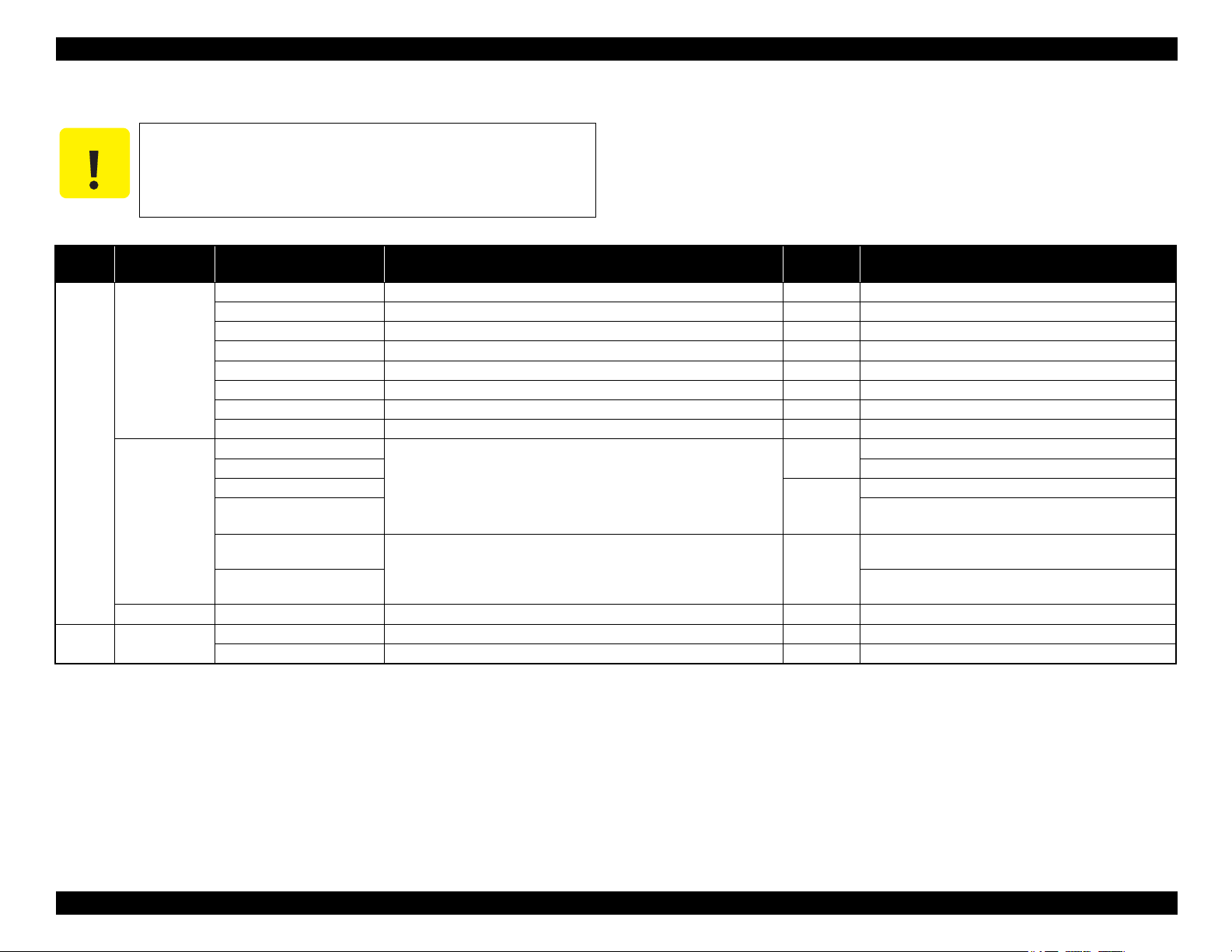
Epson Artisan 810/835/837/710/725/730/Epson Stylus Photo PX810FW/TX810FW/PX820FWD/TX820FWD/PX830FWD/PX710W/TX710W/PX720WD/TX720WD/PX730WD/TX730WD
C A U T I O N
1.5.4 Memory Card Slots
If you insert a Memory Stick DUO to the Memory Card Slot
without using the adapter, make sure to turn off the printer first,
then remove the card using tweezers.
Table 1-21. List of Supported Memory Card
Priority Slot Compatible memory card Standard
1 Memory Stick/
Memory Stick
PRO
SD/MMC SD (Security Digital) SD Memory Card Specifications / PART1. Physical Layer Specification Ver.
xD-Picture card
2 CF Type II Compact Flash CompactFlash Specification Revision 2.1 compatible 32GB True-IDE compatible memory card only
Memory Stick MemoryStick Standard Format Specification Ver.1.43-00 compatible 128MB Includes versions with memory select function
MagicGate Memory Stick --- --- Copy protection function is not supported
MagicGate Memory Stick Duo --- --- The Memory Stick Duo adapter should be used.
Memory Stick PRO Memory Stick Pro Format Specifications Ver.1.02-00 compatible 32GB Copy protection function is not supported
Memory Stick Duo MemoryStick Duo Format Specification Ver.1.10-00 compatible --- The Memory Stick Duo adapter should be used
Memory Stick Pro Duo --- --- The Memory Stick Duo adapter should be used.
Memory Stick micro --- --- The Memory Stick adapter for standard size should be used.
Memory Stick Pro-HG Duo --- --- The Memory Stick Duo adapter should be used.
miniSD/microSD The SD adapter should be used
SDHC 32GB Speed Class is not supported
miniSDHC/microSDHC The SD adapter should be used
MultiMediaCard
MultiMediaCard Plus
MultiMediaCard mobile
MultiMediaCard micro
*
xD-Picture card xD-Picture Card Specification Ver.1.2 compatible 2GB Type M/H supported
Microdrive --- --- ---
2.0 compatible
MultiMediaCard Standard Ver. 4.2 compatible 4GB/32MB Only MultiMediaCard Plus supports up to 32GB.
Max.
capacity
2GB ---
Speed Class is not supported
The Multi Media Card adapter for standard size should be
used.
Remarks
Revision G
Note* : FAT32 is not specified in the xD-Picture card standards. This printer supports only reading of xD-Picture card formatted in FAT32.
Note: • Memory Stick/PRO, SD/MMC and xD-Picture Card shares the same slot.
• When cards are inserted in the two slots at once, the slot which will be accessed first is determined according to the priority shown in the table.
• To select a card that has been inserted in a non-active slot, first remove the card in the active slot.
• In memory card direct printing mode, the image files in the active slot are valid and have assigned frame numbers. The number of images will not change if a card is inserted in another nonselected slot.
• When the card inserted in the slot is accessed from the PC, only one drive is displayed at a time as a removable disk* and only the card that is in the active slot can be accessed via the
removable disk. A card that has been inserted into a non-selected slot cannot be accessed. (This is for Windows. For Macintosh, the card in the active slot will be mounted on the desktop.)
• Does not support 5V type of memory cards.
• When a memory card is being accessed, do not touch the memory card.
• For detailed information on the supported file system and formatting the memory card, refer to " 1.7.2 Memory Card Direct Print Function (Photos Mode) ( p. 33 ) ".
PRODUCT DESCRIPTION Interface 27
Confidential
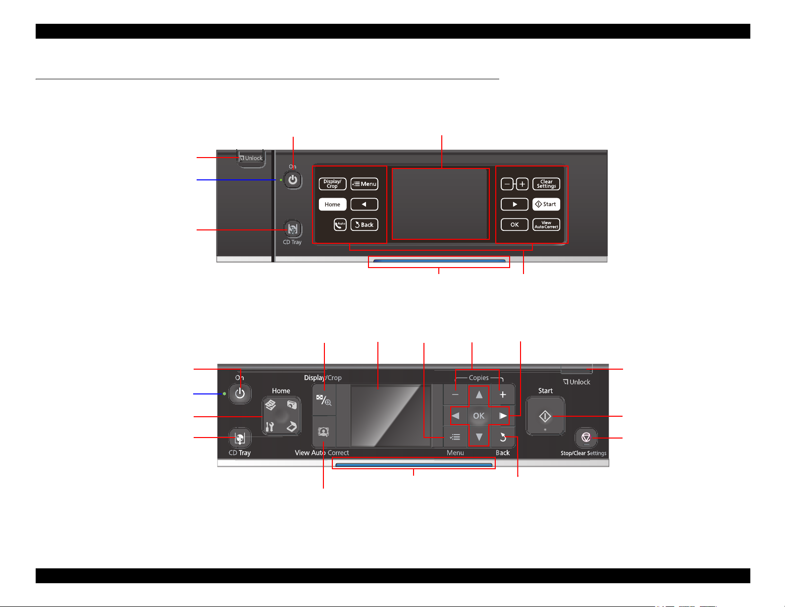
Epson Artisan 810/835/837/710/725/730/Epson Stylus Photo PX810FW/TX810FW/PX820FWD/TX820FWD/PX830FWD/PX710W/TX710W/PX720WD/TX720WD/PX730WD/TX730WD
LCD
Power LED
Power Button
CD Tray button
Touch Panel
Unlock button
Blue status light
LCD
Home button
Display/Crop button
Cross Key and OK button
Menu button
Start button
Stop/Clear Settings button
-, + button
View Auto Correct button
Unlock button
CD Tray button
Power button
Power LED
Back button
Blue status light
1.6 Control Panel
1.6.1 Operation Buttons & LEDs
Figure 1-4. Control Panel for Epson Artisan 810/Epson Stylus Photo PX810FW/TX810FW (EAI version as a sample)
Revision G
Figure 1-5. Control Panel for Epson Artisan 710/Epson Stylus Photo PX710W/TX710W (EAI version as a sample)
PRODUCT DESCRIPTION Control Panel 28
Confidential
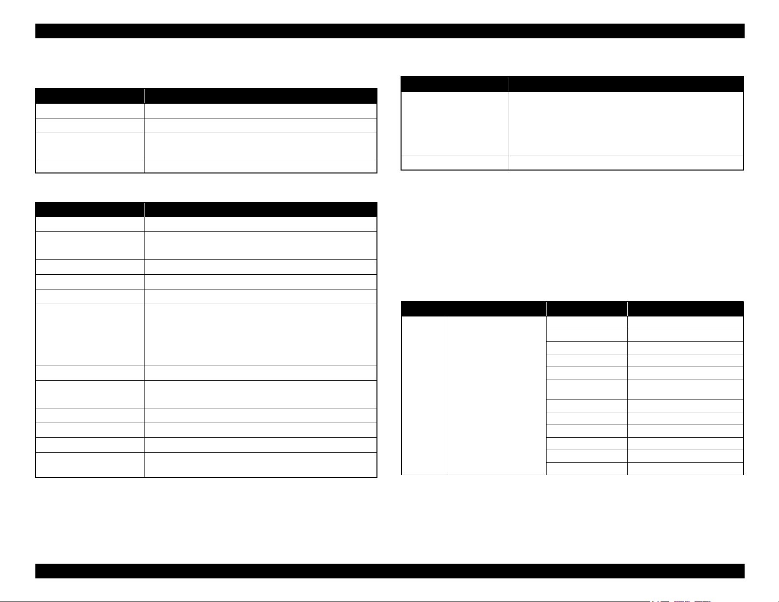
Epson Artisan 810/835/837/710/725/730/Epson Stylus Photo PX810FW/TX810FW/PX820FWD/TX820FWD/PX830FWD/PX710W/TX710W/PX720WD/TX720WD/PX730WD/TX730WD
Revision G
Table 1-22. Button Functions
(Epson Artisan 810/Epson Stylus Photo PX810FW/TX810FW)
Button Function
Power Turns the power ON/OFF.
Touch Panel Displays available buttons in each mode.
Unlock button
CD Tray Ejects/retracts the CDR Tray.
Release the lock of tilt adjustment of the Control Panel while
pressing.
Table 1-23. Button Functions
(Epson Artisan 710/Epson Stylus Photo PX710W/TX710W)
Button Function
Power
Display/Crop
-, + Sets pages to print
Unlock Release the lock of the Control Panel.
Start Starts printing.
Stop/Clear Settings
Back Cancels the previous operation.
Cross Key/OK
Menu Goes to the menu screen for each mode.
Auto Correct Changes the Auto Correct ON/OFF.
CD Tray Ejects/retracts the CDR Tray.
Home
Turns the power ON/OFF.
• Goes to the zoom setting screen for the selected image.
• Changes the image preview layout on the LCD.
• Stops operation and displays the menu screen.
• Stops printing and ejects paper.
• Returns the print settings in the current mode to their defaults
and displays the Top screen. (Returns to the previous screen
during printing maintaining the current settings)
• Selects a menu item or a setting value.
• Accepts the changed settings
Changes modes in the following order.
Copy/Print Photos/Scan/Setup
Table 1-24. LED
LED Function
• Flashes while powering ON/OFF.
• Flashes during some sequence is in progress.
Power (Green)
Blue status light Flashes or lights according to the printer status.
• Flashes when a fatal/maintenance error occurs.
• Lights when the status is other than above.
(Stand by mode/during setting on the Panel, etc.)
1.6.2 Control Panel Functions in Each Mode
1.6.2.1 Control Panel Functions
The table below shows the print setting menu items for each mode and their defaults,
and when the settings are saved or returned to their defaults. Explanations on detailed
control panel functions of the Epson Artisan 810/Epson Stylus Photo PX810FW/
TX810FW/Epson Artisan 710/Epson Stylus Photo PX710W/TX710W are omitted
here, because the LCD displays the detailed instruction.
Table 1-25. Timing of Saving or Initializing Control Panel Settings
Mode Print Setting Default Value
Copy Normal Copy Copy Type Color
Density ±0
Layout With Border
2-Sided Printing Off
Reduce/Enlarge Actual
Paper Size
Paper Type Plain Paper
Document Type Text & Image
Quality Standard Quality
Expansion Standard
Dry Time Standard
Binding Direction Vertical-Long
• EAI: Letter
• Euro/Asia: A4
PRODUCT DESCRIPTION Control Panel 29
Confidential

Epson Artisan 810/835/837/710/725/730/Epson Stylus Photo PX810FW/TX810FW/PX820FWD/TX820FWD/PX830FWD/PX710W/TX710W/PX720WD/TX720WD/PX730WD/TX730WD
Revision G
Table 1-25. Timing of Saving or Initializing Control Panel Settings
Mode Print Setting Default Value
Copy Photo Copy Color Restoration Off
Paper Size 4” x 6” (10 x 15 cm)
Paper Type Prem. Glossy
Boderless On
Expansion Standard
Fix Photo
Enhance
Filter Off
CD/DVD Print CD Inner/Outer Standard
Print Type Print on a CD/DVD
Document Type Text & Image
Quality Best
Print Photo • View and Print Photos
• Print All Photos
Paper Size 4” x 6” (10 x 15 cm)
Paper Type Prem. Glossy
Borderless On
Layout Boderless
Quality Standard Quality
Expansion Standard
Date Off
Print Info. On Photos Off
Fit Frame On
Bidirectional On
Fix Photo
Enhance
Scene Detection Automatic
Fix Red-Eye Off
Filter Off
Brightness Standard
Contrast Standard
Sharpness Standard
Saturation Standard
Print Photo Print Photo Greeting Card Paper Size
Paper Type Prem. Glossy
*1
*2
*1
*2
Fix Photo Off
Enhance Off
Fix Photo On
PhotoEnhance
*3
• EAI: Letter
• Euro/Asia: 4” x 6” (10 x 15 cm)
Table 1-25. Timing of Saving or Initializing Control Panel Settings
Mode Print Setting Default Value
Print Photo Print Photo Greeting Card Layout
Frame Off
Fix Photo
Enhance
Scene Detection Automatic
Fix Red-Eye Off
Filter Off
Brightness Standard
Contrast Standard
Sharpness Standard
Saturation Standard
Photo Layout Sheet Layout 2-up
Paper Size 4” x 6” (10 x 15 cm)
Paper Type Prem. Glossy
Layout Method Automatic layout
Photo Layout Place this photo
Quality Standard Quality
Expansion Standard
Date Off
Print Info. On Photos Off
Fit Frame On
Bidirectional On
Print on CD/DVD Layout CD/DVD 1-up
Layout Method Automatic layout
Photo Layout Place this photo
CD Inner/Outer Standard
Print Type Print on a CD/DVD
CD Density Standard Density
Fix Photo
Enhance
Scene Detection Automatic
Fix Red-Eye Off - This photo
Filter Off
Brightness Standard
Sharpness Standard
Saturation Standard
*1
*2
*1
*2
• EAI: 3-up
• Euro/Asia: Borderless
Fix Photo On
PhotoEnhance
Fix Photo On
PhotoEnhance
PRODUCT DESCRIPTION Control Panel 30
Confidential
 Loading...