


 Loading...
Epson BrightLink 575Wi, BrightLink 585Wi, PowerLite 570, PowerLite 575W, PowerLite 580 Installation Guide
...Installation Guide Guide d’installation
Safety Instructions
For your safety, read all the instructions in this guide before using the wall mount. Incorrect handling that ignores instructions in this guide could damage the wall mount or could result in personal injury or property damage. Keep this installation guide on hand for future reference.
Read the safety instructions in the User's Guide for your projector and follow the instructions in this document.
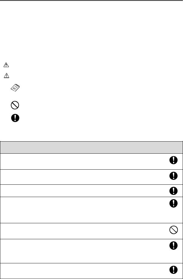
Explanation of Symbols
The warning marks shown below are used throughout this installation guide to prevent personal injury or property damage. Make sure you understand these warnings when reading this installation guide.
Warning |
This symbol indicates information that, if ignored, could possibly result in personal injury or even death |
due to incorrect handling. |
|
|
|
Caution |
This symbol indicates information that, if ignored, could possibly result in personal injury or physical |
damage due to incorrect handling. |
|
|
|
|
This symbol indicates related or useful information. |
|
|
|
|
|
Symbol indicating an action that must not be done |
|
|
|
Symbol indicating an action that should be done |
|
|
Safety Precautions for Installation
 Warning
The wall mount is designed specifically for mounting a projector to a wall. If anything other than a projector is mounted, the weight may result in damage.
If the wall mount falls, it could cause personal injury or property damage.
The installation work (wall mounting) should be performed by specialists who have technical knowledge and ability. Incomplete or incorrect installation could cause the wall mount to fall and cause personal injury or property damage.
Follow the instructions in this guide when installing the wall mount.
If the instructions are not followed, the wall mount may fall, resulting in personal injury or property damage.
Handle the power cord carefully.
Incorrect handling may cause fire or electric shock. Observe the following precautions when handling:
•Do not handle the power plug with wet hands.
•Do not use a power cord that is damaged or modified.
•Do not pull the power cord with too much force when routing the cable through the wall mount.
Do not install the wall mount in a place where it might be subjected to vibration or shock.
Vibration or shock could cause damage to the projector or mounting surface. It could also cause the wall mount or projector to fall and cause personal injury or property damage.
Install the wall mount so that it can sufficiently support the weight of the projector and wall mount, and resist any horizontal vibration. Use M10 nuts and bolts and make sure to use appropriate wall anchors for your wall type.
Nuts and bolts smaller than M10 could cause the wall mount to fall. Epson accepts no responsibility for any damage or injury caused by lack of wall strength or inadequate installation.
The installation work should be performed by at least two qualified service personnel. If you need to loosen any screws during installation, be careful not to drop the wall mount.
If the wall mount or projector falls, it could cause personal injury or property damage.
2

Warning |
|
When you mount the projector on the wall with the wall mount, the wall requires enough strength to hold |
English |
mount before installation, and maintain the strength of the wall. If the wall is not strong enough, reinforce |
|
the projector and the wall mount. |
|
This wall mount should be installed on a concrete wall. Confirm the weight of the projector and the wall |
|
the wall before installation. |
|
Inspect the wall mount on a regular basis to ensure there are no broken parts or loose screws. |
|
If there are any broken parts, stop using the wall mount immediately. If the wall mount or projector falls, it could cause personal injury or property damage.
Never modify the wall mount.
Do not hang on the wall mount or hang a heavy object on the wall mount.
If the projector or wall mount falls, it could cause personal injury or property damage.
Do not use adhesives, lubricants, or oils to install or adjust the wall mount. If you use adhesives to prevent the screws from loosening or things such as lubricants or oils on the part of the projector attached to the slide plate, the case may crack and cause the projector to fall, resulting in personal injury or property damage.
Tighten all screws firmly after adjustment.
Otherwise, the projector or wall mount may fall and cause personal injury or property damage.
Never loosen the bolts and nuts after installation.
Confirm that the screws have not become loose on a regular basis. If you find any loose screws, tighten them firmly. Otherwise, the projector or wall mount may fall and cause personal injury or property damage.
When performing wiring, make sure the cable does not come into contact with any screws or bolts.
Handling the cable incorrectly may cause fire or electric shock.
 Caution
Do not install the wall mount in a location where the operating temperature for your projector model may be exceeded. Such an environment may damage the projector.
Install the wall mount in a place free from excessive dust and humidity to prevent the lens or optical components from becoming dirty.
Do not use excessive force when adjusting the wall mount.
The wall mount may break, resulting in personal injury.
Location
•Before installing the projector, verify the power supply wiring for the installation location.
•Install the projector away from other electric devices such as fluorescent lights or air conditioners. Some kinds of fluorescent lights could interfere with the remote control of the projector.
•Install the projector away from direct sunlight and other bright light sources.
•It is recommended to keep VGA computer cable length less than 65 ft (20 meters) to reduce external noise.
About This Installation Guide
This guide describes how to mount the ultra-short-throw projectors BrightLink 575Wi/585Wi/575Wi+/585Wi+ and PowerLite 570/575W/580/585W to a wall using the included Epson wall mount.
3

1 |
Package Contents |
s 5 |
|
|
|
|
|
|
|
|
|
2 |
Specifications |
s 6 |
|
|
|
|
|
|
|
|
|
3 |
Connecting Devices |
s 8 |
|
|
|
|
|
|
|
|
|
4 |
Positioning the Projector |
s 9 |
|
|
1. |
Installation worksheet for projecting on a pre-installed wall-mounted board |
|
|
2. |
Installation worksheet for projecting on a plain wall |
|
|
3. |
Installation measurements in inches |
|
|
4. |
Installation measurements in millimeters |
|
|
|
|
|
|
|
|
|
5 |
Installing the Projector |
s 23 |
|
1.Disassemble the parts
2.Assemble the parts
3.Install the wall plate on the wall
4.Determine the projection distance and pull out the slider
5.Route the cables through the wall mount arm
6.Attach the mount arm to the wall plate
7.Adjust the vertical slide position of the arm
8.Attach the projector to the wall mount
9.Connect the power cord and other cables to the projector
6 |
Adjusting the Image |
s 34 |
|
|
1. |
Turn on the projector |
|
|
2. |
Display the test pattern |
|
|
3. |
Change the aspect ratio if necessary |
|
|
4. |
Adjust the focus |
|
|
5. |
Use the adjustment knob on the left side to adjust the horizontal roll |
|
|
6. |
Use the adjustment knob on the right side to adjust the horizontal rotation |
|
|
7. |
Use the adjustment knob on the top to adjust the vertical tilt |
|
|
8. |
Adjust the horizontal slide |
|
|
9. |
Adjust the forward/backward slide |
|
|
10. |
Adjust the vertical slide |
|
|
11. |
Turn off the display of the test pattern |
|
|
|
|
|
|
|
|
|
7 |
Attaching the Covers |
s 40 |
|
1.Attach the wall plate cover and end cap
2.Attach the cable cover to the projector
4
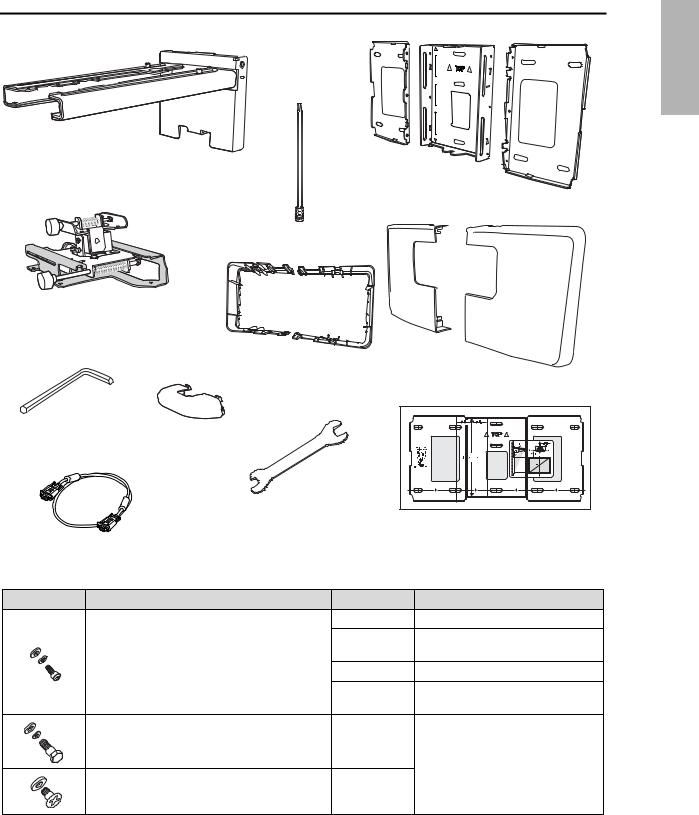
1 Package Contents
English |
Wall mount
Wall plate
Hexagonal shaft
3-axis adjustment unit and slide plate (attached when shipped)
Wall plate cover extender
Wall plate cover
Hexagon wrench (for M4)
End cap
|
|
Open-ended wrench |
|
|
|
|
13 mm (for M8 and M6) x |
Template sheet |
|
|
|
6 mm (for hexagonal |
|
(for installing the wall plate) |
VGA computer cable (may be included |
shaft) |
|
|
|
with projector or wall mount) |
|
|
|
|
Shape |
Name |
|
Quantity |
Application |
|
M4 x 12 mm hexagon socket head cap bolt with |
6 |
For wall plate assembly |
|
|
washer/spring washer |
|
4 |
For 3-axis adjustment unit/wall mount |
|
|
|
||
|
|
|
|
installation |
|
|
|
4 |
For slide plate/projector installation |
|
|
|
2 |
For slide plate/3-axis adjustment unit |
|
|
|
|
installation (secured when shipped) |
|
M6 x 20 mm hexagon shoulder bolt with washer/ |
1 |
For wall mount/wall plate installation |
|
|
spring washer |
|
|
|
|
M6 x 20 mm cross recessed head shoulder screw |
3 |
|
|
|
with plastic washer |
|
|
|
•Use the bolts or screws supplied with the wall mount to install it as directed in this guide. Do not substitute these bolts with any other types.
•You need to use commercially available M10 x 60 mm anchors (at least 3) to attach the wall plate to the wall.
•Gather the tools and parts you need before you begin installation, including a #3 cross-head screwdriver.
5

2 Specifications
Item |
Specification |
Additional information |
Reference |
|
|
|
Page |
|
|
|
|
Wall mount weight (including the |
Approx. 18.5 lb |
Wall mount: 6.6 lb (3.0 kg) |
— |
3-axis adjustment unit, slide plate, |
(8.4 kg) |
3-axis adjustment unit: 2.6 lb (1.2 kg) |
|
wall plate, wall plate cover, wall |
|
Slide plate: 1.8 lb (0.8 kg) |
|
plate cover extender, and end cap) |
|
Wall plate: 6.0 lb (2.7 kg) |
|
|
|
Wall plate cover and end cap: 0.9 lb (0.4 kg) |
|
|
|
Wall plate cover extender: 0.6 lb (0.3 kg) |
|
|
|
|
|
Maximum load capacity |
15.4 lb (7 kg) |
— |
— |
|
|
|
|
Vertical slide adjustment range |
± 1.5 in. (38 mm) |
— |
Refer to the |
|
|
|
illustration |
|
|
|
below |
|
|
|
|
Horizontal slide adjustment range |
± 1.8 in. (45 mm) |
— |
Refer to the |
|
|
|
illustration on |
|
|
|
page 7 |
|
|
|
|
Forward/backward slide |
0 to 14.2 in. |
Arm slide adjustment range: 0 to 10.7 in. (273 mm) |
Refer to the |
adjustment range |
(360 mm) |
Adjustment from 3-axis adjustment unit installation |
illustration on |
|
|
position: 3.4 in. (87 mm) |
page 7 |
|
|
|
|
Horizontal roll adjustment range |
± 3° |
Fine adjustments possible with adjustment knob |
s 36 |
|
|
|
|
Horizontal rotation adjustment |
± 8° |
Fine adjustments possible with adjustment knob |
s 37 |
range |
|
|
|
|
|
|
|
Vertical tilt adjustment range |
± 3° |
Fine adjustments possible with adjustment knob |
s 37 |
|
|
|
|
Wall plate
The wall plate is in three pieces when shipped. Use the included M4 x 12 mm bolts (x6) to attach the separate pieces together before mounting the projector. See page 24 for instructions.
5.1 in. |
|
|
6.3 in. (160 mm) |
8.4 in. (213mm) |
8.7 in. (222mm) |
9.7 in. (246mm) |
(130 mm) |
|
3.1 in. (79 mm) |
||||
|
1.2 in. |
|||||
|
(30.6 mm) |
|||||
1.0 in. |
|
|||||
(25 mm) |
|
|||||
|
2.4 in. |
|
|
|
|
|
|
|
(60 mm) |
|
|
|
|
|
|
|
1.3 in. |
|
|
|
|
|
4.6 in. |
(33 mm) |
|
|
|
3.2 in. |
4.2 in. |
|
|
|
|
|
(117 mm) |
|
|
|
|
||
(80 mm) |
(106.5 mm) |
|
|
|
|
|
|
|
|
|
|
||
|
|
8.8 in. (223 mm) |
|
|
|
|
|
19.5 in. (496 mm) |
|
|
|
|
|
Vertical slide adjustment range
1.5 in. (38 mm)
1.5 in. (38 mm) |
6

Horizontal slide adjustment range
English |
1.8 in. (45 mm) |
1.8 in. (45 mm) |
Forward/backward slide adjustment range
Arm slide adjustment range
10.7 in. (273 mm) |
Adjustment from 3-axis adjustment unit installation position
By changing the installation position of the 3-axis adjustment unit to the front or back, you can adjust the installation position of the projector.
When the screen size is less than 75 inches, install it at the position marked with a  stamp on the mount arm.
When the screen size is 75 inches or more, install it at the position marked with a  stamp on the mount arm.
To see these stamps, you need to remove the two top screws and slide out the arm extension.
 stamp
stamp
 stamp
stamp
3.4 in.
(87 mm)
7

3 Connecting Devices
Make sure you have the power cord, computer cable, and other parts at the location where the wall mount is to be installed.
Make sure you also have all necessary cables for devices, such as a document camera or microphone, that you will connect to the projector. For details, refer to the online User’s Guide.
Connection Example
External speakers |
LAN device |
|
LAN cable (not included)
Audio cable |
|
(not included) |
Computer cable |
|
|
|
(for computer video output) |
Microphone |
|
|
Computer |
Document camera |
USB cable |
(for Easy Interactive Function |
|
(Epson DC-06) |
on BrightLink models only) |
|
Dedicated USB cable |
|
(supplied with document camera) |
For Interactive Use (BrightLink 575Wi/585Wi/575Wi+/585Wi+ only)
When interacting with a computer, you need a USB cable.
However, when using the projector's built-in toolbar, you do not need a USB cable.
8

4 |
Positioning the Projector |
English |
|
BrightLink 575Wi/585Wi/575Wi+/585Wi+ and PowerLite 575W/585W can project up to 100 inches diagonally |
|||
|
|||
for a WXGA image or 88 inches diagonally for an XGA image. PowerLite 570/580 can project up to 93 inches |
|
||
diagonally for an XGA image. You can project onto a pre-installed whiteboard or directly onto a plain wall. The |
|
||
height of the included wall mount determines the maximum image size and how high the image appears on |
|
||
the wall or whiteboard. The distance of the projector from the wall (once it is mounted on the adjustable arm |
|
||
of the wall mount) also affects image size and position. |
|
||
If you are planning to project on a whiteboard, the image may not fill the entire board, depending on the aspect ratio. If you match the image height to the board’s height, gaps may appear on the sides of the board.
Use the following worksheets to determine the proper location of the wall plate on the wall. If you are projecting onto a pre-installed whiteboard, use the worksheet below. If you are projecting on a plain wall, use the worksheet on page 10.
Installation worksheet for projecting on a pre-installed wall-mounted board
1. |
Measure the ceiling height (distance from the floor to the ceiling). |
_____ |
2. |
Measure the height of the board’s image area (h). |
_____ (h) |
3. |
Measure the width of the board’s image area (w). |
_____ (w) |
4. |
Measure the distance from the floor to the bottom of the board’s image area (f). |
_____ (f) |
5. |
Measure the distance from the ceiling to the top of the board’s image area (d). |
_____ (d) |
6.Measure the thickness of the board (distance from the projection surface to the wall) (x). _____ (x)
10 in. (254 mm)—height of |
Distance from ceiling to |
|
wall plate plus cover |
||
top of image area (d) |
||
|
Required distance from top of image area to bottom holes of wall plate (c)
Height of
image area (h)
Diagonal size of image area (S)
Width of image area (w)
Distance from floor to bottom of image area (f)
9

7.Determine the aspect ratio of the board or of the images that will be projected. For new computers or laptops, this will most likely be WXGA (16:10). For older equipment, this will most likely be XGA (4:3). You may need to consult your IT department for this information.
___ 4:3 XGA |
___ 16:10 WXGA |
___ 16:9 Widescreen |
8.Using the tables on pages 14 to 21 for your aspect ratio and desired image height (h),
find the required distance between the top of the image area and the bottom holes _____ (c) of the wall plate (c).
9.Determine the position for your projector installation by adding the values for (f), (h), and (c), plus an additional 10 inches for the height of the wall plate plus the cover.
If the ceiling height of your room (as noted in step 1) does not meet the minimum ceiling height required for your board, you may need to select a smaller image size or move the board to a lower position on the wall.
10.After confirming your image size, use tape or a pencil to mark the distance (c) from the top of the image area on the board to the bottom holes of the wall plate.
11.Align the  line (horizontal) on the template sheet with the (c) mark, then align the center line on the template sheet with the center of the image area. Follow the instructions on page 23 to install the projector.
_____ (f)
_____ (h)
_____ (c)
+10 inches
_____ total
Installation worksheet for projecting on a plain wall
1. Measure the ceiling height (distance from the floor to the ceiling). |
_____ |
2.Determine the desired aspect ratio of the image. For new computers or laptops, this will most likely be WXGA (16:10). For older equipment, this will most likely be XGA (4:3). You may need to consult your IT department for this information.
___ 4:3 XGA |
___ 16:10 WXGA |
___ 16:9 Widescreen |
3.Using the tables on pages 14 to 21 for your aspect ratio, select the largest image size available for your ceiling height.
Image height (h)
Image width (w)
4.Determine the desired distance from the floor to the bottom of the image area (f).
The recommended minimum distance is 30 inches. Images appearing less than 28 inches from the floor may be obstructed for some viewers.
5.Find the top of the projected image area by adding distances (f) and (h).
6.Use the tables on pages 14 to 21 to determine the required distance from the top of
_____ (h)
_____ (w)
_____ (f)
_____
the image area to the bottom holes of the wall plate (c). |
_____ (c) |
|
7. Add: |
|
|
Required distance from top of image area to bottom holes of wall plate (c) |
_____ (c) |
|
Height of image area (h) |
_____ (h) |
|
Distance from floor to bottom of image area (f) |
_____ (f) |
|
Height of wall plate plus cover |
+10 inches |
|
|
|
|
If the total exceeds the ceiling height, you will need to reduce the image size or |
_____ total |
|
reduce the distance from the floor to the bottom of the image area. |
|
|
10
Ceiling height
10 in. (254 mm) —height
of wall plate plus cover 


 Distance from ceiling to
top of image area (d)
Required distance from top of image area to bottom holes of wall plate (c)
Height of
image area (h)
Diagonal image size (S)
Width of image area (w)
Distance from floor to bottom of image area (f)
English |
8.After confirming your image size, use tape or a pencil to mark the distance (c) from the top of the image area on the board to the bottom of the wall plate.
9.Align the  line (horizontal) on the template sheet with the (c) mark, then align the center line on the template sheet with the center of the image area. Follow the instructions on page 23 to install the projector.
The tables on the following pages provide installation information for all supported image sizes. The minimum ceiling height is based on an image 30 inches from the floor; if the image is lower, the minimum ceiling height is reduced by the corresponding measurement.
Use the worksheets, the illustrations, and the information in the tables on the following pages to determine the projection distance and placement of the wall plate. The recommended range for projection distance (a) as shown on the following pages is 2.5 to 12.2 inches (62 to 311 mm).
11

Diagonal image size and mounting position
The numbers on the slider measure (b) are the same as the projection distance (a) when the diagonal image size (S) is 75 inches or more. Because the installation position of the projector changes when (S) is less than 75 inches, the numbers for (a) and (b) differ.
8.6 in.
(218 mm)
2.8 in. (70.5 mm) |
Offset value for the position of the |
|
center of the screen and the center of |
|
the wall plate |
|
Wall plate |
Projection surface
Distance from wall to projection surface
In order to see the stamp and the numbers on the slider scale, you need to slide out the arm extension.
When the diagonal image size is 75 inches or more, mount the 3-axis adjustment unit at the position marked with a  stamp.
When the diagonal image size is less than 75 inches, mount the 3-axis adjustment unit at the position marked
with a  stamp.
12
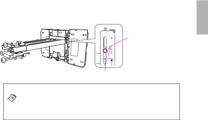
Distance from projection surface to wall plate |
|
|
The distance (c) from the projection surface to the wall plate is the number given when the vertical slide is set |
|
|
to the base position, as shown below. |
English |
|
Match the notch on the wall mount to the position of the stamp on the wall plate. |
||
|
||
Base position |
|
 Stamp on plate
Notch on mount arm
The measurements may differ depending on the location where you place the projector.
When projecting in Tele, the quality of the projected images may decrease.
When using BrightLink 575Wi/585Wi/575Wi+/585Wi+ or PowerLite 575W/585W to project images at a 4:3 aspect ratio, the images are resized automatically and the quality of the projected images may decrease.
13
Installation Measurements in Inches for BrightLink 575Wi/585Wi/575Wi+/585Wi+ and PowerLite 575W/585W
|
Diagonal |
|
|
16:10 WXGA |
|
|
|
|
|
4:3 XGA |
|
|
|
|
16:9 Widescreen |
|
|
|||
|
image size |
Min. |
Image |
Image |
Min. |
Slider |
Distance |
Min. |
Image |
Image |
|
Min. |
Slider |
Distance |
Min. |
Image |
Image |
Min. |
Slider |
Distance |
|
(S) |
|
||||||||||||||||||
|
ceiling |
width |
height |
projection |
scale |
from top of |
ceiling |
width |
height |
|
projection |
scale |
from top of |
ceiling |
width |
height |
projection |
scale |
from top |
|
|
|
|
||||||||||||||||||
|
|
height* |
(w) |
(h) |
distance (a) |
mark |
image to |
height* |
(w) |
(h) |
|
distance (a) |
mark |
image to |
height* |
(w) |
(h) |
distance (a) |
mark |
of image |
|
|
|
|
|
|
(b) |
wall plate |
|
|
|
|
|
(b) |
wall plate |
|
|
|
|
(b) |
to wall |
|
|
|
|
|
|
|
(c) |
|
|
|
|
|
|
(c) |
|
|
|
|
|
plate (c) |
|
53” |
— |
— |
— |
— |
— |
— |
78.7 |
42.4 |
31.8 |
|
2.5 |
5.9 |
6.9 |
— |
— |
— |
— |
— |
— |
|
|
|
|
|
|
|
|
|
|
|
|
|
|
|
|
|
|
|
|
|
|
54” |
— |
— |
— |
— |
— |
— |
79.4 |
43.2 |
32.4 |
|
2.7 |
6.1 |
7.0 |
— |
— |
— |
— |
— |
— |
|
|
|
|
|
|
|
|
|
|
|
|
|
|
|
|
|
|
|
|
|
|
55” |
— |
— |
— |
— |
— |
— |
80.1 |
44.0 |
33.0 |
|
3.0 |
6.4 |
7.1 |
— |
— |
— |
— |
— |
— |
|
|
|
|
|
|
|
|
|
|
|
|
|
|
|
|
|
|
|
|
|
|
56” |
— |
— |
— |
— |
— |
— |
80.8 |
44.8 |
33.6 |
|
3.3 |
6.7 |
7.2 |
— |
— |
— |
— |
— |
— |
|
|
|
|
|
|
|
|
|
|
|
|
|
|
|
|
|
|
|
|
|
|
57” |
— |
— |
— |
— |
— |
— |
81.5 |
45.6 |
34.2 |
|
3.6 |
7.0 |
7.3 |
— |
— |
— |
— |
— |
— |
|
|
|
|
|
|
|
|
|
|
|
|
|
|
|
|
|
|
|
|
|
|
58” |
— |
— |
— |
— |
— |
— |
82.3 |
46.4 |
34.8 |
|
3.8 |
7.3 |
7.5 |
— |
— |
— |
— |
— |
— |
|
|
|
|
|
|
|
|
|
|
|
|
|
|
|
|
|
|
|
|
|
|
59” |
— |
— |
— |
— |
— |
— |
83.0 |
47.2 |
35.4 |
|
4.1 |
7.6 |
7.6 |
77.5 |
51.4 |
28.9 |
2.6 |
6.0 |
8.5 |
|
|
|
|
|
|
|
|
|
|
|
|
|
|
|
|
|
|
|
|
|
|
60” |
78.7 |
50.9 |
31.8 |
2.5 |
5.9 |
6.9 |
83.7 |
48.0 |
36.0 |
|
4.4 |
7.8 |
7.7 |
78.1 |
52.3 |
29.4 |
2.9 |
6.3 |
8.7 |
|
|
|
|
|
|
|
|
|
|
|
|
|
|
|
|
|
|
|
|
|
14 |
61” |
79.3 |
51.7 |
32.3 |
2.7 |
6.1 |
7.0 |
84.4 |
48.8 |
36.6 |
|
4.7 |
8.1 |
7.8 |
78.7 |
53.2 |
29.9 |
3.1 |
6.5 |
8.8 |
|
|
|
|
|
|
|
|
|
|
|
|
|
|
|
|
|
|
|
|
|
62” |
79.9 |
52.6 |
32.9 |
3.0 |
6.4 |
7.1 |
85.1 |
49.6 |
37.2 |
|
5.0 |
8.4 |
7.9 |
79.3 |
54.0 |
30.4 |
3.4 |
6.8 |
8.9 |
|
|
|
|||||||||||||||||||
|
|
|
|
|
|
|
|
|
|
|
|
|
|
|
|
|
|
|
|
|
|
63” |
80.6 |
53.4 |
33.4 |
3.2 |
6.6 |
7.2 |
85.8 |
50.4 |
37.8 |
|
5.2 |
8.7 |
8.0 |
80.0 |
54.9 |
30.9 |
3.6 |
7.0 |
9.1 |
|
|
|
|
|
|
|
|
|
|
|
|
|
|
|
|
|
|
|
|
|
|
64” |
81.2 |
54.3 |
33.9 |
3.4 |
6.9 |
7.3 |
86.6 |
51.2 |
38.4 |
|
5.5 |
8.9 |
8.2 |
80.6 |
55.8 |
31.4 |
3.9 |
7.3 |
9.2 |
|
|
|
|
|
|
|
|
|
|
|
|
|
|
|
|
|
|
|
|
|
|
65” |
81.8 |
55.1 |
34.4 |
3.7 |
7.1 |
7.4 |
87.3 |
52.0 |
39.0 |
|
5.8 |
9.2 |
8.3 |
81.2 |
56.7 |
31.9 |
4.1 |
7.6 |
9.3 |
|
|
|
|
|
|
|
|
|
|
|
|
|
|
|
|
|
|
|
|
|
|
66” |
82.5 |
56.0 |
35.0 |
3.9 |
7.4 |
7.5 |
88.0 |
52.8 |
39.6 |
|
6.1 |
9.5 |
8.4 |
81.8 |
57.5 |
32.4 |
4.4 |
7.8 |
9.5 |
|
|
|
|
|
|
|
|
|
|
|
|
|
|
|
|
|
|
|
|
|
|
67” |
83.1 |
56.8 |
35.5 |
4.2 |
7.6 |
7.6 |
88.7 |
53.6 |
40.2 |
|
6.3 |
9.8 |
8.5 |
82.5 |
58.4 |
32.9 |
4.6 |
8.0 |
9.6 |
|
|
|
|
|
|
|
|
|
|
|
|
|
|
|
|
|
|
|
|
|
|
68” |
83.7 |
57.7 |
36.0 |
4.4 |
7.8 |
7.7 |
89.4 |
54.4 |
40.8 |
|
6.6 |
10.0 |
8.6 |
83.1 |
59.3 |
33.3 |
4.9 |
8.3 |
9.7 |
|
|
|
|
|
|
|
|
|
|
|
|
|
|
|
|
|
|
|
|
|
|
69” |
84.4 |
58.5 |
36.6 |
4.7 |
8.1 |
7.8 |
90.2 |
55.2 |
41.4 |
|
6.9 |
10.3 |
8.8 |
83.7 |
60.1 |
33.8 |
5.1 |
8.5 |
9.9 |
|
|
|
|
|
|
|
|
|
|
|
|
|
|
|
|
|
|
|
|
|
|
70” |
85.0 |
59.4 |
37.1 |
4.9 |
8.3 |
7.9 |
90.9 |
56.0 |
42.0 |
|
7.2 |
10.6 |
8.9 |
84.3 |
61.0 |
34.3 |
5.4 |
8.8 |
10.0 |
|
|
|
|
|
|
|
|
|
|
|
|
|
|
|
|
|
|
|
|
|
|
71” |
85.6 |
60.2 |
37.6 |
5.1 |
8.6 |
8.0 |
91.6 |
56.8 |
42.6 |
|
7.4 |
10.9 |
9.0 |
85.0 |
61.9 |
34.8 |
5.6 |
9.1 |
10.2 |
|
|
|
|
|
|
|
|
|
|
|
|
|
|
|
|
|
|
|
|
|
|
72” |
86.3 |
61.1 |
38.2 |
5.4 |
8.8 |
8.1 |
92.3 |
57.6 |
43.2 |
|
7.7 |
11.1 |
9.1 |
85.6 |
62.8 |
35.3 |
5.9 |
9.3 |
10.3 |
|
|
|
|
|
|
|
|
|
|
|
|
|
|
|
|
|
|
|
|
|
|
73” |
86.9 |
61.9 |
38.7 |
5.6 |
9.1 |
8.2 |
93.0 |
58.4 |
43.8 |
|
8.0 |
11.4 |
9.2 |
86.2 |
63.6 |
35.8 |
6.1 |
9.6 |
10.4 |
|
|
|
|
|
|
|
|
|
|
|
|
|
|
|
|
|
|
|
|
|
|
74” |
87.5 |
62.8 |
39.2 |
5.9 |
9.3 |
8.3 |
93.8 |
59.2 |
44.4 |
|
8.3 |
11.7 |
9.4 |
86.8 |
64.5 |
36.3 |
6.4 |
9.8 |
10.6 |
|
|
|
|
|
|
|
|
|
|
|
|
|
|
|
|
|
|
|
|
|
|
75” |
88.2 |
63.6 |
39.7 |
6.1 |
6.1 |
8.4 |
94.5 |
60.0 |
45.0 |
|
8.5 |
8.5 |
9.5 |
87.5 |
65.4 |
36.8 |
6.6 |
6.6 |
10.7 |
|
|
|
|
|
|
|
|
|
|
|
|
|
|
|
|
|
|
|
|
|
|
76” |
88.8 |
64.4 |
40.3 |
6.4 |
6.4 |
8.5 |
95.2 |
60.8 |
45.6 |
|
8.8 |
8.8 |
9.6 |
88.1 |
66.2 |
37.3 |
6.9 |
6.9 |
10.8 |
|
|
|
|
|
|
|
|
|
|
|
|
|
|
|
|
|
|
|
|
|

|
Diagonal |
|
|
16:10 WXGA |
|
|
|
|
|
4:3 XGA |
|
|
|
|
16:9 Widescreen |
|
|
|||
|
image size |
Min. |
Image |
Image |
Min. |
Slider |
Distance |
Min. |
Image |
Image |
|
Min. |
Slider |
Distance |
Min. |
Image |
Image |
Min. |
Slider |
Distance |
|
(S) |
|
||||||||||||||||||
|
ceiling |
width |
height |
projection |
scale |
from top of |
ceiling |
width |
height |
|
projection |
scale |
from top of |
ceiling |
width |
height |
projection |
scale |
from top |
|
|
|
|
||||||||||||||||||
|
|
height* |
(w) |
(h) |
distance (a) |
mark |
image to |
height* |
(w) |
(h) |
|
distance (a) |
mark |
image to |
height* |
(w) |
(h) |
distance (a) |
mark |
of image |
|
|
|
|
|
|
(b) |
wall plate |
|
|
|
|
|
(b) |
wall plate |
|
|
|
|
(b) |
to wall |
|
|
|
|
|
|
|
(c) |
|
|
|
|
|
|
(c) |
|
|
|
|
|
plate (c) |
|
77” |
89.5 |
65.3 |
40.8 |
6.6 |
6.6 |
8.6 |
95.9 |
61.6 |
46.2 |
|
9.1 |
9.1 |
9.7 |
88.7 |
67.1 |
37.8 |
7.1 |
7.1 |
11.0 |
|
|
|
|
|
|
|
|
|
|
|
|
|
|
|
|
|
|
|
|
|
|
78” |
90.1 |
66.1 |
41.3 |
6.9 |
6.9 |
8.8 |
96.6 |
62.4 |
46.8 |
|
9.4 |
9.4 |
9.8 |
89.3 |
68.0 |
38.2 |
7.4 |
7.4 |
11.1 |
|
|
|
|
|
|
|
|
|
|
|
|
|
|
|
|
|
|
|
|
|
|
79” |
90.7 |
67.0 |
41.9 |
7.1 |
7.1 |
8.9 |
97.4 |
63.2 |
47.4 |
|
9.7 |
9.7 |
10.0 |
90.0 |
68.9 |
38.7 |
7.6 |
7.6 |
11.2 |
|
|
|
|
|
|
|
|
|
|
|
|
|
|
|
|
|
|
|
|
|
|
80” |
91.4 |
67.8 |
42.4 |
7.3 |
7.3 |
9.0 |
98.1 |
64.0 |
48.0 |
|
9.9 |
9.9 |
10.1 |
90.6 |
69.7 |
39.2 |
7.9 |
7.9 |
11.4 |
|
|
|
|
|
|
|
|
|
|
|
|
|
|
|
|
|
|
|
|
|
|
81” |
92.0 |
68.7 |
42.9 |
7.6 |
7.6 |
9.1 |
98.8 |
64.8 |
48.6 |
|
10.2 |
10.2 |
10.2 |
91.2 |
70.6 |
39.7 |
8.1 |
8.1 |
11.5 |
|
|
|
|
|
|
|
|
|
|
|
|
|
|
|
|
|
|
|
|
|
|
82” |
92.6 |
69.5 |
43.5 |
7.8 |
7.8 |
9.2 |
99.5 |
65.6 |
49.2 |
|
10.5 |
10.5 |
10.3 |
91.8 |
71.5 |
40.2 |
8.4 |
8.4 |
11.6 |
|
|
|
|
|
|
|
|
|
|
|
|
|
|
|
|
|
|
|
|
|
|
83” |
93.3 |
70.4 |
44.0 |
8.1 |
8.1 |
9.3 |
100.2 |
66.4 |
49.8 |
|
10.8 |
10.8 |
10.4 |
92.5 |
72.3 |
40.7 |
8.6 |
8.6 |
11.8 |
|
|
|
|
|
|
|
|
|
|
|
|
|
|
|
|
|
|
|
|
|
|
84” |
93.9 |
71.2 |
44.5 |
8.3 |
8.3 |
9.4 |
100.9 |
67.2 |
50.4 |
|
11.0 |
11.0 |
10.5 |
93.1 |
73.2 |
41.2 |
8.9 |
8.9 |
11.9 |
|
|
|
|
|
|
|
|
|
|
|
|
|
|
|
|
|
|
|
|
|
|
85” |
94.5 |
72.1 |
45.0 |
8.6 |
8.6 |
9.5 |
101.7 |
68.0 |
51.0 |
|
11.3 |
11.3 |
10.7 |
93.7 |
74.1 |
41.7 |
9.1 |
9.1 |
12.0 |
|
|
|
|
|
|
|
|
|
|
|
|
|
|
|
|
|
|
|
|
|
15 |
86” |
95.2 |
72.9 |
45.6 |
8.8 |
8.8 |
9.6 |
102.4 |
68.8 |
51.6 |
|
11.6 |
11.6 |
10.8 |
94.3 |
75.0 |
42.2 |
9.4 |
9.4 |
12.2 |
|
|
|
|
|
|
|
|
|
|
|
|
|
|
|
|
|
|
|
|
|
87” |
95.8 |
73.8 |
46.1 |
9.1 |
9.1 |
9.7 |
103.1 |
69.6 |
52.2 |
|
11.9 |
11.9 |
10.9 |
95.0 |
75.8 |
42.7 |
9.6 |
9.6 |
12.3 |
|
|
|
|
|
|
|
|
|
|
|
|
|
|
|
|
|
|
|
|
|
|
|
88” |
96.4 |
74.6 |
46.6 |
9.3 |
9.3 |
9.8 |
103.8 |
70.4 |
52.8 |
|
12.1 |
12.1 |
11.0 |
95.6 |
76.7 |
43.1 |
9.9 |
9.9 |
12.5 |
|
|
|
|
|
|
|
|
|
|
|
|
|
|
|
|
|
|
|
|
|
|
89” |
97.1 |
75.5 |
47.2 |
9.5 |
9.5 |
9.9 |
— |
— |
— |
|
— |
— |
— |
96.2 |
77.6 |
43.6 |
10.2 |
10.2 |
12.6 |
|
|
|
|
|
|
|
|
|
|
|
|
|
|
|
|
|
|
|
|
|
|
90” |
97.7 |
76.3 |
47.7 |
9.6 |
9.6 |
10.0 |
— |
— |
— |
|
— |
— |
— |
96.8 |
78.4 |
44.1 |
10.4 |
10.4 |
12.7 |
|
|
|
|
|
|
|
|
|
|
|
|
|
|
|
|
|
|
|
|
|
|
91” |
98.3 |
77.2 |
48.2 |
10.0 |
10.0 |
10.1 |
— |
— |
— |
|
— |
— |
— |
97.5 |
79.3 |
44.6 |
10.7 |
10.7 |
12.9 |
|
|
|
|
|
|
|
|
|
|
|
|
|
|
|
|
|
|
|
|
|
|
92” |
99.0 |
78.0 |
48.8 |
10.3 |
10.3 |
10.2 |
— |
— |
— |
|
— |
— |
— |
98.1 |
80.2 |
45.1 |
10.9 |
10.9 |
13.0 |
|
|
|
|
|
|
|
|
|
|
|
|
|
|
|
|
|
|
|
|
|
|
93” |
99.6 |
78.9 |
49.3 |
10.5 |
10.5 |
10.3 |
— |
— |
— |
|
— |
— |
— |
98.7 |
81.1 |
45.6 |
11.2 |
11.2 |
13.1 |
|
|
|
|
|
|
|
|
|
|
|
|
|
|
|
|
|
|
|
|
|
|
94” |
100.3 |
79.7 |
49.8 |
10.8 |
10.8 |
10.4 |
— |
— |
— |
|
— |
— |
— |
99.3 |
81.9 |
46.1 |
11.4 |
11.4 |
13.3 |
|
|
|
|
|
|
|
|
|
|
|
|
|
|
|
|
|
|
|
|
|
|
95” |
100.9 |
80.6 |
50.3 |
11.0 |
11.0 |
10.5 |
— |
— |
— |
|
— |
— |
— |
100.0 |
82.8 |
46.6 |
11.7 |
11.7 |
13.4 |
|
|
|
|
|
|
|
|
|
|
|
|
|
|
|
|
|
|
|
|
|
|
96” |
101.5 |
81.4 |
50.9 |
11.3 |
11.3 |
10.6 |
— |
— |
— |
|
— |
— |
— |
100.6 |
83.7 |
47.1 |
11.9 |
11.9 |
13.5 |
|
|
|
|
|
|
|
|
|
|
|
|
|
|
|
|
|
|
|
|
|
|
97” |
102.2 |
82.3 |
51.4 |
11.5 |
11.5 |
10.7 |
— |
— |
— |
|
— |
— |
— |
101.2 |
84.5 |
47.6 |
12.2 |
12.2 |
13.7 |
|
|
|
|
|
|
|
|
|
|
|
|
|
|
|
|
|
|
|
|
|
|
98” |
102.8 |
83.1 |
51.9 |
11.7 |
11.7 |
10.9 |
— |
— |
— |
|
— |
— |
— |
— |
— |
— |
— |
— |
— |
|
|
|
|
|
|
|
|
|
|
|
|
|
|
|
|
|
|
|
|
|
|
99” |
103.4 |
84.0 |
52.5 |
12.0 |
12.0 |
11.0 |
— |
— |
— |
|
— |
— |
— |
— |
— |
— |
— |
— |
— |
|
|
|
|
|
|
|
|
|
|
|
|
|
|
|
|
|
|
|
|
|
|
100” |
104.1 |
84.8 |
53.0 |
12.2 |
12.2 |
11.1 |
— |
— |
— |
|
— |
— |
— |
— |
— |
— |
— |
— |
— |
|
|
|
|
|
|
|
|
|
|
|
|
|
|
|
|
|
|
|
|
|
* Based on an image 30 inches from the floor; if the image is lower, the minimum ceiling height is reduced by the corresponding measurement.
English
Installation Measurements in Inches for PowerLite 570/580
|
Diagonal |
|
|
4:3 XGA |
|
|
|
|
16:10 WXGA |
|
|
|
|
16:9 Widescreen |
|
|
||||
|
image size |
|
|
|
|
|
|
|
|
|
|
|
|
|
|
|
|
|
|
|
|
Min. |
Image |
Image |
Min. |
Slider |
Distance |
Min. |
Image |
Image |
Min. |
Slider |
Distance |
Min. |
Image |
Image |
Min. |
Slider |
Distance |
||
|
(S) |
|||||||||||||||||||
|
ceiling |
width |
height |
projection |
scale |
from top of |
ceiling |
width |
height |
projection |
scale |
from top |
ceiling |
width |
height |
projection |
scale |
from top |
||
|
|
|||||||||||||||||||
|
|
height* |
(w) |
(h) |
distance (a) |
mark |
image to |
height* |
(w) |
(h) |
distance (a) |
mark |
of image |
height* |
(w) |
(h) |
distance (a) |
mark |
of image |
|
|
|
|
|
|
|
(b) |
wall plate |
|
|
|
|
(b) |
to wall |
|
|
|
|
(b) |
to wall |
|
|
|
|
|
|
|
|
(c) |
|
|
|
|
|
plate (c) |
|
|
|
|
|
plate (c) |
|
|
|
|
|
|
|
|
|
|
|
|
|
|
|
|
|
|
|
|
|
|
|
52” |
— |
— |
— |
— |
— |
— |
— |
— |
— |
— |
— |
— |
75.8 |
45.3 |
25.5 |
2.6 |
6.1 |
10.3 |
|
|
|
|
|
|
|
|
|
|
|
|
|
|
|
|
|
|
|
|
|
|
|
53” |
— |
— |
— |
— |
— |
— |
76.9 |
44.9 |
28.1 |
2.5 |
5.9 |
8.8 |
76.4 |
46.2 |
26.0 |
2.9 |
6.3 |
10.5 |
|
|
|
|
|
|
|
|
|
|
|
|
|
|
|
|
|
|
|
|
|
|
|
54” |
— |
— |
— |
— |
— |
— |
77.6 |
45.8 |
28.6 |
2.8 |
6.2 |
9.0 |
77.1 |
47.1 |
26.5 |
3.2 |
6.6 |
10.7 |
|
|
|
|
|
|
|
|
|
|
|
|
|
|
|
|
|
|
|
|
|
|
|
55” |
— |
— |
— |
— |
— |
— |
78.2 |
46.6 |
29.2 |
3.1 |
6.5 |
9.1 |
77.8 |
47.9 |
27.0 |
3.5 |
6.9 |
10.8 |
|
|
|
|
|
|
|
|
|
|
|
|
|
|
|
|
|
|
|
|
|
|
|
56” |
79.6 |
44.8 |
33.6 |
2.5 |
5.9 |
6.0 |
78.9 |
47.5 |
29.7 |
3.4 |
6.8 |
9.3 |
78.5 |
48.8 |
27.5 |
3.8 |
7.2 |
11.0 |
|
|
|
|
|
|
|
|
|
|
|
|
|
|
|
|
|
|
|
|
|
|
|
57” |
80.3 |
45.6 |
34.2 |
2.7 |
6.1 |
6.1 |
79.6 |
48.3 |
30.2 |
3.6 |
7.0 |
9.4 |
79.2 |
49.7 |
27.9 |
4.1 |
7.5 |
11.2 |
|
|
|
|
|
|
|
|
|
|
|
|
|
|
|
|
|
|
|
|
|
|
|
58” |
80.9 |
46.4 |
34.8 |
3.0 |
6.4 |
6.2 |
80.3 |
49.2 |
30.7 |
3.9 |
7.3 |
9.6 |
79.8 |
50.6 |
28.4 |
4.4 |
7.8 |
11.4 |
|
|
|
|
|
|
|
|
|
|
|
|
|
|
|
|
|
|
|
|
|
|
|
59” |
81.7 |
47.2 |
35.4 |
3.3 |
6.7 |
6.3 |
81.0 |
50.0 |
31.3 |
4.2 |
7.6 |
9.7 |
80.5 |
51.4 |
28.9 |
4.6 |
8.1 |
11.6 |
|
16 |
|
|
|
|
|
|
|
|
|
|
|
|
|
|
|
|
|
|
|
|
60” |
82.3 |
48.0 |
36.0 |
3.5 |
6.9 |
6.4 |
81.7 |
50.9 |
31.8 |
4.5 |
7.9 |
9.9 |
81.2 |
52.3 |
29.4 |
4.9 |
8.3 |
11.8 |
||
|
||||||||||||||||||||
|
|
|
|
|
|
|
|
|
|
|
|
|
|
|
|
|
|
|
|
|
|
61” |
83.1 |
48.8 |
36.6 |
3.8 |
7.2 |
6.5 |
82.4 |
51.7 |
32.3 |
4.7 |
8.1 |
10.0 |
81.9 |
53.2 |
29.9 |
5.2 |
8.6 |
12.0 |
|
|
|
|
|
|
|
|
|
|
|
|
|
|
|
|
|
|
|
|
|
|
|
62” |
83.7 |
49.6 |
37.2 |
4.1 |
7.5 |
6.6 |
83.1 |
52.6 |
32.9 |
5.0 |
8.4 |
10.2 |
82.6 |
54.0 |
30.4 |
5.5 |
8.9 |
12.2 |
|
|
|
|
|
|
|
|
|
|
|
|
|
|
|
|
|
|
|
|
|
|
|
63” |
84.4 |
50.4 |
37.8 |
4.3 |
7.7 |
6.6 |
83.7 |
53.4 |
33.4 |
5.3 |
8.7 |
10.4 |
83.2 |
54.9 |
30.9 |
5.8 |
9.2 |
12.3 |
|
|
|
|
|
|
|
|
|
|
|
|
|
|
|
|
|
|
|
|
|
|
|
64” |
85.1 |
51.2 |
38.4 |
4.6 |
8.0 |
6.7 |
84.4 |
54.3 |
33.9 |
5.6 |
9.0 |
10.5 |
83.9 |
55.8 |
31.4 |
6.1 |
9.5 |
12.5 |
|
|
|
|
|
|
|
|
|
|
|
|
|
|
|
|
|
|
|
|
|
|
|
65” |
85.9 |
52.0 |
39.0 |
4.8 |
8.2 |
6.8 |
85.1 |
55.1 |
34.4 |
5.8 |
9.3 |
10.7 |
84.6 |
56.7 |
31.9 |
6.4 |
9.8 |
12.7 |
|
|
|
|
|
|
|
|
|
|
|
|
|
|
|
|
|
|
|
|
|
|
|
66” |
86.5 |
52.8 |
39.6 |
5.1 |
8.5 |
6.9 |
85.8 |
56.0 |
35.0 |
6.1 |
9.5 |
10.8 |
85.3 |
57.5 |
32.4 |
6.6 |
10.0 |
12.9 |
|
|
|
|
|
|
|
|
|
|
|
|
|
|
|
|
|
|
|
|
|
|
|
67” |
87.2 |
53.6 |
40.2 |
5.4 |
8.8 |
7.0 |
86.5 |
56.8 |
35.5 |
6.4 |
9.8 |
11.0 |
85.9 |
58.4 |
32.9 |
6.9 |
10.4 |
13.1 |
|
|
|
|
|
|
|
|
|
|
|
|
|
|
|
|
|
|
|
|
|
|
|
68” |
87.9 |
54.4 |
40.8 |
5.6 |
9.0 |
7.1 |
87.2 |
57.7 |
36.0 |
6.7 |
10.1 |
11.1 |
86.6 |
59.3 |
33.3 |
7.2 |
10.6 |
13.3 |
|
|
|
|
|
|
|
|
|
|
|
|
|
|
|
|
|
|
|
|
|
|
|
69” |
88.6 |
55.2 |
41.4 |
5.9 |
9.3 |
7.2 |
87.9 |
58.5 |
36.6 |
7.0 |
10.4 |
11.3 |
87.3 |
60.1 |
33.8 |
7.5 |
10.9 |
13.5 |
|
|
|
|
|
|
|
|
|
|
|
|
|
|
|
|
|
|
|
|
|
|
|
70” |
89.3 |
56.0 |
42.0 |
6.1 |
9.6 |
7.3 |
88.5 |
59.4 |
37.1 |
7.2 |
10.7 |
11.4 |
88.0 |
61.0 |
34.3 |
7.8 |
11.2 |
13.7 |
|
|
|
|
|
|
|
|
|
|
|
|
|
|
|
|
|
|
|
|
|
|
|
71” |
90.0 |
56.8 |
42.6 |
6.4 |
9.8 |
7.4 |
89.2 |
60.2 |
37.6 |
7.5 |
10.9 |
11.6 |
88.6 |
61.9 |
34.8 |
8.1 |
11.5 |
13.8 |
|
|
|
|
|
|
|
|
|
|
|
|
|
|
|
|
|
|
|
|
|
|
|
72” |
90.7 |
57.6 |
43.2 |
6.7 |
10.1 |
7.5 |
89.9 |
61.1 |
38.2 |
7.8 |
11.2 |
11.8 |
89.3 |
62.8 |
35.3 |
8.3 |
11.6 |
14.0 |
|
|
|
|
|
|
|
|
|
|
|
|
|
|
|
|
|
|
|
|
|
|
|
73” |
91.4 |
58.4 |
43.8 |
6.9 |
10.4 |
7.6 |
90.6 |
61.9 |
38.7 |
8.1 |
11.5 |
11.9 |
90.0 |
63.6 |
35.8 |
8.6 |
12.0 |
14.2 |
|
|
|
|
|
|
|
|
|
|
|
|
|
|
|
|
|
|
|
|
|
|
|
74” |
92.1 |
59.2 |
44.4 |
7.2 |
10.6 |
7.7 |
91.3 |
62.8 |
39.2 |
8.3 |
11.8 |
12.1 |
90.7 |
64.5 |
36.3 |
8.9 |
12.3 |
14.4 |
|
|
|
|
|
|
|
|
|
|
|
|
|
|
|
|
|
|
|
|
|
|

|
Diagonal |
|
|
4:3 XGA |
|
|
|
|
16:10 WXGA |
|
|
|
|
16:9 Widescreen |
|
|
||||
|
image size |
|
|
|
|
|
|
|
|
|
|
|
|
|
|
|
|
|
|
|
|
Min. |
Image |
Image |
Min. |
Slider |
Distance |
Min. |
Image |
Image |
Min. |
Slider |
Distance |
Min. |
Image |
Image |
Min. |
Slider |
Distance |
||
|
(S) |
|||||||||||||||||||
|
ceiling |
width |
height |
projection |
scale |
from top of |
ceiling |
width |
height |
projection |
scale |
from top |
ceiling |
width |
height |
projection |
scale |
from top |
||
|
|
|||||||||||||||||||
|
|
height* |
(w) |
(h) |
distance (a) |
mark |
image to |
height* |
(w) |
(h) |
distance (a) |
mark |
of image |
height* |
(w) |
(h) |
distance (a) |
mark |
of image |
|
|
|
|
|
|
|
(b) |
wall plate |
|
|
|
|
(b) |
to wall |
|
|
|
|
(b) |
to wall |
|
|
|
|
|
|
|
|
(c) |
|
|
|
|
|
plate (c) |
|
|
|
|
|
plate (c) |
|
|
|
|
|
|
|
|
|
|
|
|
|
|
|
|
|
|
|
|
|
|
|
75” |
92.8 |
60.0 |
45.0 |
7.4 |
7.4 |
7.8 |
92.0 |
63.6 |
39.7 |
8.6 |
8.6 |
12.2 |
91.4 |
65.4 |
36.8 |
9.2 |
9.2 |
14.6 |
|
|
|
|
|
|
|
|
|
|
|
|
|
|
|
|
|
|
|
|
|
|
|
76” |
93.5 |
60.8 |
45.6 |
7.7 |
7.7 |
7.9 |
92.6 |
64.4 |
40.3 |
8.9 |
8.9 |
12.4 |
92.0 |
66.2 |
37.3 |
9.5 |
9.5 |
14.8 |
|
|
|
|
|
|
|
|
|
|
|
|
|
|
|
|
|
|
|
|
|
|
|
77” |
94.2 |
61.6 |
46.2 |
8.0 |
8.0 |
8.0 |
93.3 |
65.3 |
40.8 |
9.2 |
9.2 |
12.5 |
92.7 |
67.1 |
37.8 |
9.8 |
9.8 |
15.0 |
|
|
|
|
|
|
|
|
|
|
|
|
|
|
|
|
|
|
|
|
|
|
|
78” |
94.9 |
62.4 |
46.8 |
8.2 |
8.2 |
8.1 |
94.0 |
66.1 |
41.3 |
9.5 |
9.5 |
12.7 |
93.4 |
68.0 |
38.2 |
10.1 |
10.1 |
15.1 |
|
|
|
|
|
|
|
|
|
|
|
|
|
|
|
|
|
|
|
|
|
|
|
79” |
95.6 |
63.2 |
47.4 |
8.5 |
8.5 |
8.2 |
94.7 |
67.0 |
41.9 |
9.7 |
9.7 |
12.8 |
94.1 |
68.9 |
38.7 |
10.3 |
10.3 |
15.3 |
|
|
|
|
|
|
|
|
|
|
|
|
|
|
|
|
|
|
|
|
|
|
|
80” |
96.3 |
64.0 |
48.0 |
8.8 |
8.8 |
8.3 |
95.4 |
67.8 |
42.4 |
10.0 |
10.0 |
13.0 |
94.7 |
69.7 |
39.2 |
10.6 |
10.6 |
15.5 |
|
|
|
|
|
|
|
|
|
|
|
|
|
|
|
|
|
|
|
|
|
|
|
81” |
97.0 |
64.8 |
48.6 |
9.0 |
9.0 |
8.4 |
96.1 |
68.7 |
42.9 |
10.3 |
10.3 |
13.2 |
95.4 |
70.6 |
39.7 |
10.9 |
10.9 |
15.7 |
|
|
|
|
|
|
|
|
|
|
|
|
|
|
|
|
|
|
|
|
|
|
|
82” |
97.7 |
65.6 |
49.2 |
9.3 |
9.3 |
8.5 |
96.8 |
69.5 |
43.5 |
10.6 |
10.6 |
13.3 |
96.1 |
71.5 |
40.2 |
11.2 |
11.2 |
15.9 |
|
|
|
|
|
|
|
|
|
|
|
|
|
|
|
|
|
|
|
|
|
|
|
83” |
98.4 |
66.4 |
49.8 |
9.5 |
9.5 |
8.6 |
97.4 |
70.4 |
44.0 |
10.8 |
10.8 |
13.5 |
96.8 |
72.3 |
40.7 |
11.5 |
11.5 |
16.1 |
|
17 |
|
|
|
|
|
|
|
|
|
|
|
|
|
|
|
|
|
|
|
|
84” |
99.1 |
67.2 |
50.4 |
9.8 |
9.8 |
8.7 |
98.1 |
71.2 |
44.5 |
11.1 |
11.1 |
13.6 |
97.5 |
73.2 |
41.2 |
11.8 |
11.8 |
16.3 |
||
|
|
|
|
|
|
|
|
|
|
|
|
|
|
|
|
|
|
|
||
85” |
99.8 |
68.0 |
51.0 |
10.1 |
10.1 |
8.8 |
98.8 |
72.1 |
45.0 |
11.4 |
11.4 |
13.8 |
98.1 |
74.1 |
41.7 |
12.1 |
12.1 |
16.5 |
||
|
||||||||||||||||||||
|
|
|
|
|
|
|
|
|
|
|
|
|
|
|
|
|
|
|
|
|
|
86” |
100.5 |
68.8 |
51.6 |
10.3 |
10.3 |
8.9 |
99.5 |
72.9 |
45.6 |
11.7 |
11.7 |
13.9 |
— |
— |
— |
— |
— |
— |
|
|
|
|
|
|
|
|
|
|
|
|
|
|
|
|
|
|
|
|
|
|
|
87” |
101.2 |
69.6 |
52.2 |
10.6 |
10.6 |
9.0 |
100.2 |
73.8 |
46.1 |
12.0 |
12.0 |
14.1 |
— |
— |
— |
— |
— |
— |
|
|
|
|
|
|
|
|
|
|
|
|
|
|
|
|
|
|
|
|
|
|
|
88” |
101.9 |
70.4 |
52.8 |
10.9 |
10.9 |
9.1 |
100.9 |
74.6 |
46.6 |
12.2 |
12.2 |
14.2 |
— |
— |
— |
— |
— |
— |
|
|
|
|
|
|
|
|
|
|
|
|
|
|
|
|
|
|
|
|
|
|
|
89” |
102.6 |
71.2 |
53.4 |
11.1 |
11.1 |
9.2 |
— |
— |
— |
— |
— |
— |
— |
— |
— |
— |
— |
— |
|
|
|
|
|
|
|
|
|
|
|
|
|
|
|
|
|
|
|
|
|
|
|
90” |
103.3 |
72.0 |
54.0 |
11.4 |
11.4 |
9.3 |
— |
— |
— |
— |
— |
— |
— |
— |
— |
— |
— |
— |
|
|
|
|
|
|
|
|
|
|
|
|
|
|
|
|
|
|
|
|
|
|
|
91” |
104.0 |
72.8 |
54.6 |
11.6 |
11.6 |
9.4 |
— |
— |
— |
— |
— |
— |
— |
— |
— |
— |
— |
— |
|
|
|
|
|
|
|
|
|
|
|
|
|
|
|
|
|
|
|
|
|
|
|
92” |
104.6 |
73.6 |
55.2 |
11.9 |
11.9 |
9.5 |
— |
— |
— |
— |
— |
— |
— |
— |
— |
— |
— |
— |
|
|
|
|
|
|
|
|
|
|
|
|
|
|
|
|
|
|
|
|
|
|
|
93” |
105.3 |
74.4 |
55.8 |
12.2 |
12.2 |
9.6 |
— |
— |
— |
— |
— |
— |
— |
— |
— |
— |
— |
— |
|
|
|
|
|
|
|
|
|
|
|
|
|
|
|
|
|
|
|
|
|
|
* Based on an image 30 inches from the floor; if the image is lower, the minimum ceiling height is reduced by the corresponding measurement.
English
Installation Measurements in Millimeters for BrightLink 575Wi/585Wi/575Wi+/585Wi+ and PowerLite 575W/585W
|
Diagonal |
|
|
16:10 WXGA |
|
|
|
|
|
4:3 XGA |
|
|
|
|
16:9 Widescreen |
|
|
|||
|
image size |
Min. |
Image |
Image |
Min. |
Slider |
Distance |
Min. |
Image |
Image |
|
Min. |
Slider |
Distance |
Min. |
Image |
Image |
Min. |
Slider |
Distance |
|
(S) |
|
||||||||||||||||||
|
ceiling |
width |
height |
projection |
scale |
from top |
ceiling |
width |
height |
|
projection |
scale |
from top |
ceiling |
width |
height |
Projection |
scale |
from top |
|
|
|
|
||||||||||||||||||
|
|
height* |
(w) |
(h) |
distance (a) |
mark |
of image |
height* |
(w) |
(h) |
|
distance (a) |
mark |
of image |
height* |
(w) |
(h) |
distance (a) |
mark |
of image |
|
|
|
|
|
|
(b) |
to wall |
|
|
|
|
|
(b) |
to wall |
|
|
|
|
(b) |
to wall |
|
|
|
|
|
|
|
plate (c) |
|
|
|
|
|
|
plate (c) |
|
|
|
|
|
plate (c) |
|
53” |
— |
— |
— |
— |
— |
— |
1998 |
1077 |
808 |
|
62 |
149 |
174 |
— |
— |
— |
— |
— |
— |
|
|
|
|
|
|
|
|
|
|
|
|
|
|
|
|
|
|
|
|
|
|
54” |
— |
— |
— |
— |
— |
— |
2016 |
1097 |
823 |
|
69 |
156 |
177 |
— |
— |
— |
— |
— |
— |
|
|
|
|
|
|
|
|
|
|
|
|
|
|
|
|
|
|
|
|
|
|
55” |
— |
— |
— |
— |
— |
— |
2034 |
1118 |
838 |
|
76 |
163 |
180 |
— |
— |
— |
— |
— |
— |
|
|
|
|
|
|
|
|
|
|
|
|
|
|
|
|
|
|
|
|
|
|
56” |
— |
— |
— |
— |
— |
— |
2052 |
1138 |
853 |
|
83 |
170 |
183 |
— |
— |
— |
— |
— |
— |
|
|
|
|
|
|
|
|
|
|
|
|
|
|
|
|
|
|
|
|
|
|
57” |
— |
— |
— |
— |
— |
— |
2071 |
1158 |
869 |
|
91 |
178 |
186 |
— |
— |
— |
— |
— |
— |
|
|
|
|
|
|
|
|
|
|
|
|
|
|
|
|
|
|
|
|
|
|
58” |
— |
— |
— |
— |
— |
— |
2089 |
1179 |
884 |
|
98 |
185 |
189 |
— |
— |
— |
— |
— |
— |
|
|
|
|
|
|
|
|
|
|
|
|
|
|
|
|
|
|
|
|
|
|
59” |
— |
— |
— |
— |
— |
— |
2107 |
1199 |
899 |
|
105 |
192 |
192 |
1968 |
1306 |
735 |
66 |
153 |
217 |
|
|
|
|
|
|
|
|
|
|
|
|
|
|
|
|
|
|
|
|
|
|
60” |
1998 |
1292 |
808 |
62 |
149 |
174 |
2125 |
1219 |
914 |
|
112 |
199 |
195 |
1983 |
1328 |
747 |
73 |
160 |
220 |
|
|
|
|
|
|
|
|
|
|
|
|
|
|
|
|
|
|
|
|
|
18 |
61” |
2014 |
1314 |
821 |
69 |
156 |
177 |
2144 |
1240 |
930 |
|
119 |
206 |
198 |
1999 |
1350 |
760 |
79 |
166 |
223 |
|
|
|
|
|
|
|
|
|
|
|
|
|
|
|
|
|
|
|
|
|
62” |
2030 |
1335 |
835 |
75 |
162 |
179 |
2162 |
1260 |
945 |
|
126 |
213 |
201 |
2015 |
1373 |
772 |
86 |
173 |
227 |
|
|
|
|||||||||||||||||||
|
|
|
|
|
|
|
|
|
|
|
|
|
|
|
|
|
|
|
|
|
|
63” |
2046 |
1357 |
848 |
81 |
168 |
182 |
2180 |
1280 |
960 |
|
133 |
220 |
204 |
2031 |
1395 |
785 |
92 |
179 |
230 |
|
|
|
|
|
|
|
|
|
|
|
|
|
|
|
|
|
|
|
|
|
|
64” |
2063 |
1379 |
862 |
87 |
174 |
185 |
2198 |
1300 |
975 |
|
140 |
227 |
207 |
2047 |
1417 |
797 |
98 |
185 |
234 |
|
|
|
|
|
|
|
|
|
|
|
|
|
|
|
|
|
|
|
|
|
|
65” |
2078 |
1400 |
875 |
93 |
180 |
187 |
2217 |
1321 |
991 |
|
147 |
234 |
210 |
2062 |
1439 |
809 |
105 |
192 |
237 |
|
|
|
|
|
|
|
|
|
|
|
|
|
|
|
|
|
|
|
|
|
|
66” |
2094 |
1422 |
888 |
100 |
187 |
190 |
2235 |
1341 |
1006 |
|
154 |
241 |
213 |
2079 |
1461 |
822 |
111 |
198 |
241 |
|
|
|
|
|
|
|
|
|
|
|
|
|
|
|
|
|
|
|
|
|
|
67” |
2111 |
1443 |
902 |
106 |
193 |
193 |
2253 |
1361 |
1021 |
|
161 |
248 |
216 |
2094 |
1483 |
834 |
117 |
204 |
244 |
|
|
|
|
|
|
|
|
|
|
|
|
|
|
|
|
|
|
|
|
|
|
68” |
2126 |
1465 |
915 |
112 |
199 |
195 |
2271 |
1382 |
1036 |
|
168 |
256 |
219 |
2111 |
1505 |
847 |
124 |
211 |
248 |
|
|
|
|
|
|
|
|
|
|
|
|
|
|
|
|
|
|
|
|
|
|
69” |
2143 |
1486 |
929 |
118 |
205 |
198 |
2290 |
1402 |
1052 |
|
175 |
262 |
222 |
2126 |
1528 |
859 |
130 |
217 |
251 |
|
|
|
|
|
|
|
|
|
|
|
|
|
|
|
|
|
|
|
|
|
|
70” |
2159 |
1508 |
942 |
124 |
211 |
201 |
2308 |
1422 |
1067 |
|
182 |
269 |
225 |
2142 |
1550 |
872 |
137 |
224 |
254 |
|
|
|
|
|
|
|
|
|
|
|
|
|
|
|
|
|
|
|
|
|
|
71” |
2175 |
1529 |
956 |
131 |
218 |
203 |
2326 |
1443 |
1082 |
|
189 |
276 |
228 |
2158 |
1572 |
884 |
143 |
230 |
258 |
|
|
|
|
|
|
|
|
|
|
|
|
|
|
|
|
|
|
|
|
|
|
72” |
2191 |
1551 |
969 |
137 |
224 |
206 |
2345 |
1463 |
1097 |
|
196 |
283 |
232 |
2174 |
1594 |
897 |
149 |
236 |
261 |
|
|
|
|
|
|
|
|
|
|
|
|
|
|
|
|
|
|
|
|
|
|
73” |
2208 |
1572 |
983 |
143 |
230 |
209 |
2364 |
1483 |
1113 |
|
203 |
290 |
235 |
2190 |
1616 |
909 |
156 |
243 |
265 |
|
|
|
|
|
|
|
|
|
|
|
|
|
|
|
|
|
|
|
|
|
|
74” |
2223 |
1594 |
996 |
149 |
236 |
211 |
2382 |
1504 |
1128 |
|
210 |
297 |
238 |
2205 |
1638 |
921 |
162 |
249 |
268 |
|
|
|
|
|
|
|
|
|
|
|
|
|
|
|
|
|
|
|
|
|
|
75” |
2240 |
1615 |
1010 |
155 |
155 |
214 |
2400 |
1524 |
1143 |
|
217 |
217 |
241 |
2222 |
1660 |
934 |
168 |
168 |
272 |
|
|
|
|
|
|
|
|
|
|
|
|
|
|
|
|
|
|
|
|
|
|
76” |
2256 |
1637 |
1023 |
162 |
162 |
217 |
2418 |
1544 |
1158 |
|
224 |
224 |
244 |
2237 |
1682 |
946 |
175 |
175 |
275 |
|
|
|
|
|
|
|
|
|
|
|
|
|
|
|
|
|
|
|
|
|

|
Diagonal |
|
|
16:10 WXGA |
|
|
|
|
|
4:3 XGA |
|
|
|
|
16:9 Widescreen |
|
|
|||
|
image size |
Min. |
Image |
Image |
Min. |
Slider |
Distance |
Min. |
Image |
Image |
|
Min. |
Slider |
Distance |
Min. |
Image |
Image |
Min. |
Slider |
Distance |
|
(S) |
|
||||||||||||||||||
|
ceiling |
width |
height |
projection |
scale |
from top |
ceiling |
width |
height |
|
projection |
scale |
from top |
ceiling |
width |
height |
Projection |
scale |
from top |
|
|
|
|
||||||||||||||||||
|
|
height* |
(w) |
(h) |
distance (a) |
mark |
of image |
height* |
(w) |
(h) |
|
distance (a) |
mark |
of image |
height* |
(w) |
(h) |
distance (a) |
mark |
of image |
|
|
|
|
|
|
(b) |
to wall |
|
|
|
|
|
(b) |
to wall |
|
|
|
|
(b) |
to wall |
|
|
|
|
|
|
|
plate (c) |
|
|
|
|
|
|
plate (c) |
|
|
|
|
|
plate (c) |
|
77” |
2272 |
1659 |
1037 |
168 |
168 |
219 |
2436 |
1565 |
1173 |
|
231 |
231 |
247 |
2253 |
1705 |
959 |
181 |
181 |
278 |
|
|
|
|
|
|
|
|
|
|
|
|
|
|
|
|
|
|
|
|
|
|
78” |
2288 |
1680 |
1050 |
174 |
174 |
222 |
2455 |
1585 |
1189 |
|
238 |
238 |
250 |
2269 |
1727 |
971 |
188 |
188 |
282 |
|
|
|
|
|
|
|
|
|
|
|
|
|
|
|
|
|
|
|
|
|
|
79” |
2304 |
1702 |
1063 |
180 |
180 |
225 |
2473 |
1605 |
1204 |
|
245 |
245 |
253 |
2285 |
1749 |
984 |
194 |
194 |
285 |
|
|
|
|
|
|
|
|
|
|
|
|
|
|
|
|
|
|
|
|
|
|
80” |
2320 |
1723 |
1077 |
187 |
187 |
227 |
2491 |
1626 |
1219 |
|
252 |
252 |
256 |
2301 |
1771 |
996 |
200 |
200 |
289 |
|
|
|
|
|
|
|
|
|
|
|
|
|
|
|
|
|
|
|
|
|
|
81” |
2336 |
1745 |
1090 |
193 |
193 |
230 |
2509 |
1646 |
1234 |
|
259 |
259 |
259 |
2317 |
1793 |
1009 |
207 |
207 |
292 |
|
|
|
|
|
|
|
|
|
|
|
|
|
|
|
|
|
|
|
|
|
|
82” |
2353 |
1766 |
1104 |
199 |
199 |
233 |
2528 |
1666 |
1250 |
|
266 |
266 |
262 |
2333 |
1815 |
1021 |
213 |
213 |
296 |
|
|
|
|
|
|
|
|
|
|
|
|
|
|
|
|
|
|
|
|
|
|
83” |
2368 |
1788 |
1117 |
205 |
205 |
235 |
2546 |
1687 |
1265 |
|
273 |
273 |
265 |
2349 |
1837 |
1034 |
219 |
219 |
299 |
|
|
|
|
|
|
|
|
|
|
|
|
|
|
|
|
|
|
|
|
|
|
84” |
2385 |
1809 |
1131 |
211 |
211 |
238 |
2564 |
1707 |
1280 |
|
280 |
280 |
268 |
2365 |
1860 |
1046 |
226 |
226 |
303 |
|
|
|
|
|
|
|
|
|
|
|
|
|
|
|
|
|
|
|
|
|
|
85” |
2401 |
1831 |
1144 |
218 |
218 |
241 |
2582 |
1727 |
1295 |
|
287 |
287 |
271 |
2380 |
1882 |
1058 |
232 |
232 |
306 |
|
|
|
|
|
|
|
|
|
|
|
|
|
|
|
|
|
|
|
|
|
19 |
86” |
2417 |
1852 |
1158 |
224 |
224 |
243 |
2601 |
1748 |
1311 |
|
294 |
294 |
274 |
2396 |
1904 |
1071 |
239 |
239 |
309 |
|
|
|
|
|
|
|
|
|
|
|
|
|
|
|
|
|
|
|
|
|
87” |
2433 |
1874 |
1171 |
230 |
230 |
246 |
2619 |
1768 |
1326 |
|
301 |
301 |
277 |
2412 |
1926 |
1083 |
245 |
245 |
313 |
|
|
|
|
|
|
|
|
|
|
|
|
|
|
|
|
|
|
|
|
|
|
|
88” |
2450 |
1895 |
1185 |
236 |
236 |
249 |
2637 |
1788 |
1341 |
|
308 |
308 |
280 |
2428 |
1948 |
1096 |
251 |
251 |
316 |
|
|
|
|
|
|
|
|
|
|
|
|
|
|
|
|
|
|
|
|
|
|
89” |
2466 |
1917 |
1198 |
242 |
242 |
252 |
— |
— |
— |
|
— |
— |
— |
2444 |
1970 |
1108 |
258 |
258 |
320 |
|
|
|
|
|
|
|
|
|
|
|
|
|
|
|
|
|
|
|
|
|
|
90” |
2482 |
1939 |
1212 |
249 |
249 |
254 |
— |
— |
— |
|
— |
— |
— |
2460 |
1992 |
1121 |
264 |
264 |
323 |
|
|
|
|
|
|
|
|
|
|
|
|
|
|
|
|
|
|
|
|
|
|
91” |
2498 |
1960 |
1225 |
255 |
255 |
257 |
— |
— |
— |
|
— |
— |
— |
2476 |
2015 |
1133 |
270 |
270 |
327 |
|
|
|
|
|
|
|
|
|
|
|
|
|
|
|
|
|
|
|
|
|
|
92” |
2515 |
1982 |
1239 |
261 |
261 |
260 |
— |
— |
— |
|
— |
— |
— |
2492 |
2037 |
1146 |
277 |
277 |
330 |
|
|
|
|
|
|
|
|
|
|
|
|
|
|
|
|
|
|
|
|
|
|
93” |
2530 |
2003 |
1252 |
267 |
267 |
262 |
— |
— |
— |
|
— |
— |
— |
2507 |
2059 |
1158 |
283 |
283 |
333 |
|
|
|
|
|
|
|
|
|
|
|
|
|
|
|
|
|
|
|
|
|
|
94” |
2546 |
2025 |
1265 |
273 |
273 |
265 |
— |
— |
— |
|
— |
— |
— |
2524 |
2081 |
1171 |
290 |
290 |
337 |
|
|
|
|
|
|
|
|
|
|
|
|
|
|
|
|
|
|
|
|
|
|
95” |
2563 |
2046 |
1279 |
280 |
280 |
268 |
— |
— |
— |
|
— |
— |
— |
2539 |
2103 |
1183 |
296 |
296 |
340 |
|
|
|
|
|
|
|
|
|
|
|
|
|
|
|
|
|
|
|
|
|
|
96” |
2578 |
2068 |
1292 |
286 |
286 |
270 |
— |
— |
— |
|
— |
— |
— |
2555 |
2125 |
1195 |
302 |
302 |
344 |
|
|
|
|
|
|
|
|
|
|
|
|
|
|
|
|
|
|
|
|
|
|
97” |
2595 |
2089 |
1306 |
292 |
292 |
273 |
— |
— |
— |
|
— |
— |
— |
2571 |
2147 |
1208 |
309 |
309 |
347 |
|
|
|
|
|
|
|
|
|
|
|
|
|
|
|
|
|
|
|
|
|
|
98” |
2611 |
2111 |
1319 |
298 |
298 |
276 |
— |
— |
— |
|
— |
— |
— |
— |
— |
— |
— |
— |
— |
|
|
|
|
|
|
|
|
|
|
|
|
|
|
|
|
|
|
|
|
|
|
99” |
2627 |
2132 |
1333 |
304 |
304 |
278 |
— |
— |
— |
|
— |
— |
— |
— |
— |
— |
— |
— |
— |
|
|
|
|
|
|
|
|
|
|
|
|
|
|
|
|
|
|
|
|
|
|
100” |
2643 |
2154 |
1346 |
311 |
311 |
281 |
— |
— |
— |
|
— |
— |
— |
— |
— |
— |
— |
— |
— |
|
|
|
|
|
|
|
|
|
|
|
|
|
|
|
|
|
|
|
|
|
* Based on an image 762 mm from the floor; if the image is lower, the minimum ceiling height is reduced by the corresponding measurement.
English
Installation Measurements in Millimeters for PowerLite 570/580
|
Diagonal |
|
|
|
4:3 XGA |
|
|
|
|
16:10 WXGA |
|
|
|
|
16:9 Widescreen |
|
|
|||
|
image size |
|
|
|
|
|
|
|
|
|
|
|
|
|
|
|
|
|
|
|
|
Min. |
Image |
Image |
|
Min. |
Slider |
Distance |
Min. |
Image |
Image |
Min. |
Slider |
Distance |
Min. |
Image |
Image |
Min. |
Slider |
Distance |
|
|
(S) |
|
||||||||||||||||||
|
ceiling |
width |
height |
|
projection |
scale |
from top |
ceiling |
width |
height |
projection |
scale |
from top of |
ceiling |
width |
height |
Projection |
scale |
from top |
|
|
|
|
||||||||||||||||||
|
|
height* |
(w) |
(h) |
|
distance (a) |
mark |
of image |
height* |
(w) |
(h) |
distance (a) |
mark |
image to |
height* |
(w) |
(h) |
distance (a) |
mark |
of image |
|
|
|
|
|
|
|
(b) |
to wall |
|
|
|
|
(b) |
wall plate |
|
|
|
|
(b) |
to wall |
|
|
|
|
|
|
|
|
plate (c) |
|
|
|
|
|
(c) |
|
|
|
|
|
plate (c) |
|
|
|
|
|
|
|
|
|
|
|
|
|
|
|
|
|
|
|
|
|
|
52” |
— |
— |
— |
|
— |
— |
— |
— |
— |
— |
— |
— |
— |
1925 |
1151 |
648 |
67 |
154 |
261 |
|
|
|
|
|
|
|
|
|
|
|
|
|
|
|
|
|
|
|
|
|
|
53” |
— |
— |
— |
|
— |
— |
— |
1952 |
1142 |
713 |
64 |
151 |
223 |
1942 |
1173 |
660 |
74 |
161 |
266 |
|
|
|
|
|
|
|
|
|
|
|
|
|
|
|
|
|
|
|
|
|
|
54” |
— |
— |
— |
|
— |
— |
— |
1970 |
1163 |
727 |
71 |
158 |
227 |
1959 |
1195 |
672 |
81 |
168 |
271 |
|
|
|
|
|
|
|
|
|
|
|
|
|
|
|
|
|
|
|
|
|
|
55” |
— |
— |
— |
|
— |
— |
— |
1987 |
1185 |
740 |
78 |
165 |
231 |
1976 |
1218 |
685 |
89 |
176 |
275 |
|
|
|
|
|
|
|
|
|
|
|
|
|
|
|
|
|
|
|
|
|
|
56” |
2021 |
1138 |
853 |
|
63 |
150 |
152 |
2005 |
1206 |
754 |
85 |
172 |
235 |
1993 |
1240 |
697 |
96 |
183 |
280 |
|
|
|
|
|
|
|
|
|
|
|
|
|
|
|
|
|
|
|
|
|
|
57” |
2039 |
1158 |
869 |
|
69 |
156 |
154 |
2022 |
1228 |
767 |
92 |
179 |
239 |
2011 |
1262 |
710 |
103 |
190 |
285 |
|
|
|
|
|
|
|
|
|
|
|
|
|
|
|
|
|
|
|
|
|
|
58” |
2056 |
1179 |
884 |
|
76 |
163 |
156 |
2040 |
1249 |
781 |
99 |
186 |
243 |
2028 |
1284 |
722 |
110 |
197 |
290 |
|
|
|
|
|
|
|
|
|
|
|
|
|
|
|
|
|
|
|
|
|
|
59” |
2074 |
1199 |
899 |
|
83 |
170 |
159 |
2057 |
1271 |
794 |
106 |
193 |
247 |
2045 |
1306 |
735 |
118 |
205 |
294 |
20 |
|
|
|
|
|
|
|
|
|
|
|
|
|
|
|
|
|
|
|
|
60” |
2091 |
1219 |
914 |
|
89 |
176 |
161 |
2075 |
1292 |
808 |
113 |
200 |
251 |
2062 |
1328 |
747 |
125 |
212 |
299 |
|
|
|
|||||||||||||||||||
|
|
|
|
|
|
|
|
|
|
|
|
|
|
|
|
|
|
|
|
|
|
61” |
2110 |
1240 |
930 |
|
96 |
183 |
164 |
2092 |
1314 |
821 |
120 |
207 |
255 |
2080 |
1350 |
760 |
132 |
219 |
304 |
|
|
|
|
|
|
|
|
|
|
|
|
|
|
|
|
|
|
|
|
|
|
62” |
2127 |
1260 |
945 |
|
103 |
190 |
166 |
2110 |
1335 |
835 |
127 |
214 |
259 |
2097 |
1373 |
772 |
139 |
226 |
309 |
|
|
|
|
|
|
|
|
|
|
|
|
|
|
|
|
|
|
|
|
|
|
63” |
2145 |
1280 |
960 |
|
109 |
196 |
169 |
2127 |
1357 |
848 |
134 |
221 |
263 |
2114 |
1395 |
785 |
147 |
234 |
313 |
|
|
|
|
|
|
|
|
|
|
|
|
|
|
|
|
|
|
|
|
|
|
64” |
2162 |
1300 |
975 |
|
116 |
203 |
171 |
2145 |
1379 |
862 |
141 |
228 |
267 |
2131 |
1417 |
797 |
154 |
241 |
318 |
|
|
|
|
|
|
|
|
|
|
|
|
|
|
|
|
|
|
|
|
|
|
65” |
2181 |
1321 |
991 |
|
122 |
209 |
174 |
2162 |
1400 |
875 |
148 |
235 |
271 |
2148 |
1439 |
809 |
161 |
248 |
323 |
|
|
|
|
|
|
|
|
|
|
|
|
|
|
|
|
|
|
|
|
|
|
66” |
2198 |
1341 |
1006 |
|
129 |
216 |
176 |
2179 |
1422 |
888 |
155 |
242 |
275 |
2166 |
1461 |
822 |
168 |
255 |
328 |
|
|
|
|
|
|
|
|
|
|
|
|
|
|
|
|
|
|
|
|
|
|
67” |
2216 |
1361 |
1021 |
|
136 |
223 |
179 |
2197 |
1443 |
902 |
163 |
250 |
279 |
2182 |
1483 |
834 |
176 |
263 |
332 |
|
|
|
|
|
|
|
|
|
|
|
|
|
|
|
|
|
|
|
|
|
|
68” |
2233 |
1382 |
1036 |
|
142 |
229 |
181 |
2214 |
1465 |
915 |
170 |
257 |
283 |
2200 |
1505 |
847 |
183 |
270 |
337 |
|
|
|
|
|
|
|
|
|
|
|
|
|
|
|
|
|
|
|
|
|
|
69” |
2251 |
1402 |
1052 |
|
149 |
236 |
183 |
2232 |
1486 |
929 |
177 |
264 |
287 |
2217 |
1528 |
859 |
190 |
277 |
342 |
|
|
|
|
|
|
|
|
|
|
|
|
|
|
|
|
|
|
|
|
|
|
70” |
2269 |
1422 |
1067 |
|
156 |
243 |
186 |
2249 |
1508 |
942 |
184 |
271 |
291 |
2235 |
1550 |
872 |
197 |
284 |
347 |
|
|
|
|
|
|
|
|
|
|
|
|
|
|
|
|
|
|
|
|
|
|
71” |
2286 |
1443 |
1082 |
|
162 |
249 |
188 |
2266 |
1529 |
956 |
191 |
278 |
294 |
2251 |
1572 |
884 |
205 |
292 |
351 |
|
|
|
|
|
|
|
|
|
|
|
|
|
|
|
|
|
|
|
|
|
|
72” |
2304 |
1463 |
1097 |
|
169 |
256 |
191 |
2283 |
1551 |
969 |
198 |
285 |
298 |
2269 |
1594 |
897 |
212 |
294 |
356 |
|
|
|
|
|
|
|
|
|
|
|
|
|
|
|
|
|
|
|
|
|
|
73” |
2322 |
1483 |
1113 |
|
176 |
263 |
193 |
2301 |
1572 |
983 |
205 |
292 |
302 |
2286 |
1616 |
909 |
219 |
306 |
361 |
|
|
|
|
|
|
|
|
|
|
|
|
|
|
|
|
|
|
|
|
|
|
74” |
2340 |
1504 |
1128 |
|
182 |
269 |
196 |
2318 |
1594 |
996 |
212 |
299 |
306 |
2303 |
1638 |
921 |
226 |
313 |
366 |
|
|
|
|
|
|
|
|
|
|
|
|
|
|
|
|
|
|
|
|
|
|
Diagonal |
|
|
|
4:3 XGA |
|
|
|
|
16:10 WXGA |
|
|
|
|
16:9 Widescreen |
|
|
|||
|
image size |
|
|
|
|
|
|
|
|
|
|
|
|
|
|
|
|
|
|
|
|
Min. |
Image |
Image |
Min. |
Slider |
Distance |
Min. |
Image |
Image |
Min. |
Slider |
Distance |
Min. |
Image |
Image |
Min. |
Slider |
Distance |
||
|
(S) |
|||||||||||||||||||
|
ceiling |
width |
height |
projection |
scale |
from top |
ceiling |
width |
height |
projection |
scale |
from top of |
ceiling |
width |
height |
Projection |
scale |
from top |
||
|
|
|||||||||||||||||||
|
|
height* |
(w) |
(h) |
distance (a) |
mark |
of image |
height* |
(w) |
(h) |
distance (a) |
mark |
image to |
height* |
(w) |
(h) |
distance (a) |
mark |
of image |
|
|
|
|
|
|
|
(b) |
to wall |
|
|
|
|
(b) |
wall plate |
|
|
|
|
(b) |
to wall |
|
|
|
|
|
|
|
|
plate (c) |
|
|
|
|
|
(c) |
|
|
|
|
|
plate (c) |
|
|
|
|
|
|
|
|
|
|
|
|
|
|
|
|
|
|
|
|
|
|
|
75” |
2357 |
1524 |
1143 |
189 |
189 |
198 |
2336 |
1615 |
1010 |
219 |
219 |
310 |
2320 |
1660 |
934 |
234 |
234 |
370 |
|
|
|
|
|
|
|
|
|
|
|
|
|
|
|
|
|
|
|
|
|
|
|
76” |
2375 |
1544 |
1158 |
196 |
196 |
201 |
2353 |
1637 |
1023 |
226 |
226 |
314 |
2337 |
1682 |
946 |
241 |
241 |
375 |
|
|
|
|
|
|
|
|
|
|
|
|
|
|
|
|
|
|
|
|
|
|
|
77” |
2392 |
1565 |
1173 |
202 |
202 |
203 |
2371 |
1659 |
1037 |
233 |
233 |
318 |
2355 |
1705 |
959 |
248 |
248 |
380 |
|
|
|
|
|
|
|
|
|
|
|
|
|
|
|
|
|
|
|
|
|
|
|
78” |
2411 |
1585 |
1189 |
209 |
209 |
206 |
2388 |
1680 |
1050 |
240 |
240 |
322 |
2372 |
1727 |
971 |
255 |
255 |
385 |
|
|
|
|
|
|
|
|
|
|
|
|
|
|
|
|
|
|
|
|
|
|
|
79” |
2428 |
1605 |
1204 |
216 |
216 |
208 |
2405 |
1702 |
1063 |
247 |
247 |
326 |
2389 |
1749 |
984 |
263 |
263 |
389 |
|
|
|
|
|
|
|
|
|
|
|
|
|
|
|
|
|
|
|
|
|
|
|
80” |
2446 |
1626 |
1219 |
222 |
222 |
211 |
2423 |
1723 |
1077 |
254 |
254 |
330 |
2406 |
1771 |
996 |
270 |
270 |
394 |
|
|
|
|
|
|
|
|
|
|
|
|
|
|
|
|
|
|
|
|
|
|
|
81” |
2463 |
1646 |
1234 |
229 |
229 |
213 |
2440 |
1745 |
1090 |
261 |
261 |
334 |
2424 |
1793 |
1009 |
277 |
277 |
399 |
|
|
|
|
|
|
|
|
|
|
|
|
|
|
|
|
|
|
|
|
|
|
|
82” |
2481 |
1666 |
1250 |
236 |
236 |
215 |
2458 |
1766 |
1104 |
268 |
268 |
338 |
2441 |
1815 |
1021 |
284 |
284 |
404 |
|
|
|
|
|
|
|
|
|
|
|
|
|
|
|
|
|
|
|
|
|
|
|
83” |
2499 |
1687 |
1265 |
242 |
242 |
218 |
2475 |
1788 |
1117 |
275 |
275 |
342 |
2458 |
1837 |
1034 |
292 |
292 |
408 |
|
21 |
|
|
|
|
|
|
|
|
|
|
|
|
|
|
|
|
|
|
|
|
84” |
2516 |
1707 |
1280 |
249 |
249 |
220 |
2493 |
1809 |
1131 |
282 |
282 |
346 |
2475 |
1860 |
1046 |
299 |
299 |
413 |
||
|
|
|
|
|
|
|
|
|
|
|
|
|
|
|
|
|
|
|
||
85” |
2534 |
1727 |
1295 |
256 |
256 |
223 |
2510 |
1831 |
1144 |
289 |
289 |
350 |
2492 |
1882 |
1058 |
306 |
306 |
418 |
||
|
||||||||||||||||||||
|
|
|
|
|
|
|
|
|
|
|
|
|
|
|
|
|
|
|
|
|
|
86” |
2552 |
1748 |
1311 |
262 |
262 |
225 |
2528 |
1852 |
1158 |
297 |
297 |
354 |
— |
— |
— |
— |
— |
— |
|
|
|
|
|
|
|
|
|
|
|
|
|
|
|
|
|
|
|
|
|
|
|
87” |
2570 |
1768 |
1326 |
269 |
269 |
228 |
2545 |
1874 |
1171 |
304 |
304 |
358 |
— |
— |
— |
— |
— |
— |
|
|
|
|
|
|
|
|
|
|
|
|
|
|
|
|
|
|
|
|
|
|
|
88” |
2587 |
1788 |
1341 |
275 |
275 |
230 |
2563 |
1895 |
1185 |
311 |
311 |
362 |
— |
— |
— |
— |
— |
— |
|
|
|
|
|
|
|
|
|
|
|
|
|
|
|
|
|
|
|
|
|
|
|
89” |
2605 |
1808 |
1356 |
282 |
282 |
233 |
— |
— |
— |
— |
— |
— |
— |
— |
— |
— |
— |
— |
|
|
|
|
|
|
|
|
|
|
|
|
|
|
|
|
|
|
|
|
|
|
|
90” |
2623 |
1829 |
1372 |
289 |
289 |
235 |
— |
— |
— |
— |
— |
— |
— |
— |
— |
— |
— |
— |
|
|
|
|
|
|
|
|
|
|
|
|
|
|
|
|
|
|
|
|
|
|
|
91” |
2641 |
1849 |
1387 |
295 |
295 |
238 |
— |
— |
— |
— |
— |
— |
— |
— |
— |
— |
— |
— |
|
|
|
|
|
|
|
|
|
|
|
|
|
|
|
|
|
|
|
|
|
|
|
92” |
2658 |
1869 |
1402 |
302 |
302 |
240 |
— |
— |
— |
— |
— |
— |
— |
— |
— |
— |
— |
— |
|
|
|
|
|
|
|
|
|
|
|
|
|
|
|
|
|
|
|
|
|
|
|
93” |
2675 |
1890 |
1417 |
309 |
309 |
242 |
— |
— |
— |
— |
— |
— |
— |
— |
— |
— |
— |
— |
|
|
|
|
|
|
|
|
|
|
|
|
|
|
|
|
|
|
|
|
|
|
* Based on an image 762 mm from the floor; if the image is lower, the minimum ceiling height is reduced by the corresponding measurement.
English
If you have a pre-existing interactive whiteboard, refer to the table below to identify common models and sizes. If your board is listed here, use the dimensions to reference the installation requirements found on pages 14 to 21.
Interactive whiteboard sizes
Diagonal size |
16:10 WXGA |
4:3 XGA |
16:9 Widescreen |
|
|
|
|
57 inches |
— |
PolyVision TS410 |
— |
|
|
|
|
60 inches |
— |
Hitachi® Cambridge board 60 |
— |
|
|
RM ClassBoard2 60 |
|
|
|
INTERWRITE BOARD 1060 |
|
|
|
INTERWRITE Dual board 1260 |
|
|
|
|
|
63 inches |
— |
Hitachi® StarBoard FX-63 |
— |
|
|
|
|
64 inches |
— |
SMART Board 660 |
— |
|
|
Promethean ActivBoard 164 |
|
|
|
|
|
66 inches |
— |
TeamBoard RT TMWM5422CL/EM |
— |
|
|
|
|
71 inches |
— |
— |
INTERWRITE BOARD 1071 |
|
|
|
|
75 inches |
PolyVision® eno2650 |
— |
— |
|
|
|
|
77 inches |
— |
Hitachi Cambridge Board 77 |
INTERWRITE Dual board 1277 |
|
|
Hitachi StarBoard FX DUO 77 |
|
|
|
SMART Board 680 |
|
|
|
SMART BoardX880 |
|
|
|
INTERWRITE® BOARD 1077 |
|
|
|
TeamBoard RT TMWM6250CL/EM |
|
|
|
|
|
77.5 inches |
— |
RM ClassBoard2 77.5 |
— |
|
|
|
|
78 inches |
PolyVision TS 600/ TS620 / TSL620 |
PolyVision TS610 |
— |
|
|
Promethean ActivBoard 178 / 378 |
|
|
|
|
|
79 inches |
— |
INTERWRITE Dual Board 1279 |
— |
|
|
|
|
80 inches |
— |
— |
RM Classboard 85 |
|
|
|
|
82 inches |
— |
— |
Hitachi StarBoard FX-82W |
|
|
|
|
85 inches |
TeamBoard RT TMWM7450EM |
— |
INTERWRITE BOARD 1085 |
|
|
|
INTERWRITE Dual Board 1285 |
|
|
|
|
87 inches |
SMART Board™ 685 |
— |
— |
|
SMART BoardX 885 |
|
|
|
Promethean ActivBoard 387 |
|
|
|
Promethean ActivBoard 587 pro |
|
|
|
|
|
|
88 inches |
Hitachi StarBoard FX DUO-88W |
— |
— |
|
|
|
|
89 inches |
— |
INTERWRITE Dual Board 1289 |
— |
|
|
|
|
93 inches |
— |
— |
PolyVision ENO 2810 |
|
|
|
|
94 inches |
— |
— |
SMART Board 690 |
|
|
|
|
95 inches |
— |
— |
INTERWRITE BOARD 1095 |
|
|
|
INTERWRITE Dual Board 1295 |
|
|
|
Promethean ActivBoard 395 |
|
|
|
Promethean ActivBoard 595 |
|
|
|
pro |
|
|
|
|
22
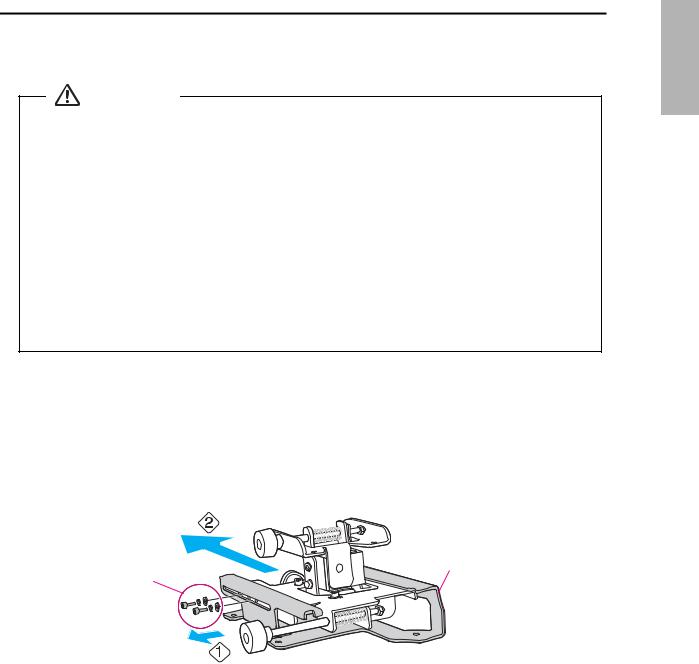
5 Installing the Projector |
English |
|
Make sure to follow the steps below to install the wall mount. If you ignore these steps, the wall mount could |
||
|
||
fall and cause personal injury or property damage. |
|
|
Warning |
|
When you mount the projector on the wall with the wall mount, the wall requires enough strength to hold the projector and the wall mount.
This wall mount should be installed on a concrete wall. Confirm the weight of the projector and the wall mount before installation, and maintain the strength of the wall. If the wall is not strong enough, reinforce the wall before installation.
The maximum combined weight of the projector and the wall mount is 32.6 lb (14.8 kg).
Do not hang the rest of the cable over the wall mount.
Install the wall mount so that it can sufficiently support the weight of the projector and wall mount, and resist any horizontal vibration. Use M10 nuts and bolts and make sure to use appropriate wall anchors for your wall type. Nuts and bolts smaller than M10 could cause the wall mount to fall.
Epson accepts no responsibility for any damage or injury caused by lack of wall strength or inadequate installation.
ADisassemble the parts
Remove the slide plate from the 3-axis adjustment unit.
•Remove the M4 x 12 mm hexagon socket head cap bolts (x2) ( ).
).
•Remove the slide plate from the 3-axis adjustment unit ( .
.
Slide plate
M4 x 12 mm hexagon socket head cap bolts
(x2)
23

BAssemble the parts
1.Assemble the wall plate.
Assemble the three plates into one unit, and secure them with the M4 x 12 mm hexagon socket head cap bolts (x6) supplied.
Washer
Spring washer
M4 x 12 mm hexagon socket head cap bolts
2.Attach the slide plate to the projector.
Attach the slide plate to the projector using the M4 x 12 mm hexagon socket head cap bolts (x4) supplied.
Slide plate |
M4 x 12 mm hexagon socket head cap |
bolts |
|
|
Spring washer |
|
Washer |
24

3. |
Attach the 3-axis adjustment unit to the wall mount. |
|
|
|
|
|
• Decide which position you want to use for installing the 3-axis adjustment unit. |
|
|
||
|
Mount it at the |
stamp when the image is less than 75 inches (diagonally), or at the |
stamp |
English |
|
|
: Less than 75 inches |
: 75 inches or more |
|
||
|
when the projected image is 75 inches or more (diagonally). |
|
|
|
|
•Tighten the M4 x 12 mm hexagon socket head cap bolts (x4) supplied to install the 3-axis adjustment unit.
M4 x 12 mm hexagon socket  head cap bolts
Spring washer 

Washer 
Bolt installation positions
When the diagonal image is less than 75 inches |
When the diagonal image is 75 inches or more |
|||||||||||||||||||||||||||
|
|
|
|
|
|
|
|
|
|
|
|
|
|
|
|
|
|
|
|
|
|
|
|
|
|
|
|
|
|
|
|
|
|
|
|
|
|
|
|
|
|
|
|
|
|
|
|
|
|
|
|
|
|
|
|
|
|
|
|
|
|
|
|
|
|
|
|
|
|
|
|
|
|
|
|
|
|
|
|
|
|
|
|
|
|
|
|
|
|
|
|
|
|
|
|
|
|
|
|
|
|
|
|
|
|
|
|
|
|
|
|
|
|
|
|
|
|
|
|
|
|
|
|
|
|
|
|
|
|
|
|
|
|
|
|
|
|
|
|
|
|
|
|
|
|
|
|
|
|
|
|
|
|
|
|
|
|
|
|
|
|
|
|
|
|
|
|
|
|
|
|
|
|
|
|
|
|
|
|
|
|
|
|
|
|
|
|
|
|
|
|
|
|
|
|
|
|
|
|
|
|
|
|
|
|
|
|
|
|
|
|
|
|
|
|
|
|
|
|
|
|
|
|
|
|
|
|
|
|
|
|
25
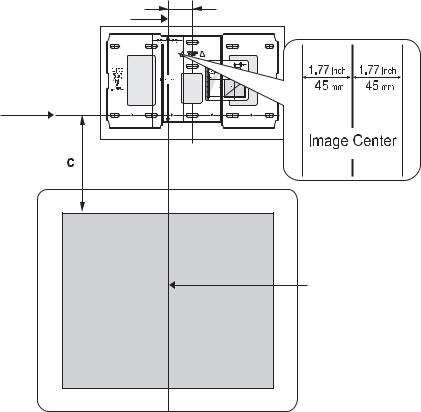
CInstall the wall plate on the wall
1.Determine the template sheet position.
•From the projection distance table, confirm the screen size (S) and the distance between the projection surface and wall plate (c).
•Align the Image Center line (vertical) of the template sheet with the center line (vertical) of the projection surface.
Confirm where the beams or studs are within the wall, and shift the position of the template left or right as necessary.
The position can be shifted horizontally left or right from the center line of the projection surface up to a maximum of 1.77 in. (45 mm.)
•Align the  line (horizontal) on the template with the height of (c).
2.8in.
(70.5 mm)
Image Center line of template sheet
 line of template sheet
Center line of projection surface
2.Attach the template sheet to the wall.
If you need to install a junction box, you can use the cutout areas in the wall plate for the box. The junction box needs to be recessed into the wall if you want to use the wall plate cover.
26
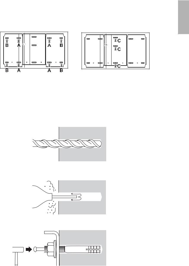
3. Determine the position of the wall plate’s mounting holes. |
|
|
Use at least three mounting holes. |
|
|
• If you are securing the wall plate in four places, drill the holes indicated by A or B in the illustration |
English |
|
below. |
||
• If you are securing the wall plate in three places, drill the holes indicated by C in the illustration |
||
below. |
||
|
|
|
|
|
|
|
|
|
|
|
|
|
|
|
|
|
|
|
|
|
|
|
|
|
|
|
|
|
Four mounting holes |
|
|
|
|||
Three mounting holes |
||||||
Steps 4 to 8 below provide instructions for attaching the wall plate to a concrete wall.
4.Drill holes of the following diameters and depths.
Drill diameter |
0.41 in. (10.5 mm) |
|
|
Pilot hole depth |
1.8 in. (45 mm) |
|
|
Anchor hole depth |
1.6 in. (40 mm) |
|
|
5.Remove the template sheet.
6.Use a device such as a dust pump to clean out concrete dust from the hole.
7.Position the wall plate on the wall and insert M10 x 60 mm expansion anchors into the holes. Attach the nut and tap it with a hammer until the core touches the top of the anchor.
27
Loading...