


 Loading...
SERVICE MANUAL
Color Inkjet Printer
EPSON B-300/B-308
EPSON B-500DN/B-508DN
EPSON B-310N/B-318N
EPSON B-510DN/B-518DN
Confidential
SEIJ07-013
Notice:
All rights reserved. No part of this manual may be reproduced, stored in a retrieval system, or transmitted in any form or by any means, electronic, mechanical, photocopying, recording, or otherwise, without the prior written permission of SEIKO EPSON CORPORATION.
The contents of this manual are subject to change without notice.
All effort have been made to ensure the accuracy of the contents of this manual. However, should any errors be detected, SEIKO EPSON would greatly appreciate being informed of them.
The above not withstanding SEIKO EPSON CORPORATION can assume no responsibility for any errors in this manual or the consequences thereof.
EPSON is a registered trademark of SEIKO EPSON CORPORATION.
General Notice: |
Other product names used herein are for identification purpose only and may be trademarks or registered trademarks of their |
|
respective owners. EPSON disclaims any and all rights in those marks. |
Copyright © 2009 SEIKO EPSON CORPORATION.
IJP LP CS Quality Assurance Department
Confidential
|
PRECAUTIONS |
Precautionary notations throughout the text are categorized relative to 1) Personal injury and 2) damage to equipment. |
|
DANGER |
Signals a precaution which, if ignored, could result in serious or fatal personal injury. Great caution should be exercised in performing procedures preceded by |
|
DANGER Headings. |
WARNING |
Signals a precaution which, if ignored, could result in damage to equipment. |
The precautionary measures itemized below should always be observed when performing repair/maintenance procedures.
DANGER
1.ALWAYS DISCONNECT THE PRODUCT FROM THE POWER SOURCE AND PERIPHERAL DEVICES PERFORMING ANY MAINTENANCE OR REPAIR PROCEDURES.
2.NO WORK SHOULD BE PERFORMED ON THE UNIT BY PERSONS UNFAMILIAR WITH BASIC SAFETY MEASURES AS DICTATED FOR ALL ELECTRONICS TECHNICIANS IN THEIR LINE OF WORK.
3.WHEN PERFORMING TESTING AS DICTATED WITHIN THIS MANUAL, DO NOT CONNECT THE UNIT TO A POWER SOURCE UNTIL INSTRUCTED TO DO SO. WHEN THE POWER SUPPLY CABLE MUST BE CONNECTED, USE EXTREME CAUTION IN WORKING ON POWER SUPPLY AND OTHER ELECTRONIC COMPONENTS.
4.WHEN DISASSEMBLING OR ASSEMBLING A PRODUCT, MAKE SURE TO WEAR GLOVES TO AVOID INJURIER FROM METAL PARTS WITH SHARP EDGES.
WARNING
1.REPAIRS ON EPSON PRODUCT SHOULD BE PERFORMED ONLY BY AN EPSON CERTIFIED REPAIR TECHNICIAN.
2.MAKE CERTAIN THAT THE SOURCE VOLTAGES IS THE SAME AS THE RATED VOLTAGE, LISTED ON THE SERIAL NUMBER/RATING PLATE. IF THE EPSON PRODUCT HAS A PRIMARY AC RATING DIFFERENT FROM AVAILABLE POWER SOURCE, DO NOT CONNECT IT TO THE POWER SOURCE.
3.ALWAYS VERIFY THAT THE EPSON PRODUCT HAS BEEN DISCONNECTED FROM THE POWER SOURCE BEFORE REMOVING OR REPLACING PRINTED CIRCUIT BOARDS AND/OR INDIVIDUAL CHIPS.
4.IN ORDER TO PROTECT SENSITIVE MICROPROCESSORS AND CIRCUITRY, USE STATIC DISCHARGE EQUIPMENT, SUCH AS ANTI-STATIC WRIST STRAPS, WHEN ACCESSING INTERNAL COMPONENTS.
5.REPLACE MALFUNCTIONING COMPONENTS ONLY WITH THOSE COMPONENTS BY THE MANUFACTURE; INTRODUCTION OF SECOND-SOURCE ICs OR OTHER NON-APPROVED COMPONENTS MAY DAMAGE THE PRODUCT AND VOID ANY APPLICABLE EPSON WARRANTY.
6.WHEN USING COMPRESSED AIR PRODUCTS; SUCH AS AIR DUSTER, FOR CLEANING DURING REPAIR AND MAINTENANCE, THE USE OF SUCH PRODUCTS CONTAINING FLAMMABLE GAS IS PROHIBITED.
Confidential
About This Manual
This manual describes basic functions, theory of electrical and mechanical operations, maintenance and repair procedures of the printer. The instructions and procedures included herein are intended for the experienced repair technicians, and attention should be given to the precautions on the preceding page.
Manual Configuration
This manual consists of six chapters and Appendix.
CHAPTER 1.PRODUCT DESCRIPTIONS
Provides a general overview and specifications of the product.
CHAPTER 2.OPERATING PRINCIPLES
Describes the theory of electrical and mechanical operations of the product.
CHAPTER 3.TROUBLESHOOTING
Describes the step-by-step procedures for the troubleshooting.
CHAPTER 4.DISASSEMBLY / ASSEMBLY
Describes the step-by-step procedures for disassembling and assembling the product.
CHAPTER 5.ADJUSTMENT
Provides Epson-approved methods for adjustment.
CHAPTER 6.MAINTENANCE
Provides preventive maintenance procedures and the lists of Epsonapproved lubricants and adhesives required for servicing the product.
APPENDIX Provides the following additional information for reference:
• Connector Summary
Symbols Used in this Manual
Various symbols are used throughout this manual either to provide additional information on a specific topic or to warn of possible danger present during a procedure or an action. Be aware of all symbols when they are used, and always read NOTE, CAUTION, or WARNING messages.
ADJUSTMENT |
Indicates an operating or maintenance procedure, practice or condition |
|
REQUIRED |
that is necessary to keep the product’s quality. |
|
CAUTION |
Indicates an operating or maintenance procedure, practice, or condition |
|
that, if not strictly observed, could result in damage to, or destruction of, |
||
|
||
|
equipment. |
|
CHECK |
May indicate an operating or maintenance procedure, practice or |
|
POINT |
condition that is necessary to accomplish a task efficiently. It may also |
|
|
provide additional information that is related to a specific subject, or |
|
|
comment on the results achieved through a previous action. |
|
WARNING |
Indicates an operating or maintenance procedure, practice or condition |
|
that, if not strictly observed, could result in injury or loss of life. |
||
|
REASSEMBLY Indicates that a particular task must be carried out according to a certain standard after disassembly and before re-assembly, otherwise the qual-
ity of the components in question may be adversely affected.
Confidential

|
|
Revision Status |
|
|
|
Revision |
Date of Issue |
Description |
A |
April 1, 2008 |
First Release |
|
|
|
B |
May 16, 2008 |
Revised Contents |
|
|
Chapter 3 |
|
|
Descriptions have been added in Table 3-26 “Troubleshooting Ink Suction / Waste Ink Problems” (p70). |
|
|
Chapter 4 |
|
|
Made changes in 4.1.2 Tools (p75). |
|
|
Made changes in 4.3.4 Using Acetate Tape (p80). |
|
|
Made changes in 4.5.6.2 Front Housing Assy (p92). |
|
|
Made changes in 4.5.7.2 Upper Housing (p94). |
|
|
Made changes in 4.5.7.3 Cover Open Sensor (p96). |
|
|
Made changes in 4.6.3 AID Board (p100). |
|
|
Made changes in 4.6.5 Power Supply Unit (p106). |
|
|
Made changes in 4.7.1.1 IC Holder Assy (p108). |
|
|
Made changes in 4.7.1.3 CV Drive Assy (p116). |
|
|
“CAUTION” has been added in 4.7.3.1 Printhead (p121). |
|
|
Made changes in 4.7.3.3 APG Assy / Sub Board (p125). |
|
|
Made changes in 4.7.3.4 ASF Encoder Assy (p128). |
|
|
Made changes in 4.7.3.5 CR Motor (p129). |
|
|
Made changes in 4.7.3.6 Carriage Assy (p131). |
|
|
Made changes in 4.7.4.3 ASF Motor Assy (p136). |
|
|
Made changes in 4.7.4.4 Planet Lock Assy (p138). |
|
|
Made changes in 4.7.4.9 Paper Guide Bank Assy (p149). |
|
|
Made changes in 4.7.5.1 PF Motor (p156). |
|
|
Made changes in 4.7.5.5 Front Paper Guide & EJ Roller Assy (p162). |
|
|
Made changes in 4.7.6.1 Ink System (p165). |
|
|
Made changes in 4.7.6.2 EJ Waste Ink Assy (p168). |
|
|
Made changes in 4.7.6.3 EJC Sensor (p169). |
|
|
Chapter 5 |
|
|
Made changes in Table 5-1 “Adjustment Items and Overviews” (p171). |
|
|
Descriptions have been added in Table 5-2 “Maintenance Items” (p174). |
|
|
Descriptions have been added in Table 5-3 “Additional Functions” (p175). |
|
|
Made changes in 5.2.6 Head angular adjustment (p181). |
|
|
|
Confidential

Revision |
Date of Issue |
Description |
C |
March 31, 2009 |
Revised Contents |
|
|
Chapter 1 |
|
|
Descriptions have been added in Table 1-12 “Power Supply Specifications” (p20). |
|
|
Chapter 3 |
|
|
Descriptions have been added in Table 3-23 “Troubleshooting Print Quality Problems” (p67). |
|
|
Descriptions have been added in Table 3-25 “Troubleshooting Ink Supply Problems” (p69). |
|
|
Chapter 4 |
|
|
Descriptions have been added in 4.3.1 Releasing Carriage Lock (p79). |
|
|
“REASSEMBLY” has been added in 4.7.1.1 IC Holder Assy (p108). |
|
|
“REASSEMBLY” has been added in 4.7.1.3 CV Drive Assy (p116). |
|
|
Chapter 5 |
|
|
Made changes in Table 5-1 “Adjustment Items and Overviews” (p171). |
|
|
Made changes in Table 5-4 “Adjustment Items” (p176). |
|
|
Made changes in 5.2.6 Head angular adjustment (p181). |
|
|
Made changes in 5.2.7 AID inspection (p184). |
|
|
Descriptions have been added in 5.2.10 Paper Skew Adjustment (p187). |
|
|
Descriptions have been added in 5.2.11 ACL Failed Counter Initialization (p189). |
|
|
Chapter 6 |
|
|
Descriptions have been added in Table 6-2 “Specified Lubricant” (p198). |
|
|
|
Confidential

Revision |
Date of Issue |
Description |
D |
September 17, 2009 |
Revised Contents |
|
|
Chapter 2 |
|
|
Made changes in Figure 2-1 “Printer Mechanism Block Diagram” (p31). |
|
|
Made changes in Table 2-1 “PG Settings / Cam Diagram” (p32). |
|
|
Descriptions have been added in 2.3 Optical Sensor Control (p34). |
|
|
Chapter 3 |
|
|
Made changes in Table 3-3 “Error Messages and Possible Causes” (p37). |
|
|
Descriptions have been added in 3.3.2 Fatal Error (p48). |
|
|
Chapter 4 |
|
|
Made changes in 4.7.3.1 Printhead (p121). |
|
|
“ADJUSTMENT REQUIRED” has been changed in 4.7.3.5 CR Motor (p129). |
|
|
“ADJUSTMENT REQUIRED” has been changed in 4.7.5.1 PF Motor (p156). |
|
|
Chapter 5 |
|
|
Made changes in Table 5-1 “Adjustment Items and Overviews” (p171). |
|
|
Descriptions have been added in Table 5-2 “Maintenance Items” (p174). |
|
|
“CHECKPOINT” has been added and made changes in 5.2.11 ACL Failed Counter Initialization (p189). |
|
|
Made changes in 5.3.2 PF Belt Tension Adjustment (p193). |
|
|
Made changes in 5.3.3 FD Belt Tension Adjustment (p194). |
|
|
|
Confidential

Revision |
Date of Issue |
Description |
E |
November 26, 2009 |
Revised Contents |
|
|
All chapters |
|
|
Descriptions about B-310N/B-318N/B-510DN/B-518DN are added. |
|
|
Chapter 1 |
|
|
Made changes in 1.1 Features (p14) |
|
|
Made changes in Table 1-3 “Product No. of Ink Cartridges” (p15) |
|
|
Made changes in Table 1-6 “Print Mode (Color/Monochrome)” (p16) |
|
|
Made changes in Table 1-7 “Supported Paper” (p17) |
|
|
Made changes in Table 1-12 “Power Supply Specifications” (p20) |
|
|
Made changes in Table 1-14 “Operation Buttons, LED, LCD (B-500DN/B-508DN/B-310N/B-318N/B-510DN/B- |
|
|
518DN)” (p22) |
|
|
Made changes in Table 1-16 “LEDs and LCD Indications” (p23) |
|
|
1.6 Various Settings (p24) has been added |
|
|
Made changes in Figure 1-10 “Network Status Sheet Sample (2)” (p29) |
|
|
Chapter 3 |
|
|
Made changes in Table 3-3 “Error Messages and Possible Causes” (p37) |
|
|
Made changes in Table 3-12 “Check Point for Fatal Error of Each Phenomenon” (p52) |
|
|
Made changes in Table 3-19 “FFC/harness Connection Error (SUB Board)” (p65) |
|
|
|
Confidential

Revision |
Date of Issue |
Description |
|
E |
November 26, 2009 |
Chapter 4 |
|
“CHECKPOINT” has been added and made changes in 4.4.3 Cassette Assy (p85) |
|||
|
|
||
|
|
Made changes in 4.5.6.2 Front Housing Assy (p92) |
|
|
|
Made changes in 4.6.2 Network Board (B-500DN/B-508DN/B-310N/B-318N/B-510DN/B-518DN only) (p99) |
|
|
|
Made changes in 4.6.3 AID Board (p100) |
|
|
|
Made changes in 4.7.1.1 IC Holder Assy (p108) |
|
|
|
Made changes in 4.7.1.3 CV Drive Assy (p116) |
|
|
|
Made changes in 4.7.2 Lower Housing (p117) |
|
|
|
“CHECKPOINT” has been added and made changes in 4.7.3.1 Printhead (p121) |
|
|
|
“CHECKPOINT” has been added and made changes in 4.7.3.3 APG Assy / Sub Board (p125) |
|
|
|
“CHECKPOINT” has been added in 4.7.3.4 ASF Encoder Assy (p128) |
|
|
|
“CHECKPOINT” has been added and made changes in 4.7.4.4 Planet Lock Assy (p138) |
|
|
|
“CHECKPOINT” has been added in 4.7.4.5 ASF Sub Encoder (p142) |
|
|
|
Made changes in 4.7.4.6 Retard Transfer Assy (p143) |
|
|
|
Made changes in 4.7.4.7 FASF Retard Assy (p144) |
|
|
|
“CHECKPOINT” has been added and made changes in 4.7.5.4 Left/Right Upper Paper Guide (p160) |
|
|
|
Made changes in 4.7.6.1 Ink System (p165) |
|
|
|
Chapter 5 |
|
|
|
Made changes in Table 5-3 “Additional Functions” (p175) |
|
|
|
Chapter 6 |
|
|
|
Made changes in Table 6-2 “Specified Lubricant” (p198) |
|
|
|
Made changes in 6.1.3 Lubrication (p198) |
|
|
|
Chapter 7 |
|
|
|
Made changes in Figure 7-1 “Block Diagram” (p208) |
|
|
|
|
Confidential

EPSON B-300/B-308/B-500DN/B-508DN/B-310N/B-318N/B-510DN/B-518DN |
Revision E |
Contents
Chapter 1 |
PRODUCT DESCRIPTION |
|
||
1.1 |
Features............................................................................................................... |
|
14 |
|
1.2 |
Printing Specifications........................................................................................ |
15 |
||
|
1.2.1 |
Basic Specifications................................................................................. |
15 |
|
|
1.2.2 |
Ink Cartridges .......................................................................................... |
15 |
|
|
1.2.3 Maintenance Box..................................................................................... |
16 |
||
|
1.2.4 |
Print Mode ............................................................................................... |
16 |
|
|
1.2.5 |
Supported Paper....................................................................................... |
17 |
|
|
1.2.6 |
Printing Area ........................................................................................... |
19 |
|
1.3 |
Interface |
.............................................................................................................. |
19 |
|
|
1.3.1 |
USB Interface .......................................................................................... |
19 |
|
|
1.3.2 |
Network Interface |
|
|
|
(B-500DN/B-508DN/B-310N/B-318N/B-510DN/B-518DN only) .......... |
19 |
||
1.4 |
General Specifications........................................................................................ |
20 |
||
|
1.4.1 |
Electrical Specifications .......................................................................... |
20 |
|
|
1.4.2 |
Safety Approvals (Safety standards/EMI)............................................... |
20 |
|
|
1.4.3 |
Environmental Conditions....................................................................... |
21 |
|
|
1.4.4 |
Durability................................................................................................. |
21 |
|
1.5 |
Control Panel ...................................................................................................... |
22 |
||
|
1.5.1 |
Operation Buttons.................................................................................... |
22 |
|
|
1.5.2 LEDs and LCD Indications ..................................................................... |
23 |
||
1.6 |
Various Settings.................................................................................................. |
24 |
||
|
1.6.1 |
Panel Operation ....................................................................................... |
24 |
|
|
1.6.1.1 |
Menu Configuration |
|
|
|
|
|
(B-500DN/B-508DN/B-310N/B-318N/B-510DN/B-518DN only) .... |
24 |
|
1.6.1.2 |
Panel Operation Lock Setting |
|
|
|
|
|
(B-310N/B-318N/B-510DN/B-518DN only) ...................................... |
25 |
|
1.6.1.3 Forced Power OFF ............................................................................. |
26 |
||
|
1.6.2 |
AID Function Setting .............................................................................. |
26 |
|
|
1.6.2.1 |
AID Detection Cleaning |
|
|
|
|
|
(B-310N/B-318N/B-510DN/B-518DN only) ...................................... |
26 |
|
1.6.2.2 AID High Quality Mode/Dot Missing Tolerance Mode .................... |
27 |
||
|
1.6.2.3 Monochrome Priority Mode............................................................... |
27 |
||
1.6.3 Low Speed Mode (MPBF Priority Mode) |
|
(B-310N/B-318N/B-510DN/B-518DN only)............................................ |
28 |
1.7 Status Sheet ........................................................................................................ |
28 |
Chapter 2 Operating Principles |
|
||
2.1 |
Overview ............................................................................................................ |
31 |
|
|
2.1.1 |
Printer Mechanism .................................................................................. |
31 |
|
2.1.2 |
Printhead.................................................................................................. |
31 |
|
2.1.3 |
PG Setting................................................................................................ |
32 |
2.2 |
Motors and Sensors ............................................................................................ |
33 |
|
2.3 |
Optical Sensor Control ....................................................................................... |
34 |
|
Chapter 3 |
Troubleshooting |
|
||
3.1 |
Overview |
............................................................................................................ |
36 |
|
|
3.1.1 |
Troubleshooting on Motors and Sensors................................................. |
36 |
|
3.2 |
Error Messages and Possible Causes.................................................................. |
37 |
||
|
3.2.1 |
List of Error Indications .......................................................................... |
37 |
|
3.3 |
Troubleshooting.................................................................................................. |
39 |
||
|
3.3.1 |
Troubleshooting by Error Message ......................................................... |
39 |
|
|
3.3.2 |
Fatal Error................................................................................................ |
48 |
|
|
3.3.2.1 |
Check Point for Fatal Error of Each Phenomenon............................. |
52 |
|
|
3.3.2.2 |
Check Result of Fatal Errors when Abnormality Occurs................... |
60 |
|
3.4 |
Troubleshooting by Symptom (no error indications) ......................................... |
66 |
||
|
3.4.1 |
Troubleshooting Printer Mechanism Problems....................................... |
66 |
|
|
3.4.2 |
Troubleshooting Electrical Problems ...................................................... |
68 |
|
|
3.4.3 |
Troubleshooting Ink Supply / Waste Ink Problems ................................ |
69 |
|
|
3.4.4 |
Troubleshooting I/F-related Problems..................................................... |
71 |
|
3.5 |
Troubleshooting Duplex Unit Problems............................................................. |
72 |
||
10
Confidential
EPSON B-300/B-308/B-500DN/B-508DN/B-310N/B-318N/B-510DN/B-518DN |
Revision E |
Chapter 4 Disassembly and Assembly
4.1 Overview |
............................................................................................................ |
74 |
||
|
4.1.1 |
Precautions .............................................................................................. |
74 |
|
|
4.1.2 |
Tools ........................................................................................................ |
75 |
|
|
4.1.3 |
Screws...................................................................................................... |
75 |
|
|
4.1.4 |
Work Completion Checklist .................................................................... |
75 |
|
|
4.1.5 |
Preparation for Disassembling ................................................................ |
76 |
|
|
4.1.6 |
Orientation Definition ............................................................................. |
76 |
|
4.2 Disassembly Flowchart ...................................................................................... |
77 |
|||
4.3 |
Basic Operations................................................................................................. |
79 |
||
|
4.3.1 |
Releasing Carriage Lock ......................................................................... |
79 |
|
|
4.3.2 |
Handling Ink Supply Parts....................................................................... |
80 |
|
|
4.3.3 |
Handling Ink System Parts ...................................................................... |
80 |
|
|
4.3.4 |
Using Acetate Tape ................................................................................. |
80 |
|
|
4.3.5 |
Protection for Transportation .................................................................. |
81 |
|
4.4 Consumables & Accessories .............................................................................. |
83 |
|||
|
4.4.1 |
Ink Cartridge............................................................................................ |
83 |
|
|
4.4.2 Maintenance Box Assy............................................................................ |
84 |
||
|
4.4.3 |
Cassette Assy........................................................................................... |
85 |
|
|
4.4.4 |
Rear Cover / Duplex Unit........................................................................ |
86 |
|
4.5 |
Removing Exterior Parts .................................................................................... |
87 |
||
|
4.5.1 IC Holder Cover ...................................................................................... |
87 |
||
|
4.5.2 |
Cover Ink Eject Box ................................................................................ |
88 |
|
|
4.5.3 Front ASF Cover Assy ............................................................................ |
88 |
||
|
4.5.4 |
Stacker Assy / Paper Support .................................................................. |
89 |
|
|
4.5.4.1 |
Stacker Assy ....................................................................................... |
89 |
|
|
4.5.4.2 |
Paper Support ..................................................................................... |
89 |
|
|
4.5.5 |
Panel Unit ................................................................................................ |
90 |
|
|
4.5.6 |
Cover Printer Assy /Housing Front Assy ................................................ |
91 |
|
|
4.5.6.1 |
Cover Printer Assy ............................................................................. |
91 |
|
|
4.5.6.2 |
Front Housing Assy............................................................................ |
92 |
|
|
4.5.7 Connector Cover / Upper Housing .......................................................... |
94 |
||
|
4.5.7.1 |
Connector Cover................................................................................. |
94 |
|
|
4.5.7.2 Upper Housing ................................................................................... |
94 |
||
|
4.5.7.3 Cover Open Sensor............................................................................. |
96 |
||
4.6 Removing the Circuit Boards ............................................................................. |
97 |
|||
|
4.6.1 Main Board.............................................................................................. |
97 |
||
|
4.6.2 Network Board |
|
||
|
(B-500DN/B-508DN/B-310N/B-318N/B-510DN/B-518DN only) .......... |
99 |
||
4.6.3 AID Board ............................................................................................. |
100 |
|
4.6.4 Disassembling the Panel Unit................................................................ |
103 |
|
4.6.4.1 |
Panel Board ...................................................................................... |
104 |
4.6.4.2 |
Optical Tube, Buttons ...................................................................... |
105 |
4.6.5 Power Supply Unit ................................................................................ |
106 |
|
4.7 Removing the Printer Major Components........................................................ |
108 |
|
4.7.1 Removing the Ink System Components ................................................ |
108 |
|
4.7.1.1 IC Holder Assy................................................................................. |
108 |
|
4.7.1.2 Sub-B Board..................................................................................... |
115 |
|
4.7.1.3 CV Drive Assy ................................................................................. |
116 |
|
4.7.2 Lower Housing ...................................................................................... |
117 |
|
4.7.3 Disassembling the Carriage Components.............................................. |
121 |
|
4.7.3.1 |
Printhead........................................................................................... |
121 |
4.7.3.2 CR Scale........................................................................................... |
124 |
|
4.7.3.3 APG Assy / Sub Board..................................................................... |
125 |
|
4.7.3.4 ASF Encoder Assy ........................................................................... |
128 |
|
4.7.3.5 CR Motor.......................................................................................... |
129 |
|
4.7.3.6 |
Carriage Assy ................................................................................... |
131 |
4.7.4 Disassembling the Paper Loading Mechanism Components ................ |
133 |
|
4.7.4.1 Rear ASF Assy ................................................................................. |
133 |
|
4.7.4.2 RH Sensor / RP Sensor.................................................................... |
135 |
|
4.7.4.3 ASF Motor Assy............................................................................... |
136 |
|
4.7.4.4 |
Planet Lock Assy.............................................................................. |
138 |
4.7.4.5 ASF Sub Encoder ............................................................................. |
142 |
|
4.7.4.6 |
Retard Transfer Assy........................................................................ |
143 |
4.7.4.7 FASF Retard Assy............................................................................ |
144 |
|
4.7.4.8 |
LD Roller / Retard Roller................................................................. |
146 |
4.7.4.9 Paper Guide Bank Assy.................................................................... |
149 |
|
4.7.4.10 PEF Sensor ..................................................................................... |
153 |
|
4.7.4.11 PER Sensor..................................................................................... |
153 |
|
4.7.4.12 Rear Paper Guide / PE Sensor....................................................... |
154 |
|
4.7.4.13 |
Pick-up Assy .................................................................................. |
155 |
4.7.5 Disassembling the Paper Feed Mechanism Components...................... |
156 |
|
4.7.5.1 PF Motor .......................................................................................... |
156 |
|
4.7.5.2 PF Encoder ....................................................................................... |
158 |
|
4.7.5.3 EJ Frame Assy.................................................................................. |
159 |
|
4.7.5.4 |
Left/Right Upper Paper Guide ......................................................... |
160 |
4.7.5.5 Front Paper Guide & EJ Roller Assy ............................................... |
162 |
|
4.7.5.6 |
PF Roller Assy ................................................................................. |
163 |
4.7.6 Disassembling the Ink System Components ......................................... |
165 |
|
|
|
11 |
Confidential

 EPSON B-300/B-308/B-500DN/B-508DN/B-310N/B-318N/B-510DN/B-518DN
4.7.6.1 |
Ink System. ....................................................................................... |
165 |
4.7.6.2 EJ Waste Ink Assy............................................................................ |
168 |
|
4.7.6.3 |
EJC Sensor . ...................................................................................... |
169 |
Chapter 5 ADJUSTMENT
5.1 Adjustment Items and Overview . ..................................................................... |
171 |
|
5.1.1 |
Servicing Adjustment Item List............................................................. |
171 |
5.1.2 |
Required Adjustments . .......................................................................... |
176 |
5.2 Adjustment by Using Adjustment Program ..................................................... |
178 |
|
5.2.1 |
Top Margin Adjustment (Rear/Front) ................................................... |
178 |
5.2.2 Bi-D Adjustment . .................................................................................. |
178 |
|
5.2.3 |
First Dot Position Adjustment (Front/Rear) .......................................... |
179 |
5.2.4 PW Adjustment . .................................................................................... |
179 |
|
5.2.5 |
PF Adjustment (Rear/Front) .................................................................. |
180 |
5.2.6 |
Head angular adjustment ....................................................................... |
181 |
5.2.7 |
AID inspection. ...................................................................................... |
184 |
5.2.8 Printer Mechanism Operation Check .................................................... |
184 |
|
5.2.9 MAC Address Setting (B-500DN/B-508DN/B-310N/B-318N/B-510DN/ |
||
B-518DN only) . ....................................................................................... |
185 |
|
5.2.10 Paper Skew Adjustment . ..................................................................... |
187 |
|
5.2.11 |
ACL Failed Counter Initialization....................................................... |
189 |
5.2.12 |
Compulsion Uni-d Print Setting .......................................................... |
190 |
5.3 Adjustment without Using Adjustment Program ............................................. |
191 |
|
5.3.1 PG Adjustment . ..................................................................................... |
191 |
|
5.3.2 |
PF Belt Tension Adjustment ................................................................. |
193 |
5.3.3 FD Belt Tension Adjustment................................................................. |
194 |
|
Revision E
Chapter 7 APPENDIX
7.1 Connector Summary. ........................................................................................ |
208 |
Chapter 6 |
MAINTENANCE |
|
|
6.1 Overview |
. ......................................................................................................... |
196 |
|
6.1.1 |
Cleaning. ................................................................................................ |
196 |
|
6.1.2 |
Service Maintenance . ............................................................................ |
197 |
|
6.1.2.1 |
Printhead cleaning ............................................................................ |
197 |
|
6.1.2.2 |
Service Call . ..................................................................................... |
197 |
|
6.1.3 |
Lubrication . ........................................................................................... |
198 |
|
12
Confidential

C H A P T E R
1
PRODUCT DESCRIPTION
Confidential

EPSON B-300/B-308/B-500DN/B-508DN/B-310N/B-318N/B-510DN/B-518DN |
Revision E |
1.1 Features
B-300/B-308/B-500DN/B-508DN/B-310N/B-318N/B-510DN/B-518DN is businessoriented A4 inkjet printers, which offers high print quality and high durability with low running costs like laser printers. The main features are:
F-Mach Turbo 2 (180 nozzles x 8 columns) Printhead
High durability (up to 100,000 sheets can be printed)
The default mode enables high-speed printing on plain paper
Large capacity ink cartridges
Large capacity paper feeders (front: 500 sheets, rear: 150 sheets)
Automatic duplex printing using the duplex unit (B-500DN/B-508DN/B-510DN/B-518DN include the unit as standard. For B-300/ B-308/B-310N/B-318N, the unit is available as an option.)
2 Line LCD on the control panel offers high level of visibility and operability. (B-500DN/B-508DN/B-310N/B-318N/B-510DN/B-518DN only)
Wired LAN is supported. (B-500DN/B-508DN/B-310N/B-318N/B-510DN/B-518DN only)
Dimensions & Weight
Table 1-1. Dimensions & Weight
|
B-300/B-308 |
B-310N/B-318N |
B-500DN/B-508DN B-510DN/B-518DN |
|
|
|
|
||
Dimensions |
480 mm (W) x 420 mm (D) x 312 mm (H)*1 |
480 mm (W) x 489 mm (D) x 312 mm (H)*2 |
||
Weight |
9.85 kg*3 |
9.95 kg*3 |
10.69 kg*3 |
10.70 kg*4/10.79 kg*5 |
*1:The optional duplex unit is not included. The stackers are retracted. *2:The duplex unit is included. The stackers are retracted.
*3:The ink cartridges, the power cord and the duplex unit are not included. *4:The ink cartridges and the power cord are not included.
*5:For the EAI model, the ink cartridges, the power cord, and the Casstte Assy are not included, but the Cassette Assy for legal size paper is included instead.
B-300/B-308
B-500DN/B-508DN/B-310N/B-318N/B-510DN/B-518DN
Figure 1-1. External View
PRODUCT DESCRIPTION |
Features |
14 |
|
|
Confidential |

EPSON B-300/B-308/B-500DN/B-508DN/B-310N/B-318N/B-510DN/B-518DN |
Revision E |
1.2 |
Printing Specifications |
||||
1.2.1 |
Basic Specifications |
|
|||
|
|
Table 1-2. Printer Specifications |
|||
|
|
|
|
|
|
|
Item |
|
|
Specifications |
|
|
|
||||
Print method |
On-demand inkjet |
||||
|
|
|
|
||
Printhead |
Black: |
360 nozzles (180 nozzles x 2 columns) |
|||
Color: |
1,080 nozzles (180 nozzles x 2 columns per color) |
||||
|
|
||||
|
|
||||
Colors |
Cyan, Yellow, Magenta, Black |
||||
|
|
|
|||
Print direction |
Bi-directional minimum distance printing (logic seeking), |
||||
unidirectional printing |
|||||
|
|
||||
|
|
|
|||
|
|
Horizontal x Vertical (dpi) |
|||
Print resolution |
• 360 x 360 |
• 720 x 720 |
|||
|
|
• 1440 x 720 |
• 5760 x 1440 |
||
|
|
||||
Control code |
ESC/P Raster command |
||||
|
|
|
|||
Input buffer size |
256 KBytes |
|
|||
|
|
|
|||
Paper feed method |
Friction feed |
|
|||
|
|
|
|
|
|
Paper feeders |
• Front: |
|
500 sheets (plain paper) |
||
• Rear: |
|
150 sheets (plain paper) |
|||
|
|
|
|||
|
|
|
|||
Paper path |
• Rear feed, front out |
||||
• Front feed, front out |
|||||
|
|
||||
|
|
||||
Feed speed |
100 ms (25.4 mm feed) |
||||
|
|
||||
Line pitch |
Programmable in units of 0.01764 mm (1/1440 inch) |
||||
|
|
|
|
|
|
1.2.2 Ink Cartridges
The product numbers of the Epson ink cartridges for this printer are shown below.Product No.
Table 1-3. Product No. of Ink Cartridges
Color |
Size |
B-300/B-308/ |
B-500DN/ |
B-508DN/ |
|
B-310N/B-318N |
B-510DN |
B-518DN |
|||
|
|
||||
|
|
|
|
|
|
|
LL |
N/A |
Τ6181 |
Τ6271 |
|
Black |
|
|
|
|
|
L |
N/A |
Τ6171 |
Τ6261 |
||
|
|
|
|
|
|
|
M |
Τ6161 |
Τ6161 |
Τ6251 |
|
|
|
|
|
|
|
Cyan |
L |
N/A |
Τ6172 |
Τ6262 |
|
|
|
|
|
||
M |
Τ6162 |
Τ6162 |
Τ6252 |
||
|
|||||
|
|
|
|
|
|
Magenta |
L |
N/A |
Τ6173 |
Τ6263 |
|
|
|
|
|
||
M |
Τ6163 |
Τ6163 |
Τ6253 |
||
|
|||||
|
|
|
|
|
|
Yellow |
L |
N/A |
Τ6174 |
Τ6264 |
|
|
|
|
|
||
M |
Τ6164 |
Τ6164 |
Τ6254 |
||
|
|||||
|
|
|
|
|
Shelf life
Two years from production date (if unopened), six months after opening package.
Storage Temperature
Table 1-4. Storage Temperature
Situation |
Storage Temperature |
Limit |
|
|
|
Packed in the package |
-20 oC to 40 oC (-4oF to 104oF) |
1 month max. |
|
|
at 40 oC (104oF) |
Installed on the printer |
-20 oC to 40 oC (-4oF to 104oF) |
Dimensions
|
Table 1-5. Dimensions |
|
|
Ink Cartridge Size |
Dimensions |
|
|
M/L |
165.8 mm (W) x 106.6 mm (D) x 25.1 mm (H) |
|
|
LL |
280.8 mm (W) x 106.6 mm (D) x 25.1 mm (H) |
|
|
PRODUCT DESCRIPTION |
Printing Specifications |
15 |
Confidential

EPSON B-300/B-308/B-500DN/B-508DN/B-310N/B-318N/B-510DN/B-518DN |
Revision E |
CAUTION |
|
Do not use expired ink cartridge. |
|
|
Ink in the cartridges freezes if the cartridges left under a |
|
|
temperature of 10oC or lower. Once ink becomes frozen, it takes |
|
|
about three hours to thaw it under a temperature of 25oC. (when |
|
|
moved from -20oC environment.) |
1.2.3 Maintenance Box
Item |
|
|
Specifications |
|
|
|
|
||
Model number |
T6190 |
|
||
|
|
|
||
Dimensions |
|
86.2mm (W) x 236.9mm (D) x 56.5mm (H) |
||
|
|
|
|
|
|
|
Packed in the package |
-20oC to 40oC* (-4oF to 104oF) |
|
|
|
*1 month max. at 40 oC (104oF) |
||
|
|
|
||
Ambient temp. |
Installed on the printer |
-20oC to 40oC* (-4oF to 104oF) |
||
*1 month max. at 40 oC (104oF) |
||||
|
|
|
||
|
|
Transported with packed |
-20oC to 60oC* (-4oF to 140oF) |
|
|
|
*Within five days at 60 oC (140oF) |
||
|
|
|
||
|
|
|
||
CAUTION |
|
Do not disassemble the maintenance box. |
||
|
Do not touch the CSIC on the maintenance box. |
|||
|
Do not remove the film attached to the upper surface of the |
|||
|
|
maintenance box. |
|
|
When disposing of a used maintenance box, do not tilt it before putting it into a plastic bag.
If the maintenance box is removed and left unused for a long time, do not reuse it.
1.2.4 Print Mode
Table 1-6. Print Mode (Color/Monochrome)
|
Media |
Print Mode |
Resolution |
Dot Size |
Bi-d |
Micro |
|
|
|
(H x V) dpi |
(cps*1) |
Weave |
|
||||
|
|
|
|
|
|
|||
|
• Plain paper |
Draft |
360x360 |
Eco (450cps) |
ON |
OFF |
|
|
|
• Premium Bright |
|
|
|
|
|
|
|
|
Normal |
360x360 |
VSD-1 (360cps) |
ON |
OFF |
|
||
|
White Paper (EAI) |
|
||||||
|
|
|
|
|
|
|
||
|
• Bright White Inkjet |
Fine |
360x360 |
VSD-1 (360cps) |
ON |
OFF |
|
|
|
|
|||||||
|
Paper (Euro, Asia) |
|
|
|
|
|
|
|
|
Photo |
360x720 |
VSD-1 (360cps) |
ON |
OFF |
|
||
|
|
|||||||
|
|
|
|
|||||
|
|
|
|
|
|
|
|
|
|
|
|
Best Photo*2 |
720x720 |
VSD-2 (200cps) |
ON |
ON |
|
|
|
|
|
|||||
|
|
|
|
|
|
|
|
|
|
• Premium |
|
|
|
|
|
|
|
|
Presentation Paper |
|
|
|
|
|
|
|
|
Matte (EAI) |
Best Photo |
1440x720 |
VSD-3 (200cps) |
ON |
ON |
|
|
|
• Matte Paper Heavy- |
|
|
|
|
|
|
|
|
weight (Euro, Asia) |
|
|
|
|
|
|
|
|
|
|
|
|
|
|
|
|
|
• Presentation Paper |
|
|
|
|
|
|
|
|
Matte (EAI) |
Photo |
1440x720 |
VSD-3 (200cps) |
ON |
ON |
|
|
|
• Photo Quality Inkjet |
|
||||||
|
|
|
|
|
|
|
||
|
Paper (Euro, Asia) |
|
|
|
|
|
|
|
|
|
|
|
|
|
|
|
|
|
• Envelope |
Normal |
360x360 |
VSD-1 (360cps) |
OFF |
OFF |
|
|
|
|
|
|
|
|
|
|
|
|
|
|
Photo |
720x720 |
VSD-2 (200cps) |
OFF |
ON |
|
|
|
|
|
|
|
|
|
|
|
• Photo Paper |
Photo*2 |
720x720 |
VSD-2 (200cps) |
ON |
ON |
|
|
|
|
|||||||
|
|
|
|
|
|
|
|
|
|
|
|
Best Photo |
1440x1440 |
VSD-3 (200cps) |
ON |
ON |
|
|
|
|
|
|
|
|
|
|
|
• Professional Flyer |
Photo |
1440x720 |
VSD-3 (200cps) |
ON |
ON |
|
|
|
|
|||||||
|
Paper |
|
|
|
|
|
|
|
|
|
Best Photo |
1440x1440 |
VSD-3 (200cps) |
ON |
ON |
|
|
|
|
|
|
|||||
|
|
|
|
|
|
|
|
|
Note *1: |
cps = character per second |
|
|
|
|
|
||
*2: |
B-310N/B-318N/B-510DN/B-518DN only |
|
|
|
|
|||
|
|
|
|
|||||
PRODUCT DESCRIPTION |
Printing Specifications |
16 |
Confidential

EPSON B-300/B-308/B-500DN/B-508DN/B-310N/B-318N/B-510DN/B-518DN |
Revision E |
1.2.5 Supported Paper
The table below lists the paper type and sizes supported by the printer. The Supported paper type and sizes vary depending on destinations (between EAI, EUR, and Asia).
Table 1-7. Supported Paper
Paper Name |
|
Paper Size |
Thickness |
Weight |
EAI |
EUR |
Asia |
Paper Path |
||||||
|
mm |
g/m2 |
lb. |
P*1 |
D*2 |
P*1 |
D*2 |
P*1 |
D*2 |
F*3 |
R*4 |
|||
|
|
|
||||||||||||
|
Legal |
215.9 x 355.6 mm (8.5”x14”) |
|
|
|
Y |
- |
Y |
- |
Y |
- |
- |
Y |
|
|
|
|
|
|
|
|
|
|
|
|
|
|
|
|
|
Letter |
215.9 x 279.4 mm (8.5”x11”) |
|
|
|
Y |
Y |
Y |
Y |
Y |
Y |
Y |
Y |
|
|
|
|
|
|
|
|
|
|
|
|
|
|
|
|
|
A4 |
210 x 297 mm (8.3”x11.7”) |
|
|
|
Y |
Y |
Y |
Y |
Y |
Y |
Y |
Y |
|
|
|
|
|
|
|
|
|
|
|
|
|
|
|
|
|
B5 |
182 x 257 mm (7.2”x10.1”) |
|
|
|
- |
- |
Y |
Y |
Y |
Y |
Y |
Y |
|
Plain paper |
|
|
0.08-0.11 |
64-90 |
17-24 |
|
|
|
|
|
|
|
|
|
A5 |
148 x 210 mm (5.8”x8.3”) |
- |
- |
Y |
- |
Y |
- |
Y |
Y |
|||||
|
|
|
|
|||||||||||
|
|
|
|
|
|
|
|
|
|
|
|
|
|
|
|
Half Letter |
139.7 x 215.9 mm (5.5"x8.5”) |
|
|
|
Y |
- |
- |
- |
- |
- |
Y |
Y |
|
|
|
|
|
|
|
|
|
|
|
|
|
|
|
|
|
A6 |
105 x 148 mm (4.1”x5.8”) |
|
|
|
Y |
- |
Y |
- |
Y |
- |
Y |
Y |
|
|
|
|
|
|
|
|
|
|
|
|
|
|
|
|
|
User |
50.8 x 127216 x 1117.6 mm*5 |
|
|
|
Y |
- |
Y |
- |
Y |
- |
Y |
Y |
|
|
Defined |
100 x 148 - 216 x 297 mm*6 |
|
|
|
|||||||||
|
|
|
|
|
|
|
|
|
|
|
|
|||
Premium Bright White Paper (EAI) |
Letter |
215.9 x 279.4 mm (8.5”x11”) |
0.11 |
90 |
24 |
Y |
Y |
- |
- |
- |
- |
Y |
Y |
|
|
|
|
|
|
|
|
|
|
|
|
|
|
|
|
Bright White Inkjet Paper (Euro, Asia) |
A4 |
210 x 297 mm (8.3”x11.7”) |
0.13 |
32.5 |
25 |
- |
- |
Y |
Y |
Y |
Y |
Y |
Y |
|
|
|
|
|
|
|
|
|
|
|
|
|
|
|
|
Premium Presentation Paper Matte (EAI) |
Letter |
215.9 x 279.4 mm (8.5”x11”) |
0.23 |
167 |
44 |
Y |
- |
- |
- |
- |
- |
- |
Y |
|
|
|
|
|
|
|
|
|
|
|
|||||
Matte Paper Heavy-weight (Euro, Asia) |
A4 |
210 x 297 mm (8.3”x11.7”) |
- |
- |
Y |
- |
Y |
- |
- |
Y |
||||
|
|
|
||||||||||||
|
|
|
|
|||||||||||
|
|
|
|
|
|
|
|
|
|
|
|
|
|
|
Double-sided Matte Paper (Euro, Asia) |
A4 |
210 x 297 mm (8.3”x11.7”) |
0.25 |
178 |
47 |
- |
- |
Y |
- |
Y |
- |
Y |
Y |
|
|
|
|
|
|
|
|
|
|
|
|
|
|
|
|
Presentation Paper Matte (EAI) |
Letter |
215.9 x 279.4 mm (8.5”x11”) |
0.12 |
102 |
27 |
Y |
- |
- |
- |
- |
- |
- |
Y |
|
|
|
|
|
|
|
|
|
|
|
|||||
Photo Quality Inkjet Paper (others) |
A4 |
210 x 297 mm (8.3”x11.7”) |
Y |
- |
Y |
- |
Y |
- |
- |
Y |
||||
|
|
|
||||||||||||
|
|
|
|
|||||||||||
|
|
|
|
|
|
|
|
|
|
|
|
|
|
|
|
#10 |
104.8 x 241.3 mm (4.125”x9.5”) |
|
|
|
Y |
- |
Y |
- |
Y |
- |
- |
Y |
|
|
|
|
|
|
|
|
|
|
|
|
|
|
|
|
Envelopes |
#DL |
110 x 220 mm |
- |
75-90 |
20-24 |
- |
- |
Y |
- |
Y |
- |
- |
Y |
|
|
|
|
|
|
|
|
|
|
|
|
|
|
|
|
|
#C6 |
114 x 162 mm |
|
|
|
- |
- |
Y |
- |
Y |
- |
- |
Y |
|
|
|
|
|
|
|
|
|
|
|
|
|
|
|
|
Photo Quality Self Adhesive Sheet |
A4 |
210 x 297 mm (8.3”x11.7”) |
0.11 |
89 |
24 |
Y |
- |
Y |
- |
Y |
- |
- |
Y |
|
|
|
|
|
|
|
|
|
|
|
|
|
|
|
|
Professional Flyer Paper |
A4 |
210 x 297 mm (8.3”x11.7”) |
0.09 |
90 |
24 |
Y |
- |
Y |
- |
Y |
- |
- |
Y |
|
|
|
|
|
|
|
|
|
|
|
|
|
|
|
|
Photo Paper |
A4 |
210 x 297 mm (8.3”x11.7”) |
0.24 |
190 |
51 |
Y |
- |
Y |
- |
Y |
- |
- |
Y |
|
|
|
|
|
|
|
|
|
|
|
|
|
|
|
|
PRODUCT DESCRIPTION Printing Specifications 17
Confidential

|
EPSON B-300/B-308/B-500DN/B-508DN/B-310N/B-318N/B-510DN/B-518DN |
|
|
|
|
|
|
|
|
|
Revision E |
|||||
|
|
|
|
Table 1-7. Supported Paper |
|
|
|
|
|
|
|
|
|
|
|
|
|
|
|
|
|
|
|
|
|
|
|
|
|
|
|
|
|
|
|
Paper Name |
Paper Size |
Thickness |
Weight |
EAI |
EUR |
Asia |
|
Paper Path |
||||||
|
|
mm |
g/m2 |
lb. |
P*1 |
D*2 |
P*1 |
D*2 |
P*1 |
D*2 |
|
F*3 |
R*4 |
|||
|
|
|
|
|
|
|||||||||||
|
|
|
Legal |
215.9 x 355.6 mm (8.5”x14”) |
- |
- |
- |
Y |
Y |
Y |
Y |
Y |
Y |
|
- |
Y |
|
|
|
|
|||||||||||||
|
|
|
|
|
|
|
|
|
|
|
|
|
|
|
|
|
|
|
|
Letter |
215.9 x 279.4 mm (8.5”x11”) |
- |
- |
- |
Y |
Y |
Y |
Y |
Y |
Y |
|
- |
Y |
|
|
|
|
|||||||||||||
|
|
|
|
|
|
|
|
|
|
|
|
|
|
|
|
|
|
|
|
A4 |
210 x 297 mm (8.3”x11.7”) |
- |
- |
- |
Y |
Y |
Y |
Y |
Y |
Y |
|
- |
Y |
|
|
|
|
|||||||||||||
|
|
|
|
|
|
|
|
|
|
|
|
|
|
|
|
|
|
Sheet with holes*7 |
|
B5 |
182 x 257 mm (7.2”x10.1”) |
- |
- |
- |
- |
- |
Y |
Y |
Y |
Y |
|
- |
Y |
|
|
|
||||||||||||||
|
|
|
|
|
|
|
|
|
|
|
|
|
|
|
|
|
|
|
|
A5 |
148 x 210 mm (5.8”x8.3”) |
- |
- |
- |
- |
- |
Y |
- |
Y |
- |
|
- |
Y |
|
|
|
|
|||||||||||||
|
|
|
|
|
|
|
|
|
|
|
|
|
|
|
|
|
|
|
|
A6 |
105 x 148 mm (4.1”x5.8”) |
- |
- |
- |
Y |
- |
Y |
- |
Y |
- |
|
- |
Y |
|
|
|
|
|||||||||||||
|
|
|
|
|
|
|
|
|
|
|
|
|
|
|
|
|
|
|
|
Half Letter |
139.7 x 215.9 mm (5.5"x8.5”) |
- |
- |
- |
Y |
- |
- |
- |
- |
- |
|
- |
Y |
|
|
|
|
|||||||||||||
|
|
|
|
|
|
|
|
|
|
|
|
|
|
|
|
|
Note 1: “Y” in the “P” columns indicates that the paper is supported.
2:“Y” in the “D” columns indicates that the paper is available for duplexing.
3:“Y” in the “F” columns indicates that the paper can be fed from the Front ASF.
4:“Y” in the “R” columns indicates that the paper can be fed from the Rear ASF.
5:When using the Rear ASF.
6:When using the Front ASF.
7:B-310N/B-318N/B-510DN/B-518DN only. Make sure to use the paper which does not have a hole in the following area.
One-side printing: 26.6 mm ± 4 mm from 0-digit side of the paper Duplex printing: 26.6 mm ± 7 mm from 0-digit side of the paper
PRODUCT DESCRIPTION |
Printing Specifications |
18 |
Confidential
EPSON B-300/B-308/B-500DN/B-508DN/B-310N/B-318N/B-510DN/B-518DN |
Revision E |
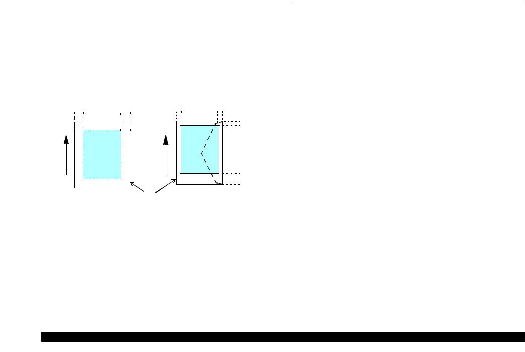
1.2.6 Printing Area
The printing area of this printer is shown below.
Table 1-8. Printing Area (Margins)
Paper Size |
|
Margin |
|
||
Left (LM) |
Right (RM) |
Top (TM) |
Bottom (BM) |
||
|
|||||
|
|
|
|
|
|
Any size of cut sheet |
3 mm |
3 mm |
3 mm |
3 mm* |
|
|
|
|
|
|
|
Envelope |
5 mm |
5 mm |
3 mm |
20 mm |
|
|
|
|
|
|
|
Note* : The bottom margin becomes 16mm when duplex printing is performed using plain paper.
|
Cut Sheet |
|
Envelope |
LM |
RM |
LM |
RM |
DirectionFeed |
Print Area |
DirectionFeed |
TM |
|
TM |
|
Print Area |
|
|
|
|
Paper |
|
Paper |
|
|
BM |
|
BM |
|
|
|
|
|
|
Paper Size |
|
Figure 1-2. Printing Area
1.3 Interface
The printer has a USB and network interfaces of the following specifications.
1.3.1 USB Interface
A USB interface is provided for connecting with a PC. The specifications are as follows.
Table 1-9. USB Interface Specifications
Item |
Specifications |
Compatible standards |
• Universal Serial Bus Specifications Revision 2.0 |
• Universal Serial Bus Device Class Definition for Printing |
|
|
Devices Version 1.1 |
Transfer rate |
480 Mbps (High Speed) |
|
|
Data format |
NRZIt |
|
|
Compatible connector |
USB Series B |
|
|
Max. cable length |
2 m or less |
|
|
1.3.2 Network Interface (B-500DN/B-508DN/B-310N/B- 318N/B-510DN/B-518DN only)
B-500DN/B-508DN/B-310N/B-318N/B-510DN/B-518DN incorporates a print server. This allows the user to use the printer via a wired LAN. The network interface specifications are as follows.
Table 1-10. Wired LAN (B-500DN/B-508DN/B-310N/B-318N/B-510DN/B-518DN)
Item |
Specifications |
Communication mode |
100BASE-TX/10BASE-T |
|
|
Port type |
Selectable from Auto, MDI, and MDI-X. |
|
|
Table 1-11. Wired LAN Settings (B-500DN/B-508DN/B-310N/B-318N/B-510DN/B-518DN)
Setting on the printer |
Setting on the destination |
|
Auto |
10Base-T or 100Base-TX is automatically selected by the |
|
hardware. |
||
|
||
|
|
|
10Base-T Half Duplex |
Fixed to 10Base-T and half-duplex communication mode. |
|
|
|
|
10Base-T Full Duplex |
Fixed to 10Base-T and full-duplex communication mode. |
|
|
|
|
100Base-TX Half Duplex |
Fixed to 100Base-TX and half-duplex communication mode. |
|
|
|
|
100Base-TX Full Duplex |
Fixed to 100Base-TX and full-duplex communication mode. |
|
|
|
PRODUCT DESCRIPTION |
Interface |
19 |
Confidential

EPSON B-300/B-308/B-500DN/B-508DN/B-310N/B-318N/B-510DN/B-518DN |
Revision E |
1.4 General Specifications
1.4.1 Electrical Specifications
Table 1-12. Power Supply Specifications
|
|
|
B-300/B-308 |
B-500DN/B-508DN |
B-310N/B-318N/ |
||||||
|
Item |
|
B-510DN/B-518DN |
||||||||
|
|
|
|
|
|
|
|
||||
|
|
|
100-120V 220-240V 100-120V 220-240V 100-120V 220-240V |
||||||||
|
|
|
|
|
|
|
|
||||
|
Rated power supply |
100-120 |
220-240 |
100-120 |
220-240 |
100-120 |
220-240 |
||||
|
|||||||||||
|
voltage |
|
VAC |
|
VAC |
VAC |
|
VAC |
VAC |
|
VAC |
|
|
|
|
|
|
|
|
|
|
|
|
|
Input voltage range |
90-132 |
|
198-264 |
90-132 |
|
198-264 |
90-132 |
|
198-264 |
|
|
|
|
|
||||||||
|
VAC |
|
VAC |
VAC |
|
VAC |
VAC |
|
VAC |
||
|
|
|
|
|
|
||||||
|
|
|
|
|
|
|
|
|
|
|
|
|
Rated current |
|
0.7 A |
|
0.4 A |
0.7 A |
|
0.4 A |
0.7 A |
|
0.7 A |
|
|
|
|
|
|||||||
|
|
|
|
|
|
|
|
|
|
|
|
|
Rated frequency |
|
50 - 60 Hz |
50 |
- 60 Hz |
50 |
- 60 Hz |
||||
|
|
||||||||||
|
|
|
|
|
|
|
|
|
|
|
|
|
Input frequency |
50 Hz |
49 - 51 Hz |
49 |
- 51 Hz |
49 |
- 51 Hz |
||||
|
range |
|
|
|
|
|
|
|
|
|
|
|
60 Hz |
58.8 - 61.2 Hz |
58.8 |
- 61.2 Hz |
58.8 |
- 61.2 Hz |
|||||
|
|||||||||||
|
|
|
|
|
|
|
|
|
|
|
|
|
Power |
Printing |
30 W |
32 W |
30 W |
||||||
|
|||||||||||
|
|
|
|
|
|
|
|
|
|
|
|
|
Ready |
|
6 W |
|
8 W |
6.5 W |
|
7.0 W |
|||
|
consumption |
|
|
|
|||||||
|
|
|
|
|
|
|
|
|
|
|
|
|
Sleep |
3 W |
|
3.5 W |
4.5 W |
|
5 W |
3.5 W |
|||
|
|
|
|
||||||||
|
*The values are |
mode |
|
|
|||||||
|
|
|
|
|
|
|
|
|
|
||
|
approximate. |
Power |
0.3 W |
|
0.6 W |
0.3 W |
|
0.6 W |
0.2 W |
|
0.4 W |
|
|
off |
|
|
|
||||||
|
|
|
|
|
|
|
|
|
|
|
|
|
|
|
|
|
|
|
|
|
|
|
|
Note 1: B-300/B-308/B-310N/B-318N/B-510DN/B-518DN conform to Energy Star.
2:When the printer is not operated for more than three minutes, the printer goes into the power save mode within five minutes.
1.4.2 Safety Approvals (Safety standards/EMI)
Taiwan |
CNS13438 Class B |
|
CNS14336 |
EU |
EN55022 Class B |
|
EN55024 |
|
EN61000-3-2, EN61000-3-3 |
EU/ Germany |
EN60950-1 |
Russia |
GOST-R (IEC60950-1, CISPR 22) |
Singapore |
IEC60950-1 |
Korea |
K60950-1 |
|
KN22 Class B |
|
K61000-4-2/-3/-4/-5/-6/-11 |
PRODUCT DESCRIPTION |
General Specifications |
20 |
|
|
Confidential |
EPSON B-300/B-308/B-500DN/B-508DN/B-310N/B-318N/B-510DN/B-518DN |
Revision E |
1.4.3 Environmental Conditions
Table 1-13. Environmental Conditions
Condition |
Temperature*1 |
Humidity*1,2 |
Shock |
Vibration |
Operating |
10 to 35oC |
20 to 80% |
1G |
0.15G (10 to 55Hz) |
(50 to 95oF) |
(1 msec or less) |
|||
Unpacked |
-20 to 40oC*3 |
5 to 85% |
2G |
0.50G (10 to 55Hz) |
(-4 to 104oF) |
(2 msec or less) |
Note *1: The combined Temperature and Humidity conditions must be within the blue-shaded range in Figure 1-3.
*2: No condensation
*3: Must be less than 1 month at 40oC.
|
90 |
|
|
|
|
|
|
|
|
|
|
|
|
|
|
|
|
|
80 |
|
|
|
|
|
|
|
|
|
|
|
|
|
|
|
|
|
70 |
|
|
|
|
|
|
|
|
|
|
|
|
|
|
||
Humidity (%) |
60 |
|
|
|
|
|
|
|
|
|
|
|
|
|
|||
50 |
|
|
|
|
|
|
|
|
|
|
|
|
|
|
|
||
|
|
|
|
|
|
|
|
|
|
40 |
|
|
|
|
|
|
|
|
|
|
|
|
|
|||
|
30 |
|
|
|
|
|
|
|
|
|
|
|
|
|
|
||
|
20 |
|
|
|
|
|
|
|
|
|
|
|
|
|
|
|
|
|
|
|
|
|
|
|
|
|
|
|
|
|
|
|
|
|
|
|
10 |
20 |
27 |
30 |
35 |
40 |
|
|
Temperature (oC) |
|
|
||
|
Figure 1-3. Temperature/Humidity Range |
|
||||
|
|
|||||
CAUTION |
When not using the printer, make sure the Printhead is covered |
|||||
|
with the cap and the ink cartridge is installed. |
|
||||
If the Printhead is not covered with the cap when the printer is
off, turn on the printer with the ink cartridge installed, make sure the Printhead is covered with the cap, and then turn the printer off.
1.4.4 Durability
Item |
Specifications |
|
|
Until any one of the following conditions is met. Printer mechanism life • 100,000 sheets
• Five years
PRODUCT DESCRIPTION |
General Specifications |
21 |
|
|
Confidential |
EPSON B-300/B-308/B-500DN/B-508DN/B-310N/B-318N/B-510DN/B-518DN |
Revision E |
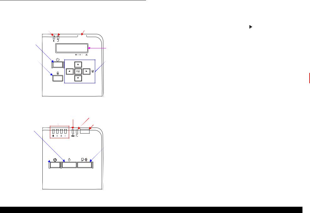
1.5 Control Panel
1.5.1 Operation Buttons
The operation buttons, LEDs, and LCD (B-500DN/B-508DN/B-310N/B-318N/B- 510DN/B-518DN only) are shown below.
Ink LED Paper LED |
Power LED |
||||||
|
|
|
|
|
|
|
|
|
|
|
|
|
|
|
|
Power button
LCD
Cancel button |
OK button, Arrow buttons |
|
Figure 1-4. Control Panel (B-500DN/B-508DN/B-310N/B-318N/B-510DN/B-518DN)
Ink LEDs |
Ink LED |
Paper LED |
(Black, Cyan, Magenta, Yellow) |
|
Power LED |
|
|
|
Ink button |
|
|
Power button |
|
Paper button |
Figure 1-5. Control Panel (B-300/B-308)
Table 1-14. Operation Buttons, LED, LCD (B-500DN/B-508DN/B-310N/B-318N/B-510DN/B-518DN)
Buttons/LEDs/LCD |
|
Function |
|
|
|
|
|
|
|
|
Power |
Turns the power ON/OFF. |
|
|
|
|
|
|
|
|
OK |
Clears an error and accepts a selected menu setting. |
|
|
Button |
|
|
|
|
Arrows |
• |
Displays the menu screen. ( button) |
|
|
|
• |
Goes to the next item in the menu. |
|
|
|
|
|
||
|
|
|
|
|
|
Cancel |
Cancels the menu selection, or cancels a job. |
|
|
|
|
|
|
|
|
Power |
Indicates the power-on status, or operating status. |
|
|
LED*1 |
|
|
|
|
Ink |
Indicates an error status regarding to ink and maintenance box. |
|
||
|
Paper |
Indicates an error status regarding to paper. |
|
|
|
|
|
|
|
LCD*1 |
|
Indicates the printer status, error, and menu screen. |
|
|
|
Indicates fatal error code*2 |
|
||
|
|
|
||
|
|
|
|
|
Note *1: See Table 1-16 for more details about the LEDs and LCD. *2: B-310N/B-318N/B-510DN/B-518DN only
Table 1-15. Operation buttons, LED (B-300/B-308)
Operation buttons/LEDs |
Function |
||
|
|
|
|
|
Power |
Turns the power ON/OFF. |
|
|
|
|
|
Button |
Ink |
Runs a cleaning. |
|
|
|
|
|
|
Paper |
Feeds / ejects paper |
|
|
|
|
|
|
Power |
Indicates the power-on status, or operating status. |
|
|
|
|
|
|
Ink |
Indicates an error status regarding to ink and maintenance box. |
|
|
|
|
|
|
|
Black |
Indicates an error status of black ink. |
|
|
|
|
LED* |
Ink |
Cyan |
Indicates an error status of cyan ink. |
|
Magenta |
Indicates an error status of magenta ink. |
|
|
|
||
|
|
|
|
|
|
Yellow |
Indicates an error status of yellow ink. |
|
|
|
|
|
Paper |
Indicates an error status of paper. |
|
|
|
|
|
Note * : |
See Table 1-16 for more details about LEDs. |
||
PRODUCT DESCRIPTION |
Control Panel |
22 |
Confidential

EPSON B-300/B-308/B-500DN/B-508DN/B-310N/B-318N/B-510DN/B-518DN Revision E
1.5.2 LEDs and LCD Indications
Table 1-16. LEDs and LCD Indications
|
Status |
|
LEDs |
|
|
LCD Message*2 |
|
Priority |
||
|
Power LED |
Ink LED |
Paper LED |
Ink LEDs*1 |
|
|
B-300/B-308/ |
B-310N/B-318N/ |
||
|
|
|
|
|
B-500DN/B-510DN B-510DN/B-518DN |
|||||
|
|
|
|
|
|
|
|
|
||
|
|
|
|
|
|
|
|
|
|
|
|
Powering ON*3 |
Flash |
--- |
--- |
--- |
PLEASE WAIT |
|
--- |
--- |
|
|
|
|||||||||
|
Printing is available*3 |
ON |
--- |
--- |
--- |
READY |
|
|
--- |
22 |
|
Powering ON*4 |
Flash / ON*5 |
--- |
--- |
--- |
PLEASE WAIT |
|
21 |
--- |
|
|
Switching monochrome priority mode on/off*3 |
OFF |
Flash at high speed |
Flash at high speed 2 |
--- |
--- |
|
|
--- |
21 |
|
Maintenance call |
--- |
--- |
--- |
Flash 2 |
NOZZLE MAINT ERROR SEE GUIDE |
|
20 |
20 |
|
|
|
|
|
|
|
|
|
|
|
|
|
Ink level low |
--- |
Flash |
--- |
Flash *6 |
REPLACE INK CARTRIDGE |
ICON |
19 |
19 |
|
|
Maintenance box near full |
--- |
Flash |
--- |
--- |
REPLACE MAINT |
ICON |
18 |
18 |
|
|
Processing data |
Flash |
--- |
--- |
--- |
--- |
|
|
17 |
17 |
|
|
|
|
|
|
|
|
|
|
|
|
Feeding / ejecting paper |
Flash |
--- |
--- |
--- |
--- |
|
|
16 |
16 |
|
Executing ink sequence |
Flash |
--- |
--- |
--- |
--- |
|
|
15 |
15 |
|
|
|
|
|
|
|
|
|
|
|
|
Printer cover open error |
--- |
Flash 2 |
Flash 2 |
--- |
CLOSE PRINTER COVER |
|
14 |
14 |
|
|
|
|
|
|
|
|
|
|
|
|
|
Paper out error |
--- |
--- |
ON |
--- |
(Front) SET PAPER IN CASSETTE |
OK |
13 |
13 |
|
|
(Rear) SET PAPER IN AUTO FEEDER |
OK |
||||||||
|
|
|
|
|
|
|
|
|||
|
|
|
|
|
|
|
|
|
|
|
|
No duplex unit error |
--- |
--- |
Flash 2 |
--- |
SET DUPLEX UNIT |
|
12 |
12 |
|
|
|
|||||||||
|
Multi-feed error |
--- |
--- |
ON |
--- |
DOUBLE FEED JAM REMOVE PAPER |
OK |
11 |
11 |
|
|
|
|
|
|
|
|
|
|
|
|
|
Ink cartridge CSIC error |
--- |
ON |
--- |
ON*6 |
REPLACE INK CARTRIDGE |
ICON*7 |
10 |
10 |
|
|
No ink cartridge or no ink error |
--- |
ON |
--- |
ON*6 |
SET INK CARTRIDGE |
ICON*7 |
9 |
9 |
|
|
Maintenance cartridge CSIC error |
--- |
ON |
--- |
--- |
SET MAINT BOX |
ICON*7 |
8 |
8 |
|
|
No maintenance cartridge or no ink error |
--- |
ON |
--- |
--- |
SET MAINT BOX |
ICON*7 |
7 |
7 |
|
|
Ink lock lever open error |
--- |
ON |
--- |
--- |
MOVE INK LEVER DOWN |
ICON*7 |
6 |
6 |
|
|
SET INK CARTRIDGE*8 |
ICON*7 |
||||||||
|
|
|
|
|
|
|
|
|||
|
Maintenance box cover open error |
--- |
ON |
--- |
--- |
CLOSE MAINT BOX COVER |
ICON*7 |
5 |
5 |
|
|
SET MAINT BOX*9 |
ICON*7 |
||||||||
|
|
|
|
|
|
|
|
|||
|
|
|
|
|
|
(Front) |
REMOVE JAMMED PAPER |
OK |
|
|
|
Paper jam |
--- |
--- |
Flash |
--- |
(Rear) |
REMOVE JAMMED PAPER |
OK |
4 |
4 |
|
||||||||||
|
|
|
|
|
|
(Duplex) DUPLEX UNIT JAM REMOVE PAPER |
OK |
|
|
|
|
|
|
|
|
|
|
|
|
|
|
|
Fatal error |
OFF |
Flash at high speed |
Flash at high speed |
--- |
PRINTER ERROR RESTART PRINTER |
|
3 |
3 |
|
|
XXXX*10 |
|
||||||||
|
|
|
|
|
|
|
|
|
||
|
Service call |
OFF |
Alternate Flash 2 |
Alternate Flash 1 |
--- |
SERVICE CALL SEE GUIDE |
|
2 |
2 |
|
|
Power OFF |
Flash at high speed |
OFF |
OFF |
OFF |
POWER OFF |
|
1 |
1 |
|
|
|
|
|
|
|
|
|
|
|
|
|
Reset request*11 |
ON*4 / Flash *3 |
ON*4/ --- *3 |
ON*4/ --- *3 |
ON |
--- |
|
|
--- |
--- |
|
|
|
|
|
|
|
|
|
|
|
Note *1: |
B-300/B-308 only |
|
Note : ---: |
No change |
|
*2: |
B-500DN/B-508DN/B-310N/B-318N/B-510DN/B-518DN only |
|
Flash: |
Repeats ON for 1.25 seconds, OFF for 1.25 seconds |
|
*3: |
B-310N/B-318N/B-510DN/B-518DN only |
|
Flash 2: |
Repeats ON for 0.5 second, OFF for 0.5 second, ON for 0.5 second |
|
*4: |
B-300/B-308/B-500DN/B-508DN only |
|
|
and OFF for 1.0 second. |
|
*5: |
B-300/B-308 power LED flashes, and that of B-500DN/B-508DN turns ON. |
|
Flash at high speed: |
Repeats ON for 0.5 second, OFF for 0.5 second |
|
*6: |
The corresponding LED flashes or lights. |
|
Flash at high speed 2: Repeats OFF for 0.5 second, ON for 0.5 second |
||
|
Alternate Flash1: |
Same as the above Flash. |
|||
*7: |
See “Table 1-17. LCD Icon Display (B-500DN/B-508DN/B-310N/B-318N/B-510DN/B-518DN only)” on |
||||
Alternate Flash1: |
Repeats OFF for 1.25 seconds, ON for 1.25 seconds |
||||
|
page24 for the icons shape. |
|
|||
|
|
|
|
||
*8: |
B-500DN/B-508DN only. The LED turns ON when the ink lever is moved to its upper position after an error occurs. |
|
|
||
*9: |
The LED turns ON when the maintenance cover is opened after an error occurs. |
|
|
|
|
*10: |
The fatal error code is indicated only for B-310N/B-318N/B-510DN/B-518DN. See “3.3.2 Fatal Error” on |
|
|
||
|
page48 for the details. |
|
|
|
|
*11: |
When a reset request occurs, the LED lights for 0.2 seconds. |
|
|
|
|
|
|
|
|||
PRODUCT DESCRIPTION |
Control Panel |
23 |
|||
Confidential
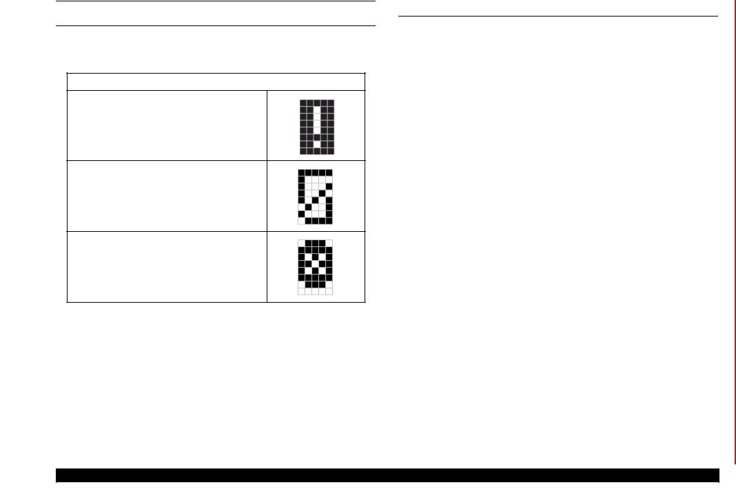
EPSON B-300/B-308/B-500DN/B-508DN/B-310N/B-318N/B-510DN/B-518DN |
Revision E |
LCD ICON DISPLAY (B-500DN/B-508DN/B-310N/B-318N/B-510DN/B-518DN)
The following icons appear on the LCD according to the printer status.
Table 1-17. LCD Icon Display (B-500DN/B-508DN/B-310N/B-318N/B-510DN/B-518DN only)
Printer Status |
Icon |
|
|
•Ink level low
•Maintenance box near full
•No ink
•Maintenance box full
•Ink cartridge CSIC error
•No ink cartridge
1.6 Various Settings
1.6.1 Panel Operation
1.6.1.1Menu Configuration (B-500DN/B-508DN/B-310N/B-318N/ B-510DN/B-518DN only)
The setting screen is displayed by pressing the right arrow button on ready mode (the LCD display is “READY” or “POWER SAVE”). The following explains the menu structure and the outline of the menu functions.
Table 1-18. Menu Configuration
|
Menu |
Description |
|
|
PRINTER |
LANGUAGE |
Selects the language displayed on the LCD. |
|
|
|
|
|
USB |
|
|
|
SETTING |
Selects the printer control language for the port. |
|
|
|
||
|
Network |
||
|
|
|
|
|
|
|
|
|
|
NOZZLE CHECK |
Prints a printhead nozzle check pattern. |
|
|
|
|
|
|
STATUS SHEET |
Prints a status sheet for current printer status. (See |
|
TEST PRINT |
Figure 1-8.) |
|
|
|
||
|
|
|
|
|
|
NETWORK SHEET |
Prints a network status sheet for current settings of the |
|
|
network interface. (See Figure 1-9 and Figure 1-10.) |
|
|
|
|
|
|
PRINTER |
VERSION |
Displays the firmware version. |
|
|
|
|
|
MAINTENANCE |
Displays the rough estimate of the remaining |
|
|
STATUS |
||
|
BOX |
capacity of the Maintenance Box. |
|
|
|
||
|
|
|
|
|
|
HEAD ALIGNMENT |
Adjusts the printhead alignment. |
|
|
|
|
|
|
CLEANING |
Runs a printhead cleaning. |
|
|
|
|
MENU |
|
CLEANING SHEET |
Runs a cleaning for the rollers inside the printer. |
|
|
|
|
|
|
CONTRAST ADJ. |
Adjusts the contrast of the LCD. |
|
|
|
|
|
MAINTENANCE |
|
Changes the setting of the AID detection cleaning. |
|
AUTO CLEANING |
(See “1.6.2.1 AID Detection Cleaning (B-310N/B- |
|
|
|
|
318N/B-510DN/B-518DN only)” on page26.) |
|
|
|
|
|
|
|
Changes the setting of the low speed mode (MPBF |
|
|
LOW SPEED MODE |
priority mode). (See “1.6.3 Low Speed Mode (MPBF |
|
|
Priority Mode) (B-310N/B-318N/B-510DN/B- |
|
|
|
|
|
|
|
|
518DN only)” on page28.) |
|
|
|
|
|
NETWORK |
NETWORK SETUP |
Selects the method to configure the network settings. |
|
SETTING |
||
|
|
|
|
|
|
|
|
|
|
PASSWORD SET. |
Sets a password. |
|
|
(See “ Password setting” on page26.) |
|
|
PASSWORD |
|
|
|
|
|
|
|
|
Changes the setting of the panel operation lock. (See |
|
|
MENU* |
LOCK SETTING |
|
|
|
“1.6.1.2 Panel Operation Lock Setting (B-310N/B- |
|
|
|
|
318N/B-510DN/B-518DN only)” on page25.) |
|
Note* : B-310N/B-318N/B-510DN/B-518DN only. |
|
|
|
|
PRODUCT DESCRIPTION |
Various Settings |
24 |
Confidential

EPSON B-300/B-308/B-500DN/B-508DN/B-310N/B-318N/B-510DN/B-518DN |
Revision E |
1.6.1.2 Panel Operation Lock Setting (B-310N/B-318N/B-510DN/B-518DN only)
For B-310N/B-318N/B-510DN/B-518DN, the panel operation can be locked after setting the password. (See Password setting (p.26).)
Table 1-19. Panel Operation Lock Setting
ON |
OFF |
On ready mode (the LCD display is |
Entering the password is not required to go to |
“READY” or “POWER SAVE”), the |
the setting screen even the password is |
password is required to go to the setting |
registered. |
screen. |
|
If the correct password is entered, goes to |
|
the setting screen. |
|
“WRONG PASSWORD” is displayed if a |
|
wrong password is entered, and the access |
|
to the setting screen is denied. After the |
|
error is displayed for a while, the printer |
|
returns to the ready mode (the LCD |
|
display is “READY”). |
|
Error reset and powering off are still |
|
available. |
|
|
|
Note : The lock/unlock condition is not printed on the printed sheets such as the nozzle check pattern or the status sheets.
Setting Method
1.Perform Password setting (p.26) by operating the control panel.
2.Select “LOCK SETTING” from “MENU” (Table 1-18), and select “ON” or “OFF”.
Note 1: If the cancel button is pressed during its setting or when “ON” is set, the printer returns to the ready mode (the LCD display is “READY” or “POWER SAVE”).
2:After “ON” is set, the panel operation is locked immediately.
3:When “OFF” is set, the display returns to “PASSWORD MENU”.
4:Once the password is set, the panel operation can be locked by performing Step 2.
Resetting the Password/Unlocking the Panel Operation Lock
If you need to reset the password or unlock the panel operation because of forgetting the password and such, follow the steps below to reset them.
CAUTION |
Do not disclose the following method to the end users. |
|
|
||
|
|
|
Resetting/Unlocking method
1.Press and hold the right arrow button, left arrow button and OK button and then turn on the printer.
2.Release all the buttons after the printer is turned on.
Settings after reset |
|
• Password: |
Not set |
• Panel operation lock: |
OFF |
PRODUCT DESCRIPTION |
Various Settings |
25 |
Confidential
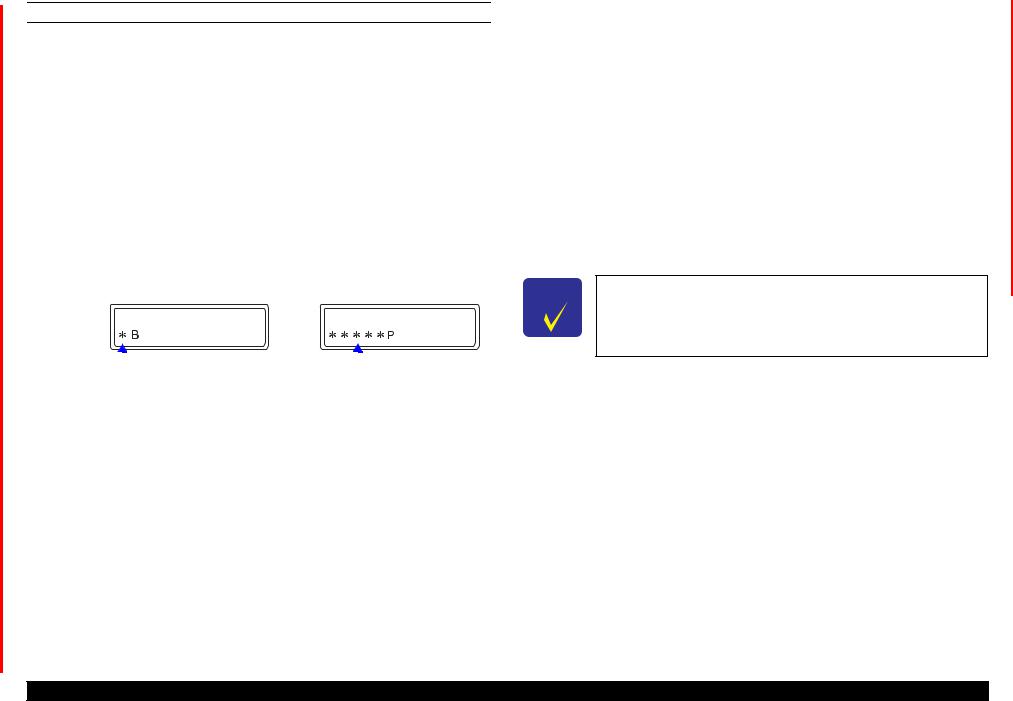
EPSON B-300/B-308/B-500DN/B-508DN/B-310N/B-318N/B-510DN/B-518DN |
Revision E |
PASSWORD SETTING
Select the “PASSWORD SET.” from the “MENU” (Table 1-18) to set or change the password.
|
|
|
|
|
|
|
|
|
|
|
Table 1-20. Password Setting |
|||||||||||
|
|
|
|
|
|
|
|
|
|
|
|
|
|
|
|
|
|
|
|
|
|
|
Item |
|
|
|
|
|
|
|
|
|
|
|
Description |
||||||||||
|
|
|
|
|
|
|
|
|
|
|
|
|
|
|
|
|
|
|
|
|
|
|
Digit of the |
Within 1 to 8 |
|
|
|
|
|
|
|
|
|
|
|||||||||||
password |
|
|
|
|
|
|
|
|
|
|
||||||||||||
|
|
|
|
|
|
|
|
|
|
|
|
|
|
|
|
|
|
|
|
|
||
|
|
|
|
|
|
|
|
|
|
|
|
|
|
|
|
|
|
|
|
|
|
|
Available |
Space,!”#$%&'()*+,-./, 0 to 9, ;:<=>?@, A to Z, [\]^_`, a to z, {|}~ |
|||||||||||||||||||||
characters |
||||||||||||||||||||||
|
|
|
|
|
|
|
|
|
|
|
|
|
|
|
|
|
|
|
|
|
||
|
|
|
|
|
|
|
|
|
|
|
|
|
|
|
|
|
|
|
|
|
||
|
Select the characters with the up and down arrow buttons, and move to the next |
|||||||||||||||||||||
|
digit with the right arrow button. When pressing the right arrow button, the input |
|||||||||||||||||||||
|
character is masked with “* (asterisk)”. The characters which are masked with “* |
|||||||||||||||||||||
|
(asterisk)” will be saved on the EEPROM as the password after pressing the OK |
|||||||||||||||||||||
|
button. To set the password, entries are required three time according to the |
|||||||||||||||||||||
|
instruction displayed on the LCD (“CURRENT PASSWORD”, “NEW |
|||||||||||||||||||||
Method |
PASSWORD” and “REENTER NEW PASSWORD”). |
|||||||||||||||||||||
|
|
|
|
|
|
|
|
|
|
|
|
|
|
|
|
|
|
|
|
|
||
|
|
|
NEW PASSWORD |
|
|
NEW PASSWORD |
||||||||||||||||
|
|
|
|
|
|
|
|
|
|
|
|
|
|
|
|
|
|
|
|
|
||
|
|
|
|
|
|
|
|
|
|
|
|
|
|
|
|
|
|
|
|
|
||
|
|
|
|
|
|
|
|
|
|
|
|
|
|
|
|
|
|
|||||
|
|
|
|
|
|
|
An input character changes to “* (asterisk)” each |
time it is accepted. |
|
|||||||||||||
|
|
|
|
|
|
|
|
|
|
|
|
|
|
|
|
|
|
|
|
|
|
|
|
|
|
|
|
|
|
|
|
|
|
|
|
|
|
|
|
|
|
|
|
|
|
Note 1: The password is not set when shipping from the factory.
2:If there is a wrong entry to “CURRENT PASSWORD” or “REENTER NEW PASSWORD”, “WRONG PASSWORD” is displayed and then returned to the “PASSWORD MENU” screen.
3:After the password is entered in “REENTER NEW PASSWORD”, the change is completed and the display returns to “PASSWORD MENU”.
4:The password is stored on the EEPROM (not NMI area), and kept even the power is off.
1.6.1.3 Forced Power OFF
For B-300/B-308/B-500DN/B-508DN/B-310N/B-318N/B-510DN/B-518DN, the power can be turned off forcibly by the following panel operation. If the power is turned off forcibly, the same process of the normal power-off is executed.
1.6.2 AID Function Setting
1.6.2.1AID Detection Cleaning (B-310N/B-318N/B-510DN/B-518DN only)
For B-310N/B-318N/B-510DN/B-518DN, the AID detection cleaning can be set on/off.
Table 1-21. AID Detection Cleaning
ON |
OFF |
Automatically checks the printhead nozzles |
The nozzle check with the AID function and |
with AID function and carries out printhead |
auto cleaning is not carried out. Carries out |
cleaning if they are clogged. |
the printhead cleaning only when selecting |
|
“CLEANING” from “MENU” (Table 1-18). |
|
|
Setting Method
Select “AUTO CLEANING” from “MENU” (Table 1-18), and select “ON” or “OFF”.
CHECK This setting is not available for B-300/B-308/B-500DN/B-508DN.
POINT
Operation Method
1.Press and hold the power button and the OK button for seven seconds or more.
2.Release the power button after the printer is turned off.
PRODUCT DESCRIPTION |
Various Settings |
26 |
Confidential
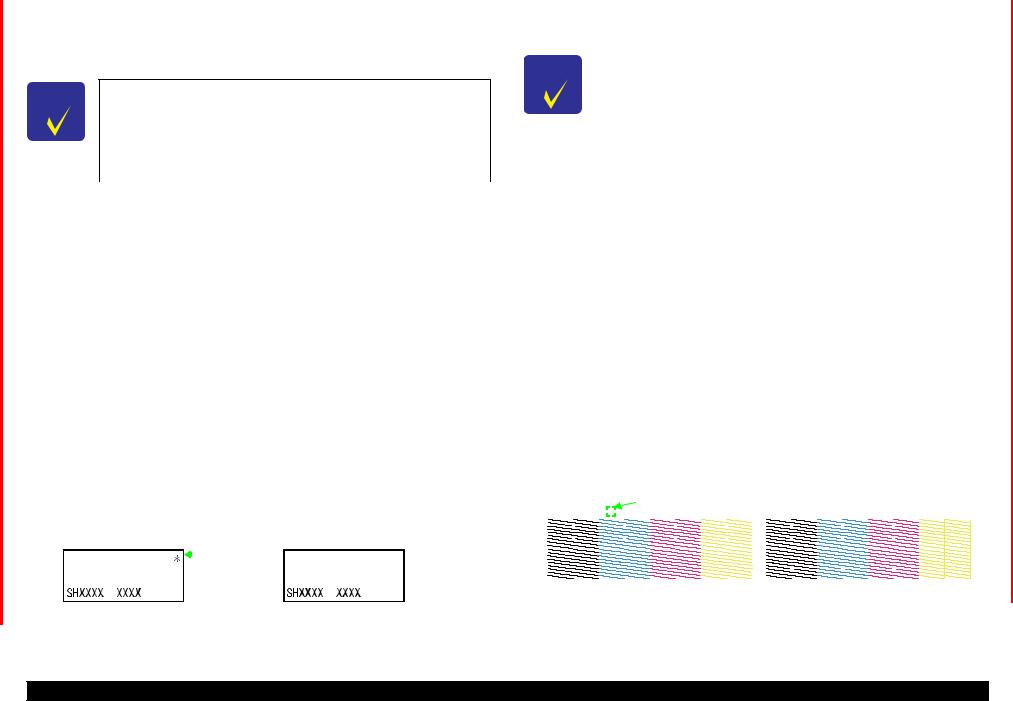
EPSON B-300/B-308/B-500DN/B-508DN/B-310N/B-318N/B-510DN/B-518DN |
Revision E |
1.6.2.2 AID High Quality Mode/Dot Missing Tolerance Mode
For B-310N/B-318N/B-510DN/B-518DN, the AID high quality mode or the dot missing tolerance mode can be selected by the special operation at power-on when the AID detection cleaning is on.
CHECK For B-300/B-308/B-500DN/B-508DN, this setting is available only POINT when the firmware is the following version or later. However, the setting mode is fixed to “dot missing tolerance mode” for B-300/B-
308.
|
• B-300/B-308: |
SH1998 |
|
|
• B-500DN/B-508DN: SL1998 |
|
|
|
|
|
|
|
Table 1-22. Mode |
|
|
|
|
|
|
AID High Quality Mode |
Dot Missing Tolerance Mode |
|
|
|
|
|
|
Checks the nozzle clogging and carries out |
If two or less nozzles and no neighboring |
|
|
appropriate cleaning. |
nozzles are clogged, the cleaning is not |
|
|
|
|
carried out. For nozzle clogging detection in |
|
|
|
the other cases, the cleaning is carried out. |
|
|
|
|
|
Setting Change Method
Follow the procedure below to switch the cleaning mode between the AID high quality mode and dot missing tolerance mode.
1.Press and hold the power button and the OK button simultaneously when the power is off.
2.Release the all buttons when the power is turned on.
How to Check the Current Mode
Select “VERSION” from “MENU” (see Table 1-18), and check the upper right corner of the LCD. If “*(asterisk)” is displayed, the printer is the AID high quality mode. The mode status cannot be confirmed from the printed sheets such as the nozzle check pattern or the status sheets.
AID high quality mode |
|
|
|
|
Dot missing tolerance mode |
||||
|
|
|
|
|
|
|
|
|
|
VERSION |
|
|
|
|
|
|
* (asterisk) |
|
VERSION |
|
|
|
|
|
is indicated |
|
|||
|
|
|
|
||||||
|
|
|
|
|
|
|
|
|
|
Figure 1-6. How to Check AID High Quality Mode/Dot Missing Tolerance Mode
1.6.2.3 Monochrome Priority Mode
For B-310N/B-318N/B-510DN/B-518DN, “monochrome priority mode” with the AID function is available to check the nozzle clogging only for nozzles of black ink.
CHECK |
This setting is available when the firmware is the following version |
|
|
POINT |
or later for B-300/B-308/B-500DN/B-508DN. |
|
|
|
• B-300/B-308: |
SH1998 |
|
|
• B-500DN/B-508DN: SL1998 |
|
|
|
|
|
|
|
Table 1-23. Monochrome Priority Mode |
|
|
|
|
|
|
|
Valid |
Invalid |
|
|
|
|
|
Checks the nozzle clogging only for nozzles |
Checks all the nozzles and carries out |
|
|
of black ink, and carries out printhead |
printhead cleaning. |
|
|
cleaning. |
|
|
|
|
|
|
|
Note : The monochrome priority mode is invalid as the default.
Setting Method
Follow the procedure below to switch between valid and invalid.
1.Press and hold the power button and the up arrow button simultaneously.
2.After the power LED flashes, release the power button and the up arrow button, and press and hold the down arrow button immediately.
3.When the ink LED and the paper LED starts flashing alternately, release the down arrow button.
How to Check the Current Mode
When the monochrome priority mode is on, “* (asterisk)” is printed on the nozzle check pattern as shown below. The mode status (valid or invalid) cannot be confirmed on the LCD.
Monochrome priority mode is on |
|
|
|
|
Monochrome priority mode is off |
|||||||||||||||||||||
|
|
|
|
|
|
|
|
|
|
|
|
|
|
|
|
|
|
|
|
|
||||||
|
|
|
|
|
|
* (asterisk) is |
printed |
|
|
|
|
|
|
|
|
|
|
|
|
|
||||||
xxxxxx xxxxxxxx |
|
|
xxxxxx xxxxxxxx |
|||||||||||||||||||||||
|
|
|
|
|
|
|
|
|
||||||||||||||||||
|
|
|
|
|
|
|
|
|
|
|
|
|
|
|
|
|
|
|
|
|
|
|
|
|
|
|
|
|
|
|
|
|
|
|
|
|
|
|
|
|
|
|
|
|
|
|
|
|
|
|
|
|
|
|
|
|
|
|
|
|
|
|
|
|
|
|
|
|
|
|
|
|
|
|
|
|
|
|
|
|
|
|
|
|
|
|
|
|
|
|
|
|
|
|
|
|
|
|
|
|
|
|
|
|
|
|
|
|
|
|
|
|
|
|
|
|
|
|
|
|
|
|
|
|
|
|
|
|
|
|
|
|
|
|
|
|
|
|
|
|
|
|
|
|
|
|
|
|
|
|
|
|
|
|
|
|
|
|
|
|
|
|
|
|
|
|
|
|
|
|
|
|
|
|
|
|
|
|
|
|
|
|
|
|
|
|
|
|
Figure 1-7. How to Check Monochrome Priority Mode
PRODUCT DESCRIPTION |
Various Settings |
27 |
Confidential

EPSON B-300/B-308/B-500DN/B-508DN/B-310N/B-318N/B-510DN/B-518DN |
Revision E |
1.6.3Low Speed Mode (MPBF Priority Mode) (B-310N/B-318N/B-510DN/B-518DN only)
To prevent the troubles (printhead clogging or the like) from occurring due to paper dust caused by the printing-related movement, the low speed mode (MPBF priority mode) is available for B-310N/B-318N/B-510DN/B-518DN.
Table 1-24. Low Speed Mode (MPBF Priority Mode)
ON |
OFF |
The carriage always moves from end to end |
Carries out the normal printing. |
(full-digit drive) for printing. It can decrease |
|
paper dust caused by the printing-related |
|
movement to prevent printing troubles such as |
|
printhead clogging. However, the printing |
|
speed becomes slower. |
|
|
|
Note : The low speed mode is off as the default.
Setting Method
Set by panel operation
Select “LOW SPEED MODE” from “MENU” (Table 1-18), and select “ON” or “OFF”.
Note : The setting is stored in the non-volatile memory and kept when the power is off.
Automatic change
If all the following conditions are met, the low speed mode (MPBF priority mode) is turned on even if the setting from the panel is off.
•Stays in ready mode for five to seven minutes.
•More than 100 sheets are printed after the last AID detection.
•Number of accumulated printed sheets is 10 to 400 after the last manual cleaning.
Note1: When the setting is on by the automatic change, the setting is turned off when the ink cartridge cover is opened/closed.
2:The setting made by the automatic change is not saved in the non-volatile memory, therefore, the setting is turned off once the power is off.
1.7 Status Sheet
B-500DN/B-508DN/B-310N/B-318N/B-510DN/B-518DN prints the following printer status sheet when the Printer Status menu is selected. For B-300/B-308, turn it on while holding down the Ink button. B-500DN/B-508DN/B-310N/B-318N/B-510DN/B- 518DN also can print a network status sheet shown on the following pages.
Log Status Sheet |
|
|
|
|
|
|
Printer Name |
|
"model name" |
|
|
|
|
Serial No. |
|
xxxxxxxxxxx |
|
|
|
|
Firmware version |
SHxxxx(SLxxxx) |
|
|
|
||
First Print Time |
yyyy/mm/dd hh:mm |
|
|
|||
Last Print Time |
|
yyyy/mm/dd hh:mm |
|
|
||
Total Pages |
|
000000 |
|
|
|
|
Color Pages |
|
000000 |
|
|
|
|
B/W Pages |
|
000000 |
|
|
|
|
Print of papers |
|
|
|
|
|
|
|
Total |
|
Mono |
|
Color |
|
|
|
|
Simplex |
Duplex |
Simplex |
Duplex |
A4/Letter |
000000 |
000000 |
000000 |
000000 |
000000 |
|
A5 |
000000 |
000000 |
000000 |
000000 |
000000 |
|
A6/HAGAKI |
000000 |
000000 |
000000 |
000000 |
000000 |
|
Envelope |
000000 |
000000 |
000000 |
000000 |
000000 |
|
Others |
000000 |
000000 |
000000 |
000000 |
000000 |
|
Print of mode[pages] |
|
|
|
|
|
|
|
Simplex |
Duplex |
Total |
|
|
|
Mono |
000000 |
000000 |
000000 |
|
|
|
Color |
000000 |
000000 |
000000 |
|
|
|
Total |
000000 |
000000 |
000000 |
|
|
|
Figure 1-8. Printer Status Sheet Sample
PRODUCT DESCRIPTION |
Status Sheet |
28 |
Confidential

EPSON B-300/B-308/B-500DN/B-508DN/B-310N/B-318N/B-510DN/B-518DN |
Revision E |
HHHHHHHHHHHHHHHHHHHHHHHHHHHHHHHHHHHHHH
HH EPSON Network Status Sheet (1/2) HH
HHHHHHHHHHHHHHHHHHHHHHHHHHHHHHHHHHHHHH
<General Information>
Card Type |
EPSON Built-in 10Base-T/100Base-TX Print Server |
SerialNumber |
XXXXXXXXXXXX |
MAC Address |
XX:XX:XX:XX:XX:XX |
Hardware |
XX.XX |
Software |
XX.XX |
Printer Model |
XXXXXXXX |
Time |
YYYY-MM-DD HH:MM:SS GMT+/-HH:MM |
<Ethernet> |
|
Network Status |
Auto(10BASE-T/100BASE-TX, Half/Full Duplex)/ |
|
10BASE-T/100BASE-TX, Half/Full Duplex |
Port Type |
Auto/MDI/MDI-X |
<TCP/IP> |
|
Get IP |
Address Auto/Manual |
IP Address |
XXX.XXX.XXX.XXX |
Subnet Mask |
XXX.XXX.XXX.XXX |
Default Gateway |
XXX.XXX.XXX.XXX |
APIPA |
Enable/Disable |
Set using PING |
Enable/Disable |
Acquisition way of DNS ADDR |
Enable/Disable |
DNS Server Address |
XXX.XXX.XXX.XXX |
|
XXX.XXX.XXX.XXX |
|
XXX.XXX.XXX.XXX |
Acquire Host/Domain name |
Enable/Disable |
Host Name |
XXXXXXXX |
Domain Name |
XXXXXXXX |
Register the NW I/F to DNS |
Enable/Disable |
Register directly to DNS |
Enable/Disable |
Universal Plug and Play |
Enable/Disable |
Device Name |
XXXXXXXX |
Bonjour |
Enable/Disable |
Bonjour Name |
XXXXXXXX.local. |
Bonjour Printer Name |
XXXXXXXX |
Bonjour Service |
XXXXXXXX._printer._tcp.local. |
|
XXXXXXXX._http._tcp.local. |
<Printing Control> |
|
Printing Control |
Enable/Disable |
Access Control |
Allow/Deny |
Access Control List 1 |
XXX.XXX.XXX.XXX - XXX.XXX.XXX.XXX |
Access Control List 2 |
XXX.XXX.XXX.XXX - XXX.XXX.XXX.XXX |
Access Control List 3 |
XXX.XXX.XXX.XXX - XXX.XXX.XXX.XXX |
Access Control List 4 |
XXX.XXX.XXX.XXX - XXX.XXX.XXX.XXX |
Access Control List 5 |
XXX.XXX.XXX.XXX - XXX.XXX.XXX.XXX |
Access Control List 6 |
XXX.XXX.XXX.XXX - XXX.XXX.XXX.XXX |
Access Control List 7 |
XXX.XXX.XXX.XXX - XXX.XXX.XXX.XXX |
Access Control List 8 |
XXX.XXX.XXX.XXX - XXX.XXX.XXX.XXX |
Access Control List 9 |
XXX.XXX.XXX.XXX - XXX.XXX.XXX.XXX |
Access Control List 10 |
XXX.XXX.XXX.XXX - XXX.XXX.XXX.XXX |
Access Control List 11 |
XXX.XXX.XXX.XXX - XXX.XXX.XXX.XXX |
Access Control List 12 |
XXX.XXX.XXX.XXX - XXX.XXX.XXX.XXX |
Access Control List 13 |
XXX.XXX.XXX.XXX - XXX.XXX.XXX.XXX |
Access Control List 14 |
XXX.XXX.XXX.XXX - XXX.XXX.XXX.XXX |
Access Control List 15 |
XXX.XXX.XXX.XXX - XXX.XXX.XXX.XXX |
Access Control List 16 |
XXX.XXX.XXX.XXX - XXX.XXX.XXX.XXX |
HHHHHHHHHHHHHHHHHHHHHHHHHHHHH Printer Model Name HH
Figure 1-9. Network Status Sheet Sample (1)
HHHHHHHHHHHHHHHHHHHHHHHHHHHHHHHHHHHHHH
HH EPSON Network Status Sheet (2/2) HH
HHHHHHHHHHHHHHHHHHHHHHHHHHHHHHHHHHHHHH
<IPP> |
http://xxx.xxx.xxx.xxx |
|
IPP URL |
||
Printer Name |
XXXX |
|
<Port Control> |
Enable/Disable |
|
LPR |
||
Port9100 |
Enable/Disable |
|
Port2501 |
Enable/Disable |
|
FTP |
Enable/Disable |
|
IPP |
Enable/Disable |
|
<SNMP> |
public |
|
Read Community |
|
|
IP Trap 1 |
Enable/Disable |
|
IP Trap Address 1 |
XXX.XXX.XXX.XXX |
|
IP Trap Community 1 |
XXXXXXXX |
|
IP Trap Port 1 |
XXXX |
|
IP Trap 2 |
Enable/Disable |
|
IP Trap Address 2 |
XXX.XXX.XXX.XXX |
|
IP Trap Community 2 |
XXXXXXXX |
|
IP Trap Port 2 |
XXXX |
|
IP Trap 3 |
Enable/Disable |
|
IP Trap Address 3 |
XXX.XXX.XXX.XXX |
|
IP Trap Community 3 |
XXXXXXXX |
|
IP Trap Port 3 |
XXXX |
|
IP Trap 4 |
Enable/Disable |
|
IP Trap Address 4 |
XXX.XXX.XXX.XXX |
|
IP Trap Community 4 |
XXXXXXXX |
|
IP Trap Port 4 |
XXXX |
|
<Time> |
Enable/Disable |
|
Time Server |
||
Time Server Address |
XXX.XXX.XXX.XXX |
|
Synchronize Interval |
XX |
|
Time Difference(GMT+/-HH:MM) |
+/-HH:MM |
|
Time Server Status |
Success/Failure/Synchronize/Invalid |
|
<Idle Timeout> |
XXXX sec |
|
LPR |
|
|
Port9100 |
XXXX sec |
|
IPP |
xxxx sec |
|
<Software Information> |
XX.XX |
XXXXX |
Network FW |
||
EPSONNet Config Web |
XX.XX |
XXXXX |
HHHHHHHHHHHHHHHHHHHHHHHHHHHHH Printer Model Name HH
Figure 1-10. Network Status Sheet Sample (2)
PRODUCT DESCRIPTION |
Status Sheet |
29 |
|
|
Confidential |

C H A P T E R
2
OPERATING PRINCIPLES
Confidential
Loading...