


 Loading...
SERVICE MANUAL
A3 Full Color Laser Printer
EPSON AcuLaser C9100
SEPG04001
PRECAUTIONS
Precautionary notations throughout the text are categorized relative to 1)Personal injury and 2) damage to equipment.
DANGER |
Signals a precaution which, if ignored, could result in serious or fatal personal injury. Great caution should be exercised in |
|
performing procedures preceded by DANGER Headings. |
WARNING |
Signals a precaution which, if ignored, could result in damage to equipment. |
The precautionary measures itemized below should always be observed when performing repair/maintenance procedures.
DANGER
1.ALWAYS DISCONNECT THE PRODUCT FROM THE POWER SOURCE AND PERIPHERAL DEVICES PERFORMING ANY MAINTENANCE OR REPAIR PROCEDURES.
2.NO WORK SHOULD BE PERFORMED ON THE UNIT BY PERSONS UNFAMILIAR WITH BASIC SAFETY MEASURES AS DICTATED FOR ALL ELECTRONICS TECHNICIANS IN THEIR LINE OF WORK.
3.WHEN PERFORMING TESTING AS DICTATED WITHIN THIS MANUAL, DO NOT CONNECT THE UNIT TO A POWER SOURCE UNTIL INSTRUCTED TO DO SO. WHEN THE POWER SUPPLY CABLE MUST BE CONNECTED, USE EXTREME CAUTION IN WORKING ON POWER SUPPLY AND OTHER ELECTRONIC COMPONENTS.
WARNING
1.REPAIRS ON EPSON PRODUCT SHOULD BE PERFORMED ONLY BY AN EPSON CERTIFIED REPAIR TECHNICIAN.
2.MAKE CERTAIN THAT THE SOURCE VOLTAGES IS THE SAME AS THE RATED VOLTAGE, LISTED ON THE SERIAL NUMBER/RATING PLATE. IF THE EPSON PRODUCT HAS A PRIMARY AC RATING DIFFERENT FROM AVAILABLE POWER SOURCE, DO NOT CONNECT IT TO THE POWER SOURCE.
3.ALWAYS VERIFY THAT THE EPSON PRODUCT HAS BEEN DISCONNECTED FROM THE POWER SOURCE BEFORE REMOVING OR REPLACING PRINTED CIRCUIT BOARDS AND/OR INDIVIDUAL CHIPS.
4.IN ORDER TO PROTECT SENSITIVE MICROPROCESSORS AND CIRCUITRY, USE STATIC DISCHARGE EQUIPMENT, SUCH AS ANTISTATIC WRIST STRAPS, WHEN ACCESSING INTERNAL COMPONENTS.
5.REPLACE MALFUNCTIONING COMPONENTS ONLY WITH THOSE COMPONENTS BY THE MANUFACTURE; INTRODUCTION OF SECOND-SOURCE ICs OR OTHER NON-APPROVED COMPONENTS MAY DAMAGE THE PRODUCT AND VOID ANY APPLICABLE EPSON WARRANTY.

About This Manual
This manual describes basic functions, theory of electrical and mechanical operations, maintenance and repair procedures of the printer. The instructions and procedures included herein are intended for the experienced repair technicians, and attention should be given to the precautions on the preceding page.
Manual Configuration
This manual consists of six chapters and Appendix.
CHAPTER 1.PRODUCT DESCRIPTIONS
Provides a general overview and specifications of the product.
CHAPTER 2.OPERATING PRINCIPLES
Describes the theory of electrical and mechanical operations of the product.
CHAPTER 3.TROUBLESHOOTING
Describes the step-by-step procedures for the troubleshooting.
CHAPTER 4.DISASSEMBLY / ASSEMBLY
Describes the step-by-step procedures for disassembling and assembling the product.
CHAPTER 5.ADJUSTMENT
Provides Epson-approved methods for adjustment.
CHAPTER 6.MAINTENANCE
Provides preventive maintenance procedures and the lists of Epson-approved lubricants and adhesives required for servicing the product.
APPENDIX Provides the following additional information for reference:
•Connector pin assignments
•Electric circuit boards components layout
•Electrical circuit boards schematics
•Exploded diagram & Parts List
Symbols Used in this Manual
Various symbols are used throughout this manual either to provide additional information on a specific topic or to warn of possible danger present during a procedure or an action. Be aware of all symbols when they are used, and always read NOTE, CAUTION, or WARNING messages.
Indicates an operating or maintenance procedure, practice or condition that is necessary to keep the product’s quality.
Indicates an operating or maintenance procedure, practice, or condition that, if not strictly observed, could result in damage to, or destruction of, equipment.
May indicate an operating or maintenance procedure, practice or condition that is necessary to accomplish a task efficiently. It may also provide additional information that is related to a specific subject, or comment on the results achieved through a previous action.
Indicates an operating or maintenance procedure, practice or condition that, if not strictly observed, could result in injury or loss of life.

Abbreviation
This manual uses original abbreviations, in addition to general abbreviations.
Typical abbreviations are as follows:
AG .............................. |
Analog Ground |
ADC .......... |
Automatic Density Control |
AG ............................. |
Analog Ground |
APS ....................... |
Auto Paper Select |
ARC ............ |
Auto Registration Control |
ASSY .................................. |
Assembly |
ATS..................... |
Auto Tray Switching |
B . ............................................... |
Black |
Bk . ............................................. |
Black |
BLK . ........................................... |
Black |
BLU ............................................. |
Blue |
BRN ......................................... |
Brown |
BTR ....................... |
Bias Transfer Roll |
C ................................................ |
Cyan |
CLN ....................................... |
Cleaner |
CRU ........ |
Customer Replaceable Unit |
CRUM . ........................... |
CRU Monitor |
DET . ............................... |
Detoner Roll |
DEVE. ................................ |
Developer |
DIAG. . ................................ |
Diagnostic |
DISP . ................................... |
Dispense |
dpi .................................. |
dots per inch |
DTS ................................ |
Detack Saw |
DUP ........................................ |
Duplex |
ESB .................... |
Electro Static Brush |
ESS ..................... |
Electric Subsystem |
F ................................................ |
Front |
FEED ...................................... |
Feeder |
FIP .............. |
Fault Isolation Procedure |
GND . ....................................... |
Ground |
GRN . ......................................... |
Green |
GRY . ........................................... |
Gray |
HT . ...................................... |
Half Tone |
HVPS ...... |
High Voltage Power Supply |
ICDC . Image Count Dispense Control |
|
ID ................................. |
Image Density |
(or Identification) IDT . |
|
................ |
Intermediate Drum Transfer |
INTL . ..................................... |
Interlock |
IOT ................. |
Image Output Terminal |
K . ............................................... |
Black |
L .................................................... |
Left |
L/H . ..................................... |
Left Hand |
LD . ................................... |
Laser diode |
LDD . ................... |
Lightly Doped Drain |
LED ..................... |
Light-emitting diode |
LEF . ......................... |
Long Edge Feed |
LH . ...................................... |
Left Hand |
LV . .................................. |
Low Voltage |
LVPS ....... |
Low Voltage Power Supply |
M ........................................... |
Magenta |
MAG ................................... |
Mag. Roll |
MCU . ................ |
Machine Control Unit |
MOB . ........................... |
Marks On Belt |
MSI ..................... |
Multi Sheet Inserter |
N/P ...................................... |
No Paper |
NVM .................. |
Non Volatile Memory |
OCT ....................... |
Offset Catch Tray |
OEM . ................... |
Original Equipment |
....................................... |
Manufacuring |
OHP ........................ |
Overhead Project |
(In this manual, OHP means OHP film)
OPC . .......... |
Organic Photo Conductor |
ORN . ................................... |
ORANGE |
PC ....................... |
Personal Computer |
Y . .............................................. |
Yellow |
PH .............................. |
Paper Handling |
YEL . ......................................... |
Yellow |
PHD ............................... |
Printer Head |
|
|
PNK ............................................ |
Pink |
|
|
POP ............ |
Paper On Photoreceptor |
|
|
PPM . ....................... |
Prints Per Minute |
|
|
PR ......................................... |
Process |
|
|
PV . ................................. |
Print Volume |
|
|
PWB. ................. |
Printed Wiring Board |
|
|
R ................................................ |
Right |
|
|
R ................................................. |
Rear |
|
|
R/H ................................... |
Right Hand |
|
|
REF ..................................... |
Refresher |
|
|
REGI. .............................. |
Registration |
|
|
RH .................................... |
Right Hand |
|
|
ROS ............... |
Raster Output Scanner |
|
|
RTC ................ |
Rubber Tube Charger |
|
|
RTN ......................................... |
Return |
|
|
SEF ......................... |
Short Edge Feed |
|
|
SG ............................... |
Signal Ground |
|
|
SMH ............ |
Special Material Handler |
|
|
SNR . ....................................... |
Sensor |
|
|
SOL. ..................................... |
Solenoid |
|
|
SOS . ............................. |
Start Of Scan |
|
|
STM .................... |
Single Tray Module |
|
|
SW . .......................................... |
Switch |
|
|
TEMP. . ........................... |
Temperature |
|
|
TM .................................. |
Tray Module |
|
|
TP .................................... |
Thermopile |
|
|
VIO ............................................ |
Violet |
|
|
WHT .......................................... |
White |
|
|
XERO . ............................. |
Xerographic |
|
|
Safety Information
To prevent accidents during a maintenance procedure, strictly observe the Warnings and Cautions and never depart from the instructions given in this document. Do not do anything that is dangerous even if not specifically described in this manual.
In addition to the descriptions below and those given in this manual, there are many situations and circumstances that are dangerous. Be aware of these when you are working with the printer.
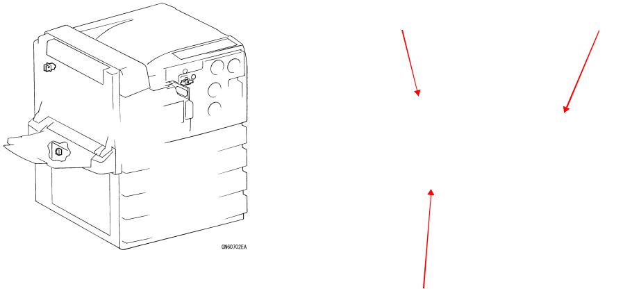
Power Supply
Before starting any service procedure, switch off the printer power and unplug the power cord from the wall outlet. If you must service the printer when the power is applied, be aware of the potential for electrical shock and do all tasks by following the procedures in this manual.
WARNING Do not touch any live part unless you are instructed to do so by a service procedure. The power supply switch/inlet part (MAIN POWER SWITCH & INLET) is live even when the power switch has been turned off. Do not touch any live part.
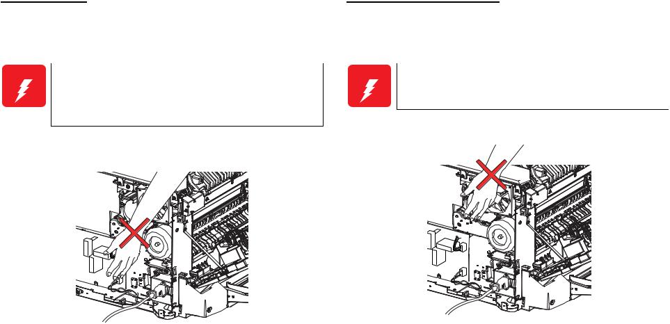
Mechanical Components
If you service a driving assembly (e.g., gears), first turn off the power and unplug the power cord. Then manually rotate the assembly.
WARNING Do not touch the driving part (e.g., gears) while the assembly (printer) is being driven.
GN006EA
GN005EA
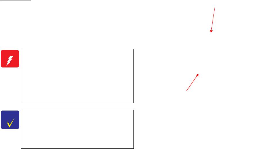
Safety Components
The printer is equipped with safety components (e.g., interlock switches, fuses, thermostat) and safety switches for protecting users and service personnel from injury and the equipment from damage. Never handle the printer in such a way that the normal functioning of the safety components is disturbed.
The major safety devices which this printer is equipped with are the following three interlock switches:
FRONT COVER OPEN SENSOR
When the Front Cover opens, the FRONT COVER OPEN SENSOR turns off to cut off +5VDC supplied to each color LDD PWB of the ROS.
INTERLOCK SWITCH
When the Left Cover of the printer main unit opens, the INTERLOCK SWITCH turns off to cut off +24VDC supplied to the DRIVE ASSY MAIN, HVPS, GATE SOLENOID and DUPLEX PWB.
LH COVER INTL SW
When the Left Cover of any additional tray opens, the LH COVER INTL SW turns off.
INTERLOCK SWITCH |
FRONT COVER OPEN SENSOR |
LH COVER INTL SW (Tray Module)
Laser Beam
The printer has an interlock switch (FRONT COVER OPEN SENSOR) to prevent exposure to a laser beam from the laser beam output unit (ROS ASSY). This switch turns off when the Front Cover opens. (For details of the switch, refer to the “Safety Components” in the previous section.)
During your maintenance work, never turn on this switch forcibly by other than ordinary operation since doing so may cause the laser beam to be emitted.
WARNING |
Exposure of your eyes to a laser beam may lead to |
|
blindness. |
|
Never open the Cover where the Warning Label About |
|
Laser Beam is affixed. |
|
If you disassemble or assemble the printer, turn off the |
|
power. |
|
If you need to work on the printer with power applied, |
|
strictly follow the instructions in this manual. |
|
Understand how the laser beam functions and take |
|
maximum precautions not to injure yourself or anyone |
|
around you. |
CHECK |
The laser beam has a narrower frequency band and more |
POINT |
coherent phases than any other light (sunlight, electric |
|
light). The beam has excellent monochromaticity and |
|
convergence, thus it reaches long distances. Because of |
|
these characteristics, the laser beam converges into one |
|
point, causing high density and high temperature. |
|
Therefore, a laser beam is harmful to the human body. |
|
The laser beam in this printer is invisible. |
Warning Label
(Refer to “Warning Label About Laser Beam”)
ROS ASSY

High Temperature Assembly
To prevent you from becoming injured or burned, do the following: Before working with a high temperature assembly (e.g., Fuser unit), be sure to turn off the power, unplug the power cord and wait until it cools down adequately.
CAUTION The high temperature assembly is very hot immediately after any printer operation. Wait at least 20 ~ 30 minutes,
until the printer cools down adequately.
Caution Label
(Refer to “Caution Label About High-temperature Surface”)
Fuser unit
GN004EA
Ozone
Because of the printing principle of laser printers, this machine emits a very small amount of ozone in the process of printing. (The exhaust air may smell of ozone.) This printer generates only a very small amount of ozone that never exceeds the safety permissible value (0.1 ppm / 0.2 mg/m3) in the normal work environment. Avoid operating the printer under any of the following conditions:
Any ambient conditions other than specified for use of this printer Use of two or more laser printers in a small room
Use in a place where sufficient ventilation is not available
Especially, continuous operation for an extended period of time under any of the above-mentioned conditions

Warning/Caution Labels
Warning labels and caution labels are affixed to this printer for accident prevention.
CHECK |
In maintenance work, check that the labels are free from |
POINT |
peeling and soiling. |
|
|
Warning Label About Laser Beam
Stuck on the top of the laser beam emitting unit (ROS ASSY) to warn the maintenance personnel of danger of exposure to the laser beam.
(Refer to “Laser Beam”)
Caution Label About High-temperature Surface
Stuck on the side wall of the Fuser unit, which becomes hot, in order to warn the user of danger of suffering a burn.
(Refer to “High Temperature Assembly”)
Warning Label About Toner
Stuck on the Waste toner collector and Toner Cartridge to prevent dust explosion caused by toner. This Warning Label prohibits you from throwing toner into fire.

Parts
To prevent you from becoming injured, keep the following in mind:
When handling a heavy part (device included), pay careful enough attention to your working posture to prevent back pain.
CAUTION Handle a heavy part with extreme care. Handling it in an inadvertent posture may put a load on your back or cause
you to drop the part.
Be careful not to injure yourself with the sharp edges of the parts.
Do not work with wet or oily hands-you may drop a part or injure yourself. Dry your hands first.
When pulling out a part (including a harness), do not use too much force. Pull out the part carefully and slowly step by step.
Consumables
Understand the following explanation and handle the consumables carefully.
Some parts may cause a particulate explosion or fire if handled improperly. Do not handle these parts near fire or throw into a fire.
Some materials, especially toner, may cause bodily injury. Do not swallow or inhale such materials or allow them to come in contact with the eyes. Help to protect those around you and follow the prohibitions against swallowing or inhaling such materials. Be careful to protect the eyes at all times.
Place a sheet inside or under the printer so that the floor or workbench is protected.
If the Developer or Fuser Oil gets on your clothing, dry it with a cloth and wash with clean water.
To prevent ignition, explosion, burn, injury, etc., do not use a general vacuum cleaner for cleaning dropped toner. (To do so may cause the toner to catch fire by sparks in the vacuum cleaner.)
WARNING Do not pick up dropped toner with a general vacuum cleaner. To do so may cause ignition.
GN009EB
Improper Printer Use
Modifying, revising, tampering with the printer, especially to the safety mechanism, is strictly prohibited in all circumstances.

PL5.1.20 |
|
PL5.1.9 LVPS |
|
|
|
ON/OFF CONTROL |
|
|
|
||||||
MAIN POWER |
|
|
|
|
|
|
|
|
|
|
|
||||
|
|
|
|
|
|
|
|
|
(SLEEP) |
|
|
|
|
||
SWITCH & INLET |
|
|
|
|
|
|
|
|
|
|
|
|
|
||
|
|
|
|
|
|
|
|
|
|
|
|
|
|
|
|
AC N |
AC N |
|
|
|
|
DC Power Supply |
|
|
|
|
|
|
|
|
|
|
|
|
|
|
|
|
|
|
|
|
|
|
|||
|
|
|
|
|
|
|
|
|
|
|
|
|
|
||
AC H |
|
Fuse |
|
|
+3.3VDC |
+3.3VDC |
+5VDC |
+24VDC |
|
|
|||||
AC H |
|
|
(CONT) |
|
(IOT) |
|
|
|
|
PL2.1.16 |
|||||
|
|
|
|
|
|
RET+3.3V |
RET+3.3V |
RET +5V |
RET +24V |
INTERLOCK |
|||||
|
|
|
|
|
|
|
|
|
|
|
|
|
|
SWITCH |
|
FG |
|
|
|
|
|
|
|
|
|
|
|
|
|
+24VDC |
|
PL4.1.6 |
|
Fuse |
|
|
SG |
|
|
|
|
|
|
|
+24VDC-I/L |
|
|
|
|
|
|
|
|
|
|
|
|
|
|
|
|
||
FUSER UNIT |
|
|
|
|
|
|
|
|
|
|
|
|
|
|
|
|
|
|
|
|
|
|
|
|
|
|
|
|
|
|
|
|
AC H |
|
|
|
|
|
|
|
|
|
|
|
|
|
|
Thermostat |
|
|
|
|
|
|
|
|
|
|
|
|
|
+24VDC-I/L |
PL5.1.24 |
|
|
AC N |
|
|
|
|
|
|
|
|
|
HVPS |
|||
|
|
|
|
|
|
|
|
|
|
|
|
|
|
||
|
MAIN HEATER ON |
|
|
|
|
|
|
|
|
|
|
+24VDC |
|
|
|
Main Heater |
ACH |
Heater |
|
|
|
|
|
|
|
|
+24VDC-I/L |
PL2.11.1 |
|||
|
|
|
|
|
|
|
|
|
|
|
|||||
|
|
|
|
|
|
|
|
|
|
+24VDC-I/L |
DRIVE ASSY |
||||
|
SUB HEATER ON |
Control |
|
|
|
|
|
|
Fan |
|
|||||
|
|
+3.3VDC-CONT |
|
|
|
|
+24VDC |
|
MAIN |
||||||
|
|
|
|
|
|
+3.3VDC |
+5VDC |
|
|
||||||
Sub Heater |
ACH |
|
|
|
|
|
|
ONFAN |
|
|
|||||
|
|
|
|
|
|
|
|
|
Drive |
|
|
|
|
||
Thermistor |
STS1 |
|
|
|
|
|
|
|
|
|
|
|
|
+24VDC |
PL6.4.1 |
|
|
|
|
|
|
|
|
|
|
|
|
|
DRIVE ASSY |
||
SG |
|
|
|
|
|
|
|
|
|
|
|
|
|
|
PR |
|
|
|
|
|
|
|
|
|
|
|
|
|
|
|
|
|
|
+3.3VDCONHEATERMAIN |
|
+3.3VDCONHEATERSUB |
|
|
|
|
LOWFAN |
HIGHFAN |
PL5.1.17 |
|
|
|
|
|
|
|
|
|
|
|
FAN FUSER |
|
|
|
|||||
PL6.1.2 |
|
|
|
|
|
PL5.2.9 ESS PWB |
|
|
|
PL5.1.27 |
|
|
|
||
|
|
|
|
|
|
|
|
|
|
FAN LV |
|
|
|
||
DRUM UNIT |
|
|
|
|
|
|
|
|
|
|
|
|
|
|
|
|
|
|
|
|
|
|
|
|
|
|
PL2.5.30 |
|
|
|
|
PWBA CRUM |
|
|
|
|
|
|
|
|
|
|
V-TRA FAN |
|
|
|
|
SG |
|
|
|
|
|
PL5.2.2 MCU PWB |
|
|
|
|
|
|
+24VDC |
PL6.3.28 |
|
|
CLKCRUM DATACRUM +3.3VDC |
|
|
|
|
|
|
|
|
|
|
||||
|
Heater |
|
|
|
|
|
|
+24VDC |
|
|
MOTOR DISP Y |
||||
|
|
|
|
|
|
|
|
|
|
||||||
|
|
|
|
|
|
|
|
|
|
|
|||||
|
|
Control |
|
+3.3VDC |
|
|
|
|
|
|
+24VDC |
PL6.3.29 |
|||
PL1.1.6 |
|
|
|
|
|
|
|
|
|
|
|
||||
|
|
|
|
|
|
|
|
|
Fan |
+24VDC |
|
|
MOTOR DISP M |
||
FRONT COVER |
|
|
CRU |
|
|
|
|
|
|
|
|
||||
|
|
|
|
|
|
|
Control |
|
|
|
|
|
|||
OPEN SENSOR |
|
detection |
|
|
|
|
|
|
|
+24VDC |
PL6.3.26 |
||||
|
|
|
|
|
|
|
|
|
|||||||
|
FRONTCOVER CLOSED |
|
|
+24VDC-I/L |
|
|
|
|
|
|
|
|
MOTOR DISP C |
||
|
|
|
|
|
|
|
|
|
|
|
|
||||
SG |
|
|
|
(L/H COVER CLOSED) |
|
|
|
|
|
|
+24VDC |
PL6.3.27 |
|||
|
|
|
|
|
|
|
|
|
|
|
|
|
|||
PL3.1.3 |
|
|
|
|
|
|
|
|
|
|
|
|
|
|
MOTOR DISP K |
|
|
|
|
|
|
|
|
|
|
|
|
|
|
|
|
ROS ASSY |
|
Interlock |
|
+3.3VDC |
|
|
|
|
|
|
|
+24VDC |
PL6.5.12 |
||
|
|
|
|
|
|
|
|
|
|
|
|||||
|
LD+5VDC |
|
+5VDC |
|
|
|
|
|
|
|
MOTOR ASSY |
||||
LD (Y/M/C/K) |
Control |
|
|
|
|
|
|
|
|
|
|||||
|
|
|
|
|
|
|
|
|
TRACKING |
||||||
|
|
|
|
|
|
|
|
|
|
|
|
|
|
|
|
SG |
|
|
|
|
|
|
|
|
|
|
|
|
|
|
|
ROS Motor |
+24VDC |
|
|
|
|
|
|
|
|
|
|
|
|
(Face Up Tray) |
|
|
|
|
|
|
|
|
|
|
|
|
|
|
|
PL20.1.3 |
|
SG |
|
Cover Open/Closed +3.3VDC |
|
|
|
|
|
|
+24VDC-I/L |
||||||
|
|
|
|
|
|
I/L |
GATE |
||||||||
|
|
|
Control |
|
|
|
|
|
|
|
|
SOLENOID |
|||
|
CLOSED |
MOTOREXIT CLKON MOTORDUPLEX |
CLKON |
|
|
|
|
+3.3VDC |
+5VDC |
|
|
+24VDC |
+24VDC- |
|
|
|
COVERDUP |
+5VDC |
|
|
|
+3.3VDC |
+24VDC |
|
|
PL21.7.5/22.5.4 |
|||||
|
|
|
|
|
|
|
|
|
|
|
+24VDC |
||||
|
|
|
|
|
+24VDC-I/L |
|
|
|
|
|
|
|
MOTOR ASSY |
||
|
|
|
|
|
|
|
|
|
|
|
|
|
|||
|
|
|
|
|
|
|
|
|
|
|
|
|
|
|
3TM |
PL20.3.9 |
|
|
|
|
|
+24VDC-I/L PL20.4.12 |
|
PL21.7.3 |
|
|
|
PL21.3.12 |
|||
|
|
|
|
|
EXIT MOTOR PL20.4.11 |
|
|
|
|
||||||
|
|
|
|
|
|
|
3TM/STM +3.3VDC |
|
|
FEED/LIFT MOTOR |
|||||
DUPLEX COVER |
|
|
|
|
|
|
DUPLEX CLUTCH |
/22.5.7 |
|
|
+24VDC |
/21.4.12/22.2.12 |
|||
OPEN SWITCH |
|
|
|
|
|
|
|
|
|
PWB ASSY |
|
|
|
TRAY2 4 |
|
|
|
Control |
|
|
ON CLK |
EXIT MOTOR |
|
Cover Open/Closed |
|
PL21.6.13/22.4.12 |
|
||||
|
|
Logic |
|
|
|
|
|
||||||||
|
|
|
|
DUPLEX MOTOR |
|
|
|
|
|
|
|||||
SG |
|
|
|
|
|
PL20.4.10 |
|
|
Control |
|
LH COVER |
|
|||
|
|
|
|
|
ON CLK |
|
|
|
|
|
INTL SW |
|
|||
|
PL20.3.27 DUPLEX PWB |
|
DUPLEX MOTOR |
|
|
LH COVER CLOSED |
|
|
|||||||
PL20.1.6 |
|
|
|
|
PL21/22 |
|
|
||||||||
|
|
|
|
|
|
|
|
|
|
|
|
SG |
|||
DUPLEX ASSY |
|
|
|
|
|
|
|
|
|
3 Tray Module/Single Tray Module |
|||||
Diagram Outline System Safety
GN007EA

Other Precautions
Paper Storage
When paper is not loaded in the printer, enclose it in a packing material or put it in a plastic or similar bag to prevent dehumidification/moisture absorption in order to optimize print images.
Opening and Closing of LH ASSY during Work
If you have opened and closed the LH ASSY with the printer off, always power on the printer after closing the LH ASSY to warm it up, and then finish your work.
If you do not warm up the printer, the BTR Drive Gear is left in improper engagement and the BTR Roll will be deformed, affecting the print quality.
LH ASSY
GN008EA

|
|
Revision Status |
|
|
|
Revision |
Date of Issue |
Description |
A |
August 26, 2004 |
First release |
|
|
|
|
|
|
|
|
|

EPSON AcuLaser C9100 |
Revision A |
CONTENTS
Chapter 1 PRODUCT DESCRIPTION
1.1 |
Overview. ................................................................................................. |
21 |
|
|
1.1.1 |
Engine features . .............................................................................. |
21 |
|
1.1.2 |
Controller features. .......................................................................... |
22 |
|
1.1.3 |
Software features . ........................................................................... |
22 |
1.2 |
Basic Specifications. ................................................................................ |
23 |
|
|
1.2.1 |
Process Specifications & System. ................................................... |
23 |
|
1.2.2 |
Printer Basic Specifications. ............................................................ |
23 |
1.3 |
Adjustment Mechanisms . ........................................................................ |
31 |
|
1.4 |
Paper Specifications. ............................................................................... |
32 |
|
|
1.4.1 Paper Type. ..................................................................................... |
32 |
|
|
1.4.2 |
Paper that may Cause Printing Defects, Paper Jams or Printer Mal- |
|
|
functions . ................................................................................................... |
32 |
|
|
1.4.3 Types of Paper Feed. ...................................................................... |
33 |
|
|
1.4.4 |
Printing Area. ................................................................................... |
34 |
1.5 |
Reliability and Serviceability . ................................................................... |
35 |
|
|
1.5.1 |
Reliability . ........................................................................................ |
35 |
|
1.5.2 |
Durability . ........................................................................................ |
36 |
|
1.5.3 |
Serviceability . .................................................................................. |
36 |
1.6 |
Operating Conditions |
|
|
(Including Consumables). ............................................................................... |
37 |
||
|
1.6.1 Space Requirements. ...................................................................... |
37 |
|
1.7 |
Storage and Transport of the Main Unit (Packaged) and Optional Products |
||
38 |
1.7.1 |
Temperature and Humidity Conditions |
38 |
|
|||
|
1.7.2 |
Storage Altitude. .............................................................................. |
38 |
|
1.7.3 |
Dropping. ......................................................................................... |
38 |
1.8 |
Electrical Characteristics . ........................................................................ |
39 |
|
|
1.8.1 |
Electrical Fast Transient /Bursts (AC Line Noise) ........................... |
39 |
|
1.8.2 |
Instantaneous Outages . .................................................................. |
39 |
1.8.3 |
Resistance to Static Electricity . ....................................................... |
39 |
1.8.4 |
Inrush Current . ................................................................................ |
39 |
1.8.5 |
Insulation Resistance . ..................................................................... |
39 |
1.8.6 |
Dielectric Strength. .......................................................................... |
39 |
1.8.7 |
Leak Current . .................................................................................. |
39 |
1.9 Compliance with Standards and Regulations. ......................................... |
40 |
|
1.9.1 |
Safety Standards. ............................................................................ |
40 |
1.9.2 |
Safety Standards (Laser Transmission). ......................................... |
40 |
1.9.3 EMI Standards . ............................................................................... |
40 |
|
1.9.4 |
Power Supply Harmonics and Flicker . ............................................ |
40 |
1.9.5 Power Consumption. ....................................................................... |
40 |
|
1.9.6 |
Other . .............................................................................................. |
40 |
1.10 Supplies/Periodic Replacement Units . .................................................. |
41 |
|
1.10.1 |
Specifications . ............................................................................... |
41 |
1.10.2 Packaged Storage and Transport Environment ............................ |
42 |
|
1.11 External Appearance and Unit Names . ................................................. |
43 |
|
1.11.1 Unit names . ................................................................................... |
43 |
|
1.12 Notes When Replacing Supplies and Installing Optional Products ....... |
45 |
|
1.12.1 Consumables . ............................................................................... |
45 |
|
1.13 Engine Restrictions/Limitations . ............................................................ |
46 |
|
1.13.1 |
Toner Duty Limit. ........................................................................... |
46 |
1.13.2 |
Issues that Limit Printing Speed. ................................................... |
46 |
1.14 Controller Specifications. ....................................................................... |
48 |
|
1.14.1 |
Controller basic specifications. ...................................................... |
48 |
1.14.2 |
Controller Configuration . .............................................................. |
49 |
1.14.3 |
External Interface Specifications. .................................................. |
50 |
1.15 Control Panel. ........................................................................................ |
52 |
|
1.15.1 External Appearance and Names . ................................................ |
52 |
|
1.15.2 |
Panel Settings List . ....................................................................... |
53 |
1.15.3 |
Description of Menus and Settings . .............................................. |
64 |
1.15.4 |
Special Operations. ....................................................................... |
69 |
15 

EPSON AcuLaser C9100 |
Revision A |
1.16 |
Printer Status........................................................................................ |
70 |
|
1.16.1 |
List of Printer Messages............................................................... |
70 |
|
1.16.2 |
Status Messages and Troubleshooting ........................................ |
72 |
|
1.16.3 |
Error Messages and Troubleshooting .......................................... |
73 |
|
1.16.4 |
Warning Messages and Troubleshooting..................................... |
75 |
|
1.16.5 |
Service Call Error Messages........................................................ |
76 |
|
1.17 |
Increasing the RAM .............................................................................. |
77 |
|
1.18 |
Handling Precautions ........................................................................... |
78 |
|
1.18.1 |
Precautions When Turning Off the Power.................................... |
78 |
|
1.18.2 |
Precautions for High Temperature Parts...................................... |
78 |
|
1.19 |
Status Sheet ......................................................................................... |
79 |
|
1.20 |
Engine Status Sheet............................................................................. |
81 |
|
1.21 |
Color Registration Adjustment Sheet ................................................... |
82 |
|
1.22 |
Configuration Sheet.............................................................................. |
83 |
|
1.23 |
Paper Handling Algorithm..................................................................... |
84 |
|
Chapter 2 OPERATING PRINCIPLES
2.1 |
Print Process .......................................................................................... |
87 |
|
|
2.1.1 |
Overview ........................................................................................ |
87 |
|
2.1.2 |
Print Process Diagram ................................................................... |
88 |
|
2.1.3 |
Technical Explanation .................................................................... |
89 |
2.2 |
Flow of Print Data ................................................................................... |
92 |
|
|
2.2.1 |
Data Flow ....................................................................................... |
92 |
2.3 |
Drive Transmission Path ........................................................................ |
93 |
|
|
2.3.1 DRIVE ASSY MAIN........................................................................ |
93 |
|
|
2.3.2 DRIVE ASSY PR............................................................................ |
96 |
|
|
2.3.3 DUPLEX ASSY .............................................................................. |
97 |
|
|
2.3.4 3 Tray Module ................................................................................ |
99 |
|
|
2.3.5 |
Single Tray Module ...................................................................... |
101 |
2.4 |
Feeding Paper ...................................................................................... |
103 |
|
|
2.4.1 Paper Feed Path Layout .............................................................. |
103 |
|
|
2.4.2 Paper Feed Path .......................................................................... |
103 |
|
2.5 |
Main Functions of Print Process........................................................... |
104 |
|
|
2.5.1 |
Main Structure and Functions ...................................................... |
104 |
|
2.5.2 Drum............................................................................................. |
106 |
|
|
2.5.3 ROS.............................................................................................. |
107 |
|
|
2.5.4 Development ................................................................................. |
108 |
|
|
2.5.5 |
Print and Detachment ................................................................... |
111 |
|
2.5.6 |
Collecting Toner ............................................................................ |
117 |
|
2.5.7 |
Process Control............................................................................. |
120 |
|
2.5.8 |
Fusing of Toner ............................................................................. |
122 |
|
2.5.9 Paper Feed ................................................................................... |
125 |
|
2.6 |
Paper Feed Mechanism ........................................................................ |
126 |
|
|
2.6.1 |
Paper Tray .................................................................................... |
127 |
|
2.6.2 Paper Feed ................................................................................... |
131 |
|
|
2.6.3 |
Ejection of Paper........................................................................... |
135 |
2.7 |
Electrical Circuitry and Control .............................................................. |
137 |
|
|
2.7.1 |
Low-voltage Power Supply............................................................ |
137 |
|
2.7.2 INTER LOCK................................................................................. |
139 |
|
|
2.7.3 |
Drives ............................................................................................ |
140 |
2.8 |
Various Detection Mechanisms............................................................. |
142 |
|
2.9 |
Electric Circuit Operation Principle........................................................ |
144 |
|
|
2.9.1 |
Main Features ............................................................................... |
144 |
|
2.9.2 |
Outline Specifications.................................................................... |
144 |
Chapter 3 TROUBLESHOOTING
3.1 |
Procedure for Troubleshooting.............................................................. |
148 |
|
|
3.1.1 |
Procedure for Troubleshooting...................................................... |
148 |
|
3.1.2 |
Preliminary Checks ....................................................................... |
148 |
|
3.1.3 |
Precautions in Performing Work ................................................... |
149 |
|
3.1.4 Precautions When Using FIP ........................................................ |
149 |
|
|
3.1.5 Warming-Up Flowchart At Power-ON .......................................... |
151 |
|
3.2 |
Level 1 FIP ............................................................................................ |
152 |
|
|
3.2.1 |
Level 1 FIP .................................................................................... |
152 |
|
3.2.2 |
Level 1 FIP Flowchart ................................................................... |
152 |
3.3 |
Level 2 FIP ............................................................................................ |
153 |
|
|
3.3.1 |
Level 2 FIP .................................................................................... |
153 |
|
3.3.2 |
List of Errors and Warnings........................................................... |
153 |
|
3.3.3 |
Service Call Errors ........................................................................ |
160 |
|
3.3.4 |
FIP................................................................................................. |
164 |
3.4 |
Printer Operation Trouble...................................................................... |
247 |
|
3.5 |
Image Quality Trouble ........................................................................... |
248 |
|
|
3.5.1 |
Image Quality Troubleshooting Entry Chart .................................. |
248 |
16

EPSON AcuLaser C9100 |
|
|
3.5.2 |
Image Quality FIP. ......................................................................... |
249 |
3.5.3 |
Periodic Image Trouble Occurrence Pitches................................. |
251 |
3.5.4 |
Test Print (IOT Test Pattern Print)................................................. |
252 |
3.5.5 |
FIP. ................................................................................................ |
254 |
3.6 Appendix. ............................................................................................... |
290 |
|
Chapter 4 DISASSEMBLY AND ASSEMBLY |
|
|
4.1 Overview. ............................................................................................... |
293 |
|
4.1.1 |
Precautions . .................................................................................. |
293 |
4.1.2 |
Used Screw List . ........................................................................... |
296 |
4.1.3 |
Tools. ............................................................................................. |
297 |
4.1.4 Disassembly and Reassembly Procedure..................................... |
297 |
|
4.2 Cover . .................................................................................................... |
298 |
|
4.2.1 COVER ASSY RIGHT, COVER ASSY FRONT ............................ |
298 |
|
4.2.2 COVER HIGH ASSY TOP, CONTROL PANEL ............................ |
299 |
|
4.2.3 COVER ASSY REAR, COVER RH LOW...................................... |
302 |
|
4.2.4 COVER FRONT LH LOW, COVER REAR LH LOW..................... |
303 |
|
4.2.5 FRONT COVER OPEN SENSOR. ................................................ |
304 |
|
4.3 Paper Transport. .................................................................................... |
305 |
|
4.3.1 BTR UNIT ASSY . .......................................................................... |
305 |
|
4.3.2 INTERLOCK SWITCH. .................................................................. |
306 |
|
4.3.3 LH ASSY . ...................................................................................... |
307 |
|
4.3.4 MSI, ROLL ASSY TURN ............................................................... |
310 |
|
4.3.5 ROLL ASSY FEED ENV, ROLL ASSY FEED, |
|
|
HOLDER ASSY RETARD, SPRING RETARD ....................................... |
312 |
|
4.3.6 PLATE ASSY BOTTOM, SPRING PICK UP, GEAR PICK UP, GEAR |
||
CAM . |
....................................................................................................... |
314 |
4.3.7 SOLENOID ASSY . ........................................................................ |
316 |
|
4.3.8 MSI TRAY . .................................................................................... |
317 |
|
4.3.9 MSI NO PAPER SENSOR ............................................................ |
319 |
|
4.3.10 GUIDE SIDE FRONT, GUIDE SIDE REAR ................................ |
320 |
|
4.3.11 CAP FUT, COVER EXIT . ............................................................ |
321 |
|
4.3.12 HANDLE ASSY L/H, WIRE ASSY GND...................................... |
322 |
|
4.3.13 CHUTE TRANS, V-TRA FAN. ..................................................... |
324 |
|
4.3.14 POP SENSOR. ............................................................................ |
325 |
|
4.3.15 ROLL PINCH TURN, SPRING TURN ......................................... |
326 |
|
4.3.16 KIT CHUTE TRANS . ................................................................... |
327 |
|
4.3.17 ROLLER ASSY EXIT 1 . .............................................................. |
328 |
|
|
Revision A |
|
|
4.3.18 GATE ASSY FUT. ....................................................................... |
329 |
|
4.3.19 CLUTCH ASSY SPRING . ........................................................... |
330 |
|
4.3.20 CHUTE FUT UP. ......................................................................... |
331 |
|
4.3.21 PH MAIN ASSY. .......................................................................... |
332 |
|
4.3.22 BEARING ONEWAY, CLUTCH ASSY FEED, ROLL ASSY TURN |
|
|
... 334 |
|
|
4.3.23 SENSOR ASSY MOB ADC. ........................................................ |
337 |
|
4.3.24 CLUTCH REGI, CHUTE PH . ...................................................... |
338 |
|
4.3.25 ACTUATOR REGI, SENSOR REGI, OHP SENSOR.................. |
340 |
|
4.3.26 LEVEL SENSOR 1, LEVEL SENSOR 2 ..................................... |
342 |
|
4.3.27 NO PAPER SENSOR, SENSOR ASSY PAPER ........................ |
343 |
|
4.3.28 SWITCH ASSY SIZE, SENSOR ASSY TRACKING ................... |
344 |
|
4.3.29 SHAFT ASSY, ROLL ASSY FEED, ROLL ASSY SIDE.............. |
345 |
|
4.3.30 HOLDER ASSY RETARD. .......................................................... |
347 |
|
4.3.31 CAM SIZE, PIN LOCKING, GEAR IDLE..................................... |
348 |
|
4.3.32 GUIDE ASSY END. ..................................................................... |
349 |
|
4.3.33 GUIDE ASSY SIDE R, GUIDE ASSY SIDE F............................. |
350 |
|
4.3.34 ACTUATOR N/E . ........................................................................ |
352 |
|
4.3.35 DRIVE ASSY MAIN. .................................................................... |
353 |
|
4.3.36 CLUTCH ASSY FEED . ............................................................... |
355 |
4.4 ROS........................................................................................................ |
357 |
|
|
4.4.1 ROS ASSY. ................................................................................... |
357 |
|
4.4.2 KIT HEATER ASSY, KIT HEATER DELE ASSY .......................... |
358 |
4.5 |
Fuser and Exit Transport. ...................................................................... |
361 |
|
4.5.1 Fuser unit . ..................................................................................... |
361 |
|
4.5.2 TRANSPORT EXIT ASSY, SENSOR ASSY TP ........................... |
362 |
|
4.5.3 ROLL ASSY EXIT 2 . ..................................................................... |
364 |
|
4.5.4 FUSER DRAWER CONNECTOR. ................................................ |
366 |
4.6 |
Electrical................................................................................................. |
368 |
|
4.6.1 SENSOR HUM TE . ....................................................................... |
368 |
|
4.6.2 FAN FUSER. ................................................................................. |
369 |
|
4.6.3 FAN LV. ......................................................................................... |
370 |
|
4.6.4 HVPS . ........................................................................................... |
371 |
|
4.6.5 LVPS & MAIN POWER SWITCH. ................................................. |
373 |
|
4.6.6 BOARD ASSY, MAIN. ................................................................... |
375 |
|
4.6.7 ESS BOX . ..................................................................................... |
378 |
|
4.6.8 MCU PWB, X-ROM PWB. ............................................................. |
382 |
4.7 Deve. And Xero. . ................................................................................... |
384 |
|
17 

EPSON AcuLaser C9100 |
Revision A |
4.7.1 TONER FULL SENSOR, |
|
TONER BOTTLE SET SENSOR............................................................ |
384 |
4.7.2 IDT UNIT, Photoconductor unit .................................................... |
386 |
4.7.3 TONER DISPENSER ASSY ........................................................ |
389 |
4.7.4 DEVE UNIT K (C, M, Y) ............................................................... |
392 |
4.7.5 AUGER (Y/M/C/K)........................................................................ |
397 |
4.7.6 MOTOR DISP (Y/M/C/K).............................................................. |
399 |
4.7.7 ANTENNA CK, ANTENNA YM..................................................... |
401 |
4.7.8 HSG-CTRG (Y/M/C/K) ................................................................. |
403 |
4.7.9 DRIVE ASSY PR.......................................................................... |
405 |
4.7.10 GEAR ASSY HR ........................................................................ |
406 |
4.7.11 TRACKING ASSY FRONT......................................................... |
407 |
4.7.12 MOTOR ASSY TRACKING........................................................ |
408 |
4.7.13 SHAFT ASSY TRACKING ......................................................... |
409 |
4.7.14 GEAR HIGH ASSY DEVE.......................................................... |
411 |
4.7.15 COVER ASSY INNER................................................................ |
413 |
4.8 Duplex and Side Tray ........................................................................... |
414 |
4.8.1 DUPLEX ASSY ............................................................................ |
414 |
4.8.2 TRAY ASSY EXIT, CHUTE ASSY FUT ....................................... |
416 |
4.8.3 GATE SOLENOID ........................................................................ |
417 |
4.8.4 GUIDE DUP IN, DUPLEX FRAME COVER ................................. |
418 |
4.8.5 DUPLEX PWB.............................................................................. |
419 |
4.8.6 DUPLEX DRIVE ........................................................................... |
420 |
4.8.7 DUPLEX ROLL............................................................................. |
421 |
4.8.8 GATE DUPLEX ............................................................................ |
423 |
4.8.9 DUPLEX SENSOR, |
|
DUPLEX COVER OPEN SWITCH......................................................... |
424 |
4.8.10 ROLL DCL RUBBER.................................................................. |
426 |
4.8.11 CAM DCL, LEVER DCL ............................................................. |
427 |
4.8.12 EXIT MOTOR, DUPLEX MOTOR, DUPLEX CLUTCH .............. |
428 |
4.8.13 DUPLEX FRAME ASSY............................................................. |
430 |
4.9 3 Tray Module / Single Tray Module..................................................... |
431 |
4.9.1 3 Tray Module .............................................................................. |
431 |
4.9.2 FRONT UPPER COVER, RIGHT COVER, LEFT LOWER COVER, |
|
REAR COVER........................................................................................ |
432 |
4.9.3 TRAY 2 FEEDER ......................................................................... |
433 |
4.9.4 TRAY 3 FEEDER ......................................................................... |
434 |
4.9.5 TRAY 4 FEEDER ......................................................................... |
435 |
4.9.6 PAPER SIZE SENSOR ................................................................ |
436 |
4.9.7 KIT FEED/RETARD/NUDGER ROLL .......................................... |
437 |
4.9.8 ONEWAY CLUTCH, ONEWAY GEAR, FRICTION CLUTCH....... |
438 |
4.9.9 ACTUATOR SNR, TRAY NO PAPER SENSOR........................... |
439 |
4.9.10 TRAY LEVEL SENSOR .............................................................. |
440 |
4.9.11 TRAY FEED OUT SENSOR ....................................................... |
441 |
4.9.12 ACTUATOR ................................................................................ |
442 |
4.9.13 TRAY FEED/LIFT MOTOR ......................................................... |
443 |
4.9.14 TAKEAWAY ROLL ASSY ........................................................... |
444 |
4.9.15 TAKEAWAY SENSOR, LH COVER INTL SW ............................ |
445 |
4.9.16 LEFT COVER ASSY 3TM........................................................... |
447 |
4.9.17 MOTOR ASSY 3TM, PWB ASSY 3TM ....................................... |
448 |
4.9.18 STOPPER TRAY FR................................................................... |
449 |
4.10 Single Tray Module ............................................................................. |
450 |
4.10.1 Single Tray Module ..................................................................... |
450 |
4.10.2 LEFT COVER ASSY STM .......................................................... |
451 |
4.10.3 MOTOR ASSY STM, PWB ASSY STM ...................................... |
452 |
4.10.4 TRAY 4 FEEDER ........................................................................ |
453 |
4.11 Tray Assy ............................................................................................ |
454 |
4.11.1 LINK END.................................................................................... |
454 |
4.11.2 FRONT SIDE GUIDE, REAR SIDE GUIDE ................................ |
455 |
4.11.3 END GUIDE ASSY...................................................................... |
456 |
4.11.4 SIDE GUIDE ACTUATOR........................................................... |
457 |
Chapter 5 ADJUSTMENT
5.1 Overview ............................................................................................... |
459 |
|
5.1.1 |
Instructions.................................................................................... |
459 |
5.1.2 |
Part/unit-based adjustment items.................................................. |
460 |
5.2 Adjustment ............................................................................................ |
462 |
|
5.2.1 |
Color Registration Adjustment ...................................................... |
462 |
5.2.2 |
Color Registration Check .............................................................. |
466 |
5.2.3 |
Writing USB ID .............................................................................. |
467 |
5.2.4 |
Writing adjustment value............................................................... |
469 |
5.2.5 |
Controller Firmware Update .......................................................... |
472 |
5.2.6 MCU Firmware Update ................................................................. |
475 |
|
Chapter 6 MAINTENANCE
6.1 |
Overview ............................................................................................... |
478 |
6.2 |
About On-site Servicing......................................................................... |
480 |
18

EPSON AcuLaser C9100 |
Revision A |
|
6.2.1 |
On-site Servicing Flowchart . ......................................................... |
480 |
|
6.2.2 |
Details of On-site Servicing . .......................................................... |
481 |
6.3 |
Maintenance Menu . ............................................................................... |
483 |
|
|
6.3.1 Maintenance Menu Items . ............................................................. |
483 |
|
|
6.3.2 |
Entry into Maintenance Menu. ....................................................... |
486 |
6.4 |
Sheet for servicing. ................................................................................ |
487 |
|
|
6.4.1 |
Engine Status Sheet Items. ........................................................... |
487 |
|
6.4.2 |
Print Log Report . ........................................................................... |
492 |
6.5 |
Consumables and Periodical Replacement Parts ................................. |
494 |
|
|
6.5.1 Consumables . ............................................................................... |
494 |
|
|
6.5.2 |
Regular Replacement Parts . ......................................................... |
495 |
Chapter 7 APPENDIX
7.1 |
Connectors . ........................................................................................... |
497 |
|
|
7.1.1 |
P/J Layout Diagram. ...................................................................... |
497 |
7.2 |
Wiring Diagrams and Signal Information ............................................... |
513 |
|
|
7.2.1 |
How to use Overall Connection Wiring Diagrams ......................... |
513 |
|
7.2.2 |
How to use Detailed Connection Wiring Diagrams ....................... |
514 |
|
7.2.3 |
Overall Connection Wiring Diagrams ............................................ |
516 |
|
7.2.4 |
Detailed Connection Wiring Diagrams .......................................... |
519 |
7.3 |
Exploded Diagrams . .............................................................................. |
562 |
|
7.4 |
Parts List. ............................................................................................... |
604 |
|
7.5 |
Circuit Diagrams . ................................................................................... |
610 |
|
19 

C H1A P T E R
PRODUCT DESCRIPTION

 EPSON AcuLaser C9100
1.1 Overview
This printer is a non-impact color page printer that takes advantage of laser and electrophotographic technologies. It has resolution of 600/300 dpi, and print speed of 24.0ppm (A4 color)/24.0ppm (A4 monochrome).
In addition, CPGI is included as a full-color technology.
1.1.1 Engine features
High speed engine with a print speed of 24.0ppm (color) /24.0ppm (monochrome) and support for HLT to A3, and banner (up to 1,200mm).
Warming up time: |
30 seconds or less |
First print output time |
|
Color/A4 |
: 12.0 seconds |
Monochrome/A4 |
: 10.5 seconds |
Support for automatic duplex (option) |
|
Printing speed |
: 20.0ppm (A4, Color/Monochrome) |
Support for thick paper and transparencies
Ultra power saving is possible in sleep mode with the mechanical controller off.
Support for the following paper feed
A maximum of 2,150-sheet, 5-bin feed is possible.
Standard |
: Standard cassette (500 sheets) |
|
MP tray (150 sheets) |
|
(Accepts 1,200mm long paper) |
Option |
: Either of the following units can be loaded |
|
• 1,500-sheet paper cassette unit |
|
(500 sheets x 3 levels) |
|
• 500-sheet paper cassette unit |
|
(500 sheets x 1 level) |
Support for the following paper exit
Standard feed |
: Face-Down 500 sheets |
Option |
: Face-Up 150 sheets |
Revision A 
CSIC installed on Toner Cartridge and Photoconductor unit The replacement cartridge provides a large capacity cartridge.
Table 1-1. Number of sheets available for each Toner Cartridge (A4/5%)
Color |
Factory-installed cartridge |
Replacement cartridge |
BK |
7,500 sheets |
15,000 sheets |
Y |
6,000 sheets |
12,000 sheets |
M |
6,000 sheets |
12,000 sheets |
C |
6,000 sheets |
12,000 sheets |
PRODUCT DESCRIPTION |
Overview |
21 |
EPSON AcuLaser C9100 |
Revision A |
1.1.2 Controller features
Newly developed high speed controller
New RISC CPU : PowerPC750FX (600MHz)
DDR333 high speed memory
: DDR SODIMM (333MHz, CL=2.5)
Standard RAM 128MB, expandable to a maximum of 1,024MB with additional RAM
Color technology
Enhanced ASIC (FMV, FAIO)
New color registration adjustment function 3 types of standard interface
IEEE1284 compliant ECP supporting parallel I/F USB (2.0 HS) interface (D4 support) 10Base-T/100Base-TX
Adding RAM DIMM can improve the following functions Drawing area (CPGI, PGI)
Printing speed Resolution
Receive buffer capacity
Collation (when expanded to more than 128MB)
ROM update function when flash DIMM is installed (RCC supported) HDD can be installed (support for large-capacity types (40GB))
1.1.3 Software features
ESC/Page-Color
ESC/Page Color monochrome printing supported
(high speed automatic recognition of color/monochrome etc.)
Printer status and printer environment monitoring with bi-directional EJL and MIB
Support for PostScript 3 with the optional Adobe PostScript 3 module Support for PCL5C with the optional HP-PCL5 module
Version upgrade function for the engine controller ROM (Flash) Support for DCC commands (DIAG command only) Calibration function (with a change to the calibration table) Support for main unit serial numbers
PRODUCT DESCRIPTION |
Overview |
22 |

EPSON AcuLaser C9100 |
Revision A |
1.2 Basic Specifications
1.2.1 Process Specifications & System
System |
: Semiconductor laser beam scanning and 2- |
|
component dry electrophotographic system |
Exposure light source |
: 4-beam semiconductor laser |
Photoconductor |
: OPC (organic photoconductor) drum |
Charging |
: Roller charger |
Development |
: 2-component, contact development |
Toner |
: Non-magnetic toner |
Transfer |
: Intermediate transfer roller |
Intermediate transfer media : Roller |
|
Fixing |
: Belt heat fixing (free belt nip) |
1.2.2 Printer Basic Specifications
RESOLUTION
Main scanning 600 dpi x sub-scanning 600 dpi
WARMING UP TIME |
|
120V/200V |
: 30 seconds or less (at 22°C, 55% RH, rated voltage) |
|
The time until printing is possible after the power is |
|
turned on or when recovering from the sleep status |
|
after receiving a command from the controller. |
|
However, in a low temperature high humidity |
|
environment, warm up time may be + 270 s |
|
(condensation prevention mode). |
PRINTING SPEED MODE |
|
Full speed mode |
: Prints at the fastest speed of the main unit when |
|
printing plain paper, recycled paper, and fine paper. |
Low speed mode |
: Feeds paper at reduced speed to prevent loss of |
|
print quality when using special paper (thick paper, |
|
labels, envelopes, postcards). |
PRODUCT DESCRIPTION |
Basic Specifications |
23 |

EPSON AcuLaser C9100 |
Revision A |
PRINTING MODE BY PAPER TYPE
The main unit has 24 modes for the various media. Modes are switched by instructions from the controller. The engine determines the combination of modes corresponding to simplex/duplex printing and the media, and sets the process speed to one of 2 levels, full speed and low speed, as shown in the following table.
Table 1-2. Printing mode by paper type
Media compatible mode |
Paper type |
Printing speed mode |
|
Simplex |
Auto |
||
|
|
printing |
duplex |
Plain paper 1 mode |
60 to 80 gsm Japanese |
Full speed |
Full speed |
|
paper |
|
|
Plain paper 2 mode |
60 to 80 gsm overseas |
Full speed |
Full speed |
|
paper |
|
|
Recycled paper mode |
60 to 80 gsm recycled |
Full speed |
Full speed |
|
paper |
|
|
|
|
|
|
Fine paper mode |
81 to 105 gsm paper |
Full speed |
Full speed |
Thick paper 1 mode |
106 to 169 gsm thick |
Low speed |
--- |
|
paper |
|
|
|
|
|
|
Thick paper 2 mode |
170 to 216 gsm thick |
Low speed |
--- |
|
paper |
|
|
Transparency mode |
Transparency |
Low speed |
--- |
|
|
|
|
Label 1 mode |
Japanese labels |
Low speed |
--- |
Label 2 mode |
Overseas labels |
Low speed |
--- |
Envelope mode |
Envelopes |
Low speed |
--- |
Coated paper 1 mode |
106 to 169 gsm coated |
Low speed |
--- |
|
paper |
|
|
Coated paper 2 mode |
170 to 216 gsm coated |
Low speed |
--- |
|
paper |
|
|
Postcard mode |
Postcards |
Low speed |
--- |
Special mode (front side) |
Paper not supported by |
Full speed or |
Full speed* |
|
modes shown above |
low speed |
|
Plain paper 1 (reverse |
Plain paper 1 reverse side |
Full speed |
--- |
side) mode |
after printing |
|
|
|
|
|
|
Plain paper 2 (reverse |
Plain paper 2 reverse side |
Full speed |
--- |
side) mode |
after printing |
|
|
Table 1-2. Printing mode by paper type
Media compatible mode |
Paper type |
Printing speed mode |
||
Simplex |
Auto |
|||
|
|
printing |
duplex |
|
Recycled paper (reverse |
Recycled paper reverse |
Full speed |
--- |
|
side) mode |
side after printing |
|
|
|
|
|
|
|
|
Fine paper (reverse side) |
High quality paper reverse |
Full speed |
--- |
|
mode |
side after printing |
|
|
|
Thick paper 1 (reverse |
Thick paper 1 reverse |
Low speed |
--- |
|
side) mode |
side after printing |
|
|
|
Thick paper 2 (reverse |
Thick paper 2 reverse |
Low speed |
--- |
|
side) mode |
side after printing |
|
|
|
Coated paper 1 (reverse |
Coated paper 1 reverse |
Low speed |
--- |
|
side) mode |
side after printing |
|
|
|
|
|
|
|
|
Coated paper 2 (reverse |
Coated paper 2 reverse |
Low speed |
--- |
|
side) mode |
side after printing |
|
|
|
Postcard (reverse side) |
Postcard reverse side |
Low speed |
--- |
|
mode |
after printing |
|
|
|
|
|
|
|
|
Special mode (reverse |
Reverse side of paper not |
Full speed or |
Full speed* |
|
side) |
supported by modes |
low speed |
|
|
|
shown above |
|
|
|
Note "*": 60 to 105 gsm paper only supported
PRINT MODE
Color mode : Color mode using Y, M, C, K toner Monochrome mode : Monochrome mode using only K toner
PRODUCT DESCRIPTION |
Basic Specifications |
24 |

 EPSON AcuLaser C9100
FIRST PRINT OUTPUT TIME
The time between receiving the Start command and output of the bottom edge of the first sheet from the paper output roller.
However, this excludes operations that fall under the restrictions on printing speed explained in “1.13 Engine Restrictions/Limitations” (p.46).
Table 1-3. List of first print output time (Unit: seconds or less)
Paper size |
Monochrome mode |
Color mode |
||
Simplex |
Duplex |
Simplex |
Duplex |
|
|
printing |
printing |
printing |
printing |
A4 |
10.5 |
19.0 |
12.0 |
20.5 |
A3 |
12.6 |
22.1 |
14.1 |
23.6 |
Note "*1": Paper used is A4 plain paper, printing speed mode is full speed mode. Paper feed is the standard universal cassette.
Paper output destination is face-down (standard). Speed varies if the paper feed or output is changed*2.
"*2": When using a feeder other than the standard universal cassette, the time shown below is added to the color mode time.
Table 1-4.
|
Paper feed |
Added time |
|
|
1-feeder cassette |
|
|
|
3-feeders cassette |
≤ |
640ms |
|
(1st feeder) |
|
|
500-sheet |
3-feeders cassette |
≤ |
800ms |
|
(2nd feeder) |
||
|
|
|
|
|
3-feeders cassette |
≤ |
1,090ms |
|
(3rd feeder) |
||
|
|
|
|
Revision A 
CONTINUOUS PRINTING SPEED
This excludes operations that fall under the restrictions on printing speed explained in “1.13 Engine Restrictions/Limitations” (p.46).
Table 1-5. List of continuous printing speed (Unit: PPM) *1
Paper size
Standard size 1*2
•A4, Letter Standard size 2*2
•Executive, B5, A5, HLT, GLT Standard size 4*2
•GLG, Legal, B4, F4 Standard size 5*2
•A3, Ledger
C6, DL, COM-10, Monarch ISO-B5
Transparency*4 User defined size
•L*3=216 or less User defined size
•216 < L*3 ≤ 297 User defined size
•297 < L*3 ≤ 364 User defined size
•364 < L*3 ≤ 432
Simplex printing |
Duplex printing |
|
Full speed |
Low speed |
Full speed |
mode |
mode |
mode only |
24.0 |
12.0 |
20.0 |
24.0 |
12.0 |
11.0 |
15.0 |
7.5 |
8.5 |
13.0 |
6.5 |
7.8 |
--- |
12.0 |
--- |
--- |
9.0 |
--- |
--- |
6.0 |
--- |
24.0 |
12.0 |
11.0 |
18.0 |
9.0 |
9.5 |
15.0 |
7.5 |
8.5 |
13.0 |
6.5 |
7.8 |
Note "*1": The same speed for any paper feed
"*2": For details on the paper orientation, refer to “Supported paper size, type and orientation (p.27)”.
Indicates a length of up to 216mm. "*3": Paper length size (mm)
"*4": For transparencies, the printer switches to the standard size A4 low speed mode. However since the sheets are printed with an interval of 1 sheet to prevent sticking, the actual speed is 6.0ppm.
PAPER FEED REFERENCE
Center-line reference for each paper size, 500-sheet paper cassette unit (option), and 1500-sheet paper cassette unit (option).
PRODUCT DESCRIPTION |
Basic Specifications |
25 |

EPSON AcuLaser C9100 |
Revision A |
PAPER FEED
Table 1-6. Paper feed
|
|
|
Capacity |
Height |
|
|
Usable |
|
|
|
|
|
|
capacity |
|
|
|
|
Paper feed |
P |
J |
Paper type/Paper size |
paper basis |
|||
|
(number of |
|||||||
|
|
|
paper paper |
|
|
weight*1 |
||
|
|
|
|
|
sheets) |
|
|
|
|
|
|
|
|
|
A3, B4, A4, B5, A5, Ledger, |
|
|
|
|
Standard |
|
|
|
GLG, LEGAL, LETTER, |
|
|
|
|
560 |
500 |
|
EXECUTIVE |
60 to 216g/m2 |
||
|
|
universal |
54mm (max) |
|||||
|
|
sheets |
sheets |
User defined size: |
||||
|
|
cassette |
|
|
||||
|
|
|
|
|
Width |
: 182 to 297mm |
|
|
|
|
|
|
|
|
|
||
|
|
|
|
|
|
Length |
: 98.4 to 431.8mm |
|
|
|
|
|
|
|
|
|
|
|
|
|
|
|
|
A4, B5, A5, LETTER, HLT, GLT, |
|
|
Standard |
|
|
180 |
150 |
Paper smaller |
EXECUTIVE, C6, DL, COM-10, |
|
|
|
|
18mm (max) |
Width |
: 90 to 297mm |
|
|||
|
|
|
than LTR/A4 |
MONARCH, |
|
|||
|
|
|
sheets |
sheets |
size |
User defined size: |
|
|
|
|
MP tray |
|
|
|
Length |
: 98 to 216mm |
60 to 216g/m2 |
|
|
|
|
Paper larger |
A3, A4, Ledger, GLG, F4, |
|||
|
|
|
|
|
LEGAL,12"x18" |
|
||
|
|
|
100 |
100 |
than LTR/A4 |
User defined size: |
|
|
|
|
|
sheets |
sheets |
size |
Width |
: 298 to 304.8mm |
|
|
|
|
|
|
10mm (max) |
|
||
|
|
|
|
|
|
Length |
: 217 to 457.2mm*2 |
|
|
|
|
--- |
--- |
100 sheets |
Transparency (A4, LT) |
|
|
|
|
500-sheet |
|
|
|
A3, A4, B4, B5, LEDGER, GLG, |
|
|
|
|
|
|
|
LEGAL, LETTER |
|
||
|
|
cassette or |
560 |
500 |
|
|
||
|
|
54mm (max) |
User defined size: |
63 to 175g/m2 |
||||
Option |
|
1500-sheet |
sheets |
sheets |
||||
|
|
Width |
: 182 to 297mm |
|
||||
|
cassette |
|
|
|
|
|||
|
|
|
|
|
|
|||
|
|
|
|
|
Length |
: 182 to 431.8mm |
|
|
|
|
|
|
|
|
|
||
|
|
|
|
|
|
|
|
|
|
|
|
|
|
|
A3, A4, A5, B4, B5, Letter, |
|
|
|
|
Duplex unit |
--- |
--- |
--- |
Executive, Ledger, GLG, Legal, |
60 to 105g/m2 |
|
|
|
|
|
|
|
GLT, F4, HLT |
|
|
Note "*1": Refer to “1.4 Paper Specifications” (p32).
"*2": Lengths of up to 1,200 can be supported, however paper longer than 457.2 mm must be fed by hand one sheet at a time and must be supported by the operator.
OPTIONAL PAPER FEED COMBINATION
Besides the standard universal cassette and MP tray, the optional 500-sheet paper cassette unit or 1500-sheet paper cassette unit can be installed. This combination is shown in total number of sheets.
Table 1-7. List of optional paper feed combination (When using J paper)
|
Combination |
|
1 |
2 |
3 |
|
|
||||
Standard |
Standard universal cassette |
500 sheets |
|
|
|
MP tray (A4) |
150 sheets |
|
|
|
|
|
|
|
|
||
Option |
500-sheet paper cassette unit |
500 sheets |
--- |
|
--- |
|
|
|
|
|
|
1500-sheet paper cassette unit |
1500 sheets |
--- |
--- |
|
|
|
|
||||
|
Total number of sheets |
|
650 |
1,150 |
2,150 |
|
|
|
sheets |
sheets |
sheets |
|
|
|
|
|
|
CHECK Supplement about the optional cassette unit
POINT The 500-sheet paper cassette unit does not have casters. The 1500-sheet paper cassette unit has casters.
Both additional cassette units above cannot be installed at the same time.
PRODUCT DESCRIPTION |
Basic Specifications |
26 |

EPSON AcuLaser C9100 |
Revision A |
SUPPORTED PAPER SIZE, TYPE AND ORIENTATION |
|
Standard paper and plain paper
Special paper
Paper
A3
B4
A4
B5
A5
LEGAL
GLG
LETTER
LEDGER (B)
HLT
EXECUTIVE
GLT
F4
Transparency
Labels |
|
|
2 |
MONARCH |
|
*1 * |
Com-#10 |
|
Envelopes |
||
DL |
||
|
||
|
ISO-B5 |
|
|
C6 |
Table 1-8. List of supported paper size, type and orientation
Paper size |
|
Unit: mm (inches) |
MP tray |
Vertical (length) Horizontal (width) |
|
420.00297.00
364.00257.00
210.00297.00
182.00257.00
148.00210.00
355.60215.90
(14.00") |
(8.50") |
330.20215.90
(13.00") |
(8.50") |
215.90 |
279.40 |
(8.50") |
(11.00") |
431.80 |
279.40 |
(17.00") |
(11.00") |
139.70215.90
(5.50") |
(8.50") |
184.15 |
266.70 |
(7.25") |
(10.50") |
203.20 |
266.70 |
(8.00") |
(10.50") |
330.00210.00
A4: 210.00 |
A4: 297.00 |
||
LT: 215.90 |
LT: 279.40 |
||
A4: |
210.00 |
A4: |
297.00 |
LT: |
215.90 |
LT: |
279.40 |
98.43190.5
(3 7/8) |
(7 1/2) |
104.78241.30
(4 1/8) |
(9 1/2) |
110.00220.00
250.00176.00
114.00162.00 
Standard |
Optional paper |
|
Paper |
Face-up |
|
universal |
Duplex printing |
||||
cassette unit |
orientation |
output |
|||
cassette unit |
|
||||
|
|
|
|
||
|
|
|
SEF |
|
|
|
|
|
SEF |
|
|
|
|
|
LEF |
|
|
|
|
|
LEF |
|
|
|
--- |
|
LEF |
|
|
|
|
|
SEF |
|
|
|
|
|
SEF |
|
|
|
|
|
LEF |
|
|
|
|
|
SEF |
|
|
--- |
--- |
|
LEF |
|
|
--- |
--- |
|
LEF |
|
|
--- |
--- |
|
LEF |
|
|
--- |
--- |
|
SEF |
|
|
--- |
--- |
--- |
LEF |
|
|
--- |
--- |
--- |
LEF |
|
|
--- |
--- |
--- |
LEF |
--- |
|
--- |
--- |
--- |
LEF |
--- |
|
--- |
--- |
--- |
LEF |
--- |
|
--- |
--- |
--- |
SEF |
--- |
|
--- |
--- |
--- |
LEF |
--- |
Note "*1": The supported paper sizes differ depending on the destination.
"*2": For the orientation of envelopes, refer to “Envelope orientation (p.28)”.
Note : SEF (Short Edge Feed): The short edge of the paper is fed into the printer.
LEF (Long Edge Feed) : The long edge of the paper is fed into the printer. “---” = Not supported
PRODUCT DESCRIPTION |
Basic Specifications |
27 |

EPSON AcuLaser C9100
Envelope orientation |
|
|
|
|
|
|
|
|
Feed |
|
|
|
direction |
|
|
|
↓ |
|
|
|
|
|
|
|
Envelope |
ISO-B5 |
MONARCH, Com- |
|
type |
#10, DL, C6 |
|
|
|
||
Note 1: Place in the MP tray print side down with the flap open.
2: Only envelopes without adhesive or tape can be used.
PAPER OUTPUT
This product has a face-down output tray as standard, and a face-up unit as an option. The specifications are defined below.
Face-down (standard) |
|
Output location |
: Top of the printer |
Output tray capacity : 500 sheets (standard paper)
Paper size |
: All paper sizes that can be handled by the |
|
printer |
Paper type |
: All paper types that can be handled by the |
|
printer (60 to 216gsm) |
Face-up (when the optional face-up unit is installed)
Output location |
: Left side of the printer |
Output tray capacity : 150 sheets (standard paper)
Paper size |
: All paper sizes that can be handled by the |
|
printer, excluding paper sizes with vertical |
|
length of less than 135mm |
Paper type |
: All paper types that can be handled by the |
|
printer (60 to 216gsm) |
NOTE: Face-down and face-up can both accept paper longer than 457.2mm, however the results are not guaranteed.
Revision A
DIMENSIONS AND WEIGHT
Stand-alone dimensions and weight
Table 1-9. List of dimensions and weight (Unit: mm, kg)
|
Width |
Depth |
Height |
Weight |
|
||||
Main unit |
678.0 |
631.0 |
473.0 |
55.0 *1 |
500-sheet paper cassette unit |
565.0 |
591.0 |
121.0 |
12.0 |
1500-sheet paper cassette unit |
565.0 |
591.0 |
363.0 |
31.0 |
Note "*1": Not including the Toner Cartridge, Photoconductor unit, and Waste toner collector packaged with the main unit.
Note : Does not include projecting items.
Tolerance: Dimensions = ±1% mm, Weight = ±1% kg (however, 10kg or less is uniformly ±0.1kg)
|
678mm |
631mm |
473mm |
Figure 1-1. Outline Dimensions
PRODUCT DESCRIPTION |
Basic Specifications |
28 |

 EPSON AcuLaser C9100
Dimensions and weights with options installed
Table 1-10. List of dimensions and weights with options installed (Unit: mm, kg)
|
Width |
Depth |
Height |
Weight |
|
Main unit + duplex unit |
678.0 |
631.0 |
473.0 |
57.2 *1 |
|
Main unit + 1500 sheet paper cassette unit |
972.0 |
631.0 |
829.5 *2 |
90.55 *1 |
|
+ duplex unit + face-up tray |
|||||
|
|
|
|
Note "*1": Not including the Toner Cartridge, Photoconductor unit, and Waste toner collector packaged with the main unit.
"*2": Includes the height of the casters of the 500-sheet x 3-feeders cassette.
Note : Does not include projecting items.
Tolerance: Dimensions = ±1% mm, Weight = ±1% kg (however, 10kg or less is uniformly ±0.1kg)
SUPPLIES AND PERIODIC REPLACEMENT UNITS
Table 1-11. List of supplies and periodic replacement units
Classification |
Replacement unit |
|
|
Toner Cartridge |
|
Supplies |
(Black, Cyan, Yellow, Magenta) |
|
Photoconductor unit |
||
|
||
|
Waste toner collector |
|
|
Fuser unit |
|
|
BTR UNIT ASSY (Transfer unit) |
|
Periodic replacement units |
IDT UNIT (Intermediate transfer unit) |
|
|
DEVE UNIT (Development unit) |
|
|
(Black, Cyan, Yellow, Magenta) |
NOTE: For details, refer to Section “1.10 Supplies/Periodic Replacement Units” (p.41).
Revision A 
POWER SUPPLY
Power supply operating voltage/frequency
Table 1-12. Power supply operating voltage/frequency
115/120 V series |
Voltage |
100 - 127V ± 10% |
(90V to 140V) |
power supply |
Frequency |
50 ± 3Hz / 60 ± 3Hz |
|
200 V series power |
Voltage |
220 - 240V ± 10% |
(198V to 264V) |
supply |
Frequency |
50 ± 3Hz / 60 ± 3Hz |
|
Power supply to the printer controller 3.3V ± 5% / 9.5A, 5V ± 5% / 1.5A or less
POWER CONSUMPTION
Table 1-13. List of power consumption
|
|
120V series |
200V series |
||
|
|
Main unit |
Withoptions |
Main unit |
Withoptions |
|
|
only |
installed |
only |
installed |
Maximum rated current |
12A or less |
12A or less |
5A or less |
5A or less |
|
|
Maximum |
1095W |
1100W |
1064W |
1092W |
consumption |
Continuous printing |
364W |
387W |
383W |
403W |
average |
|
|
|
|
|
|
|
|
|
|
|
|
Average during |
80W |
82W |
84W |
85W |
|
standby mode (heater |
|
|
|
|
Power |
on) |
|
|
|
|
mode (heater off) |
12W or less |
12W or less |
11W or less |
11W or less |
|
|
Average during sleep |
||||
|
Power source off |
0W |
0W |
0W |
0W |
CONSUMPTION CURRENT |
|
|
|
||
|
500-sheet paper cassette unit : 11.7WDC or less (24V: 0.94A, 5V: 0.09A) |
||||
|
1500-sheet paper cassette unit: 17.6WDC or less (24V: 1.09A, 5V: 0.09A) |
||||
|
Duplex unit |
: 11.77WDC or less (24V: 1.2A, 5V: 0.13A) |
|||
|
Face-up unit |
: 1.65WDC or less (24V: 0.85A) |
|||
PRODUCT DESCRIPTION |
Basic Specifications |
29 |

EPSON AcuLaser C9100 |
Revision A |
PRODUCT LIFETIME
Main unit product lifetime: 600,000 pages or 5 years, whichever comes first.
NOTE 1: |
If periodical replacement units are replaced. |
2: |
Printing conditions are A4 (LEF) or LETTER (LEF). |
The product lifetime of the following options is the same as the main unit product lifetime shown above.
500-sheet paper cassette unit
1500-sheet paper cassette unit Duplex unit
Face-up tray Long paper guide
ACOUSTICS
Table 1-14. Sound pressure
|
Printing mode |
Standby mode |
Sleep mode |
Main unit |
51dB (A) |
25dB (A) |
|
|
|
|
Background noise |
With full options |
55dB (A) |
--- |
|
installed (Reference) |
|
||
|
|
|
|
|
|
|
|
Note : Measured in the standard state. Fed from the universal cassette and output to face-down. The paper used is FX-P paper.
Table 1-15. Sound power
|
Printing mode |
Standby mode |
Sleep mode |
Main unit |
6.3B (A) |
4.0B (A) |
|
|
|
|
Background noise |
With full options |
6.8B (A) |
--- |
|
installed (Reference) |
|
||
|
|
|
Note 1: The measuring method and calculation method conforms to ISO-7779 and ISO9296.
2: 3 units were measured.
EXHAUST GAS
Ozone : 0.02mg/m3 or less Styrene : 0.07mg/m3 or less Dust : 0.075mg/m3 or less TVOC : 0.50mg/m3 or less
PRODUCT DESCRIPTION |
Basic Specifications |
30 |

EPSON AcuLaser C9100 |
Revision A |
1.3 Adjustment Mechanisms
Main Scanning Color Registration Adjustment
Adjusts registration shift of Y, M, and C with regard to K in the main scanning direction.
For the adjustment procedure, refer to “5.2.1.2 Adjustment of starting position in main-scanning direction” (p.464).
Sub-Scanning Direction Shift (Skew) Adjustment
Adjusts the skew shift of each color when the exposure unit and Intermediate transfer unit are replaced.
For the adjustment procedure, refer to “5.2.1.1 Correction of starting position in sub-scanning direction” (p.463).
Printing Mode Adjustment
With the following items, media compatible modes (refer to “printing mode by paper type (p.24)”) can be selected and changed.
Feed control (changes printing speed, paper feed timing etc.) Change fuser temperature
Change transfer voltage
PRODUCT DESCRIPTION |
Adjustment Mechanisms |
31 |
Loading...