


 Loading...
Operating Instructions
Smartec S CLD132
Conductivity Measuring System
BA207C/07/en/09.04
51501595
Software version 1.00 or later

Brief overview
This overview explains how to use these Operating Instructions to commission your measuring system quickly and safely.
Safety instructions
→Page 5 ff. General safety instructions
→Page 6 ff. Explanation of the warning symbols
You can find special instructions at the appropriate position in the chapter in question. The significance is indicated with the icons Warning #, Caution " and Note !.
|
▼ |
|
|
|
Installation |
|
|
→ Page 10 ff. |
Here, you can find information on installation conditions and the dimensions of the measuring |
→ Page 15 ff. |
system. |
These pages explain how to install the measuring system |
|
|
|
|
▼ |
|
|
|
Wiring |
|
|
→ Page 18 ff. |
Here, you can find out how to connect your measuring system. |
|
You also find information on how to connect the CLS52 sensor if you are using a separate |
|
version. |
|
|
|
▼ |
Operation
→Page 23 The display and operating elements are described here.
→Page 26 The operating concept is described here.
→Page 33 ff. The system configuration is explained here.
→Page 51 ff. You can find information on how to calibrate the sensor here.
▼
Maintenance
→Page 54 ff. Here, you can find information on the maintenance of the measuring point.
→Page 59 ff. Accessories which can be supplied for the measuring system are listed on the pages indicated.
→Page 61 ff. Use the trouble-shooting information given here if your system should not work properly.
→Page 67 ff. Spare parts that can be delivered and a system overview are listed on these pages.
|
▼ |
|
|
|
Technical data |
|
|
→ Page 73 |
Dimensions |
→ Page 73 ff. |
Process conditions, weight, material |
|
|
|
▼ |
|
|
|
Index |
|
|
→ Page 80 ff. |
The index helps you to find information and important terms easily and quickly. |
Endress+Hauser

Smartec S CLD132
Table of contents
1 |
Safety instructions . . . . . . . . . . . . . . . . |
5 |
1.1 Designated use . . . . . . . . . . . . . . . . . . . . . . . . . . . . 5 1.2 Installation, commissioning and operation . . . . . . . . 5 1.3 Operational safety . . . . . . . . . . . . . . . . . . . . . . . . . . 5 1.4 Return . . . . . . . . . . . . . . . . . . . . . . . . . . . . . . . . . . . 6 1.5 Notes on safety conventions and symbols . . . . . . . . . 6
2 |
Identification . . . . . . . . . . . . . . . . . |
. . . 7 |
|
2.1 |
Device designation . . . . . . . . . . . . . . . . . . . . |
. . . . . 7 |
|
|
2.1.1 |
Nameplate . . . . . . . . . . . . . . . . . . . . |
. . . . . 7 |
|
2.1.2 |
Product structure Smartec S CLD132 |
. . . . . 7 |
2.1.3Basic version and function extensions . . . . . 8
2.2 Scope of delivery . . . . . . . . . . . . . . . . . . . . . . . . . . . 8 2.3 Certificates and approvals . . . . . . . . . . . . . . . . . . . . 8
3 |
Installation . . . . . . . . . . . . . . . . . . . . . . |
9 |
3.1 Quick installation guide . . . . . . . . . . . . . . . . . . . . . . 9 3.1.1 Measuring system . . . . . . . . . . . . . . . . . . . . 9 3.2 Incoming acceptance, transport, storage . . . . . . . . . 10
3.3 Installation conditions . . . . . . . . . . . . . . . . . . . . . . 10 3.3.1 Notes on installation . . . . . . . . . . . . . . . . . 10 3.3.2 CLD132 separate version . . . . . . . . . . . . . . 11 3.3.3 CLD 132 compact version . . . . . . . . . . . . . 13
3.4 Installation instructions . . . . . . . . . . . . . . . . . . . . . 15 3.4.1 Mounting CLD132 separate version . . . . . . 15
3.4.2Mounting CLD132 compact version or
CLS52 sensor for separate version . . . . . . . 16 3.5 Post-installation check . . . . . . . . . . . . . . . . . . . . . . 17
4 |
Wiring . . . . . . . . . . . . . . . . . . . . . . . . |
18 |
4.1 Electrical connection . . . . . . . . . . . . . . . . . . . . . . . 18 4.1.1 Electrical connection of transmitter . . . . . . 18 4.2 Post-connection check . . . . . . . . . . . . . . . . . . . . . . 22
5 Operation . . . . . . . . . . . . . . . . . . . . . . 23
5.1 Quick operation guide . . . . . . . . . . . . . . . . . . . . . . 23 5.2 Display and operating elements . . . . . . . . . . . . . . . 23 5.2.1 Display . . . . . . . . . . . . . . . . . . . . . . . . . . . 23 5.2.2 Operating elements . . . . . . . . . . . . . . . . . . 24 5.2.3 Key assignment . . . . . . . . . . . . . . . . . . . . . 24
5.3 Local operation . . . . . . . . . . . . . . . . . . . . . . . . . . . 26 5.3.1 Operating concept . . . . . . . . . . . . . . . . . . . 26
6 Commissioning. . . . . . . . . . . . . . . . . . 28
6.1 Function check . . . . . . . . . . . . . . . . . . . . . . . . . . . 28 6.2 Start-up . . . . . . . . . . . . . . . . . . . . . . . . . . . . . . . . . 28 6.3 Quick setup . . . . . . . . . . . . . . . . . . . . . . . . . . . . . . 30
6.4 Instrument configuration . . . . . . . . . . . . . . . . . . . . 33 6.4.1 Setup 1 (conductivity, concentration) . . . . . 33 6.4.2 Setup 2 (temperature) . . . . . . . . . . . . . . . . 34 6.4.3 Current outputs . . . . . . . . . . . . . . . . . . . . . 36 6.4.4 Alarm . . . . . . . . . . . . . . . . . . . . . . . . . . . . 37 6.4.5 Check . . . . . . . . . . . . . . . . . . . . . . . . . . . . 38 6.4.6 Relay configuration . . . . . . . . . . . . . . . . . . 39
6.4.7Temperature compensation with table . . . . 41
6.4.8 Concentration measurement . . . . . . . . . . . 42 6.4.9 Service . . . . . . . . . . . . . . . . . . . . . . . . . . . 45 6.4.10 E+H Service . . . . . . . . . . . . . . . . . . . . . . . 46 6.4.11 Interfaces . . . . . . . . . . . . . . . . . . . . . . . . . . 47
6.4.12Determining the temperature coefficient . . 48
6.4.13Remote parameter set switching
(measuring range switching, MRS) . . . . . . . 48 6.4.14 Calibration . . . . . . . . . . . . . . . . . . . . . . . . 51 6.5 Communication interfaces . . . . . . . . . . . . . . . . . . . 53
7 Maintenance . . . . . . . . . . . . . . . . . . . . 54
7.1 Maintenance of Smartec S CLD132 . . . . . . . . . . . . 54 7.1.1 Dismantling Smartec S CLD132 . . . . . . . . . 54
7.1.2Special case: replacement of
central module . . . . . . . . . . . . . . . . . . . . . 55 7.2 Maintenance of measuring system . . . . . . . . . . . . . 56 7.2.1 Cleaning conductivity sensors . . . . . . . . . . 56
7.2.2Checking inductive conductivity sensors . . 56
7.2.3Instrument check by medium simulation . . 57
7.2.4Checking line extension and
junction box . . . . . . . . . . . . . . . . . . . . . . . 58 7.3 Service equpipment "Optoscope" . . . . . . . . . . . . . . 58
8 Accessories . . . . . . . . . . . . . . . . . . . . . 59
8.1 Sensors . . . . . . . . . . . . . . . . . . . . . . . . . . . . . . . . . 59 8.2 Extension cable . . . . . . . . . . . . . . . . . . . . . . . . . . . 59 8.3 Junction box . . . . . . . . . . . . . . . . . . . . . . . . . . . . . 59 8.4 Post mounting kit . . . . . . . . . . . . . . . . . . . . . . . . . 60 8.5 Software upgrade . . . . . . . . . . . . . . . . . . . . . . . . . . 60 8.6 Calibration solutions . . . . . . . . . . . . . . . . . . . . . . . 60 8.7 Optoscope . . . . . . . . . . . . . . . . . . . . . . . . . . . . . . . 60
9 Troubleshooting . . . . . . . . . . . . . . . . . 61
9.1 Troubleshooting instructions . . . . . . . . . . . . . . . . . 61 9.2 System error messages . . . . . . . . . . . . . . . . . . . . . . 61 9.3 Process-specific errors . . . . . . . . . . . . . . . . . . . . . . 62 9.4 Instrument-specific errors . . . . . . . . . . . . . . . . . . . 65 9.5 Spare parts . . . . . . . . . . . . . . . . . . . . . . . . . . . . . . . 67
9.5.1 Exploded view . . . . . . . . . . . . . . . . . . . . . . 68 9.5.2 Spare part kits . . . . . . . . . . . . . . . . . . . . . . 69 9.6 Return . . . . . . . . . . . . . . . . . . . . . . . . . . . . . . . . . . 70
9.7 Disposal . . . . . . . . . . . . . . . . . . . . . . . . . . . . . . . . . 70
Endress+Hauser |
3 |

Smartec S CLD132
10 Technical Data. . . . . . . . . . . . . . . . . . . 71
10.1 Input . . . . . . . . . . . . . . . . . . . . . . . . . . . . . . . . . . . 71 10.2 Output . . . . . . . . . . . . . . . . . . . . . . . . . . . . . . . . . 71 10.3 Power supply . . . . . . . . . . . . . . . . . . . . . . . . . . . . . 72 10.4 Performance characteristics . . . . . . . . . . . . . . . . . . 72 10.5 Environment . . . . . . . . . . . . . . . . . . . . . . . . . . . . . 72 10.6 Mechanical construction . . . . . . . . . . . . . . . . . . . . 73 10.7 Measurement data of CLS52 sensor . . . . . . . . . . . . 73 10.8 Process . . . . . . . . . . . . . . . . . . . . . . . . . . . . . . . . . 73 10.9 Chemical durability of CLS52 sensor . . . . . . . . . . . 75 10.10 Documentation . . . . . . . . . . . . . . . . . . . . . . . . . . . 75
11 Appendix. . . . . . . . . . . . . . . . . . . . . . . 76
Index . . . . . . . . . . . . . . . . . . . . . . . . . . 80
4 |
Endress+Hauser |
Smartec S CLD132 |
Safety instructions |
|
|
1 Safety instructions
1.1Designated use
Smartec S CLD132 is a field-tested and reliable transmitter used to determine the conductivity of liquid media.
It is particularly suitable for use in the foodstuffs industry.
Any other use than the one described here compromises the safety of persons and the entire measuring system and is, therefore, not permitted.
The manufacturer is not liable for damage caused by improper or non-designated use.
1.2Installation, commissioning and operation
Please note the following items:
•Installation, commissioning, operation and maintenance of the measuring system must only be carried out by trained technical personnel.
The technical personnel must be authorised for the specified activities by the system operator.
•Electrical connection must only be carried out by a certified electrician.
•Technical personnel must have read and understood these Operating Instructions and must adhere to them.
•Before commissioning the entire measuring point, check all the connections for correctness. Ensure that electrical cables and hose connections are not damaged.
•Do not operate damaged products and secure them against unintentional commissioning. Mark the damaged product as being defective.
•Measuring point faults may only be rectified by authorised and specially trained personnel.
•If faults can not be rectified, the products must be taken out of service and secured against unintentional commissioning.
•Repairs not described in these Operating Instructions may only be carried out at the manufacturer’s or by the service organisation.
1.3Operational safety
The transmitter has been designed and tested according to the state of the art and left the factory in perfect functioning order.
Relevant regulations and European standards have been met.
As the user, you are responsible for complying with the following safety conditions:
•Installation instructions
•Local prevailing standards and regulations.
Immunity to interference
This instrument has been tested for electromagnetic compatibility in industrial use according to applicable European standards. It is protected against electromagnetic interference by the following design measures:
•cable screening
•interference suppression filter
•interference suppression capacitors.
Protection against interference as specified above is valid only for an instrument connected according to the instructions in these Operating Instructions.
Endress+Hauser |
5 |
Safety instructions |
Smartec S CLD132 |
|
|
1.4Return
If the transmitter has to be repaired, please return it cleaned to the sales centre responsible.
Please use the original packaging, if possible.
Please enclose the completed "Declaration of contamination" (copy the second last page of these
Operating Instructions) with the packaging and the transportation documents.
No repair without completed "Declaration of contamination"!
1.5Notes on safety conventions and symbols
Safety symbols
Warning!
#This symbol alerts you to hazards. They can cause serious damage to the instrument or to persons if ignored.
Caution!
"This symbol alerts you to possible faults which could arise from incorrect operation. They could cause damage to the instrument if ignored.
!
%
&
Note!
This symbol indicates important items of information.
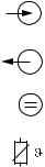
Electrical symbols
Direct Current (DC)
A terminal at which DC is applied or through which DC flows.
Alternating Current (AC)
A terminal at which (sine-form) AC is applied or through which AC flows.
)
*
Ground connecting
A terminal, which, from the user’s point of view, is already grounded using a grounding system.
Protective earth terminal
A terminal which must be grounded before other connections may be set up.
Equipotential connection
+A connection which must be connected to the grounding system of the equipment. This can be, i.e., a potential matching line of a star-shaped grounding system, depending on national or company practice.
/
b
Protective insulation
The equipment is protected by double insulation.
Alarm relay
Input
Output
Constant voltage source
Temperature sensor
6 |
Endress+Hauser |
Smartec S CLD132 |
Identification |
|
|
2 Identification
2.1Device designation
2.1.1Nameplate
Compare the order code on the nameplate (on the Smartec) with the product structure (see below) and check that it agrees with your order.
You can identify the instrument variant by the order code on the nameplate. Under "Codes", you can find the release code for the software upgrade "MRS".
 ENDRESS+HAUSER
SMARTEC S conductivity ind./ Leitfähigkeit ind.
order code / Best.Nr. : CLD 132-PMV130AB2
serial no. / Ser.-Nr. : 1C466C05 G00 Codes: / 8833
measuring range / Messbereich : 10 µS ...2000 mS/cm temperature / Temperatur: -10...+125 °C (+140 °C max. 30 min)
output 1 / Ausgang 1 |
: 0/4...20 mA |
||
output 2 / Ausgang 2 |
: 0/4...20 mA |
||
mains / Netz |
: 230 VAC |
50/60 Hz 7,5 VA |
|
prot. class |
/ Schutzart |
: IP67 |
|
ambient temp. / Umgebungstemperatur : 0...+55 °C
131697-4B
C07-CLD132xx-18-06-00-xx-001.eps
Fig. 1: Nameplate CLD132 (example)
2.1.2Product structure Smartec S CLD132
Version
P Compact version
S Separate transmitter, cable length 20 m / 65.62 ft
WSeparate transmitter, cable length 5 m / 16.41 ft
XSeparate transmitter, cable length 10 m / 32.81 ft
Process connection
MV1 |
Dairy fitting DN 50 (acc. to DIN 11851) |
CS1 |
Clamp connection 2" (acc. to ISO 2852) |
GE1 |
Internal thread G 1 ½ |
VA1 |
Varivent connection DN 40 ... 125 |
AP1 |
APV connection DN 40 ... 100 |
SMS |
SMS connection 2" |
Cable entry
1 |
Cable gland Pg 13.5 |
3 |
Cable gland M 20 x 1.5 |
5 |
Conduit adapter NPT ½ " |
Power supply
0 |
230 V AC |
1 |
115 V AC |
5 |
100 V AC |
8 |
24 V AC / DC |
Current output / communication
AA |
Current output conductivity, without communication |
AB |
Current output conductivity and temperature, without communication |
HA |
HART, current output conductivity |
HB |
HART, current output conductivity and temperature |
PE |
PROFIBUS-PA, no current output |
PF |
PROFIBUS-PA, M 12 connector, no current output |
PPPROFIBUS-DP, no current output
Additional features
1 Basic version with fast temperature measurement
2 Remote parameter set switching with fast temperature measurement 6 Basic version with encapsulated Pt 100 for high loads
7 Remote parameter set switching with encapsulated Pt 100 for high loads
CLD132- |
|
|
|
|
|
|
complete order code |
Endress+Hauser |
7 |
Identification |
Smartec S CLD132 |
|
|
2.1.3Basic version and function extensions
Functions of the basic version |
Options and their functions |
|||
|
|
|
||
• Measurement |
• |
Second current output for temperature (hardware |
||
• |
Calibration of cell constant |
|
option) |
|
• Calibration of residual coupling |
• |
HART communication |
||
• |
Calibration of installation factor |
• |
PROFIBUS communication |
|
• Read instrument parameters |
Remote parameter set switching (software option): |
|||
• |
Linear current output |
|||
• |
Remote switching of max. 4 parameter sets |
|||
• |
Current output simulation |
|||
|
(measuring ranges) |
|||
• |
Service functions |
|
||
• |
Temperature coefficients can be determined |
|||
• |
Temperature compensation selectable (e.g. 1 free |
|||
• |
Temperature compensation selectable (e.g. 4 free |
|||
|
coefficient table) |
|||
|
|
coefficient tables) |
||
• |
Concentration measurement selectable (4 defined |
|
||
• |
Concentration measurement selectable (4 defined |
|||
|
curves, 1 free table) |
|||
|
|
curves, 4 free tables) |
||
• |
Relay as alarm contact |
|
||
• |
Check of measuring system by PCS alarm (live check) |
|||
|
|
|||
|
|
• |
Relay can be configured as alarm or limit contact |
|
|
|
|
|
|
2.2Scope of delivery
The scope of delivery of the compact version inlcudes:
•Smartec S CLD132 compact measuring system with integrated sensor
•Terminal strip set
•Expansion bellows (-*GE1***** versions only)
•Operating Instructions BA 207C/07/en
•Versions with HART communication only:
Operating Instructions Field communication with HART, BA 212C/07/en
•Versions with PROFIBUS interface only:
–Operating Instructions Field communication with PROFIBUS, BA 213C/07/en
–M12 connector (-******PF* versions only)
The scope of delivery of the separate version includes:
•Smartec S CLD132 transmitter
•CLS52 inductive sensor with fixed cable
•Terminal strip set
•Expansion bellows (-*GE1***** versions only)
•Operating Instructions BA 207C/07/en
•Versions with HART communication only:
Operating Instructions Field communication with HART, BA 212C/07/en
•Versions with PROFIBUS interface only:
–Operating Instructions Field communication with PROFIBUS, BA 213C/07/en
–M12 connector (-******PF* versions only)
2.3Certificates and approvals
Declaration of conformity
The product meets the legal requirements of the harmonised European standards.
The manufacturer confirms compliance with the standards by affixing the 4 symbol.
8 |
Endress+Hauser |
Smartec S CLD132 |
Installation |
|
|
3 Installation
3.1Quick installation guide
The following procedure should be followed for a complete measuring point installation:
Compact version:
•Perform an Airset. Install the compact version at the measuring point (see chapter "Mounting CLD132 compact version").
•Connect the compact version as described in the chapter "Electrical connection".
•Start up the compact version as described in the chapter "Commissioning".
Separate version:
•Mount the transmitter (see chapter "Mounting CLD132 separate version").
•If you have not yet installed the sensor at the measuring point, perform an Airset and install the sensor (see the Technical Information of the sensor).
•Connect the sensor to the Smartec S CLD132 as described in the chapter "Electrical connection".
•Connect the transmitter as described in the chapter "Electrical connection".
•Start up the Smartec S CLD132 as described in the chapter "Commissioning".
3.1.1Measuring system
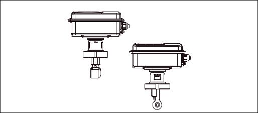
The complete measuring system comprises:
•the Smartec S CLD132 transmitter
•the conductivity sensor Indumax H CLS52 with an integrated temperature sensor and a fixed cable
or
•the compact version with an integrated conductivity sensor
Optional for the separate version: CLK5 extension cable, VBM junction box, mounting kit for pipe installation (see chapter "Accessories")
B
CAL |
+ |
E |
– |
A
C
C07-CLD132xx-14-06-00-xx-001.eps
Fig. 2: Complete measuring systems Smartec S CLD132 as a separate transmitter and compact version with integrated conductivity sensor
ACLS52 conductivity sensor
BSmartec S CLD132
CSmartec S CLD132 as compact version with integrated conductivity sensor
Endress+Hauser |
9 |
Installation |
Smartec S CLD132 |
|
|
3.2Incoming acceptance, transport, storage
•Make sure the packaging is undamaged!
Inform the supplier about damage to the packaging.
Keep the damaged packaging until the matter has been settled.
•Make sure the contents are undamaged!
Inform the supplier about damage to the delivery contents. Keep the damaged products until the matter has been settled.
•Check that the scope of delivery is complete and agrees with your order and the shipping documents.
•The packaging material used to store or to transport the product must provide shock protection and humidity protection. The original packaging offers the best protection. Also, keep to the approved ambient conditions (see "Technical data").
•If you have any questions, please contact your supplier or your sales centre responsible.
3.3Installation conditions
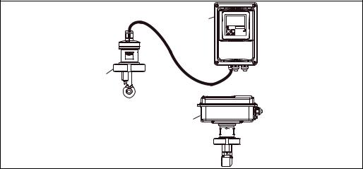
3.3.1Notes on installation
Airset
Perform an Airset before sensor installation (see chapter "Calibration"). Make sure that the instrument is ready for operation, i.e. mains and sensor are connected.
Wall distance
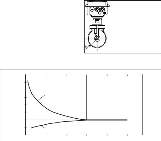
The sensor’s distance from the pipe wall affects the measuring accuracy (see Fig. 4).
In narrow installation conditions, the ion flow in the medium is affected by the pipe walls. This effect is compensated by the so-called installation factor.
When the distance from the wall is sufficient, i.e. a > 15 mm / 0.59", the installation factor
can be ignored (f = 1.00). When the wall distance is lower, the installation factor
increases in the case of electrically insulating pipes (f > 1) while it decreases for electrically conductive pipes (f < 1); see Fig. 4.
C07-CLD132xx-11-06-00-xx-009.eps
The determination of the installation factor is
Fig. 3: Installation CLD132 compact version
described in the chapter "Calibration".
|
|
|
a |
Wall distance |
|
|
f |
0.20 |
0.39 |
0.59 |
0.79 |
0.98 |
a [inch] |
|
|
|
|
|
|
|
1,40 |
|
|
|
|
|
|
|
2 |
|
|
|
|
|
1,20 |
|
|
|
|
|
|
1,00 |
|
|
|
|
|
|
|
1 |
|
|
|
|
|
0,80 |
|
|
|
|
|
a [mm] |
0 |
5 |
10 |
15 |
20 |
25 |
|
|
|
|
|
|
|
C07-CLD132xx-05-06-00-en-001.eps |
Fig. 4: Relationship between installation factor and distance from wall a
1Electrically conductive pipe wall
2Insulating pipe wall
10 |
Endress+Hauser |
Smartec S CLD132 |
Installation |
|
|
3.3.2CLD132 separate version
|
142 / 5.59 |
|
|
/8.86 |
Ø 7 / 0.28 |
6.30 |
|
160/ |
|||
|
|||
225 |
|
|
|
|
|
225 / 8.86 |
|
|
175 / 6.89 |
|
|
|
95/3.74 |
|
|
|
|
mm /inch |
|
|
|
C07-CLD132xx-11-06-00-en-001.EPS |
Fig. 5: CLD132 wall mounting with mounting plate
C07-CLD132xx-11-06-00-en-002.EPS
Fig. 6: CLD132 mounting on pipes (Ø 60 mm / 2.36")
Endress+Hauser |
11 |
Installation |
Smartec S CLD132 |
|
|
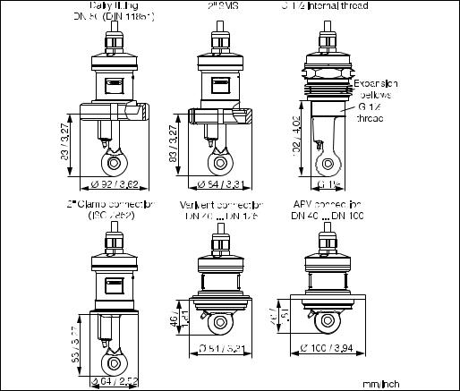
Conductivity sensors for the separate transmitter
CLS52 conductivity sensors with various process connections covering all common installation conditions are available for the separate version.
!Perform an Airset and calibrate the sensor before sensor installation.Note!
C07-CLD132xx-11-06-00-en-003.EPS
Fig. 7: Process connections for CLS52 conductivity sensor
!Note!• Clamp connection
Sensors with clamp connections can be fixed using sheet metal brackets or solid brackets. Sheet metal brackets have a lower dimensional stability, uneven bearing surfaces causing point loads and sometimes sharp edges that can damage the clamp.
We strongly recommend to always use solid brackets because of their higher dimensional stability. Solid brackets may be applied over the total pressure-temperature range (see diagram on page 5).
•Threaded connection
Sensors with threaded connections are supplied with expansion bellows (compensator) to be able to align them in flow direction. The two O-rings (Viton) of the expansion bellows have no sealing function and are not in contact with medium. The process is usually sealed off by PTFE tape on the G 1½ thread.
12 |
Endress+Hauser |
Smartec S CLD132 |
Installation |
|
|
Measuring range
C07-CLD132xx-05-06-00-xx-002.eps |
Fig. 8: CLS52 measuring range
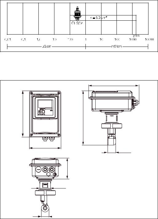
3.3.3CLD 132 compact version
|
225 / 8.86 |
207/8.15 |
(180)*/9.53(7.09)* |
|
242 |
|
142 / 5.59 |
|
35.5 / 1.40 |
|
95/3.74 |
|
49 / 1.93 |
34 / 1.34 |
mm / inch |
C07-CLD132xx-11-06-00-en-004.eps
Fig. 9: Dimensions of CLD132 compact version
Endress+Hauser |
13 |

Installation |
Smartec S CLD132 |
|
|
Connection variants
Various process connections covering all common installation conditions are available for the compact version.
The compact version is installed at the measuring point with the required process connection.
C07-CLD132xx-11-06-00-en-005.eps
Fig. 10: Process connections for the CLD132 compact version
!Note!• Clamp connection
Sensors with clamp connections can be fixed using sheet metal brackets or solid brackets. Sheet metal brackets have a lower dimensional stability, uneven bearing surfaces causing point loads and sometimes sharp edges that can damage the clamp.
We strongly recommend to always use solid brackets because of their higher dimensional stability. Solid brackets may be applied over the total pressure-temperature range (see diagram on page 5).
•Threaded connection
Sensors with threaded connections are supplied with expansion bellows (compensator) to be able to align them in flow direction. The two O-rings (Viton) of the expansion bellows have no sealing function and are not in contact with medium. The process is usually sealed off by PTFE tape on the G 1½ thread.
14 |
Endress+Hauser |

Smartec S CLD132 |
Installation |
|
|
3.4Installation instructions
3.4.1Mounting CLD132 separate version
Wall mounting
For wall mounting, attach the mounting plate to the wall by drilling holes as required. Anchors and screws are to be provided by the operator.
7 / 0.28 |
160/6.30 |
225 / 8.86 |
mm / inch |
C07-CLD132-11-06-00-en-007.eps |
Fig. 11: Wall mounting of CLD132 separate version
Post mounting
A mounting kit for installing the housing on horizontal or vertical posts or pipes (max. Ø 60 mm / Ø 2.36") is available as an accessory (see chapter "Accessories").
C07-CLD132xx-00-06-06-001.eps
Fig. 12: Mounting kit for installing the CLD132 separate version on posts
1.Remove the mounting plate.
2.Insert the holding bars through the pre-drilled holes of the mounting plate and screw the mounting plate onto the transmitter.
3.Use the brackets to install the Smartec S on the post or pipe (Fig. 13).
Endress+Hauser |
15 |

Installation |
Smartec S CLD132 |
|
max. 60 / 2.36 |
|
mm / inch |
|
C07-CLD132xx-11-06-00-en-008.eps |
Fig. 13: Post mounting of CLD132 separate version
3.4.2Mounting CLD132 compact version or CLS52 sensor for separate version
Install the compact version or the CLS52 sensor directly on the pipe or vessel socket via the process connection (depending on ordered version).
!Note!Perform an Airset and calibrate the sensor before installing the compact version or the sensor.
Horizontal flow |
Vertical flow |
 min. DN 40*
Orientation
arrow
min. DN 40*
Flow direction
Flow direction
C07-CLD132-11-06-00-en-006.eps
Fig. 14: Installation of CLD132 compact version
1.When installing the Smartec S CLD132 or the sensor, make sure that the flow opening of the sensor is oriented in the flow direction of the medium. An orientation arrow on the sensor facilitates orientation (see Fig. 14 above).
2.Tighten the flange.
3.For versions with internal thread G 1½, expansion bellows are supplied for length compensation. Thus, the sensor can always be oriented in flow direction.
!Note!• Choose the immersion depth of the sensor in the medium such that the coil body is completely
immersed.
•Please observe the notes on the wall distance in the chapter "Installation conditions".
•Please observe the limits for the medium and ambient temperature when using the compact version (see chapter "Technical data").
16 |
Endress+Hauser |
Smartec S CLD132 |
Installation |
|
|
Sensor positioning: compact version
The sensor in the compact housing must be oriented in the flow direction.
If you need to reorient the sensor in relation to the housing, proceed as follows:
1.Remove the cover.
2.Loosen the screws of the electronics box and carefully remove the box from the housing.
3.Loosen the three sensor fastening screws until the sensor can be turned.
4.Align the sensor and tighten the screws. Do not exceed the maximum torque of 1.5 Nm!
5.Reassemble the transmitter housing in reverse sequence of operations.
!Note!For exact positions of the electronics box and the sensor screws, see the exploded view in the chapter "Spare parts".
A
B
C07-CLD132xx-11-06-05-xx-010.eps
Fig. 15: Sensor orientation in the transmitter housing
AStandard orientation
BSensor turned by 90°
3.5Post-installation check
•After installation, check the measuring system for damages.
•Check the sensor orientation to the flow direction of the medium.
•Check that the coil body of the sensor is completely immersed in the medium.
Endress+Hauser |
17 |

Wiring |
Smartec S CLD132 |
|
|
4 Wiring
4.1 Electrical connection
#Warning!• The electrical connection must only be carried out by a certified electrician.
• Technical personnel must have read and understood the instructions in this manual and must adhere to them.
• Ensure that there is no voltage at the power cable before beginning the connection work.
4.1.1Electrical connection of transmitter
Proceed as follows to connect the Smartec S CLD132:
1. |
Loosen the 4 Phillips screws on the housing |
|
|
cover and remove the cover. |
|
2. |
Remove the cover frame from the terminal |
|
|
blocks. To do this, introduce a screwdriver in |
|
|
the recess (m) according to Fig. 16 and push |
1 |
|
the tab inward (n). |
|
|
# Warning! |
|
|
Do not remove the cover frame while the |
|
|
instrument is energised! |
|
3. |
Thread the cables through the open cable |
1 |
|
glands into the housing according to the |
|
|
terminal assignments in Fig. 17. |
|
4.Connect the power wires according to the terminal assignments in Fig. 18.
5.Connect the alarm contact according to the terminal assignments in Fig. 18.
6.Connect the housing ground.
7.Separate version: Connect the sensor according to the terminal assignments in Fig. 18.
In the case of the separate version, the conductivity sensor CLS52 is connected using the shielded multi-core special cable CLK5. Preparation instructions are supplied with the cable. Use junction box VBM (see chapter "Accessories") to extend the measuring cable. The maximum cable length if extended using a junction box is 55 m.
8.Tighten the cable glands firmly.
2
2
3
4
5
C07-CLD132xx-04-06-00-xx-001.eps
Fig. 16: View of housing with cover removed
1Cover frame
2Fuse
3Removable electronics box
4Terminals
5Housing ground
18 |
Endress+Hauser |

Smartec S CLD132 |
Wiring |
|
|
|
A |
|
B |
3 |
|
|
1 |
2 |
|
1 |
2 |
3 |
|
|
|
|
|
|
5 |
4 |
|
|
6 |
5 |
4 |
|
|
|
|
|
|
C07-CLD132xx-04-06-04-xx-001.eps |
Fig. 17: |
Terminal assignments of cable glands on Smartec S CLD132 |
||||
A |
Separate version |
|
B |
Compact version |
|
1 |
Plug, Pg 13.5, analog output, binary input |
1 |
Plug, Pg 13.5, analog output, digital input |
||
2 |
Cable gland for alarm contact, Pg 13.5 |
2 |
Cable gland for alarm contact, Pg 13.5 |
||
3 |
Cable gland for power supply, Pg 13.5 |
3 |
Cable gland for power supply, Pg 13.5 |
||
4 |
Housing ground |
|
4 |
Housing ground |
|
5 |
Pressure comp. element PCE (Goretex®- filter) |
5 |
Pressure comp. element PCE (Goretex®- filter) |
||
6 |
Cable gland for sensor connection, Pg 9 |
|
|
||
Wiring diagram
C07-CLD132xx-04-06-00-de-003.eps |
Fig. 18: Electrical connection of Smartec S
Endress+Hauser |
19 |

Wiring |
Smartec S CLD132 |
|
|
Connection diagram
|
|
31 |
|
|
84 |
|
|
|
mA |
|
15 |
|
|
|
|
|
|
|
||
|
A |
32 |
Lf |
|
16 |
F |
|
|
|
|
83 |
|
|
|
|
|
|
|
|
|
|
|
33 |
mA |
optional |
S |
|
|
|
|
|
11 |
|
|
|
B |
34 |
|
|
|
|
|
|
|
|
|
|
|
|
|
|
|
|
12 |
G |
|
|
|
|
|
13 |
|
|
|
|
|
|
|
|
|
|
85 |
15 V |
|
|
|
|
C |
86 |
|
|
|
|
|
|
|
|
|
|
|
|
|
93 |
|
|
41 |
|
|
D |
10-50 V |
|
|
42 |
H |
|
|
|
43 |
|||
|
|
94 |
|
|
|
|
|
|
|
|
|
|
|
|
|
81 |
|
|
– |
|
|
|
|
|
|
I |
|
|
E |
10-50 V |
|
|
– |
|
|
|
|
|
|
||
|
|
82 |
|
|
|
|
|
|
|
|
|
|
PE |
|
|
|
|
|
|
C07-CLD132xx-05-06-00-xx-003.eps |
Fig. 19: |
Electrical connection of Smartec S CLD132 |
|
|
|
||
A |
Signal output 1 conductivity |
|
F |
Conductivity sensor |
|
|
B |
Signal output 2 temperature |
|
G |
Temperature sensor |
|
|
C |
Auxiliary power output |
|
H |
Alarm (contact position: no current) |
||
D |
Binary input 2 (MRS1+2) |
|
I |
Power supply |
|
|
E |
Binary input 1 (hold / MRS 3+4) |
|
MRS |
Remote parameter set switching (measuring range |
||
|
|
|
|
|
switching) |
|
Connection of binary inputs |
|
|
|
|
||
|
|
|
A |
B |
|
|
D1 |
D2 |
15 V |
|
85 |
86 |
81 |
82 |
93 |
94 |
S1 S2
C07-CLD132xx-05-06-00-xx-004.eps
Fig. 20: Connection of binary inputs when using external contacts
AAuxiliary power output
BContact inputs D1 and D2
S1 External contacts, not energised
S2 External contacts, not energised
20 |
Endress+Hauser |
Smartec S CLD132 |
Wiring |
|
|
Connection compartment sticker
131082-4A |
|
|
|
|
|
|
|
Sensor |
|
31 |
+ |
|
15 |
|
|
|
Lf |
|
|
32 |
- |
|
84 |
|
33 |
+ |
Temp. |
12 |
WH |
|
|
|
|
|
34 |
- |
(opt.) |
13 |
YE |
|
||||
NC |
|
11 |
GN |
|
85 |
+ |
+15V |
16 |
|
|
|
|
|
|
86 |
- |
10mA |
83 |
|
|
|
|||
93 |
+ |
|
S |
|
|
Bin 2 |
|
|
|
94 |
- |
|
42 |
|
81 |
+ |
|
43 |
|
|
Bin 1 |
|
|
|
82 |
- |
|
41 |
|
NC |
|
|
|
|
|
– |
Mains |
||
|
|
|
||
|
|
|
|
Hilfsenergie |
NC |
|
– |
|
|
C07-CLD132xx-05-06-00-xx-005.eps
Fig. 21: Connection compartment sticker of Smartec S
!Note!The protection class of this instrument is I. The metal housing must be connected to PE.
"Caution!• Terminals designated as NC may not be switched.
• Undesignated terminals may not be switched.
Structure and termination of measuring cable |
|
|
||
Semiconductor |
(84) |
(83) |
|
|
screen |
|
|
|
|
Screen |
|
Screen |
|
|
(15) |
|
(16) |
|
|
|
|
WH |
|
|
|
|
RD |
|
|
GN (11) |
|
|
|
|
WH (12) |
|
BN |
|
|
YE (13) |
|
(unused) |
|
|
|
|
|
|
|
|
CLK5 |
|
|
|
|
|
C07-CLK5xxxx-00-05-00-en-002.eps |
|
C07-CLD132xx-05-06-00-xx-006.eps |
Fig. 22: Structure of CLK5 measuring cable |
Fig. 23: |
Electrical connection of the CLS52 sensor for |
||
|
|
|
|
the separate version |
Endress+Hauser |
21 |
Wiring |
Smartec S CLD132 |
|
|
4.2Post-connection check
After wiring up the electrical connection, carry out the following checks:
Device status and specifications |
Remarks |
|
|
Are the transmitter or the cable externally damaged? |
Visual inspection |
|
|
|
|
Electrical connection |
Remarks |
|
|
Are the installed cables strain-relieved? |
|
|
|
No loops and cross-overs in the cable run? |
|
|
|
Are the signal cables correctly connected acc. to the wiring diagram? |
|
|
|
Are all screw terminals tightened? |
|
|
|
Are all cable entries installed, tightened and sealed? |
|
|
|
Are the PE distributor rails grounded (if present)? |
Grounding at place of installation |
|
|
22 |
Endress+Hauser |
Smartec S CLD132 |
Operation |
|
|
5 Operation
5.1Quick operation guide
You have the following options of operating Smartec S:
•Local operation via operating keys
•Via HART® interface (optional, for corresponding order version) via:
–HART® hand-held terminal or
–PC with HART® modem and Commuwin II software
•Via PROFIBUS PA/DP (optional, for corresponding order version)
PC with a corresponding interface and the Commuwin II software (see "Accessories") or via programmable logic controller (PLC).
!Note!For operation via HART or PROFIBUS PA/DP, read the corresponding chapters in the additional operating instructions:
•PROFIBUS PA/DP, field communication with Smartec S CLD132, BA 213C/07/en
•HART®, field communication with Smartec S CLD132, BA 212C/07/en
The following chapters describe local operation via operating keys.
5.2Display and operating elements
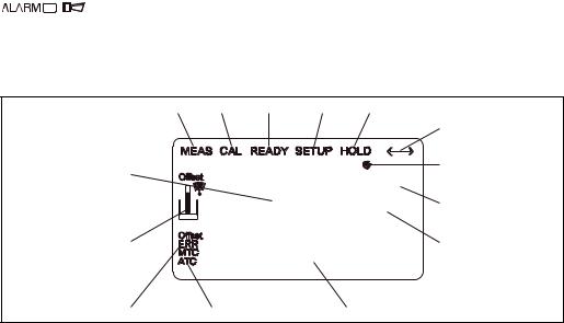
5.2.1Display
LED indicators
Alarm indication for continuous limit violation, temperature sensor failure or system errors (see error list in chapter "Troubleshooting").
Liquid crystal display
1 |
2 |
3 |
4 |
5 |
|
|
|
|
|
|
6 |
14 |
|
|
|
|
7 |
|
2000 |
mS/cm |
|
||
|
|
|
|||
|
|
O213 |
8 |
||
13 |
|
20 |
mA |
|
9 |
|
|
|
|
||
12 |
11 |
|
10 |
|
|
C07-CLD132xx-07-06-00-xx-001.eps
Fig. 24: LCD of Smartec S CLD132
1Measuring mode indicator (normal operation)
2Calibration mode indicator
3Calibration complete indicator
4Setup mode indicator (configuration)
5"Hold" mode indicator (outputs reflect last current status)
6Signal reception indicator for units with communication
7Indication of relay state: d inactive, c active
8In measuring mode: variable measured In setup mode: parameter adjusted
9Function coding display
10In measuring mode: secondary measured value In setup / calibr. mode: e.g. parameter
11Manual / automatic temperature compensation display
12Error indicator
13Sensor symbol, flashes during calibration
14In measuring mode: Main measured valued In setup / calibr. mode: e.g. parameter
Endress+Hauser |
23 |

Operation |
Smartec S CLD132 |
|
|
5.2.2Operating elements
The operating keys are located underneath the housing cover. The display and the alarm LED are visible through the viewing window. For operation, open the housing cover by removing the 4 screws.
1
mS/cm
2000 O213
20 mA |
3 |
 ENDRESS+HAUSER
SMARTEC S
ALARM
CAL +
4
E –
2
C07-CLD132xx-19-06-00-xx-001.eps
Fig. 25: Operating elements of Smartec S CLD132
1Liquid crystal display showing measured values and configuration data
24 operating keys for calibration and instrument configuration
3Field for user labeling
4LED indicator for alarm function
5.2.3Key assignment
CAL key
When the CAL key is pressed, the instrument prompts for the calibration access code:
• Code 22 for calibration
• Code 0 or any other number to view the calibration data
Use the CAL key to acknowledge calibration data and to continue through the calibration process.
ENTER key
When the ENTER key is pressed, the instrument prompts for the setup access code:
• Code 22 for setup and configuration
• Code 0 or any other number to view the configuration data.
The ENTER key has several functions:
•It calls up the setup menus from the measuring mode
•It is used to store (acknowledge) data entered in setup mode
•It is used to move on within function groups
24 |
Endress+Hauser |

Smartec S CLD132 |
Operation |
|
|
PLUS key and MINUS key
In setup mode, the PLUS and MINUS keys have the following functions:
• Selection of function groups
!Note!
To select function groups in the order given in the chapter "Instrument configuration", use the MINUS key.
• Setting of parameters and numeric values
In measuring mode, repeatedly pressing the PLUS key displays the following settings in sequence:
1.Temperature display in °F
2.Hide temperature display
3.Display of uncompensated conductivity value
4.Back to basic setting
In measuring mode, repeatedly pressing the MINUS key displays the following settings in sequence:
1.Display of current measuring range
2.Display of current errors in sequence (max. 10)
3.After all errors are displayed, the standard display is shown again. In function group F, you can define an alarm for each error code.
Escape function
Press the PLUS and MINUS keys simultaneously to return to the main menu. During calibration, this key combination goes directly to the end of calibration. When the PLUS and MINUS keys are pressed once more, the instrument returns to the measuring mode.
Locking the keypad
Pressing the PLUS and ENTER keys simultaneously for minimum 3s locks the keypad against unintentional entries. However, all settings can still be read.
The code prompt displays the code 9999.
Unlocking the keypad
Pressing the CAL and MINUS keys simultaneously for minimum 3s unlocks the keypad.
The code prompt displays the code 0.
Endress+Hauser |
25 |

Operation |
Smartec S CLD132 |
|
|
5.3Local operation
5.3.1Operating concept
Operating modes
Measuring mode: standard mode of operation, displaying current measured values
Calibration mode: |
Setup mode |
execution of |
access to all |
calibration routine |
configuration |
|
settings |
Code
The function groups are selected with the PLUS or MINUS key.
C07-CLD132xx-19-06-00-en-002.eps
Fig. 26: Description of operating modes
!Note!If no key is pressed for 15 min. in setup mode, the instrument automatically switches back to the measuring mode. An active Hold function (Hold at Setup) is then reset.
Access codes
All instrument access codes are fixed, i.e. they cannot be modified. When the instrument requests the access codes, it recognises the difference between codes.
•CAL key + Code 22: access to calibration and offset menus.
•ENTER key + Code 22: access to the configuration menus, allowing configuration and user-specific settings.
•PLUS + ENTER keys: locks the keypad.
•CAL + MINUS keys: unlocks the keypad.
•CAL or ENTER key + any code: access to Read mode, i.e. all settings can be read but not changed.
26 |
Endress+Hauser |
Loading...