


 Loading...
BA00383P/00/EN/08.16
71316872
Valid from software version: 01.00.zz
Products |
Solutions |
Services |
|
|
|
Operating Instructions
Cerabar M
Deltabar M
Deltapilot M
Process pressure / Differential pressure, Flow / Hydrostatic
Cerabar M
Deltabar M
Deltapilot M
Cerabar M, Deltabar M, Deltapilot M
Order code: XXXXX-XXXXXX
1. |
Ser. no.: |
XXXXXXXXXXXX |
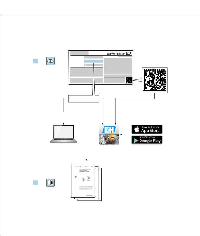
Serial number
2. |
www.endress.com/deviceviewer |
|
Endress+Hauser Operations App |
|||||
|
|
|
|
|
|
|
|
|
|
|
|
|
|
|
|
|
|
|
|
|
|
|
|
|
|
|
|
|
|
|
|
|
|
|
|
|
|
|
|
|
|
|
|
|
|
|
|
|
|
|
|
|
|
|
|
|
|
|
|
|
|
|
3.
A0023555
Make sure the document is stored in a safe place such that it is always available when working on or with the device.
To avoid danger to individuals or the facility, read the "Basic safety instructions" section carefully, as well as all other safety instructions in the document that are specific to working procedures.
The manufacturer reserves the right to modify technical data without prior notice. Your Endress+Hauser distributor will supply you with current information and updates to these Instructions.
2 |
Endress+Hauser |

Cerabar M, Deltabar M, Deltapilot M
Table of contents
1 Document information . . . . . . . . . . . . . . 4
1.1 Document function . . . . . . . . . . . . . . . . . . . . . . . . . . 4 1.2 Symbols used . . . . . . . . . . . . . . . . . . . . . . . . . . . . . . . 4
2 Basic safety instructions . . . . . . . . . . . . . 7
2.1 Requirements concerning the staff . . . . . . . . . . . . . 7 2.2 Designated use . . . . . . . . . . . . . . . . . . . . . . . . . . . . . 7 2.3 Workplace safety . . . . . . . . . . . . . . . . . . . . . . . . . . . 7 2.4 Operational safety . . . . . . . . . . . . . . . . . . . . . . . . . . . 7 2.5 Hazardous area . . . . . . . . . . . . . . . . . . . . . . . . . . . . . 8 2.6 Product safety . . . . . . . . . . . . . . . . . . . . . . . . . . . . . . 8
3 Identification . . . . . . . . . . . . . . . . . . . . . . 9
3.1 Product identification . . . . . . . . . . . . . . . . . . . . . . . . 9 3.2 Device designation . . . . . . . . . . . . . . . . . . . . . . . . . . 9 3.3 Scope of delivery . . . . . . . . . . . . . . . . . . . . . . . . . . 12 3.4 CE mark, Declaration of Conformity . . . . . . . . . . 12
4 Installation . . . . . . . . . . . . . . . . . . . . . . . 13
4.1 Incoming acceptance . . . . . . . . . . . . . . . . . . . . . . 13 4.2 Storage and transport . . . . . . . . . . . . . . . . . . . . . . 13 4.3 Installation conditions . . . . . . . . . . . . . . . . . . . . . 13 4.4 General installation instructions . . . . . . . . . . . . . 14 4.5 Installing Cerabar M . . . . . . . . . . . . . . . . . . . . . . . 15 4.6 Installing Deltabar M . . . . . . . . . . . . . . . . . . . . . . 25 4.7 Installing Deltapilot M . . . . . . . . . . . . . . . . . . . . . 33
4.8Installing profile seal for universal process adapter
38
4.9 Closing the housing cover . . . . . . . . . . . . . . . . . . 38 4.10 Post-installation check . . . . . . . . . . . . . . . . . . . . . 38
5 |
Electrical connection . . . . . . . . . . . . . . . |
39 |
5.1 |
Connecting the device . . . . . . . . . . . . . . . . . . . . . |
39 |
5.2 |
Connecting the measuring unit . . . . . . . . . . . . . . |
40 |
5.3 |
Potential equalization . . . . . . . . . . . . . . . . . . . . . . |
41 |
5.4 |
Overvoltage protection (optional) . . . . . . . . . . . . |
42 |
5.5 |
Post-connection check . . . . . . . . . . . . . . . . . . . . . |
44 |
6 |
Operation. . . . . . . . . . . . . . . . . . . . . . . . . |
45 |
6.1 |
Operating options . . . . . . . . . . . . . . . . . . . . . . . . . |
45 |
6.2 |
Operation without an operating menu . . . . . . . |
46 |
6.3 |
Operation with an operating menu . . . . . . . . . . |
48 |
6.4 |
PROFIBUS PA communication protocol . . . . . . |
57 |
7 |
Commissioning without an operating |
|
|
menu . . . . . . . . . . . . . . . . . . . . . . . . . . . . |
82 |
7.1 |
Function check . . . . . . . . . . . . . . . . . . . . . . . . . . . |
82 |
7.2 |
Position adjustment . . . . . . . . . . . . . . . . . . . . . . . |
82 |
8 Commissioning with an operating menu (onsite display/FieldCare) . . . . . . . . . . 84
8.1 Function check . . . . . . . . . . . . . . . . . . . . . . . . . . . . 84 8.2 Commissioning . . . . . . . . . . . . . . . . . . . . . . . . . . . . 85 8.3 Position zero adjustment . . . . . . . . . . . . . . . . . . . . 86
8.4Level measurement (Cerabar M and Deltapilot M) 87
8.5 Linearization . . . . . . . . . . . . . . . . . . . . . . . . . . . . . . 97 8.6 Pressure measurement . . . . . . . . . . . . . . . . . . . 101
8.7Differential pressure measurement (Deltabar M) . 102
8.8 Flow measurement (Deltabar M) . . . . . . . . . . . 104 8.9 Level measurement (Deltabar M) . . . . . . . . . . . 107 8.10 Overview of the onsite display operating menu . . .
119
8.11 Description of parameters . . . . . . . . . . . . . . . . . 127 8.12 Saving or duplicating device data . . . . . . . . . . . 148
9 Commissioning via Class 2 master (FieldCare) . . . . . . . . . . . . . . . . . . . . . . 149
9.1 Function check . . . . . . . . . . . . . . . . . . . . . . . . . . 149 9.2 Commissioning . . . . . . . . . . . . . . . . . . . . . . . . . . 150 9.3 Output value (Out Value) . . . . . . . . . . . . . . . . . . 151
9.4Electrical differential pressure measurement with
gauge pressure sensors (Cerabar M or Deltapilot M) 153
9.5 Description of parameters . . . . . . . . . . . . . . . . . 155 9.6 Saving or duplicating device data . . . . . . . . . . . 202
10 Maintenance . . . . . . . . . . . . . . . . . . . . 203
10.1 Cleaning instructions . . . . . . . . . . . . . . . . . . . . . 203 10.2 Exterior cleaning . . . . . . . . . . . . . . . . . . . . . . . . . 203
11 Troubleshooting . . . . . . . . . . . . . . . . . 204
11.1 Messages . . . . . . . . . . . . . . . . . . . . . . . . . . . . . . . 204 11.2 Response of outputs to errors . . . . . . . . . . . . . . 207 11.3 Repair . . . . . . . . . . . . . . . . . . . . . . . . . . . . . . . . . . 208 11.4 Repair of Ex-certified devices . . . . . . . . . . . . . . 208 11.5 Spare Parts . . . . . . . . . . . . . . . . . . . . . . . . . . . . . . 209 11.6 Return . . . . . . . . . . . . . . . . . . . . . . . . . . . . . . . . . 209 11.7 Disposal . . . . . . . . . . . . . . . . . . . . . . . . . . . . . . . . 209 11.8 Software history . . . . . . . . . . . . . . . . . . . . . . . . . 209
12 Technical data . . . . . . . . . . . . . . . . . . . 210 Index . . . . . . . . . . . . . . . . . . . . . . . . . . . 211
Endress+Hauser |
3 |
Document information |
Cerabar M, Deltabar M, Deltapilot M |
|
|
1 Document information
1.1Document function
These Operating Instructions contain all the information that is required in various phases of the life cycle of the device: from product identification, incoming acceptance and storage, to mounting, connection, operation and commissioning through to troubleshooting, maintenance and disposal.
1.2Symbols used
1.2.1Safety symbols
Symbol Meaning
DANGER!
DANGER This symbol alerts you to a dangerous situation. Failure to avoid this situation will result in
A0011189-DE seriousor fatal injury.
WARNING!
WARNING This symbol alerts you to a dangerous situation. Failure to avoid this situation can result in
A0011190-DE seriousor fatal injury.
CAUTION!
CAUTION This symbol alerts you to a dangerous situation. Failure to avoid this situation can result in
A0011191-DE minoror medium injury.
NOTICE!
NOTICE This symbol contains information on procedures and other facts which do not result in
A0011192-DE personalinjury.
1.2.2Electrical symbols
Symbol |
Meaning |
Symbol |
Meaning |
||
|
|
|
|
|
|
|
|
|
Direct current |
|
Alternating current |
|
|
|
|
|
|
|
|
|
Direct current and alternating current |
|
Ground connection |
|
|
|
|
) |
A grounded terminal which, as far as |
|
|
|
|
|
the operator is concerned, is grounded |
|
|
|
|
|
via a grounding system. |
|
|
|
|
|
|
|
|
|
Protective ground connection |
|
Equipotential connection |
|
|
|
A terminal which must be connected |
|
A connection that has to be connected |
|
|
|
to ground prior to establishing any |
|
to the plant grounding system: This |
|
|
|
other connections. |
|
may be a potential equalization line or |
|
|
|
|
|
a star grounding system depending on |
|
|
|
|
|
national or company codes of practice. |
|
|
|
|
|
|
1.2.3Tool symbols
Symbol |
Meaning |
|
Allen key |
A0011221
Hexagon wrench
A0011222
4 |
Endress+Hauser |
Cerabar M, Deltabar M, Deltapilot M |
Document information |
|
|
1.2.4Symbols for certain types of information
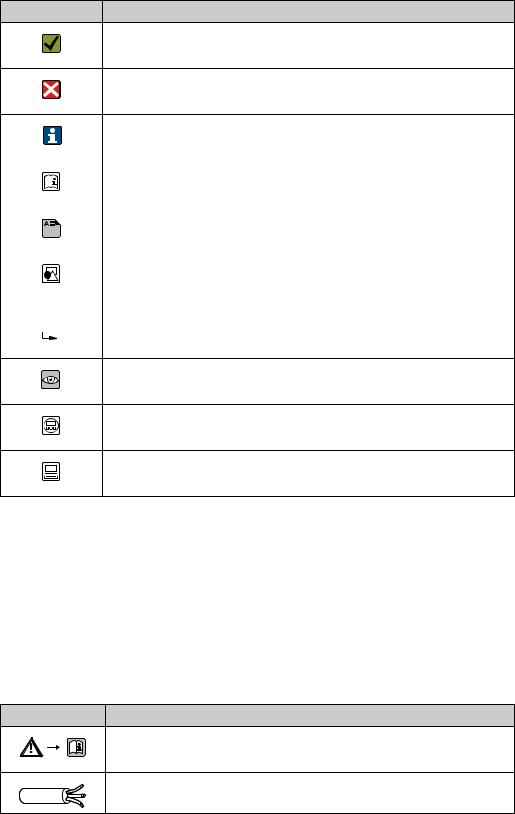
Symbol Meaning
Permitted
Indicates procedures, processes or actions that are permitted.
A0011182
Forbidden
Indicates procedures, processes or actions that are forbidden.
A0011184
|
|
|
|
|
|
|
Tip |
|
|
|
|
|
|
|
Indicates additional information. |
|
|
|
|
|
|
A0011193 |
|
|
|
|
|
|
|
|
|
|
|
|
|
|
|
|
Reference to documentation |
|
|
|
|
|
|
A0015482 |
|
|
|
|
|
|
|
|
|
|
|
|
|
|
|
|
Reference to page |
|
|
|
|
|
|
A0015484 |
|
|
|
|
|
|
|
|
|
|
|
|
|
|
|
|
|
|
|
|
|
|
|
|
|
|
|
|
|
|
|
|
|
|
|
|
|
|
|
|
Reference to graphic |
|
|
|
|
|
|
A0015487 |
|
|
|
|
|
|
|
|
|
|
|
, |
|
, ... |
Series of steps |
||
1. |
2. |
||||||
|
|
|
|
|
|
|
|
|
|
|
|
|
|
|
Result of a sequence of actions |
A0018343
Visual inspection
A0015502
Indicates how to navigate to the parameter using the display and operating module
A0015502
Indicates how to navigate to the parameter using operating tools (e.g. FieldCare)
A0015502
1.2.5Symbols in graphics
|
Symbol |
Meaning |
|||
|
|
|
|
|
|
1, 2, 3, 4, ... |
Item numbers |
||||
|
|
|
|
|
|
|
|
, |
|
, ... |
Series of steps |
1. |
2. |
||||
|
|
|
|
|
|
A, B, C, D, ... |
Views |
||||
|
|
|
|
|
|
1.2.6Symbols at the device
Symbol Meaning
Safety instructions
Observe the safety instructions contained in the associated Operating Instructions.
|
A0019159 |
|
Connecting cable immunity to temperature change |
t>85°C |
Indicates that the connecting cables have to withstand a temperature of 85°C at least. |
Endress+Hauser |
5 |
Document information |
Cerabar M, Deltabar M, Deltapilot M |
|
|
1.2.7Registered trademarks
KALREZ®, VITON®, TEFLON®
Registered label of E.I. Du Pont de Nemours & Co., Wilmington, USA
TRI-CLAMP®
Registered label of Ladish & Co., Inc., Kenosha, USA
PROFIBUS PA®
Trademark of the PROFIBUS User Organization, Karlsruhe, Germany
GORE-TEX®
Registered label of W.L. Gore & Associates, Inc., USA
6 |
Endress+Hauser |
Cerabar M, Deltabar M, Deltapilot M |
Basic safety instructions |
|
|
2 Basic safety instructions
2.1Requirements concerning the staff
The personnel for installation, commissioning, diagnostics and maintenance must fulfill the following requirements:
•Trained, qualified specialists: must have a relevant qualification for this specific function and task
•Are authorized by the plant owner/operator
•Are familiar with federal/national regulations
•Before beginning work, the specialist staff must have read and understood the instructions in the Operating Instructions and supplementary documentation as well as in the certificates (depending on the application)
•Following instructions and basic conditions
The operating personnel must fulfill the following requirements:
•Being instructed and authorized according to the requirements of the task by the facility's owner-operator
•Following the instructions in these Operating Instructions
2.2Designated use
The Cerabar M is a pressure transmitter for measuring level and pressure.
The Deltabar M is a differential pressure transmitter for measuring differential pressure, flow and level.
The Deltapilot M is a hydrostatic pressure sensor for measuring level and pressure.
2.2.1Incorrect use
The manufacturer is not liable for damage caused by improper or non-designated use. Verification for borderline cases:
For special fluids and fluids for cleaning, Endress+Hauser is glad to provide assistance in verifying the corrosion resistance of fluid-wetted materials, but does not accept any warranty or liability.
2.3Workplace safety
For work on and with the device:
•Wear the required personal protective equipment according to federal/national regulations.
•Switch off the supply voltage before connecting the device.
2.4Operational safety
Risk of injury!
Operate the device in proper technical condition and fail-safe condition only.
The operator is responsible for interference-free operation of the device.
Only disassemble the device in pressurless condition!
Conversions to the device
Unauthorized modifications to the device are not permitted and can lead to unforeseeable dangers:
If, despite this, modifications are required, consult with Endress+Hauser.
Repair
To ensure continued operational safety and reliability,
Endress+Hauser |
7 |
Basic safety instructions |
Cerabar M, Deltabar M, Deltapilot M |
|
|
Carry out repairs on the device only if they are expressly permitted.
Observe federal/national regulations pertaining to repair of an electrical device.
Use original spare parts and accessories from Endress+Hauser only.
2.5Hazardous area
To eliminate a danger for persons or for the facility when the device is used in the hazardous area (e.g. explosion protection, pressure vessel safety):
•Based on the nameplate, check whether the ordered device is permitted for the intended use in the hazardous area.
•Observe the specifications in the separate supplementary documentation that is an integral part of these Instructions.
2.6Product safety
This measuring device is designed in accordance with good engineering practice to meet state-of-the- art safety requirements, has been tested, and left the factory in a condition in which they are safe to operate. It fulfills general safety requirements and legal requirements. It also conforms to the EC directives listed in the device-specific EC declaration of conformity. Endress+Hauser confirms this fact by applying the CE mark.
8 |
Endress+Hauser |
Cerabar M, Deltabar M, Deltapilot M |
Identification |
|
|
3 Identification
3.1Product identification
The following options are available for identification of the measuring device:
•Nameplate specifications
•Order code with breakdown of the device features on the delivery note
•Enter serial numbers from nameplates in W@M Device Viewer (www.endress.com/deviceviewer): All information about the measuring device is displayed.
For an overview of the technical documentation provided, enter the serial number from the nameplates in the W@M Device Viewer (www.endress.com/deviceviewer).
3.2Device designation
3.2.1Nameplate
•The MWP (maximum working pressure) is specified on the nameplate. This value refers to a reference temperature of 20°C (68°F) or 100°F (38°C) for ANSI flanges.
•The pressure values permitted at higher temperatures can be found in the following standards:
–EN 1092-1: 2001 Tab. 18 1)
–ASME B 16.5a – 1998 Tab. 2-2.2 F316
–ASME B 16.5a – 1998 Tab. 2.3.8 N10276
–JIS B 2220
•The test pressure corresponds to the over pressure limit (OPL) of the device = MWP x 1.5
2).
•The Pressure Equipment Directive (EC Directive 97/23/EC) uses the abbreviation "PS". The abbreviation "PS" corresponds to the MWP (maximum working pressure) of the measuring device.
1)With regard to their stability-temperature property, the materials 1.4435 and 1.4404 are grouped together under 13EO in EN 1092-1 Tab. 18. The chemical composition of the two materials can be identical.
2)The equation does not apply for PMP51 and PMP55 with a 40 bar (600 psi) or a 100 bar (1500 psi) measuring cell.
Endress+Hauser |
9 |

Identification |
Cerabar M, Deltabar M, Deltapilot M |
|
|
Aluminum housing
|
Made in Germany, D-79689 Maulburg |
|
|
|
Mat.: |
17 |
|
||
|
|
1 |
|
|
|
|
|
||
|
|
2 |
|
|
|
3 |
|
|
|
|
Order code: |
|
4 |
Ser. no.: |
|
|
|||
|
Ext. order code: |
|
|
|
|
18 |
|
||
|
MWP |
5 |
|
6 9 |
Span |
7 10 |
|
||
250002755-C |
|
|
250002756-E |
||||||
P |
8 |
U= |
L= |
|
|||||
|
11 |
13 |
ex works FW: |
14 |
16 |
18 |
|||
|
|
Dev.Rev.: |
15 |
||||||
12 |
|
|
|
|
|||||
|
|
|
|
|
|
|
|
|
|
|
|
|
|
|
|
|
|
|
A0030017 |
Fig. 1: |
Nameplate |
|
|
|
|
|
|
||
1Device name
2Order code (for re-orders)
3Serial number (for identification)
4Extended order code (complete)
5MWP (maximum working pressure)
6Electronic version (output signal)
7Min./max. span
8Nominal measuring range
9Supply voltage
10Unit of length
11ID number of notified body with regard to ATEX (optional)
12ID number of notified body with regard to Pressure Equipment Directive (optional)
13Approvals
14Device version
15Software version
16Degree of protection
17Wetted materials
18Approval-specific information
Devices suitable for oxygen applications are fitted with an additional nameplate.
Bei Sauerstoffeinsatz/ for oxygen service
Pmax |
1 |
|
|
|
|
|
|
|
Tmax |
|
|
2 |
|
|
3 |
||
|
|
|||||||
|
|
|
|
|
|
|
|
|
A0030019
Fig. 2: Additional nameplate for devices suitable for oxygen applications
1Maximum pressure for oxygen applications
2Maximum temperature for oxygen applications
3Layout identification of the nameplate
10 |
Endress+Hauser |
Cerabar M, Deltabar M, Deltapilot M |
Identification |
|
|
Stainless steel housing, hygienic
1 |
Made in Germany, |
|
D-79689 Maulburg |
||
Order code: |
|
2 |
Ser. no.: |
3 |
4 |
Ext. order code: |
4 |
|
|
|
|
|
4 |
-A |
p |
5 |
002757 |
MWP |
6 |
|
L= |
7 |
|
ex works FW |
|
|
|
8 |
|
16 |
U= |
|
9 |
Dev.Rev.: |
|
Span |
|
10 |
|
17 |
Mat.: |
|
11 |
12 |
|
|
|
|||
|
13 |
12 |
18 |
-C |
14 |
|
15 |
|
002758 |
|
|
|
||
A0030021
Fig. 3: Nameplate for Cerabar M and Deltapilot M
1Device name
2Order code (for re-orders)
3Serial number (for identification)
4Extended order code (complete)
5Nominal measuring range
6MWP (maximum working pressure)
7Length data
8Electronic version (output signal)
9Supply voltage
10Min./max. span
11Wetted materials
12Approval-specific information
13ID number of notified body with regard to ATEX (optional)
14ID number of notified body with regard to Pressure Equipment Directive (optional)
15Approvals
16Software version
17Device version
18Degree of protection
Devices with certificates are fitted with an additional plate.
1
1
002759-B
A0030024
Fig. 4: Additional nameplate for devices with certificates 1 Approval-specific information
3.2.2Identifying the sensor type
In the case of gauge pressure sensors, the "Pos. zero adjust" parameter appears in the operating menu ("Setup" -> "Pos. zero adjust").
In the case of absolute pressure sensors, the "Calib. offset" parameter appears in the operating menu ("Setup" -> "Calib. offset").
Endress+Hauser |
11 |
Identification |
Cerabar M, Deltabar M, Deltapilot M |
|
|
3.3Scope of delivery
The scope of delivery comprises:
•Device
•Optional accessories
Documentation supplied:
•The Operating Instructions BA00383P is available on the Internet.See: www.endress.com Download
•Brief Operating Instructions: KA01031P Cerabar M / KA01028P Deltabar M / KA01034P Deltapilot M
•Final inspection report
•Additional Safety Instructions for ATEX, IECEx and NEPSI devices
•Optional: factory calibration form, test certificates
3.4CE mark, Declaration of Conformity
The devices are designed to meet state-of-the-art safety requirements, have been tested and left the factory in a condition in which they are safe to operate. The devices comply with the applicable standards and regulations as listed in the EC Declaration of Conformity and thus comply with the statutory requirements of the EC Directives. Endress+Hauser confirms the conformity of the device by affixing to it the CE mark.
12 |
Endress+Hauser |

Cerabar M, Deltabar M, Deltapilot M |
Installation |
|
|
4 Installation
4.1Incoming acceptance
•Check the packaging and the contents for damage.
•Check the shipment, make sure nothing is missing and that the scope of supply matches your order.
4.2Storage and transport
4.2.1Storage
The device must be stored in a dry, clean area and protected against damage from impact (EN 837-2).
Storage temperature range:
See Technical Information for Cerabar M TI00436P / Deltabar M TI00434P / Deltapilot M TI00437P.
4.2.2Transport
! WARNING
Incorrect transportation
Housing, diaphragm and capillaries may become damaged, and there is a risk of injury!
Transport the measuring device to the measuring point in its original packaging or by the process connection.
Follow the safety instructions and transport conditions for devices weighing more than 18 kg (39.6 lbs).
Do not use capillaries as a carrying aid for the diaphragm seals.
4.3Installation conditions
4.3.1Dimensions
For dimensions, please refer to the Technical Information for Cerabar M TI00436P / Deltabar M TI00434P / Deltapilot M TI00437P, "Mechanical construction" section.
Endress+Hauser |
13 |

Installation |
Cerabar M, Deltabar M, Deltapilot M |
|
|
4.4General installation instructions
•Devices with a G 1 1/2 thread:
When screwing the device into the tank, the flat seal has to be positioned on the sealing surface
of the process connection. To avoid additional strain on the process isolating diaphragm, the thread should never be sealed with hemp or similar materials.
•Devices with NPT threads:
–Wrap Teflon tape around the thread to seal it.
–Tighten the device at the hexagonal bolt only. Do not turn at the housing.
–Do not overtighten the thread when screwing. Max. torque: 20 to 30 Nm (14.75 to 22.13 lbf ft)
4.4.1Mounting sensor modules with PVDF thread
! WARNING
Risk of damage to process connection!
Risk of injury!
Sensor modules with PVDF process connections with threaded connection must be installed with the mounting bracket provided!
!WARNING
Material fatigue from pressure and temperature!
Risk of injury if parts burst! The thread can become loose if exposed to high pressure and temperatures.
The integrity of the thread must be checked regularly and the thread may need to be retightened with the maximum tightening torque of 7 Nm (5.16 lbf ft). Teflon tape is recommended for sealing the ½" NPT thread.
14 |
Endress+Hauser |
Cerabar M, Deltabar M, Deltapilot M |
Installation |
|
|
4.5Installing Cerabar M
•Due to the orientation of the Cerabar M, there may be a shift in the zero point, i.e. when the container is empty or partially full, the measured value does not display zero. You can correct this zero point shift ä 47, Chap. "Function of the operating elements" or
ä 86, Chap. 8.3 "Position zero adjustment".
•For PMP55, please refer to Section 4.5.2 "Installation instructions for devices with diaphragm seals – PMP55", ä 18.
•Endress+Hauser offers a mounting bracket for installing on pipes or walls.
ä 22, Chap. 4.5.5 "Wall and pipe mounting (optional)".
4.5.1Installation instructions for devices without diaphragm seals – PMP51, PMC51
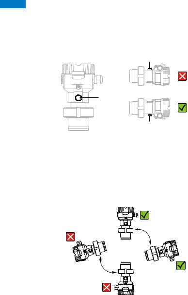
NOTICE
Damage to the device!
If a heated Cerabar M is cooled during the cleaning process (e.g. by cold water), a vacuum develops for a short time, whereby moisture can penetrate the sensor through the pressure compensation (1).
If this is the case, mount the Cerabar M with the pressure compensation (1) pointing downwards.
1
1 |
1
•Keep the pressure compensation and GORE-TEX® filter (1) free from contamination.
•Cerabar M transmitters without diaphragm seals are mounted as per the norms for a manometer (DIN EN 837-2). We recommend the use of shutoff devices and siphons. The orientation depends on the measuring application.
•Do not clean or touch process isolating diaphragms with hard or pointed objects.
•The device must be installed as follows in order to comply with the cleanability requirements of the ASME-BPE (Part SD Cleanability):
Endress+Hauser |
15 |

Installation |
Cerabar M, Deltabar M, Deltapilot M |
|
|
Pressure measurement in gases
1
2
A0028473
Fig. 5: Measuring arrangement for pressure measurement in gases
1Cerabar M
2Shutoff device
Mount the Cerabar M with the shutoff device above the tapping point so that any condensate can flow into the process.
Pressure measurement in steams
1
2
1
2
4
3
A0028474
Fig. 6: Measuring arrangement for pressure measurement in steams
1Cerabar M
2Shutoff device
3U-shaped siphon
4Circular siphon
•Mount Cerabar M with siphon above the tapping point.
•Fill the siphon with liquid before commissioning.
The siphon reduces the temperature to almost the ambient temperature.
16 |
Endress+Hauser |

Cerabar M, Deltabar M, Deltapilot M |
Installation |
|
|
Pressure measurement in liquids
1
2
3
A0028491
Fig. 7: Measuring arrangement for pressure measurement in liquids
1Cerabar M
2Shutoff device
• Mount Cerabar M with shutoff device below or at the same level as the tapping point.
Level measurement
A0028492 |
Fig. 8: Measuring arrangement for level
•Always install the Cerabar M below the lowest measuring point.
•Do not mount the device in the filling curtain or at a point in the tank which could be affected by pressure pulses from an agitator.
•Do not mount the device in the suction area of a pump.
•The calibration and functional test can be carried out more easily if you mount the device downstream of a shutoff device.
Endress+Hauser |
17 |

Installation |
Cerabar M, Deltabar M, Deltapilot M |
|
|
4.5.2Installation instructions for devices with diaphragm seals – PMP55
•Cerabar M devices with diaphragm seals are screwed in, flanged or clamped, depending on the type of diaphragm seal.
•Please note that the hydrostatic pressure of the liquid columns in the capillaries can cause zero point shift. The zero point shift can be corrected.
•Do not clean or touch the process isolating diaphragm of the diaphragm seal with hard or pointed objects.
•Do not remove process isolating diaphragm protection until shortly before installation.
NOTICE
Improper handling!
Damage to the device!
A diaphragm seal and the pressure transmitter together form a closed, oil-filled calibrated system. The fill fluid hole is sealed and may not be opened.
When using a mounting bracket, sufficient strain relief must be ensured for the capillaries in order to prevent the capillary bending down (bending radius 100 (3.94 in)).
Please observe the application limits of the diaphragm seal filling oil as detailed in the Technical Information for Cerabar M TI00436P, "Planning instructions for diaphragm seal systems" section.
NOTICE
In order to obtain more precise measurement results and to avoid a defect in the device, mount the capillaries as follows:
Vibration-free (in order to avoid additional pressure fluctuations)
Not in the vicinity of heating or cooling lines
Insulate if the ambient temperature is below or above the reference temperature
With a bending radius of 100 mm (3.94 in).
Do not use the capillaries as a carrying aid for the diaphragm seals!
18 |
Endress+Hauser |
Cerabar M, Deltabar M, Deltapilot M |
Installation |
|
|
Vacuum application
For applications under vacuum, Endress+Hauser recommends mounting the pressure transmitter below the diaphragm seal. This prevents vacuum loading of the diaphragm seal caused by the presence of fill fluid in the capillary.
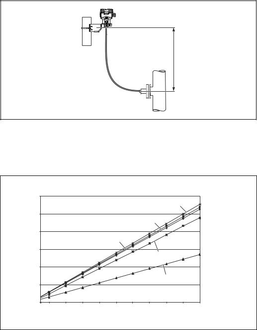
When the pressure transmitter is mounted above the diaphragm seal, the maximum height difference H1 in accordance with the illustrations below must not be exceeded.
H1
A0023994
Fig. 9: Installation above the lower diaphragm seal
The maximum height difference depends on the density of the filling oil and the smallest ever pressure that is permitted to occur at the diaphragm seal (empty vessel), see illustration below:
|
[m] |
|
|
|
|
|
|
|
|
|
|
|
12.0 |
|
|
|
|
|
|
|
|
|
|
|
|
|
|
|
|
|
|
|
1 |
|
|
|
10.0 |
|
|
|
|
|
|
|
|
|
|
|
|
|
|
|
|
|
2 |
|
|
|
|
|
8.0 |
|
|
|
|
|
|
|
|
|
|
|
|
|
|
|
3 |
|
|
|
|
|
|
A |
6.0 |
|
|
|
|
|
|
|
|
|
|
|
|
|
|
|
|
|
|
4 |
|
|
|
|
4.0 |
|
|
|
|
|
|
|
|
|
|
|
2.0 |
|
|
|
|
|
|
5 |
|
|
|
|
|
|
|
|
|
|
|
|
|
|
|
|
0.0 |
|
|
|
|
|
|
|
|
|
|
|
50 100 |
200 |
300 |
400 |
500 |
600 |
700 |
800 |
900 |
1000 |
[mbarabs] |
|
|
|
|
|
B |
|
|
|
|
|
|
A0023986-en
Fig. 10: Diagram of maximum installation height above the lower diaphragm seal for vacuum applications depending on the pressure at the diaphragm seal on the positive side
AHeight difference H1
BPressure at diaphragm seal 1 Low temperature oil
2 Vegetable oil
3 Silicone oil
4 High-temperature oil
5 Inert oil
Endress+Hauser |
19 |

Installation |
Cerabar M, Deltabar M, Deltapilot M |
|
|
Mounting with temperature isolator
Endress+Hauser recommends the use of temperature isolators in the event of constant extreme medium temperatures which lead to the maximum permissible electronics temperature of +85 °C (+185°F) being exceeded.
Depending on the filling oil used, diaphragm seal systems with temperature isolators can be used for maximum temperatures of up to 400 °C (+752 °F). For the temperature application limits, see technical Information, "Diaphragm seal filling oils" section.
To minimize the influence of rising heat, Endress+Hauser recommends the device be mounted horizontally or with the housing pointing downwards. The additional installation height also brings about a maximum zero point shift of 21 mbar (0.315 psi) due to the hydrostatic column in the temperature isolator. You can correct this zero point shift at the device.
The temperature restrictions are lowest with an insulation height of 30 mm (1.18 inch). Full insulation exhibits virtually the same behavior as no insulation!
The temperature limits with an insulation height of 30 mm (1.18 inch) are illustrated in the following graphic.
B [°F] Tp [°C]
G
B |
A |
|
1 |
|
2 |
C
D E F
+752 |
+400 |
|
|
|
|
|
|
|
|
|
+662 |
+350 |
|
|
|
|
|
|
|
|
|
+572 |
+300 |
|
|
|
|
|
|
|
|
|
+482 |
+250 |
|
|
|
|
|
|
|
|
|
+392 |
+200 |
|
|
|
|
|
|
|
|
|
+302 |
+150 |
|
|
|
|
|
|
|
|
|
+212 |
+100 |
|
|
|
|
|
|
|
|
|
+122 |
+50 |
|
|
|
|
|
|
|
|
|
+32 |
0 |
|
|
|
|
|
|
|
|
|
-58 |
-50 |
|
|
|
|
|
|
|
|
|
-148 |
-100 |
|
|
0 |
|
|
|
|
|
[°C] |
|
-60 |
-40 |
-20 |
+20 |
+40 |
+60 |
+80 |
+100 |
Ta |
|
|
|
|
|
|
|
|
|
|
|
|
|
-76 |
-40 |
-4 |
+32 |
+68 |
+104 |
+140 |
+176 |
|
[°F] |
|
+212 |
A |
||||||||
|
|
|
|
|
|
|
|
|
|
A0031354
Fig. 11:
AAmbient temperature: 85 °C (185 °F)
BProcess temperature: max. 400 °C (752 °F), depending on the filling oil used
CDevice with temperature isolator, material 316L (1.4404)
DWithout isolation
EMaximum isolation
F30 mm (1.18. inch) isolation
GWithout isolation, maximum isolation, 30 mm (1.18. inch) isolation
1Isolation heigth 30 mm (1.18. inch)
2Isolation material
20 |
Endress+Hauser |
Cerabar M, Deltabar M, Deltapilot M |
Installation |
|
|
4.5.3Seal for flange mounting
NOTICE
Corrupted measurement results.
The seal is not allowed to press against the process isolating diaphragm as this could affect the measurement result.
Ensure that the seal is not touching the process isolating diaphragm.
|
1 |
2 |
|
|
A0017743 |
Fig. 12: |
|
|
1 |
Process isolating diaphragm |
|
2 |
Seal |
|
4.5.4Thermal insulation – PMP55
The PMP55 may only be insulated up to a certain height. The maximum permitted insulation height is indicated on the devices and applies to an insulation material with a heat conductivity 0.04 W/(m x K) and to the maximum permitted ambient and process temperature. The data were determined under the most critical application "quiescent air".
A
1 2
B
A0020474
Fig. 13: Maximum permitted insulation height, here indicated on a PMP55 with a flange
AAmbient temperature: 70 °C (158°F)
BProcess temperature: max. 400 °C (752°F), depending on the diaphragm seal filling oil used 1 Maximum permitted insulation height
2 Insulation material
Endress+Hauser |
21 |

Installation |
Cerabar M, Deltabar M, Deltapilot M |
|
|
4.5.5Wall and pipe mounting (optional)
Endress+Hauser offers a mounting bracket for installation on pipes or walls (for pipe diameters from 1 ¼" to 2").
(2.76) |
3.39) |
70 |
86( |
|
122 (4.8) |
|
158 (6.22) |
|
ø42...60 (1.65...2.36) |
(2.05) |
(0.24) |
52 |
ø6 |
|
140 (5.51) |
|
175 (6.89) |
A0028493
Engineering unit mm (in)
Please note the following when mounting:
•Devices with capillary tubes: mount capillaries with a bending radius 100 mm (3.94 in).
•When mounting on a pipe, tighten the nuts on the bracket uniformly with a torque of at least 5 Nm (3.69 lbs ft).
22 |
Endress+Hauser |

Cerabar M, Deltabar M, Deltapilot M |
Installation |
|
|
4.5.6Assembling and mounting the "separate housing" version
7
6
5
4
3
2
1
7
r 120 (4.72)
A0028494
Fig. 14: "Separate housing" version
1In the case of the "separate housing" version, the sensor is delivered with the process connection and cable ready mounted.
2Cable with connection jack
3Pressure compensation
4Connector
5Locking screw
6Housing mounted with housing adapter, included
7Mounting bracket provided, suitable for pipe and wall mounting (for pipe diameters from 1 ¼" up to 2")
Engineering unit mm (in)
Assembly and mounting
1.Insert the connector (item 4) into the corresponding connection jack of the cable (item 2).
2.Plug the cable into the housing adapter (item 6).
3.Tighten the locking screw (item 5).
4.Mount the housing on a wall or pipe using the mounting bracket (item 7).
When mounting on a pipe, tighten the nuts on the bracket uniformly with a torque of at least 5 Nm (3.69 lbs ft).
Mount the cable with a bending radius (r) 120 mm (4.72 in).
Routing the cable (e.g. through a pipe)
You require the cable shortening kit.
Order number: 71093286
For details on mounting, see SD00553P/00/A6.
Endress+Hauser |
23 |

Installation |
Cerabar M, Deltabar M, Deltapilot M |
|
|
4.5.7PMP51, version prepared for diaphragm seal mount – welding recommendation
1 |
2 |
3 |
|
|
|
A1 |
|
|
|
ø2.5 (0.1) |
) |
|
|
(0.2 |
|
|
|
ø7.95 (0.31) |
|
|
|
5 |
|
|
|
|
A0028495
Fig. 15: Version XSJ: prepared for diaphragm seal mount
1Hole for fill fluid
2Bearing
3Setscrew
A1 See the "Welding recommendation" table below
Engineering unit mm (in)
Endress+Hauser recommends welding on the diaphragm seal as follows for the "Version XSJ: prepared for diaphragm seal mount" version in feature 110 "Process connection" in the order code up to, and including, 40 bar (600 psi) sensors: the total welding depth of the fillet weld is 1 mm (0.04 in) with an outer diameter of 16 mm (0.63 in). Welding is performed according to the WIG method.
Consecutive seam |
Sketch/welding groove shape, |
Base material matching |
Welding method |
Welding |
Inert gas, |
||||||||
no. |
dimension as per DIN 8551 |
|
DIN EN ISO 24063 |
position |
additives |
||||||||
|
|
|
|
|
|
|
|
|
|
|
|
|
|
A1 |
s1 a0.8 |
|
|
|
|
|
|
|
|
Adapter made of AISI 316L |
141 |
PB |
Inert gas |
for sensors |
|
|
|
|
|
|
|
|
(1.4435) to be welded to |
|
|
Ar/H 95/5 |
|
|
|
|
|||||||||||
|
|
|
|
|
|
|
|
|
|
||||
40 bar (600 psi) |
|
|
|
|
|
|
|
|
|
diaphragm seal made of |
|
|
|
|
|
|
|
|
|
|
|
|
|
AISI 316L (1.4435 or 1.4404) |
|
|
Additive: |
|
|
|
|
|
|
|
|
|
|
|
|
|
ER 316L Si |
|
|
|
|
|
|
|
|
|
|
|
|
|
(1.4430) |
|
|
|
|
|
|
|
|
|
A0024811 |
|
|
|
|
|
|
|
|
|
|
|
|
|
|
|
|
|
|
Information on filling
The diaphragm seal must be filled as soon as it has been welded on.
•After welded into the process connection, the sensor assembly must be properly filled with a filling oil and sealed gas-tight with a sealing ball and lock screw.
Once the diaphragm seal has been filled, at the zero point the device display should not exceed 10% of the full scale value of the cell measuring range. The internal pressure of the diaphragm seal must be corrected accordingly.
•Adjustment / calibration:
–The device is operational once it has been fully assembled.
–Perform a reset. The device must then be calibrated to the process measuring range as described in the Operating Instructions.
24 |
Endress+Hauser |

Cerabar M, Deltabar M, Deltapilot M |
Installation |
|
|
4.6Installing Deltabar M
NOTICE
Incorrect handling!
Damage of the device!
Disassembly of the screws with item number (1) is not permissible under any circumstances and will result in loss of warranty.
1
4.6.1Installation position
•Due to the orientation of the Deltabar M, there may be a shift in the measured value, i.e. when the container is empty, the measured value does not display zero. You may correct this zero point shift by a position adjustment in one of the following ways:
–via the operation keys on the electronics module ( ä 47, "Function of the operating elements")
–via the operating menu ( ä 86, "Position zero adjustment")
•General recommendations for routing the impulse piping can be found in DIN 19210 "Methods for measurement of fluid flow; differential piping for flow measurement devices" or the corresponding national or international standards.
•Using a three-valve or five-valve manifold allows for easy commissioning, installation and maintenance without interrupting the process.
•When routing the impulse piping outdoors, ensure that sufficient anti-freeze protection is used, e.g. by using pipe heat tracing.
•Install the impulse piping with a monotonic gradient of at least 10%.
•Endress+Hauser offers a mounting bracket for installing on pipes or walls ( ä 30, "Wall and pipe-mounting (option)").
Installation position for flow measurement
For more information about differential pressure flow measurement refer to following documents:
•Differential pressure flow measurements with orifices: Technical Information TI00422P
•Differential pressure flow measurement with Pitot tubes: Technical Information TI00425P
Endress+Hauser |
25 |

Installation |
Cerabar M, Deltabar M, Deltapilot M |
|
|
Flow measurement in gases
3 

4
2
+ |
– |
1
A0029783
Measuring layout for flow measurement in gases
1Orifice plate or pitot tube
2Shut-off valves
3Deltabar M
4Three-valve manifold
•Mount the Deltabar M above the measuring point so that the condensate which may be present, can run off into the process piping.
Flow measurement in steam
2
1
3
4 


5
+ –
6
7
A0029784
Measuring layout for flow measurement in steam
1Orifice plate or pitot tube
2Condensate traps
3Shut-off valves
4Deltabar M
5Three-valve manifold
6Separator
7Drain valves
• Mount the Deltabar M below the measuring point.
• Mount the condensate traps at the same level as the tapping points and at the same distance to the Deltabar M.
• Prior to commissioning, fill the impulse piping to the height of the condensate traps.
26 |
Endress+Hauser |

Cerabar M, Deltabar M, Deltapilot M |
Installation |
|
|
Flow measurement in liquids
1
2
3 


4
+ –
5
6
A0029785
Measuring layout for flow measurement in liquids
1Orifice plate or pitot tube
2Shut-off valves
3Deltabar M
4Three-valve manifold
5Separator
6Drain valves
•Mount the Deltabar M below the measuring point so that the impulse piping is always filled with liquid and gas bubbles can run back into the process piping.
•When measuring in media with solid parts, such as dirty liquids, installing separators and drain valves is useful for capturing and removing sediment.
Installation position for level measurement
Level measurement in an open container
|
patm |
|
|
min. |
|
+ |
2 |
|
|
|
|
|
4 |
|
3 |
|
5 |
|
|
|
|
– |
|
|
|
|
|
|
|
|
1 patm |
A0029787
Measuring layout for level measurement in open containers
1The low-pressure side is open to atmospheric pressure
2Deltabar M
3Three-valve manifold
4Separator
5Drain valve
•Mount the Deltabar M below the lower measuring connection so that the impulse piping is always filled with liquid.
•The low-pressure side is open to atmospheric pressure.
•When measuring in media with solid parts, such as dirty liquids, installing separators and drain valves is useful for capturing and removing sediment.
Endress+Hauser |
27 |

Installation |
Cerabar M, Deltabar M, Deltapilot M |
|
|
Level measurement in a closed container
max.
min.
–
1
+
2
4

 3 5
3 5


–
A0029790
Measuring layout for level measurement in a closed container
1Shut-off valves
2Deltabar M
3Three-valve manifold
4Separator
5Drain valves
•Mount the Deltabar M below the lower measuring connection so that the impulse piping is always filled with liquid.
•Always connect the low-pressure side above the maximum level.
•When measuring in media with solid parts, such as dirty liquids, installing separators and drain valves is useful for capturing and removing sediment.
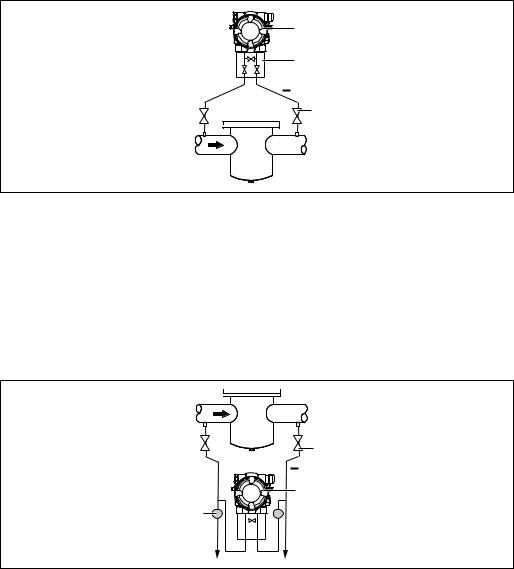
Level measurement in a closed container with superimposed steam
max.
min.
–
+
 1
1
 2
2
3
6

 4 5
4 5


–
A0029791
Measuring layout for level measurement in a container with superimposed steam
1Condensate trap
2Shut-off valves
3Deltabar M
4Three-valve manifold
5Separator
6Drain valves
•Mount the Deltabar M below the lower measuring connection so that the impulse piping is always filled with liquid.
•Always connect the low-pressure side above the maximum level.
•A condensate trap ensures constant pressure on the low-pressure side.
28 |
Endress+Hauser |
Cerabar M, Deltabar M, Deltapilot M |
Installation |
|
|
•When measuring in media with solid parts, such as dirty liquids, installing separators and drain valves is useful for capturing and removing sediment.
Installation position for differential pressure measurement
Differential pressure measurement in gases and steam
1
2
+
3
4
A0029792
Measuring layout for differential pressure measurement in gases and steam
1Deltabar M
2Three-valve manifold
3Shut-off valves
4e.g. filter
•Mount the Deltabar M above the measuring point so that the condensate which may be present, can run off into the process piping.
Differential pressure measurement in liquids
1
2
+
3
6

 4 5
4 5


A0029798
Measuring layout for differential pressure measurement in liquids
1e.g. filter
2Shut-off valves
3Deltabar M
4Three-valve manifold
5Separator
6Drain valves
•Mount the Deltabar M below the measuring point so that the impulse piping is always filled with liquid and gas bubbles can run back into the process piping.
•When measuring in media with solid parts, such as dirty liquids, installing separators and drain valves is useful for capturing and removing sediment.
Endress+Hauser |
29 |

Installation |
Cerabar M, Deltabar M, Deltapilot M |
|
|
4.6.2Wall and pipe-mounting (option)
Endress+Hauser offers the following mounting brackets for installing the device on pipes or walls:
Standard design |
Heavy duty design |
|
|
A0031326 |
A0031327 |
When using a valve block, the block's dimensions must be taken into account.
Bracket for wall and pipe mounting including retaining bracket for pipe mounting and two nuts.
material of the screws used to secure the device depend on the order code.
Technical data (e.g. dimensions or order numbers for screws) see accessory document SD01553P/00/EN.
Please note the following when mounting:
•To prevent the mounting screws from scoring, lubricate them with a multi-purpose grease prior to mounting.
•In the case of pipe mounting, the nuts on the bracket must be tightened uniformly with a torque of at least 30 Nm (22.13 lbf ft).
•For installation purposes, only use the screws with item number (2) (see the following diagram).
30 |
Endress+Hauser |
Loading...