


 Loading...
BA01270P/00/EN/07.18
71404632
Products |
Solutions |
Services |
|
|
|
Operating Instructions
Ceraphant PTC31B, PTP31B,
PTP33B
Process pressure measurement
Pressure switch for safe measurement and monitoring of absolute and gauge pressure

Ceraphant PTC31B, PTP31B, PTP33B
|
|
|
|
|
|
|
|
|
|
|
|
|
|
|
|
|
|
|
|
|
|
|
|
|
|
|
|
|
|
|
|
|
|
|
|
|
|
|
|
|
|
|
|
|
ORDER CODE: |
|
|
|
|
|
|
|
|
|
|
|
|
|
|
|
|
|
|
|
|
XXXXX-XXXXXX |
|
|
|
|
|
|
|
|
|
|
|
|
|
|
|
||
1. |
|
|
SER. NO.: |
|
|
|
|
|
|
|
|
|
|
|
|
|
|
|
|
|
|
XXXXXXXXXXXX |
|
|
|
|
|
|
|
|
|
|
|
|
|
|
|
||||
|
|
|
EXT. ORD. CD.: |
|
|
|
|
|
|
|
|
|
|
|
|
|
|
|
|
|
|
|
|
XXX.XXXX.XX |
|
|
|
|
|
|
|
|
|
|
|
|
|
|
|
||
|
|
|
|
|
|
|
|
|
|
|
|
|
|
|
|
|
|
|
|
|
|
|
|
|
|
|
|
|
|
|
|
|
|
|
|
|
|
|
|
|
|
|
|
|
|
|
|
|
|
|
|
|
|
|
|
|
|
|
|
|
|
|
|
|
|
|
|
|
|
|
|
|
|
|
|
|
|
|
|
|
|
|
|
|
|
|
|
|
|
|
|
|
|
|
|
|
|
|
|
|
|
|
|
|
|
|
|
|
|
|
|
|
|
|
|
|
|
|
|
|
|
|
|
|
|
|
|
|
|
|
|
|
|
|
|
|
|
|
|
|
|
|
|
|
|
|
|
|
|
Serial number |
|
|
|
|
|
|
|
|
|
|
|
|
|
|
|
|
|
|||||
|
|
|
|
|
|
|
|
|
|
|
|
|
2. |
www.endress.com/deviceviewer |
|
|
|
|
|
Endress+Hauser |
|||||
|
|
|
|
|
|
|
|
|
|
|
Operations App |
|
|
|
|
|
|
|
|
|
|
|
|
|
|
|
|
|
|
|
|
|
|
|
|
|
|
|
|
|
|
|
|
|
|
|
|
|
|
|
|
|
|
|
|
|
|
|
|
|
|
|
|
|
|
|
|
|
|
|
|
|
|
|
|
|
|
|
|
|
|
|
|
|
|
|
|
|
|
|
3.
A0023555
•Make sure the document is stored in a safe place such that it is always available when working on or with the device.
•To avoid danger to individuals or the facility, read the "Basic safety instructions" section carefully, as well as all other safety instructions in the document that are specific to working procedures.
•The manufacturer reserves the right to modify technical data without prior notice. Your Endress+Hauser distributor will supply you with current information and updates to these Instructions.
2 |
Endress+Hauser |

Ceraphant PTC31B, PTP31B, PTP33B |
Table of contents |
|
|
Table of contents
1 |
Document information . . . . . . . . . . . . . . |
5 |
1.1 |
Document function . . . . . . . . . . . . . . . . . . . . . |
5 |
1.2 |
Symbols used . . . . . . . . . . . . . . . . . . . . . . . . . . |
5 |
1.3 |
Documentation . . . . . . . . . . . . . . . . . . . . . . . . |
6 |
1.4 |
Terms and abbreviations . . . . . . . . . . . . . . . . . |
7 |
1.5 |
Turn down calculation . . . . . . . . . . . . . . . . . . . |
8 |
2 |
Basic safety instructions . . . . . . . . . . . . |
9 |
2.1 |
Requirements concerning the staff . . . . . . . . . . |
9 |
2.2 |
Designated use . . . . . . . . . . . . . . . . . . . . . . . . |
9 |
2.3 |
Workplace safety . . . . . . . . . . . . . . . . . . . . . . |
10 |
2.4 |
Operational safety . . . . . . . . . . . . . . . . . . . . . |
10 |
2.5 |
Product safety . . . . . . . . . . . . . . . . . . . . . . . . |
10 |
3 |
Product description . . . . . . . . . . . . . . . . |
11 |
3.1 |
Product design . . . . . . . . . . . . . . . . . . . . . . . . |
11 |
3.2 |
Function . . . . . . . . . . . . . . . . . . . . . . . . . . . . |
11 |
4Incoming acceptance and product
|
identification . . . . . . . . . . . . . . . . . . . . . |
13 |
4.1 |
Incoming acceptance . . . . . . . . . . . . . . . . . . . |
13 |
4.2 |
Product identification . . . . . . . . . . . . . . . . . . . |
14 |
4.3 |
Storage and transport . . . . . . . . . . . . . . . . . . |
15 |
5 |
Installation . . . . . . . . . . . . . . . . . . . . . . . |
16 |
5.1 |
Mounting dimensions . . . . . . . . . . . . . . . . . . |
16 |
5.2 |
Installation conditions . . . . . . . . . . . . . . . . . . |
16 |
5.3 |
Influence of the installation position . . . . . . . . |
16 |
5.4 |
Mounting location . . . . . . . . . . . . . . . . . . . . . |
17 |
5.5Mounting instructions for oxygen
applications . . . . . . . . . . . . . . . . . . . . . . . . . . 19 5.6 Post-installation check . . . . . . . . . . . . . . . . . . 19
6 |
Electrical connection . . . . . . . . . . . . . . |
20 |
6.1 |
Connecting the measuring unit . . . . . . . . . . . . |
20 |
6.2 |
Switching capacity . . . . . . . . . . . . . . . . . . . . . |
21 |
6.3 |
Connection conditions . . . . . . . . . . . . . . . . . . |
22 |
6.4 |
Connection data . . . . . . . . . . . . . . . . . . . . . . . |
22 |
6.5 |
Post-connection check . . . . . . . . . . . . . . . . . . |
22 |
7 |
Operation options . . . . . . . . . . . . . . . . . |
23 |
7.1 |
Operation with an operating menu . . . . . . . . . |
23 |
7.2 |
Structure of the operating menu . . . . . . . . . . . |
23 |
7.3 |
Operation with local display . . . . . . . . . . . . . . |
23 |
7.4General value adjustment and rejection of
|
illegal entries . . . . . . . . . . . . . . . . . . . . . . . . . |
24 |
7.5 |
Navigation and selection from list . . . . . . . . . |
24 |
7.6 |
Locking and unlocking operation . . . . . . . . . . |
25 |
7.7 |
Navigation examples . . . . . . . . . . . . . . . . . . . |
27 |
7.8 |
Status LEDs . . . . . . . . . . . . . . . . . . . . . . . . . . |
27 |
7.9 |
Resetting to factory settings (reset) . . . . . . . . |
27 |
Endress+Hauser |
|
|
8 |
Commissioning . . . . . . . . . . . . . . . . . . . . |
28 |
8.1 Function check . . . . . . . . . . . . . . . . . . . . . . . 28 8.2 Enabling configuration/operation . . . . . . . . . . 28 8.3 Commissioning with an operating menu . . . . . 28
8.4Configuring pressure measurement (only for
|
devices with a current output) . . . . . . . . . . . . |
28 |
8.5 |
Performing position adjustment . . . . . . . . . . . |
30 |
8.6 |
Configuring process monitoring . . . . . . . . . . . |
33 |
8.7 |
Functions of switch output . . . . . . . . . . . . . . . |
33 |
8.8 |
Current output . . . . . . . . . . . . . . . . . . . . . . . . |
36 |
8.9 |
Application examples . . . . . . . . . . . . . . . . . . . |
38 |
8.10 |
Configuring the local display . . . . . . . . . . . . . |
38 |
8.11Protecting settings from unauthorized
access . . . . . . . . . . . . . . . . . . . . . . . . . . . . . . 39
9 |
Diagnostics and troubleshooting . . . |
40 |
9.1 |
Troubleshooting . . . . . . . . . . . . . . . . . . . . . . |
40 |
9.2 |
Diagnostic events . . . . . . . . . . . . . . . . . . . . . . |
41 |
9.3Behavior of the device in the event of a
fault . . . . . . . . . . . . . . . . . . . . . . . . . . . . . . . |
43 |
9.4 Response of output to errors . . . . . . . . . . . . . . |
43 |
9.5Behavior of the device in the event of a
voltage drop . . . . . . . . . . . . . . . . . . . . . . . . . 44
9.6Behavior of the device in the event of an
incorrect entry . . . . . . . . . . . . . . . . . . . . . . . |
44 |
9.7 Disposal . . . . . . . . . . . . . . . . . . . . . . . . . . . . |
45 |
10 Maintenance . . . . . . . . . . . . . . . . . . . . . . 45
10.1 Exterior cleaning . . . . . . . . . . . . . . . . . . . . . . 45
11 Repairs . . . . . . . . . . . . . . . . . . . . . . . . . . . 46
11.1 General notes . . . . . . . . . . . . . . . . . . . . . . . . 46 11.2 Return . . . . . . . . . . . . . . . . . . . . . . . . . . . . . . 46 11.3 Disposal . . . . . . . . . . . . . . . . . . . . . . . . . . . . 46
12 Overview of the operating menu . . . . 47
13 Description of device parameters . . . 49
13.1 Switch output 1 and switch output 2 . . . . . . . . 49 13.2 Current output . . . . . . . . . . . . . . . . . . . . . . . . 53 13.3 EF menu (extended functions) . . . . . . . . . . . . 54 13.4 DIAG menu (diagnosis) . . . . . . . . . . . . . . . . . 64
14 Accessories . . . . . . . . . . . . . . . . . . . . . . . 66
14.1 Weld-in adapter . . . . . . . . . . . . . . . . . . . . . . 66 14.2 Process adapter M24 . . . . . . . . . . . . . . . . . . . 66 14.3 M12 plug connectors . . . . . . . . . . . . . . . . . . . 67
15 Technical data . . . . . . . . . . . . . . . . . . . . 68
15.1 Input . . . . . . . . . . . . . . . . . . . . . . . . . . . . . . . 68 15.2 Output . . . . . . . . . . . . . . . . . . . . . . . . . . . . . 71
3
Table of contents |
Ceraphant PTC31B, PTP31B, PTP33B |
|
|
15.3Performance characteristics of ceramic
process isolating diaphragm . . . . . . . . . . . . . . 74
15.4Performance characteristics of metal process
isolating diaphragm . . . . . . . . . . . . . . . . . . . . 76 15.5 Environment . . . . . . . . . . . . . . . . . . . . . . . . . 78 15.6 Process . . . . . . . . . . . . . . . . . . . . . . . . . . . . . 80
Index . . . . . . . . . . . . . . . . . . . . . . . . . . . . . . . . . . 82
4 |
Endress+Hauser |

Ceraphant PTC31B, PTP31B, PTP33B |
Document information |
|
|
1Document information
1.1Document function
These Operating Instructions contain all the information that is required in various phases of the life cycle of the device: from product identification, incoming acceptance and storage, to mounting, connection, operation and commissioning through to troubleshooting, maintenance and disposal.
1.2Symbols used
1.2.1Safety symbols
Symbol Meaning
DANGER!
 DANGER This symbol alerts you to a dangerous situation. Failure to avoid this situation will result in serious or fatal injury.
WARNING!
 WARNING This symbol alerts you to a dangerous situation. Failure to avoid this situation can result in serious or fatal injury.
CAUTION!
 CAUTION This symbol alerts you to a dangerous situation. Failure to avoid this situation can result in minor or medium injury.
NOTICE!
NOTICE This symbol contains information on procedures and other facts which do not result in personal injury.
1.2.2Electrical symbols
Symbol |
Meaning |
Symbol |
Meaning |
|
|
|
|
|
Protective ground connection |
|
Ground connection |
|
A terminal which must be connected |
|
A grounded terminal which, as far as |
|
to ground prior to establishing any |
|
the operator is concerned, is |
|
other connections. |
|
grounded via a grounding system. |
|
|
|
|
1.2.3 |
Tool symbols |
Symbol |
Meaning |
|
Open-ended wrench |
A0011222
1.2.4Symbols for certain types of information
Symbol Meaning
Permitted
Procedures, processes or actions that are permitted.
Forbidden
Procedures, processes or actions that are forbidden.
Tip
Indicates additional information.
Endress+Hauser |
5 |

Document information |
Ceraphant PTC31B, PTP31B, PTP33B |
Symbol |
Meaning |
|
Reference to documentation |
A |
Reference to page |
Reference to graphic
1. , 2. , 3. … Series of steps
Result of a step
Visual inspection
1.2.5Symbols in graphics
|
Symbol |
Meaning |
|||||
|
|
|
|
|
|
|
|
1, 2, 3 ... |
Item numbers |
||||||
|
|
|
|
|
|
|
|
|
|
|
|
|
|
|
Series of steps |
|
1. |
, |
2. |
, |
3. |
… |
|
|
|
||||||
A, B, C, ... |
Views |
||||||
|
|
|
|
|
|
|
|
1.3Documentation
The document types listed are available:
In the Download Area of the Endress+Hauser Internet site: www.endress.com →
Download
1.3.1Technical Information (TI): planning aid for your device
PTC31B: TI01130P
PTP31B: TI01130P
PTP33B: TI01246P
The document contains all the technical data on the device and provides an overview of the accessories and other products that can be ordered for the device.
1.3.2Brief Operating Instructions (KA): getting the 1st measured value quickly
KA01163P:
These instructions contain all the essential information from incoming acceptance to initial commissioning.
6 |
Endress+Hauser |

Ceraphant PTC31B, PTP31B, PTP33B |
Document information |
|
|
1.4Terms and abbreviations
|
|
|
1 |
|
|
|
|
|
2 |
|
|
|
|
3 |
|
|
|
|
|
4 |
|
|
|
|
|
|
|
|
P |
|
0 |
|
|
|
|
LRL |
LRV |
URV |
URL |
MWP |
OPL |
A0029505
Item |
Term/ |
Explanation |
|
abbreviation |
|
|
|
|
1 |
OPL |
The OPL (over pressure limit = sensor overload limit) for the measuring device |
|
|
depends on the lowest-rated element, with regard to pressure, of the selected |
|
|
components, i.e. the process connection has to be taken into consideration in |
|
|
addition to the measuring cell. Also observe pressure-temperature dependency. For |
|
|
the relevant standards and additional notes, see the "Pressure specifications" section |
|
|
→ 81 . |
|
|
The OPL may only be applied for a limited period of time. |
|
|
|
2 |
MWP |
The MWP (maximum working pressure) for the sensors depends on the lowest- |
|
|
rated element, with regard to pressure, of the selected components, i.e. the process |
|
|
connection has to be taken into consideration in addition to the measuring cell. |
|
|
Also observe pressure-temperature dependency. For the relevant standards and |
|
|
additional notes, see the "Pressure specifications" section → 81 . |
|
|
The MWP may be applied at the device for an unlimited period. |
|
|
The MWP can also be found on the nameplate. |
|
|
|
3 |
Maximum sensor |
Span between LRL and URL |
|
measuring range |
This sensor measuring range is equivalent to the maximum calibratable/adjustable |
|
|
span. |
|
|
|
4 |
Calibrated/adjusted |
Span between LRV and URV |
|
span |
Factory setting: 0 to URL |
|
|
Other calibrated spans can be ordered as customized spans. |
|
|
|
p |
- |
Pressure |
|
|
|
- |
LRL |
Lower range limit |
|
|
|
- |
URL |
Upper range limit |
|
|
|
- |
LRV |
Lower range value |
|
|
|
- |
URV |
Upper range value |
|
|
|
- |
TD (turn down) |
Turn down |
|
|
Example - see the following section. |
|
|
|
Endress+Hauser |
7 |

Document information |
Ceraphant PTC31B, PTP31B, PTP33B |
|
|
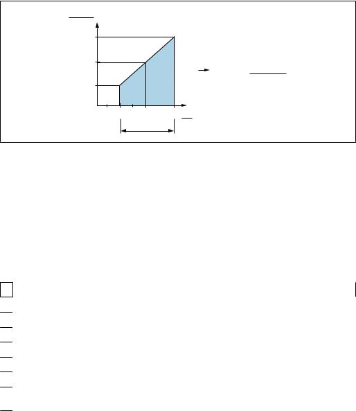
1.5Turn down calculation
|
|
|
1 = 2 |
|
3 |
|
LRL LRV |
URV |
URL |
||||
|
|
|
|
|
|
|
|
|
|
|
|
|
|
|
|
|
|
|
|
|
|
|
|
|
|
|
|
A0029545
1 |
Calibrated/adjusted span |
|
|
|
|||
2 |
Zero point-based span |
|
|
|
|
||
3 |
URL sensor |
|
|
|
|
||
|
|
|
|
|
|
||
Example |
|
|
|
|
|||
|
|
|
|
|
|
||
• Sensor:10 bar (150 psi) |
|
|
|
• Calibrated/adjusted span: 0 to 5 bar (0 to 75 psi) |
|||
• Upper range value (URL) = 10 bar (150 psi) |
• Lower range value (LRV) = 0 bar (0 psi) |
||||||
Turn down (TD): |
|
|
|
• Upper range value (URV) = 5 bar (75 psi) |
|||
|
|
|
|
||||
|
TD |
= |
|
URL |
|
|
|
|
|
|
|
|
|
||
|
|URV |
- |
LRV| |
|
|||
|
|
|
|
||||
|
|
|
10 bar (150 psi) |
|
|||
|
TD |
= |
|
|
|
= |
2 |
|
|5 bar (75 psi) |
- |
|
||||
|
|
|
0 bar (0 psi)| |
|
|||
In this example, the TD is 2:1.
This span is based on the zero point.
8 |
Endress+Hauser |
Ceraphant PTC31B, PTP31B, PTP33B |
Basic safety instructions |
|
|
2Basic safety instructions
2.1Requirements concerning the staff
The personnel for installation, commissioning, diagnostics and maintenance must fulfill the following requirements:
Trained, qualified specialists: must have a relevant qualification for this specific function and task
Are authorized by the plant owner/operator
Are familiar with federal/national regulations
Before beginning work, the specialist staff must have read and understood the instructions in the Operating Instructions and supplementary documentation as well as in the certificates (depending on the application)
Following instructions and basic conditions
The operating personnel must fulfill the following requirements:
Being instructed and authorized according to the requirements of the task by the facility's owner-operator
Following the instructions in these Operating Instructions
2.2Designated use
2.2.1Application and media
The Ceraphant is a pressure switch for measuring and monitoring absolute and gauge pressure in industrial systems. The process-wetted materials of the measuring device must have an adequate level of resistance to the media.
The measuring device may be used for the following measurements (process variables)
•in compliance with the limit values specified under "Technical data"
•in compliance with the conditions that are listed in this manual.
Measured process variable
Gauge pressure or absolute pressure
Calculated process variable
Pressure
2.2.2Incorrect use
The manufacturer is not liable for damage caused by improper or non-designated use.
Verification for borderline cases:
For special fluids and fluids for cleaning, Endress+Hauser is glad to provide assistance in verifying the corrosion resistance of process-wetted materials, but does not accept any warranty or liability.
2.2.3Residual risks
When in operation, the housing may reach a temperature close to the process temperature.
Danger of burns from contact with surfaces!
For elevated process temperatures, ensure protection against contact to prevent burns.
Endress+Hauser |
9 |
Basic safety instructions |
Ceraphant PTC31B, PTP31B, PTP33B |
|
|
2.3Workplace safety
For work on and with the device:
Wear the required personal protective equipment according to federal/national regulations.
Switch off the supply voltage before connecting the device.
2.4Operational safety
Risk of injury!
Operate the device in proper technical condition and fail-safe condition only.
The operator is responsible for interference-free operation of the device.
Conversions to the device
Unauthorized modifications to the device are not permitted and can lead to unforeseeable dangers.
If, despite this, modifications are required, consult with Endress+Hauser.
Hazardous area
To eliminate the risk of danger to persons or the facility when the device is used in the approval-related area (e.g. pressure equipment safety):
Check the nameplate to verify if the device ordered can be put to its intended use in the approval-related area.
2.5Product safety
This measuring device is designed in accordance with good engineering practice to meet state-of-the-art safety requirements, has been tested, and left the factory in a condition in which it is safe to operate.
It meets general safety standards and legal requirements. It also complies with the EU directives listed in the device-specific EU Declaration of Conformity. Endress+Hauser confirms this by affixing the CE mark to the device.
10 |
Endress+Hauser |
Ceraphant PTC31B, PTP31B, PTP33B |
Product description |
|
|
3Product description
3.1Product design
|
|
|
|
|
Overview |
|
|
Position |
Description |
A |
B |
C |
A |
Valve plug |
|
|
|||
|
|
|
B |
Cable |
|
|
|
C |
M12 plug |
|
|
|
|
Housing cap made of plastic |
|
|
|
A0022015 |
|
|
D |
|
D |
Housing |
|
|
|
E |
Process connection (sample illustration) |
|
E |
|
|
|
|
|
|
A0027226 |
|
|
D |
|
|
|
|
E |
|
|
|
|
|
|
A0027215 |
|
|
D |
|
|
|
|
E |
|
|
|
|
|
|
A0027227 |
|
|
3.2 |
Function |
|
|
3.2.1Calculating the pressure
Devices with ceramic process isolating diaphragm (Ceraphire®)
The ceramic sensor is an oil-free sensor, i.e. the process pressure acts directly on the robust ceramic process isolating diaphragm and causes it to deflect. A pressure-dependent
Endress+Hauser |
11 |
Product description |
Ceraphant PTC31B, PTP31B, PTP33B |
|
|
change in capacitance is measured at the electrodes of the ceramic substrate and the process isolating diaphragm. The measuring range is determined by the thickness of the ceramic process isolating diaphragm.
Devices with metallic process isolating diaphragm
The process pressure deflects the metal process isolating diaphragm of the sensor and a fill fluid transfers the pressure to a Wheatstone bridge (semiconductor technology). The pressure-dependent change in the bridge output voltage is measured and evaluated.
12 |
Endress+Hauser |

Ceraphant PTC31B, PTP31B, PTP33B |
Incoming acceptance and product identification |
|
|
4Incoming acceptance and product identification
4.1Incoming acceptance
A0028673
A0028673
A0028673
DELIVERY NOTE

 1 = 2
1 = 2 
A0016870
Is the order code on the delivery note (1) identical to the order code on the product sticker (2)?
A0022099
E |
E |
A0022101
Are the goods undamaged?
DELIVERY NOTE |
E |
|
A0022104
Do the data on the nameplate correspond to the order specifications and the delivery note?
Endress+Hauser |
13 |

Incoming acceptance and product identification |
Ceraphant PTC31B, PTP31B, PTP33B |
|
|
A0028673
A0022106
Is the documentation available?
If required (see nameplate): Are the safety instructions (XA) provided?
If one of these conditions does not apply, please contact your
Endress+Hauser sales office.
4.2Product identification
The following options are available for the identification of the measuring device:
•Nameplate specifications
•Order code with a breakdown of the device features on the delivery note
•Enter the serial numbers from the nameplates in W@M Device Viewer (www.endress.com/deviceviewer): All the information about the measuring device is displayed.
For an overview of the technical documentation provided, enter the serial number from the nameplates in W@M Device Viewer (www.endress.com/deviceviewer)
4.2.1Manufacturer address
Endress+Hauser SE+Co. KG Hauptstraße 1
79689 Maulburg, Germany
Address of the manufacturing plant: See nameplate.
4.2.2Nameplate
1
2 Ceraphant
3
4
5
Made in Germany,
D-79689 Maulburg
Ord. cd.:
 Ser. no.:
  Ext. ord. cd.:
Date:
TAG:
A0030101
1 Manufacturer's address
2 Device name
3 Order number
4Serial number
5Extended order number
14 |
Endress+Hauser |

Ceraphant PTC31B, PTP31B, PTP33B |
Incoming acceptance and product identification |
|
|
4.3Storage and transport
4.3.1Storage conditions
Use original packaging.
Store the measuring device in clean and dry conditions and protect from damage caused by shocks (EN 837-2).
Storage temperature range
–40 to +85 °C (–40 to +185 °F)
4.3.2Transporting the product to the measuring point
LWARNING
Incorrect transport!
Housing and diaphragm may become damaged, and there is a risk of injury!
Transport the measuring device to the measuring point in its original packaging or by the process connection.
Endress+Hauser |
15 |

Installation |
Ceraphant PTC31B, PTP31B, PTP33B |
|
|
5Installation
5.1Mounting dimensions
For dimensions, see the "Mechanical construction" section in the Technical Information.
5.2Installation conditions
•Moisture must not penetrate the housing when mounting the device, establishing the electrical connection and during operation.
•Do not clean or touch process isolating diaphragms with hard and/or pointed objects.
•Do not remove process isolating diaphragm protection until shortly before installation.
•Always tighten the cable entry firmly.
•Point the cable and connector downwards where possible to prevent moisture from entering (e.g. rain or condensation water).
•Protect housing against impact.
•For devices with gauge pressure sensor and M12 or valve plug, the following applies:
NOTICE
If a heated device is cooled in the course of a cleaning process (by cold water, for example), a vacuum develops for a short time causing moisture to penetrate the sensor via the pressure compensation element (1).
Device could be destroyed!
In the event of this happening, mount the device in such a way that the pressure compensation element (1) is pointing downwards at an angle or to the side, if possible.
|
|
1 |
1 |
1 |
1 |
A0022252
5.3Influence of the installation position
Any orientation is possible. However, the orientation may cause a zero point shift i.e. the measured value does not show zero when the vessel is empty or partially full.
A |
B |
C |
A0024708
16 |
Endress+Hauser |
Ceraphant PTC31B, PTP31B, PTP33B |
|
|
Installation |
|
|
|
|
|
|
|
|
|
|
|
|
Type |
Process isolating |
Process isolating diaphragm |
Process isolating diaphragm |
|
|
diaphragm axis is |
pointing upwards (B) |
pointing downwards (C) |
|
|
horizontal (A) |
|
|
|
|
|
|
|
|
PTP31B |
Calibration position, no |
Up to +4 mbar (+0.058 psi) |
Up to –4 mbar (–0.058 psi) |
|
PTP33B |
effect |
|
|
|
|
|
|
|
|
PTC31B |
Calibration position, no |
Up to |
Up to |
|
< 1 bar (15 psi) |
effect |
+0.3 mbar (+0.0044 psi) |
–0.3 mbar (–0.0044 psi) |
|
|
|
|
|
|
PTC31B |
Calibration position, no |
Up to +3 mbar (+0.0435 psi) |
Up to –3 mbar (–0.0435 psi) |
|
≥1 bar (15 psi) |
effect |
|
|
|
|
|
|
|
 A position-dependent zero shift can be corrected on the device .
5.4Mounting location
5.4.1Pressure measurement
Pressure measurement in gases
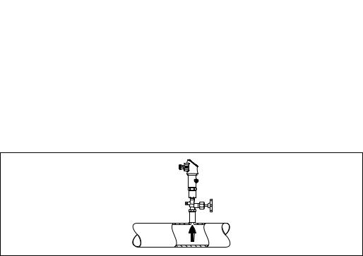
Mount the device with shutoff device above the tapping point so that any condensate can flow into the process.
1
2
A0025920
1Device
2Shutoff device
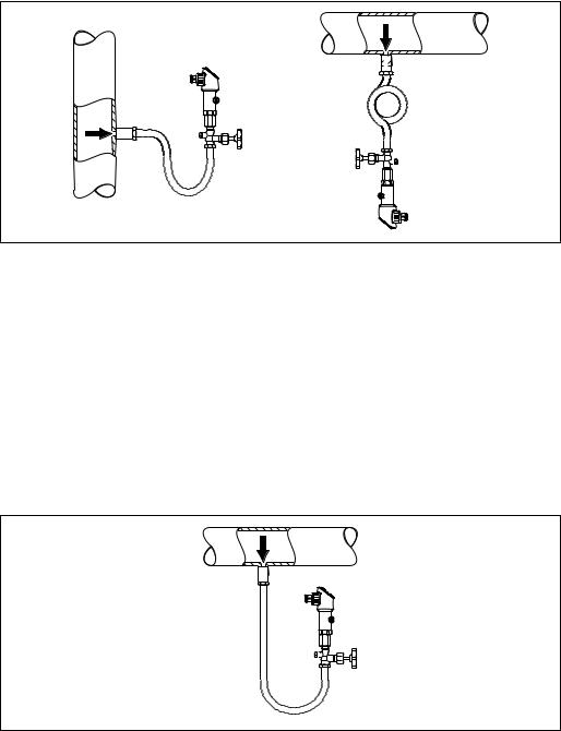
Pressure measurement in vapors
For pressure measurement in vapors, use a siphon. The siphon reduces the temperature to almost ambient temperature. Preferably mount the device with the shutoff device and siphon below the tapping point.
Advantage:
•defined water column causes only minor/negligible measuring errors and
•only minor/negligible heat effects on the device.
Mounting above the tapping point is also permitted.
Note the max. permitted ambient temperature of the transmitter!
Take the influence of the hydrostatic water column into consideration.
Endress+Hauser |
17 |
Installation |
Ceraphant PTC31B, PTP31B, PTP33B |
||
|
|
|
|
|
|
|
|
|
|
|
|
1
4
2
2
3
1
A0025921
1Device
2Shutoff device
3 Siphon
4Siphon
Pressure measurement in liquids
Mount the device with a shutoff device and siphon below or at the same height as the tapping point.
Advantage:
•defined water column causes only minor/negligible measuring errors and
•air bubbles can be released to the process.
Take the influence of the hydrostatic water column into consideration.
1
2
3
A0025922
1Device
2 Shutoff device
3Siphon
5.4.2Level measurement
•Always install the device below the lowest measuring point.
•Do not install the device at the following positions:
–In the filling curtain
–In the tank outlet
–in the suction area of a pump
–Or at a point in the tank which could be affected by pressure pulses from the agitator.
•A functional test can be carried out more easily if you mount the device downstream from a shutoff device.
18 |
Endress+Hauser |

Ceraphant PTC31B, PTP31B, PTP33B |
Installation |
|
A0025923 |
5.5Mounting instructions for oxygen applications
Oxygen and other gases can react explosively to oils, grease and plastics, such that, among other things, the following precautions must be taken:
• All components of the system, such as measuring devices, must be cleaned in accordance with the BAM requirements.
• Dependent on the materials used, a certain maximum temperature and a maximum pressure for oxygen applications must not be exceeded.
• The following table lists devices (devices only, not accessories or enclosed accessories), which are suitable for gaseous oxygen applications.
Device |
pmax for oxygen applications |
Tmax for oxygen applications |
Option 1) |
|
PTC31B |
40 bar (600 psi) |
–10 to +60 °C (+14 to +140 °F) |
HB |
|
|
|
|
|
|
1) |
Product Configurator, order code for "Service" |
|
|
|
5.6Post-installation check
Is the device undamaged (visual inspection)?
Does the device comply with the measuring point specifications? For example:
• Process temperature
•Process pressure
•Ambient temperature range
•Measuring range
Are the measuring point identification and labeling correct (visual inspection)?
Is the device adequately protected against precipitation and direct sunlight?
Are the securing screws tightened securely?
Is the pressure compensation element pointing downwards at an angle or to the side?
To prevent moisture from penetrating, ensure that the connecting cables/plugs are pointing downwards.
Endress+Hauser |
19 |

Electrical connection |
Ceraphant PTC31B, PTP31B, PTP33B |
|
|
6Electrical connection
6.1Connecting the measuring unit
6.1.1Terminal assignment
LWARNING
Risk of injury from the uncontrolled activation of processes!
Switch off the supply voltage before connecting the device.
Make sure that downstream processes are not started unintentionally.
LWARNING
Limitation of electrical safety due to incorrect connection!
In accordance with IEC/EN61010 a separate circuit breaker must be provided for the device .
The device must be operated with a 630 mA fine-wire fuse (slow-blow).
Protective circuits against reverse polarity are integrated.
NOTICE
Damage to analog input of PLC resulting from incorrect connection
Do not connect the active PNP switch output of the device to the 4 to 20 mA input of a PLC.
Connect the device in the following order:
1.Check that the supply voltage corresponds to the supply voltage indicated on the nameplate.
2.Connect the device in accordance with the following diagram.
Switch on the supply voltage.
For devices with a cable connection: do not close reference air hose (see (a) in the following drawings)! Protect reference air hose against penetration by water/condensate.
1 x PNP switch output R1 |
|
|
|
|
|
|
||
M12 plug |
|
Valve plug |
|
Cable |
|
|
||
|
|
0.63A |
|
0.63A |
|
1 |
0.63A |
|
|
|
L+ |
1 |
|
L+ |
|
L+ |
|
|
1 |
|
|
|
||||
2 |
|
3 |
|
|
2a |
|
|
|
|
|
|
|
" |
|
|
|
|
3 |
4 |
R1 |
|
4 |
3 |
R1 |
|
|
|
R1 |
|
|
|||||
|
|
L– |
|
|
|
L– |
||
|
|
2 |
|
|
4 |
|
||
|
|
A0029268 |
|
L– |
|
" |
||
|
|
|
|
|
||||
|
|
|
|
|
A0023271 |
2b |
|
|
|
|
|
|
|
|
|
(a) |
|
|
|
|
|
|
|
|
|
|
|
|
|
|
|
|
|
|
A0022801 |
|
|
|
|
|
1 |
brown = L+ |
|
|
|
|
|
|
|
2a black = switch output 1 |
|||
|
|
|
|
|
2b |
white = not in use |
|
|
|
|
|
|
|
3 |
blue = L- |
|
|
|
|
|
|
|
4 |
green/yellow = ground |
||
|
|
|
|
|
(a) |
reference air hose |
|
|
20 |
Endress+Hauser |
Ceraphant PTC31B, PTP31B, PTP33B |
Electrical connection |
|
|
2 x PNP switch output R1 and R2 |
|
M12 plug |
|
Valve plug |
Cable |
|
|
||
|
|
0.63A |
- |
|
1 |
0.63A |
L+ |
|
|
|
L+ |
|
|
||
|
|
|
|
2a |
|
||
2 |
1 |
|
|
|
|
|
|
|
|
|
2b |
|
|
||
3 |
4 |
R1 |
|
|
|
R1 |
|
|
|
|
R2 |
||||
|
|
|
|
||||
|
|
|
L– |
|
3 |
|
|
|
|
|
|
|
L– |
||
|
|
|
|
|
|
||
|
|
R2 |
|
|
4 |
|
|
|
|
|
|
|
" |
||
|
|
|
|
|
|
||
|
|
|
|
|
|
|
|
|
|
|
A0023248 |
|
|
|
(a) |
|
|
|
|
|
|
|
A0023282 |
|
|
|
|
1 |
brown = L+ |
|
|
|
|
|
|
2a black = switch output 1 |
|||
|
|
|
|
2b |
white = switch output 2 |
||
|
|
|
|
3 |
blue = L- |
|
|
|
|
|
|
4 |
green/yellow = ground |
||
|
|
|
|
(a) |
reference air hose |
|
|
1 x PNP switch output R1 with additional analog output 4 to 20 mA (active)
M12 plug |
|
|
|
|
|
|
Valve plug |
Cable |
|
|
|
|
|
|
|
|
||||||
|
|
|
|
|
|
|
|
|
|
|
|
|
|
|
|
|
|
|
|
|
|
|
|
|
|
|
|
0.63A |
|
- |
|
1 |
0.63A |
L+ |
|||||||||||
|
|
|
|
|
|
|
|
|
|
L+ |
|
|
|
|
|
|
|
|
|
|||
2 |
|
1 |
|
|
|
|
|
|
|
|
|
2a |
|
|
|
|
|
|
|
|
||
|
|
|
|
|
|
|
|
|
|
|
|
|
|
|
|
|
||||||
|
|
|
|
|
|
|
|
|
|
2b |
|
|
|
|
|
|
|
|
||||
|
|
|
|
|
|
|
|
R1 |
|
|
|
|
|
|
|
|
|
|
|
|
||
|
3 |
4 |
|
|
|
L– |
|
|
|
|
|
|
|
|
|
R1 |
||||||
|
|
|
|
|
|
|
|
|
|
|
|
|
3 |
|
|
|
|
|
L– |
|||
|
|
|
|
|
|
|
|
|
|
|
|
|
|
|
|
|||||||
|
|
|
|
|
|
|
|
|
|
|
|
|
|
|
|
|
|
|||||
|
|
|
|
|
|
|
|
|
|
|
|
|
|
|
|
|
|
|||||
|
|
|
|
|
|
|
|
|
|
|
|
|
4 |
|
|
|
|
|
" |
|||
|
|
|
|
|
|
|
|
|
|
|
|
|
|
|
|
|
|
|
|
|||
|
|
|
|
|
|
|
|
|
|
A0023249 |
|
|
|
|
|
|
|
|
|
(a) |
||
|
|
|
|
|
|
|
|
|
|
|
|
|
|
|
|
|
|
|
|
|
|
|
|
|
|
|
|
|
|
|
|
|
|
|
|
|
|
|
|
|
|
|
|
|
A0030519 |
|
|
|
|
|
|
|
|
|
|
|
|
1 |
brown = L+ |
|
|
|
||||||
|
|
|
|
|
|
|
|
|
|
|
|
2a black = switch output 1 |
||||||||||
|
|
|
|
|
|
|
|
|
|
|
|
2b |
white = analog output 4 to 20 mA |
|||||||||
|
|
|
|
|
|
|
|
|
|
|
|
3 |
blue = L- |
|
|
|
||||||
|
|
|
|
|
|
|
|
|
|
|
|
4 |
green/yellow = ground |
|||||||||
|
|
|
|
|
|
|
|
|
|
|
|
(a) |
reference air hose |
|
|
|
||||||
|
|
|
|
|
|
|
|
|
|
|
|
|
|
|
|
|
|
|
|
|
|
|
6.1.2Supply voltage
Supply voltage: 10 to 30 V DC
6.1.3Current consumption and alarm signal
Intrinsic power consumption |
Alarm current (for device with analog output) |
|
|
≤ 60 mA |
≥21 mA (factory setting) |
|
|
6.2Switching capacity
•Switch state ON: Ia ≤ 250 mA; switch state OFF: Ia ≤1 mA
•Switch cycles: >10,000,000
•Voltage drop PNP: ≤2 V
•Overload protection: Automatic load testing of switching current;
– Max. capacitive load: 14 μF at max. supply voltage (without resistive load)
– Max. cycle duration: 0.5 s; min. ton: 4 ms
– Periodic disconnection from protective circuit in the event of overcurrent (f = 2 Hz) and "F804" displayed
Endress+Hauser |
21 |
Electrical connection |
Ceraphant PTC31B, PTP31B, PTP33B |
|
|
6.3Connection conditions
6.3.1Cable specification
For valve plug: < 1.5 mm2 (16 AWG) and Ø4.5 to 10 mm (0.18 to 0.39 in)
6.4Connection data
6.4.1Load (for devices with analog output)
The maximum load resistance depends on the terminal voltage and is calculated according to the following formula:
R L MAX |
|
|
|
|
[W] |
|
|
|
|
1022 |
|
|
|
|
587 |
|
|
2 |
|
|
|
|
R L MAX £ |
|
152 |
|
|
|
|
0 |
10 |
20 |
30 UB |
|
|
|
1 |
[V] |
|
|
|
|
|
U B - 6.5V
23MA
A0031107
1Power supply 10 to 30 V DC
2RLmax maximum load resistance
UB Supply voltage
If load is too great:
•Failure current is output and "S803" displayed (output: MIN alarm current)
•Periodic checking to establish if it is possible to quit fault state
6.5Post-connection check
Is the device or cable undamaged (visual check)?
Do the cables comply with the requirements?
Do the mounted cables have adequate strain relief?
Are all the cable glands installed, firmly tightened and leak-tight?
Does the supply voltage match the specifications on the nameplate?
Is the terminal assignment correct ?
If required: has protective ground connection been established?
If supply voltage is present, is the device ready for operation and do values appear on the display module or is the green LED lit on the electronic insert?
22 |
Endress+Hauser |

Ceraphant PTC31B, PTP31B, PTP33B |
Operation options |
|
|
7Operation options
7.1Operation with an operating menu
7.1.1Operating concept
Operation with an operating menu is based on an operation concept with "user roles" .
User role |
Meaning |
|
|
Operator |
Operators are responsible for the devices during normal "operation". This is usually limited to |
(display level) |
reading process values either directly at the device or in a control room. Should an error occur, |
|
these users simply forward the information on the errors but do not intervene themselves. |
|
|
Maintenance |
Service engineers usually work with the devices in the phases following device commissioning. |
(user level) |
They are primarily involved in maintenance and troubleshooting activities for which simple |
|
settings have to be made on the device. Technicians work with the devices over the entire life |
|
cycle of the product. Thus, commissioning and advanced settings and configurations are some |
|
of the tasks they have to carry out. |
|
|
7.2Structure of the operating menu
The menu structure has been implemented according to VDMA 24574-1 and complemented by Endress+Hauser-specific menu items.
User role |
Submenu |
Meaning/use |
|
|
|
Operator (display |
Display/operat. |
Display of measured values, fault and information messages |
level) |
|
|
|
|
|
Maintenance (user |
Parameters on |
Contains all the parameters that are needed to commission |
level) |
the topmost |
measuring operations. A wide range of parameters, which can be |
|
menu level. |
used to configure a typical application, is available at the start. After |
|
|
making settings for all these parameters, the measuring operation |
|
|
should be completely configured in the majority of cases. |
|
|
|
|
EF |
The submenu "EF" (Extended Functions) contains additional |
|
|
parameters which allow more accurate configuration of the |
|
|
measurement, conversion of the measured value and scaling of the |
|
|
output signal. |
|
|
|
|
DIAG |
Contains all the parameters that are needed to detect and analyze |
|
|
operating errors. |
|
|
|
 For an overview of the entire operating menu, see the → 47
7.3Operation with local display
7.3.1Overview
A 1-line liquid crystal display (LCD) is used for display and operation. The local display shows measured values, fault messages and information messages and therefore supports the user through each operating step.
The display is fixed to the housing and can be electronically rotated 180° (see parameter description for "DRO" → 62). This ensures optimum readability of the local display and allows the device to be mounted upside down also.
During measuring operation, the display shows measured values, fault messages and notice messages. In addition, it is possible to switch to menu mode via the operating keys.
Endress+Hauser |
23 |
Operation options |
Ceraphant PTC31B, PTP31B, PTP33B |
|
|
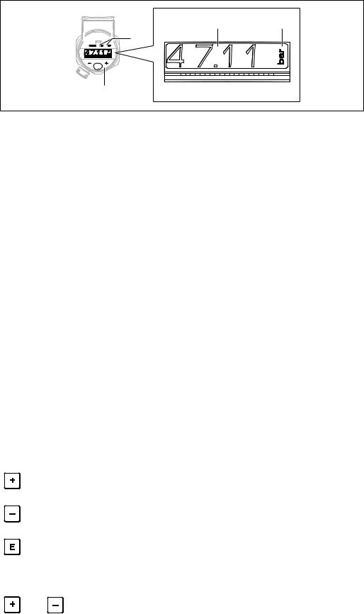
4 |
5 |


 3 2
3 2


 E
E 
1
A0022121
1 Operating keys
2Status LED
3 Switch output LEDs
4 Measured value
5Unit
The second switch output is not used for the device version with current output.
7.4General value adjustment and rejection of illegal entries
Parameter (not numerical value) is flashing: parameter can be adjusted or selected.
When adjusting a numerical value: the numerical value does not flash. The first digit of the numerical value starts to flash only when the key is pressed by way of confirmation. Enter the desired value with the or key and press the key to confirm. Following confirmation, the data are recorded directly and are active.
–Entry is OK: value is accepted and shown for one second on the display against a white background.
–Entry is not OK: the message "FAIL" appears for one second on the display against a red background. The value entered is rejected. In the event of an incorrect setting which affects the TD, an diagnostic message is displayed.
7.5Navigation and selection from list
The capacitive operating keys are used for navigation in the operating menu and to select an option from a picklist.
Operating key(s) |
Meaning |
|
|
|
|
|
|
• Navigate downwards in the picklist |
|
|
• Edit the numerical values or characters within a function |
A0017879 |
|
|
|
|
|
|
|
• Navigate upwards in the picklist |
|
|
• Edit the numerical values or characters within a function |
A0017880 |
|
|
|
|
|
|
|
• Confirm entry |
|
|
• Jump to the next item |
A0017881 |
|
• Select a menu item and activate the edit mode |
|
|
• The key lock function (KYL) is accessed by pressing the key for longer than 2 seconds |
|
|
|
Simultaneously |
ESC functions: |
|
|
|
• Exit edit mode for a parameter without saving the changed value. |
|
and |
• You are in a menu at a selection level. Each time you press the keys simultaneously, you |
|
go up a level in the menu. |
|
A0017879 |
A0017880 |
• Long ESC: press the keys for longer than 2 seconds |
|
|
|
24 |
Endress+Hauser |

Ceraphant PTC31B, PTP31B, PTP33B |
Operation options |
|
|
7.6Locking and unlocking operation
The device features
•Automatic key locking
•Parameter settings lock.
Key locking is indicated on the local display by "E > 2".
Locking of the parameter settings is indicated as soon as an attempt is made to change a parameter.
7.6.1Disabling the key lock
The keys are locked automatically if the device remains at the topmost menu level (display of pressure measurement value) for 60 seconds.
Call up the key lock function (KYL)
1.Press the key for at least 2 seconds and then release it
2.By confirming with "ON" is displayed
3.Use and to toggle between "ON" and "OFF"
4.Key locking is disabled as soon as is pressed to confirm "OFF"
The display changes to the main value level (topmost menu level) if the key is pressed briefly. The display changes to the key locking if the key is pressed for at least 2 seconds.
If in the case of "KYL", "ON" or "OFF", more than 10 seconds elapse without a key being pressed, you return to the topmost menu level with active key locking.
The function can be accessed anytime outside the main measured value display and within the operating menu, i.e. if the key is pressed for at least 2 seconds key locking can be performed anytime at any menu item. Locking is effective immediately. If you quit the context menu, you will return to the same point from which key locking was selected.
7.6.2Locking parameter settings
COD locking code
Navigation |
EF → ADM → COD |
Description |
A code can be entered to protect parameter settings against unauthorized and unwanted |
|
access. |
Selection |
To lock: Enter a number ¹ the LCK release code (value range: 1 to 9999). |
Factory setting |
0000 |
7.6.3 Unlocking parameter settings
If parameters are locked, the word "LCK" appears on the local display as soon as an attempt is made to change a parameter.
LCK unlocking code
Endress+Hauser |
25 |
Operation options |
Ceraphant PTC31B, PTP31B, PTP33B |
|
|
Navigation |
EF → ADM → LCK |
Description |
Use this function to enter the code (which was defined in the COD parameter) to enable |
|
configuration. |
|
Keys are evaluated but parameters are read only. The parameters can only be changed |
|
after unlocking. |
|
If an attempt is made to write to a parameter, a prompt for the device access code appears. |
|
To unlock, enter the user-defined device access code (which was specified in the COD |
|
parameter). |
User entry |
To unlock: Enter the access code. |
Factory setting |
0000 |
Note |
The access code is "0000" in the order configuration. Another access code can be defined in |
|
the parameter "COD". |
26 |
Endress+Hauser |
Loading...