


 Loading...
BA01894F/00/EN/02.19
71440978
2019-06-28
Valid as of version 01.00.zz
Products |
Solutions |
Services |
|
|
|
Operating Instructions
Liquiphant FTL51B
Vibronic
Limit switch for liquids
Liquiphant FTL51B
|
|
|
|
|
|
|
|
|
|
|
|
|
|
|
|
|
|
|
|
|
|
|
|
|
|
|
|
|
|
|
|
|
|
|
|
|
|
|
|
|
|
|
|
|
ORDER CODE: |
|
|
|
|
|
|
|
|
|
|
|
|
|
|
|
|
|
|
|
|
XXXXX-XXXXXX |
|
|
|
|
|
|
|
|
|
|
|
|
|
|
|
||
1. |
|
|
SER. NO.: |
|
|
|
|
|
|
|
|
|
|
|
|
|
|
|
|
|
|
XXXXXXXXXXXX |
|
|
|
|
|
|
|
|
|
|
|
|
|
|
|
||||
|
|
|
EXT. ORD. CD.: |
|
|
|
|
|
|
|
|
|
|
|
|
|
|
|
|
|
|
|
|
XXX.XXXX.XX |
|
|
|
|
|
|
|
|
|
|
|
|
|
|
|
||
|
|
|
|
|
|
|
|
|
|
|
|
|
|
|
|
|
|
|
|
|
|
|
|
|
|
|
|
|
|
|
|
|
|
|
|
|
|
|
|
|
|
|
|
|
|
|
|
|
|
|
|
|
|
|
|
|
|
|
|
|
|
|
|
|
|
|
|
|
|
|
|
|
|
|
|
|
|
|
|
|
|
|
|
|
|
|
|
|
|
|
|
|
|
|
|
|
|
|
|
|
|
|
|
|
|
|
|
|
|
|
|
|
|
|
|
|
|
|
|
|
|
|
|
|
|
|
|
|
|
|
|
|
|
|
|
|
|
|
|
|
|
|
|
|
|
|
|
|
|
Serial number |
|
|
|
|
|
|
|
|
|
|
|
|
|
|
|
|
|
|||||
|
|
|
|
|
|
|
|
|
|
|
|
|
2. |
www.endress.com/deviceviewer |
|
|
|
|
|
Endress+Hauser |
|||||
|
|
|
|
|
|
|
|
|
|
|
Operations App |
|
|
|
|
|
|
|
|
|
|
|
|
|
|
|
|
|
|
|
|
|
|
|
|
|
|
|
|
|
|
|
|
|
|
|
|
|
|
|
|
|
|
|
|
|
|
|
|
|
|
|
|
|
|
|
|
|
|
|
|
|
|
|
|
|
|
|
|
|
|
|
|
|
|
|
|
|
|
|
3.
A0023555
2 |
Endress+Hauser |

Liquiphant FTL51B |
Table of contents |
|
|
Table of contents
1 |
About this document . . . . . . . . . . . . . . . . |
5 |
|
1.1 |
Symbols |
. . . . . . . . . . . . . . . . . . . . . . . . . . . . . |
5 |
|
1.1.1 |
Safety symbols . . . . . . . . . . . . . . . . . . |
5 |
|
1.1.2 |
Electrical symbols . . . . . . . . . . . . . . . . |
5 |
|
1.1.3 Symbols for certain types of |
|
|
|
|
information . . . . . . . . . . . . . . . . . . . . |
5 |
|
1.1.4 |
Symbols in graphics . . . . . . . . . . . . . . . |
5 |
2 |
Basic safety instructions . . . . . . . . . . . . |
6 |
2.1 |
Requirements for the personnel . . . . . . . . . . . . |
6 |
2.2 |
Designated use . . . . . . . . . . . . . . . . . . . . . . . . |
6 |
|
2.2.1 Incorrect use . . . . . . . . . . . . . . . . . . . . |
6 |
2.3 |
Workplace safety . . . . . . . . . . . . . . . . . . . . . . . |
6 |
2.4 |
Operational safety . . . . . . . . . . . . . . . . . . . . . . |
6 |
2.5 |
Product safety . . . . . . . . . . . . . . . . . . . . . . . . . |
7 |
2.6 |
IT security . . . . . . . . . . . . . . . . . . . . . . . . . . . . |
7 |
3 |
Product description . . . . . . . . . . . . . . . . . |
7 |
3.1 |
Product design . . . . . . . . . . . . . . . . . . . . . . . . |
8 |
4Incoming acceptance and product
|
identification . . . . . . . . . . . . . . . . . . . . . . . |
9 |
|
4.1 |
Incoming acceptance . . . . . . . . . . . . . . . . . . . . |
9 |
|
4.2 |
Product identification . . . . . . . . . . . . . . . . . . . . |
9 |
|
|
4.2.1 |
Nameplate . . . . . . . . . . . . . . . . . . . . . |
9 |
|
4.2.2 |
Manufacturer address . . . . . . . . . . . . . |
9 |
4.3 |
Storage and transport . . . . . . . . . . . . . . . . . . |
10 |
|
|
4.3.1 |
Storage conditions . . . . . . . . . . . . . . . |
10 |
|
4.3.2 |
Transporting the device . . . . . . . . . . . |
10 |
5 |
Installation . . . . . . . . . . . . . . . . . . . . . . . |
11 |
|
5.1 |
Mounting conditions . . . . . . . . . . . . . . . . . . . |
11 |
|
|
5.1.1 Taking the switch point into |
|
|
|
|
consideration . . . . . . . . . . . . . . . . . . |
11 |
|
5.1.2 Take viscosity into consideration . . . . |
12 |
|
|
5.1.3 |
Avoiding buildup . . . . . . . . . . . . . . . . |
13 |
|
5.1.4 Take clearance into consideration . . . |
13 |
|
|
5.1.5 |
Support the device . . . . . . . . . . . . . . . |
14 |
5.1.6Weld-in adapter with leakage hole . . 14
5.2 Mounting the measuring device . . . . . . . . . . . 14 5.2.1 Required tools . . . . . . . . . . . . . . . . . . 14 5.2.2 Installation . . . . . . . . . . . . . . . . . . . . 15
5.3 Sliding sleeves . . . . . . . . . . . . . . . . . . . . . . . 16 5.4 Post-installation check . . . . . . . . . . . . . . . . . . 16
6 |
Electrical connection . . . . . . . . . . . . . . |
17 |
|
6.1 |
Connection conditions . . . . . . . . . . . . . . . . . . |
17 |
|
|
6.1.1 |
Cover with securing screw . . . . . . . . . |
17 |
|
6.1.2 |
Connecting protective earth (PE) . . . . |
17 |
Endress+Hauser
6.2 |
Connecting the measuring device . . . . . . . . . . |
17 |
|
6.2.1 2-wire AC (electronic insert |
|
FEL61) . . . . . . . . . . . . . . . . . . . . . . . 17
6.2.23-wire DC-PNP (electronic insert
FEL62) . . . . . . . . . . . . . . . . . . . . . . . 19
6.2.3Universal current connection with relay output (electronic insert
FEL64) . . . . . . . . . . . . . . . . . . . . . . . 21
6.2.4DC connection, relay output
(electronic insert FEL64 DC) . . . . . . . 23
6.2.5PFM output (electronic insert
FEL67) . . . . . . . . . . . . . . . . . . . . . . . 25
6.2.62-wire NAMUR > 2.2 mA/< 1.0 mA
(electronic insert FEL68) . . . . . . . . . . 27
6.2.7Bluetooth module VU121
(optional) . . . . . . . . . . . . . . . . . . . . . 29 6.2.8 LED module VU120 (optional) . . . . . . 30 6.2.9 Cable entry . . . . . . . . . . . . . . . . . . . . 30
6.3 Post-connection check . . . . . . . . . . . . . . . . . . 31
7 |
Operation options . . . . . . . . . . . . . . . . . |
32 |
7.1 Overview of operation options . . . . . . . . . . . . 32 7.1.1 Operating concept . . . . . . . . . . . . . . 32
7.1.2Functional test using the button on
the electronic insert . . . . . . . . . . . . . . 32
7.1.3Functional test of the electronic
switch with a test magnet . . . . . . . . . 35
7.1.4Heartbeat diagnostics and verification with Bluetooth® wireless
technology . . . . . . . . . . . . . . . . . . . . 36 7.2 LED module VU120 (optional) . . . . . . . . . . . . 37 7.2.1 Configuration and sensor status . . . . . 37
8 |
Commissioning . . . . . . . . . . . . . . . . . . . . |
37 |
8.1 Function check . . . . . . . . . . . . . . . . . . . . . . . 37 8.2 Switching on the measuring device . . . . . . . . . 38
8.3Establishing a connection via SmartBlue
(app) . . . . . . . . . . . . . . . . . . . . . . . . . . . . . . 38 8.3.1 SmartBlue (app) . . . . . . . . . . . . . . . . 38
9 |
Operation . . . . . . . . . . . . . . . . . . . . . . . . . |
40 |
|
9.1 |
Diagnostics menu . . . . . . . . . . . . . . . . . . . . . |
40 |
|
|
9.1.1 |
"Diagnostics" menu . . . . . . . . . . . . . . . |
40 |
|
9.1.2 |
"Application" menu . . . . . . . . . . . . . . |
40 |
|
9.1.3 |
"System" menu . . . . . . . . . . . . . . . . . . |
41 |
9.2 |
Heartbeat Verification . . . . . . . . . . . . . . . . . . |
42 |
|
9.3Recurrent testing for SIL/WHG (German
Water Resources Act) devices . . . . . . . . . . . . . 42
10 Diagnostics and troubleshooting . . . 42
10.1Diagnostic information via light emitting
diodes . . . . . . . . . . . . . . . . . . . . . . . . . . . . . . 43 10.1.1 LED at electronic insert . . . . . . . . . . . 43
3
Table of contents |
Liquiphant FTL51B |
|
|
10.1.2 SmartBlue . . . . . . . . . . . . . . . . . . . . . 43
11 |
Maintenance . . . . . . . . . . . . . . . . . . . . . . |
44 |
|
11.1 |
Maintenance tasks . . . . . . . . . . . . . . . . . . . . |
44 |
|
|
11.1.1 |
Cleaning . . . . . . . . . . . . . . . . . . . . . . |
44 |
12 |
Repair |
. . . . . . . . . . . . . . . . . . . . . . . . . . . . |
45 |
12.1 |
General information . . . . . . . . . . . . . . . . . . . |
45 |
|
|
12.1.1 |
Repair concept . . . . . . . . . . . . . . . . . |
45 |
|
12.1.2 Repair of Ex-certified devices . . . . . . . |
45 |
|
12.2 |
Spare parts . . . . . . . . . . . . . . . . . . . . . . . . . . |
45 |
|
12.3 |
Return . |
. . . . . . . . . . . . . . . . . . . . . . . . . . . . . |
45 |
12.4 |
Disposal |
. . . . . . . . . . . . . . . . . . . . . . . . . . . . |
46 |
13 |
Accessories . . . . . . . . . . . . . . . . . . . . . . . |
47 |
|
13.1 |
Device-specific accessories . . . . . . . . . . . . . . . |
47 |
|
|
13.1.1 |
Test magnet . . . . . . . . . . . . . . . . . . . |
47 |
|
13.1.2 Weather protection cover for dual- |
|
|
|
|
compartment housing, aluminum . . . |
47 |
|
13.1.3 Weather protection cover for single- |
|
|
|
|
compartment housing, metal . . . . . . . |
47 |
|
13.1.4 |
Plug-in jack . . . . . . . . . . . . . . . . . . . . |
48 |
|
13.1.5 |
Additional modules . . . . . . . . . . . . . . |
48 |
|
13.1.6 Sliding sleeves for unpressurized |
|
|
|
|
operation . . . . . . . . . . . . . . . . . . . . . |
49 |
|
13.1.7 High pressure sliding sleeves . . . . . . . |
50 |
|
14 |
Technical data . . . . . . . . . . . . . . . . . . . . |
52 |
|
14.1 |
Input . . |
. . . . . . . . . . . . . . . . . . . . . . . . . . . . . |
52 |
|
14.1.1 |
Measured variable . . . . . . . . . . . . . . |
52 |
|
14.1.2 |
Measuring range . . . . . . . . . . . . . . . |
52 |
14.2 |
Output . |
. . . . . . . . . . . . . . . . . . . . . . . . . . . . |
52 |
|
14.2.1 Output and input variants . . . . . . . . . |
52 |
|
|
14.2.2 |
Output signal . . . . . . . . . . . . . . . . . . |
53 |
|
14.2.3 |
Ex connection data . . . . . . . . . . . . . . |
53 |
14.3 |
Environment . . . . . . . . . . . . . . . . . . . . . . . . . |
53 |
|
|
14.3.1 |
Ambient temperature range . . . . . . . |
53 |
|
14.3.2 |
Storage temperature . . . . . . . . . . . . . |
54 |
|
14.3.3 |
Humidity . . . . . . . . . . . . . . . . . . . . . |
54 |
|
14.3.4 |
Operating altitude . . . . . . . . . . . . . . . |
55 |
|
14.3.5 |
Climate class . . . . . . . . . . . . . . . . . . |
55 |
|
14.3.6 |
Degree of protection . . . . . . . . . . . . . |
55 |
|
14.3.7 |
Vibration resistance . . . . . . . . . . . . . |
55 |
|
14.3.8 |
Shock resistance . . . . . . . . . . . . . . . . |
55 |
|
14.3.9 |
Mechanical load . . . . . . . . . . . . . . . . |
56 |
|
14.3.10 Electromagnetic compatibility . . . . . . |
56 |
|
14.4 |
Process . |
. . . . . . . . . . . . . . . . . . . . . . . . . . . . |
56 |
|
14.4.1 |
Process temperature range . . . . . . . . |
56 |
|
14.4.2 |
Thermal shock . . . . . . . . . . . . . . . . . |
56 |
|
14.4.3 |
Process pressure range . . . . . . . . . . . |
56 |
|
14.4.4 |
Test pressure . . . . . . . . . . . . . . . . . . |
57 |
|
14.4.5 |
Density . . . . . . . . . . . . . . . . . . . . . . |
57 |
|
14.4.6 |
Pressure tightness . . . . . . . . . . . . . . |
58 |
14.5 |
Additional technical data . . . . . . . . . . . . . . . . |
58 |
|
Index . . . . . . |
. . . . . . . . . . . . . . . . . . . . . . . . . . . . |
59 |
|
4 |
Endress+Hauser |

Liquiphant FTL51B |
About this document |
|
|
1About this document
1.1Symbols
1.1.1Safety symbols
 DANGER
This symbol alerts you to a dangerous situation. Failure to avoid this situation will result in serious or fatal injury.
 WARNING
This symbol alerts you to a dangerous situation. Failure to avoid this situation can result in serious or fatal injury.
 CAUTION
This symbol alerts you to a dangerous situation. Failure to avoid this situation can result in minor or medium injury.
NOTICE
This symbol contains information on procedures and other facts which do not result in personal injury.
1.1.2Electrical symbols
 Ground connection
Grounded clamp, which is grounded via a grounding system.
 Protective earth (PE)
Ground terminals, which must be grounded prior to establishing any other connections.
The ground terminals are located on the inside and outside of the device.
1.1.3Symbols for certain types of information
 Permitted
Procedures, processes or actions that are permitted.
 Forbidden
Procedures, processes or actions that are forbidden.
 Tip
Tip
Indicates additional information
 Reference to documentation
A  Reference to another section
1. , 2. , 3. Series of steps
1.1.4Symbols in graphics
A, B, C ... View
1, 2, 3 ... Item numbers - Hazardous area
. Safe area (non-hazardous area)
Endress+Hauser |
5 |
Basic safety instructions |
Liquiphant FTL51B |
|
|
2Basic safety instructions
2.1Requirements for the personnel
The personnel must fulfill the following requirements to carry out the necessary tasks, e. g., commissioning and maintenance:
Trained, qualified specialists must have a relevant qualification for the specific function and task
Are authorized by the plant owner/operator
Are familiar with federal/national regulations
Must have read and understood the instructions in the manual and supplementary documentation
Follow instructions and comply with conditions
2.2Designated use
•Only use the measuring device as a limit switch for liquids
•Improper use can pose hazards
•Ensure that the measuring device is free of defects while it is in operation
•Use the measuring device only for media to which the process-wetted materials have an adequate level of resistance
•Do not exceed or drop below the limit values for the measuring deviceTI01403F/00/EN
2.2.1Incorrect use
The manufacturer is not liable for damage caused by improper or non-designated use.
Residual risks
Due to heat transfer from the process, the temperature of the electronics housing and the assemblies contained therein may rise to 80 °C (176 °F) during operation.
Danger of burns from contact with surfaces!
If necessary, ensure protection against contact to prevent burns.
For requirements concerning functional safety in accordance with IEC 61508, the associated SIL documentation must be observed.
2.3Workplace safety
For work on and with the device:
Wear the required protective equipment according to federal/national regulations.
2.4Operational safety
Risk of injury!
Operate the device only if it is in proper technical condition, free from errors and faults.
The operator is responsible for ensuring failure-free operation of the device.
Modifications to the device
Unauthorized modifications to the device are not permitted and can lead to unforeseeable dangers.
If, despite this, modifications are required, consult with Endress+Hauser.
6 |
Endress+Hauser |
Liquiphant FTL51B |
Product description |
|
|
Repair
To ensure continued operational safety and reliability:
Only perform repair work on the device if this is expressly permitted.
Observe federal/national regulations pertaining to the repair of an electrical device.
Use original spare parts and accessories from Endress+Hauser only.
2.5Product safety
This measuring device is designed in accordance with good engineering practice to meet state-of-the-art safety requirements, has been tested, and left the factory in a condition in which it is safe to operate.
It meets general safety standards and legal requirements. It also complies with the EC directives listed in the device-specific EC Declaration of Conformity. Endress+Hauser confirms this by affixing the CE mark to the device.
2.6IT security
We only provide a warranty if the device is installed and used as described in the Operating Instructions. The device has safety mechanisms integrated to prevent users from inadvertently changing settings.
Provide additional protection for the device and data transfer to/from the device
IT security measures defined in the plant owner/operator's own security policy must be implemented by plant owners/operators themselves.
3Product description
Point level switch for minimum or maximum detection.
Endress+Hauser |
7 |

Product description |
Liquiphant FTL51B |
|
|
3.1Product design
1
2
3
4 |
5 |
A0036953
1 Product design
1Housing with electronic insert and cover, optional Bluetooth module or LED module
2 Optional spacer (temperature spacer or pressure-tight feedthrough (second line of defense))
3Compact probe design
4 Probe design with pipe extension
5Probe design with short pipe
 Identify the electronic insert via the order code on the nameplate.
Optional: Bluetooth module VU121 or LED module VU120
FCC |
C |
|
IC: |
ID: |
ONTAINS |
A0039257
2 Bluetooth module
A0039258
3 LED module
8 |
Endress+Hauser |

Liquiphant FTL51B |
Incoming acceptance and product identification |
|
|
4Incoming acceptance and product identification
4.1Incoming acceptance
Check the following during goods acceptance:
Are the order codes on the delivery note and the product sticker identical?
Are the goods undamaged?
Do the nameplate data match the ordering information on the delivery note?
If required (see nameplate): Are the Safety Instructions, e. g. XA, provided?
Is the device properly secured?
 If one of these conditions is not met, please contact the manufacturer's sales office.
4.2Product identification
The measuring device can be identified in the following ways:
•Nameplate data
•Extended order code with breakdown of the device features on the delivery note
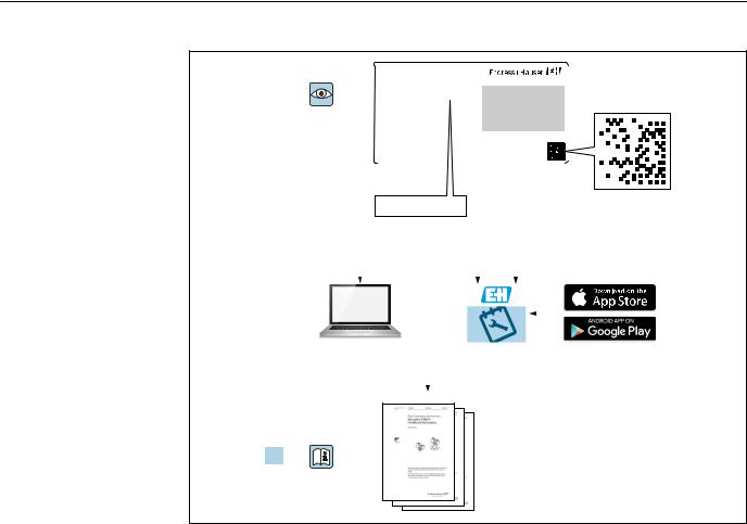
•Enter serial number from nameplates in W@M Device Viewer (www.endress.com/deviceviewer): All of the information on the measuring device is displayed along with an overview of the scope of technical documentation provided
•Enter the serial number on the nameplate into the Endress+Hauser Operations App or use the Endress+Hauser Operations App to scan the 2-D matrix code (QR Code) on the nameplate
4.2.1 |
Nameplate |
|
|
|
|
ORDER CODE: |
3 |
|
SER. NO.: |
|
EXT. ORD. CD.: |
|
|
|
|
PMAX: |
|
|
|
|
0.83 W PNP |
|
|
|
|
|
|
4 |
5 |
|
L: |
|
|
|
|
DEV.REV.: |
|
|
|
1 |
2 FW: |
|
|
|
|
|
|
4 |
|
|
|
|
|
A0038187 |
4 Nameplate specifications
1 Manufacturer name and device name
2Manufacturer address
3 Order number, external order code, serial number
4Technical data
5Approval-specific information
4.2.2Manufacturer address
Endress+Hauser SE+Co. KG Hauptstraße 1
79689 Maulburg, Germany
Address of the manufacturing plant: See nameplate.
Endress+Hauser |
9 |
Incoming acceptance and product identification |
Liquiphant FTL51B |
|
|
4.3Storage and transport
4.3.1Storage conditions
Use original packaging.
Storage temperature
–40 to +80 °C (–40 to +176 °F) optional: –52 °C (–62 °F), –60 °C (–76 °F)
4.3.2Transporting the device
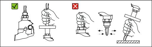
•Transport the device to the measuring point in the original packaging
•Hold the device by the housing, temperature spacer, flange or extension pipe
•Do not bend, shorten or extend the tuning fork
A0034846
5 Handling the device during transportation
10 |
Endress+Hauser |
Liquiphant FTL51B |
Installation |
|
|
5Installation
LWARNING
Loss of protection rating if the device is opened in a wet environment.
Only open the device in a dry environment!
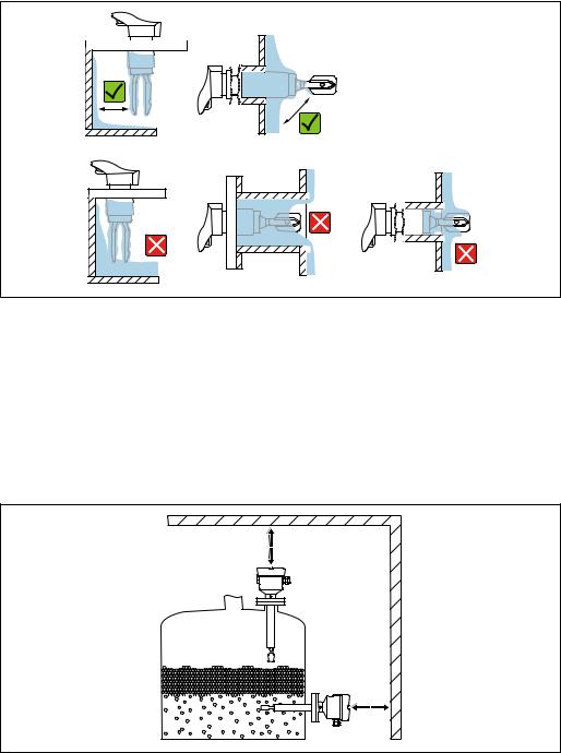
1 |
A0037879 |
6 Installation in any position in a vessel, pipe or tank
1Temperature spacer for tank with insulation and/or high process temperatures
5.1Mounting conditions
5.1.1Taking the switch point into consideration
Typical switch points, depending on the orientation of the point level switch
(water +23 °C (+73 °F))
A
(0.5)~13
D
B
D 
~4 (0.16)
D
~12.5 (0.49)
C
A0037915
7 Typical switch points. Unit of measurement mm (in)
A Installation from above B Installation from below C Installation from the side
DSwitch point
Endress+Hauser |
11 |

Installation |
Liquiphant FTL51B |
|
|
5.1.2Take viscosity into consideration
Low viscosity
D |
> 25 (0.98)
A0033297
8 Installation example for low-viscosity liquids. Unit of measurement mm (in)
DDiameter of installation socket: at least 50 mm (2.0 in)
 Low viscosity, e. g. water: < 2 000 mPa s
It is permitted to position the tuning fork within the installation socket.
High viscosity
> 40 (1.57)
A0037348
9 Installation example for a highly viscous liquid. Unit of measurement mm (in)
NOTICE
Highly viscous liquids may cause switching delays.
Make sure that the liquid can run off the tuning fork easily.
Deburr the socket surface.
High viscosity, e. g. viscous oils: < 10 000 mPa s
The tuning fork must be located outside the installation socket!
12 |
Endress+Hauser |
Liquiphant FTL51B |
Installation |
|
|
5.1.3Avoiding buildup
A0033239
10 Installation examples for a highly viscous process medium
•Use short installation sockets to ensure that the turning fork can project freely into the vessel.
•Install preferably flush-mounted on vessels or in pipes.
•Leave sufficient distance between the buildup expected on the tank wall and the tuning fork.
5.1.4Take clearance into consideration
A0033236
11 Take clearance into consideration
Allow sufficient space outside the tank for mounting, connection and settings involving the electronic insert.
Endress+Hauser |
13 |

Installation |
Liquiphant FTL51B |
|
|
5.1.5Support the device
A0031874
12 Support in the event of dynamic load
Support the device in the event of severe dynamic load. Maximum lateral loading capacity of the pipe extensions and sensors: 75 Nm (55 lbf ft).
5.1.6Weld-in adapter with leakage hole
316L
A0039230
13 Weld-in adapter with leakage hole
Weld in the welding neck in such a way that the leakage hole is pointing downwards. This enables any leaks to be detected quickly.
5.2Mounting the measuring device
5.2.1Required tools
•Open-ended wrench for sensor installation
•Screwdriver for electrical connection
14 |
Endress+Hauser |

Liquiphant FTL51B |
Installation |
|
|
5.2.2Installation
Horizontal installation in vessels
Align the tuning fork with the marking
316L/G1 |
A0039125 |
14 Marking to align the tuning fork
Use the marking to align the tuning fork in such a way that medium can run off easily and deposit buildup is avoided.
The following can be used as the marking:
•Material specification, thread description or circle on the hexagonal nut or on the weldin adapter
•The II symbol on the back of the flange or Tri-Clamp
Installing in pipes
A0034851 |
15 Marking and fork position |
•Flow velocity up to 5 m/s with viscosity 1 mm2/s (cSt) and density 1 g/cm3 (SGU) Check for correct functioning in the event of other process medium conditions
•The marking on the adapter points in the flow direction; the flow is thus not severely obstructed
•The marking can be identified while the device is installed
Screwing in the device
A0034852
16 Screwing in the device
•Turn by the hex bolt only, 15 to 30 Nm (11 to 22 lbf ft)
•Do not turn at the housing!
Endress+Hauser |
15 |

Installation |
Liquiphant FTL51B |
|
|
Aligning the cable entry
1. |
3. |
2. |
|
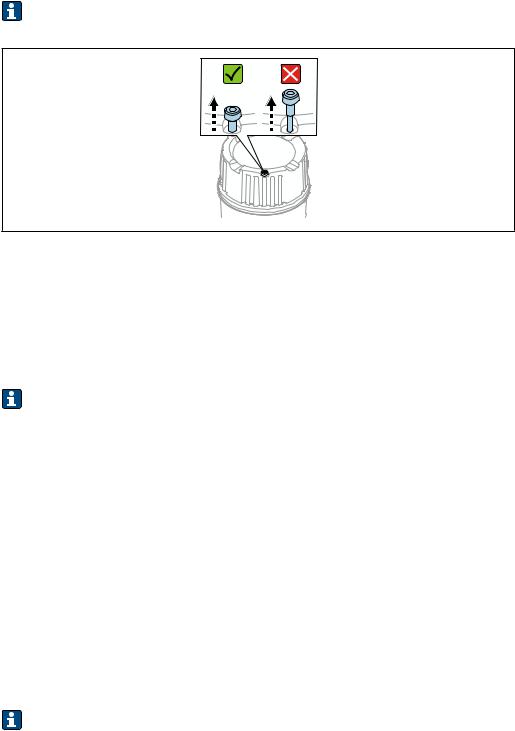
3 |
3 0.7 NM |
A0037347
17 Housing with external locking screw
 The locking screw is not tightened when the device is delivered.
1.Release the external locking screw.
2.Turn the housing, align the cable entry.
3.Tighten the external locking screw.
5.3Sliding sleeves
See the "Accessories" section.
5.4Post-installation check
Is the measuring device undamaged (visual inspection)?
Does the measuring device conform to the measuring point specifications?
For example:
•Process temperature
•Process pressure
•Ambient temperature range
•Measuring range
Are the measuring point number and labeling correct (visual inspection)?
Is the measuring device adequately protected against precipitation and direct sunlight?Is the device properly secured?
16 |
Endress+Hauser |
Liquiphant FTL51B |
Electrical connection |
|
|
6Electrical connection
6.1Connection conditions
6.1.1Cover with securing screw
Covers with a securing screw are available for devices for use in hazardous areas. Do not release the screw fully.
A0039520
18 Cover with securing screw
6.1.2Connecting protective earth (PE)
The protective earth conductor at the device must only be connected if the device's operating voltage is ≥ 35 VDC or ≥ 16 VACeff.
When the device is used in hazardous areas, it must always be included in the potential equalization of the system, irrespective of the operating voltage.
The plastic housing is available with or without an external protective earth connection (PE).
6.2Connecting the measuring device
6.2.12-wire AC (electronic insert FEL61)
•Two-wire AC version
•Switches the load directly into the power supply circuit via an electronic switch; always connect in series with a load.
•Functional testing without level change
A functional test can be performed on the device using the test button on the electronic insert.
Supply voltage
U = 19 to 253 VAC
Residual voltage when switched through: maximum 12 V
Pay attention to the following as per IEC/EN61010-1: Provide a suitable circuit breaker for the device, and limit the current to 1 A, e. g. by installing a 1 A fuse (slowblow) in the line (not the neutral wire) of the supply circuit.
Power consumption
P ≤ 2 VA
Endress+Hauser |
17 |

Electrical connection |
Liquiphant FTL51B |
|
|
Current consumption
Residual current when blocked: I ≤ 3.8 mA
The red LED flashes in the event of an overload or short-circuit. Check for an overload or short-circuit every 5 seconds. The test is deactivated after 60 seconds.
Power output and load current
•Max 89 VA/253 V (350 mA); max 8.4 VA/24 V (350 mA)
•Min 2.5 VA/253 V (10 mA); min ≥ 0.5 VA/24 V (20 mA)
•With overload and short-circuit protection.
Behavior of output signal
•OK status: load on (switched through)
•Demand mode: load off (blocked)
•Alarm: load off (blocked)
Terminal assignment
Always connect an external load. The electronic insert has integrated short-circuit protection.
|
|
U ~ 19...253 V AC |
|
|
|
I MAX: 350 MA |
|
|
|
L1 |
N |
COM |
MAX |
>0,7 |
|
|
|
|
|
|
|
>0,5 |
|
|
MIN |
|
|
|
1 |
|
|
|
2 |
1 |
2 |
|
|
||


 !
!
1 A
K
PE |
L1 N |
A0036060
19 2-wire AC, electronic insert FEL61
18 |
Endress+Hauser |
Loading...