


 Loading...
TI01133P/00/EN/06.18
71404630
Products |
Solutions |
Services |
|
|
|
Technical Information
Cerabar PMC11, PMC21,
PMP11, PMP21
Process pressure measurement
Pressure transducer with ceramic and metal sensors
Application
The Cerabar is a pressure transducer for the measurement of absolute and gauge pressure in gases, vapors, liquids and dust. The Cerabar can be used internationally thanks to a wide range of approvals and process connections.
Your benefits
•High reproducibility and long-term stability
•Reference accuracy: up to 0.3%
•Customized measuring ranges
–Turn down up to 5:1
–Sensor for measuring ranges up to 400 bar (6 000 psi)
•Housing and process isolating diaphragm made of 316L

Cerabar PMC11, PMC21, PMP11, PMP21
Table of contents
Document information . . . . . . . . . . . . . . . . . . . . . . . 4
Document function . . . . . . . . . . . . . . . . . . . . . . . . . . . . 4 Symbols used . . . . . . . . . . . . . . . . . . . . . . . . . . . . . . . . 4 Documentation . . . . . . . . . . . . . . . . . . . . . . . . . . . . . . . 5 Terms and abbreviations . . . . . . . . . . . . . . . . . . . . . . . . 6 Turn down calculation . . . . . . . . . . . . . . . . . . . . . . . . . . 7
Function and system design . . . . . . . . . . . . . . . . . . . 8
Measuring principle - process pressure measurement . . . . . |
8 |
Measuring system . . . . . . . . . . . . . . . . . . . . . . . . . . . . . |
8 |
Device features . . . . . . . . . . . . . . . . . . . . . . . . . . . . . . . |
9 |
Product design . . . . . . . . . . . . . . . . . . . . . . . . . . . . . . |
11 |
System integration . . . . . . . . . . . . . . . . . . . . . . . . . . . |
12 |
Input . . . . . . . . . . . . . . . . . . . . . . . . . . . . . . . . . . . . 13
Measured variable . . . . . . . . . . . . . . . . . . . . . . . . . . . . 13 Measuring range . . . . . . . . . . . . . . . . . . . . . . . . . . . . 13
Output . . . . . . . . . . . . . . . . . . . . . . . . . . . . . . . . . . 16
Output signal . . . . . . . . . . . . . . . . . . . . . . . . . . . . . . . 16 Signal range 4 to 20 mA . . . . . . . . . . . . . . . . . . . . . . . . 16 Load (for 4 to 20 mA devices ) . . . . . . . . . . . . . . . . . . . . 16 Load resistance (for 0 to 10 V devices) . . . . . . . . . . . . . . 16 Signal on alarm 4 to 20 mA . . . . . . . . . . . . . . . . . . . . . . 16 Dead time, time constant . . . . . . . . . . . . . . . . . . . . . . . 16 Dynamic behavior . . . . . . . . . . . . . . . . . . . . . . . . . . . . 17
Power supply . . . . . . . . . . . . . . . . . . . . . . . . . . . . . 18
Terminal assignment . . . . . . . . . . . . . . . . . . . . . . . . . . 18 Supply voltage . . . . . . . . . . . . . . . . . . . . . . . . . . . . . . 18 Current consumption and alarm signal . . . . . . . . . . . . . . 18 Power supply fault . . . . . . . . . . . . . . . . . . . . . . . . . . . . 19 Electrical connection . . . . . . . . . . . . . . . . . . . . . . . . . . 19 Cable specification . . . . . . . . . . . . . . . . . . . . . . . . . . . . 19 Residual ripple . . . . . . . . . . . . . . . . . . . . . . . . . . . . . . 19 Influence of power supply . . . . . . . . . . . . . . . . . . . . . . . 19 Overvoltage protection . . . . . . . . . . . . . . . . . . . . . . . . 19
Performance characteristics of ceramic process isolating diaphragm . . . . . . . . . . . . . . . . . . . . . . . . 20
Reference operating conditions . . . . . . . . . . . . . . . . . . . 20 Measuring uncertainty for small absolute pressure
measuring ranges . . . . . . . . . . . . . . . . . . . . . . . . . . . . 20 Influence of the installation position . . . . . . . . . . . . . . . . 20 Resolution . . . . . . . . . . . . . . . . . . . . . . . . . . . . . . . . . 20 Reference accuracy . . . . . . . . . . . . . . . . . . . . . . . . . . . 20 Thermal change of the zero output and the output span . . . 20 Long-term stability . . . . . . . . . . . . . . . . . . . . . . . . . . . 21 Switch-on time . . . . . . . . . . . . . . . . . . . . . . . . . . . . . . 21
Performance characteristics of metal process
isolating diaphragm . . . . . . . . . . . . . . . . . . . . . . . . 22
Reference operating conditions . . . . . . . . . . . . . . . . . . . 22 Measuring uncertainty for small absolute pressure
measuring ranges . . . . . . . . . . . . . . . . . . . . . . . . . . . . 22 Influence of the installation position . . . . . . . . . . . . . . . . 22 Resolution . . . . . . . . . . . . . . . . . . . . . . . . . . . . . . . . . 22
Reference accuracy . . . . . . . . . . . . . . . . . . . . . . . . . . . 22 Thermal change of the zero output and the output span . . . 22 Long-term stability . . . . . . . . . . . . . . . . . . . . . . . . . . . 22 Switch-on time . . . . . . . . . . . . . . . . . . . . . . . . . . . . . . 22
Installation . . . . . . . . . . . . . . . . . . . . . . . . . . . . . . . 23
Installation conditions . . . . . . . . . . . . . . . . . . . . . . . . . 23 Influence of the installation position . . . . . . . . . . . . . . . . 23 Mounting location . . . . . . . . . . . . . . . . . . . . . . . . . . . . 23 Mounting instructions for oxygen applications . . . . . . . . . 24
Environment . . . . . . . . . . . . . . . . . . . . . . . . . . . . . . 26
Ambient temperature range . . . . . . . . . . . . . . . . . . . . . 26 Storage temperature range . . . . . . . . . . . . . . . . . . . . . . 26 Climate class . . . . . . . . . . . . . . . . . . . . . . . . . . . . . . . 26 Degree of protection . . . . . . . . . . . . . . . . . . . . . . . . . . 26 Vibration resistance . . . . . . . . . . . . . . . . . . . . . . . . . . . 26 Electromagnetic compatibility . . . . . . . . . . . . . . . . . . . . 26
Process . . . . . . . . . . . . . . . . . . . . . . . . . . . . . . . . . . 27
Process temperature range for devices with ceramic
process isolating diaphragm . . . . . . . . . . . . . . . . . . . . . 27 Process temperature range for devices with metallic
process isolating diaphragm . . . . . . . . . . . . . . . . . . . . . 27 Pressure specifications . . . . . . . . . . . . . . . . . . . . . . . . . 28
Mechanical construction . . . . . . . . . . . . . . . . . . . . 29
Design, dimensions . . . . . . . . . . . . . . . . . . . . . . . . . . . 29 Electrical connection . . . . . . . . . . . . . . . . . . . . . . . . . . 29 Housing . . . . . . . . . . . . . . . . . . . . . . . . . . . . . . . . . . . 30 Process connections with internal, ceramic process
isolating diaphragm . . . . . . . . . . . . . . . . . . . . . . . . . . . 32 Process connections with internal, ceramic process
isolating diaphragm . . . . . . . . . . . . . . . . . . . . . . . . . . . 33 Process connections with internal, ceramic process
isolating diaphragm . . . . . . . . . . . . . . . . . . . . . . . . . . . 34 Process connections with internal, ceramic process
isolating diaphragm . . . . . . . . . . . . . . . . . . . . . . . . . . . 34 Process connections with internal, metal process isolating diaphragm . . . . . . . . . . . . . . . . . . . . . . . . . . . . . . . . . 35 Process connections with internal, metal process isolating diaphragm . . . . . . . . . . . . . . . . . . . . . . . . . . . . . . . . . 36 Process connections with internal, metal process isolating diaphragm . . . . . . . . . . . . . . . . . . . . . . . . . . . . . . . . . 37 Process connections with internal, metal process isolating diaphragm . . . . . . . . . . . . . . . . . . . . . . . . . . . . . . . . . 37 Process connections with flush-mounted, metal process isolating diaphragm . . . . . . . . . . . . . . . . . . . . . . . . . . . 38 Materials in contact with process . . . . . . . . . . . . . . . . . . 39 Materials not in contact with process . . . . . . . . . . . . . . . 40 Cleaning . . . . . . . . . . . . . . . . . . . . . . . . . . . . . . . . . . 41
Operability . . . . . . . . . . . . . . . . . . . . . . . . . . . . . . . 42
Plug-on display PHX20 (optional) . . . . . . . . . . . . . . . . . . 42
Certificates and approvals . . . . . . . . . . . . . . . . . . . 43
CE mark . . . . . . . . . . . . . . . . . . . . . . . . . . . . . . . . . . . 43
2 |
Endress+Hauser |

Cerabar PMC11, PMC21, PMP11, PMP21
RoHS . . . . . . . . . . . . . . . . . . . . . . . . . . . . . . . . . . . . . 43 RCM-Tick marking . . . . . . . . . . . . . . . . . . . . . . . . . . . . 43 EAC conformity . . . . . . . . . . . . . . . . . . . . . . . . . . . . . . 43 Approval . . . . . . . . . . . . . . . . . . . . . . . . . . . . . . . . . . 43 Safety Instructions (XA) . . . . . . . . . . . . . . . . . . . . . . . . 43 Marine approval (pending) . . . . . . . . . . . . . . . . . . . . . . 44 Pressure Equipment Directive 2014/68/EU (PED) . . . . . . . 44 Other standards and guidelines . . . . . . . . . . . . . . . . . . . 44 CRN approval . . . . . . . . . . . . . . . . . . . . . . . . . . . . . . . 45 Calibration unit . . . . . . . . . . . . . . . . . . . . . . . . . . . . . . 45 Calibration . . . . . . . . . . . . . . . . . . . . . . . . . . . . . . . . . 45 Inspection certificates . . . . . . . . . . . . . . . . . . . . . . . . . . 45
Ordering information . . . . . . . . . . . . . . . . . . . . . . . 46
Scope of delivery . . . . . . . . . . . . . . . . . . . . . . . . . . . . . 46
Accessories . . . . . . . . . . . . . . . . . . . . . . . . . . . . . . . 47
Weld-in adapter . . . . . . . . . . . . . . . . . . . . . . . . . . . . . 47 Plug-on display PHX20 . . . . . . . . . . . . . . . . . . . . . . . . . 47 M12 plug connectors . . . . . . . . . . . . . . . . . . . . . . . . . . 47
Documentation . . . . . . . . . . . . . . . . . . . . . . . . . . . . |
48 |
Field of Activities . . . . . . . . . . . . . . . . . . . . . . . . . . . . |
48 |
Technical Information . . . . . . . . . . . . . . . . . . . . . . . . . |
48 |
Operating Instructions . . . . . . . . . . . . . . . . . . . . . . . . . |
48 |
Brief Operating Instructions . . . . . . . . . . . . . . . . . . . . . |
48 |
Safety Instructions (XA) . . . . . . . . . . . . . . . . . . . . . . . . |
48 |
Endress+Hauser |
3 |

|
|
|
|
|
|
|
Cerabar PMC11, PMC21, PMP11, PMP21 |
|
|
|
|
|
|
|
|
|
Document information |
||||||
|
|
|
|
|
|
|
|
Document function |
The document contains all the technical data on the device and provides an overview of the |
||||||
|
accessories and other products that can be ordered for the device. |
||||||
|
|
|
|
||||
Symbols used |
Safety symbols |
|
|
||||
|
|
|
|
|
|
|
|
|
|
Symbol |
|
Meaning |
|||
|
|
|
|
|
|
|
|
|
|
|
|
|
|
|
DANGER! |
|
|
DANGER |
|
|
|
This symbol alerts you to a dangerous situation. Failure to avoid this situation will result in |
|
|
|
|
|
|
|
|
serious or fatal injury. |
|
|
|
|
|
|
|
|
|
|
|
|
|
|
|
WARNING! |
|
|
WARNING |
|
This symbol alerts you to a dangerous situation. Failure to avoid this situation can result in |
|||
|
|
|
|
|
|
|
serious or fatal injury. |
|
|
|
|
|
|
|
|
|
|
|
|
|
|
|
CAUTION! |
|
|
CAUTION |
|
|
This symbol alerts you to a dangerous situation. Failure to avoid this situation can result in |
||
|
|
|
|
|
|
|
minor or medium injury. |
|
|
|
|
|
|
|
|
|
|
|
|
|
|
|
NOTICE! |
|
|
NOTICE |
|
|
This symbol contains information on procedures and other facts which do not result in |
||
|
|
|
|
|
|
|
personal injury. |
|
|
|
|
|
|
|
|
Electrical symbols
Symbol |
Meaning |
Symbol |
Meaning |
|
|
|
|
|
Protective ground connection |
|
Ground connection |
|
A terminal which must be connected |
|
A grounded terminal which, as far as |
|
to ground prior to establishing any |
|
the operator is concerned, is |
|
other connections. |
|
grounded via a grounding system. |
|
|
|
|
Symbols for certain types of information
Symbol Meaning
Permitted
Procedures, processes or actions that are permitted.
Forbidden
Procedures, processes or actions that are forbidden.
Tip
Indicates additional information.
Reference to documentation
A |
Reference to page |
Reference to graphic
Visual inspection
Symbols in graphics
|
Symbol |
Meaning |
|||||
|
|
|
|
|
|
|
|
1, 2, 3 ... |
Item numbers |
||||||
|
|
|
|
|
|
|
|
|
|
|
|
|
|
|
Series of steps |
|
1. |
, |
2. |
, |
3. |
… |
|
|
|
||||||
A, B, C, ... |
Views |
||||||
|
|
|
|
|
|
|
|
4 |
Endress+Hauser |

Cerabar PMC11, PMC21, PMP11, PMP21
Documentation |
The document types listed are available: |
|
In the Download Area of the Endress+Hauser Internet site: www.endress.com → Download |
|
Brief Operating Instructions (KA): getting the 1st measured value quickly |
|
These instructions contain all the essential information from incoming acceptance to initial |
|
commissioning. |
Operating Instructions (BA): your comprehensive reference
These Operating Instructions contain all the information that is required in various phases of the life cycle of the device: from product identification, incoming acceptance and storage, to mounting, connection, operation and commissioning through to troubleshooting, maintenance and disposal.
Safety Instructions (XA)
Depending on the approval, the following Safety Instructions (XA) are supplied with the device. They are an integral part of the Operating Instructions.
Device |
Directive |
Documentation |
Option 1) |
PMP21 |
ATEX II 1/2G Ex ia IIC T4 Ga/Gb |
XA01271P |
BA |
|
|
|
|
PMC21 |
ATEX II 2G Ex ia IIC T4 Gb |
XA01271P |
BB |
|
|
|
|
PMC21 |
ATEX II 3G Ex ec IIC T4 Gc |
XA01533P |
BC |
PMP21 |
|
|
|
|
|
|
|
PMC21 |
FM IS Cl. I, Div.1 Gr. A-D T4 |
XA01321P |
FA |
PMP21 |
|
|
|
|
|
|
|
PMC21 |
CSA C/US IS Cl. I Div. 1 Gr. A-D |
XA01322P |
CB |
PMP21 |
|
|
|
|
|
|
|
PMC21 |
EAC Ex ia IIC T4 Ga/Gb |
XA01540P |
GA |
PMP21 |
|
|
|
|
|
|
|
PMC21 |
IEC Ex ia IIC T4 Ga/Gb |
XA01271P |
IA |
PMP21 |
|
|
|
|
|
|
|
PMC21 |
NEPSI Ex ia IIC T4 |
XA01363P |
NA |
PMP21 |
|
|
|
|
|
|
|
PMC21 |
TIIS Ex ia IIC T4 |
In preparation |
TA |
PMP21 |
|
|
|
|
|
|
|
1)Product Configurator order code for "Approval"
 The nameplate indicates the Safety Instructions (XA) that are relevant to the device.
Endress+Hauser |
5 |
|
|
|
Cerabar PMC11, PMC21, PMP11, PMP21 |
||
Terms and abbreviations |
|
|
|
|
|
|
|
|
1 |
|
|
|
|
|
2 |
|
|
|
|
3 |
|
|
|
|
|
4 |
|
|
|
|
|
|
|
|
P |
|
0 |
|
|
|
|
LRL |
LRV |
URV |
URL |
MWP |
OPL |
|
|
|
|
|
A0029505 |
Item |
Term/ |
Explanation |
|
abbreviation |
|
|
|
|
1 |
OPL |
The OPL (over pressure limit = sensor overload limit) for the measuring device |
|
|
depends on the lowest-rated element, with regard to pressure, of the selected |
|
|
components, i.e. the process connection has to be taken into consideration in |
|
|
addition to the measuring cell. Also observe pressure-temperature dependency. For |
|
|
the relevant standards and additional notes, see the "Pressure specifications" section |
|
|
→ 28 . |
|
|
The OPL may only be applied for a limited period of time. |
|
|
|
2 |
MWP |
The MWP (maximum working pressure) for the sensors depends on the lowest- |
|
|
rated element, with regard to pressure, of the selected components, i.e. the process |
|
|
connection has to be taken into consideration in addition to the measuring cell. |
|
|
Also observe pressure-temperature dependency. For the relevant standards and |
|
|
additional notes, see the "Pressure specifications" section → 28 . |
|
|
The MWP may be applied at the device for an unlimited period. |
|
|
The MWP can also be found on the nameplate. |
|
|
|
3 |
Maximum sensor |
Span between LRL and URL |
|
measuring range |
This sensor measuring range is equivalent to the maximum calibratable/adjustable |
|
|
span. |
|
|
|
4 |
Calibrated/ |
Span between LRV and URV |
|
adjusted span |
Factory setting: 0 to URL |
|
|
Other calibrated spans can be ordered as customized spans. |
|
|
|
p |
- |
Pressure |
|
|
|
- |
LRL |
Lower range limit |
|
|
|
- |
URL |
Upper range limit |
|
|
|
- |
LRV |
Lower range value |
|
|
|
- |
URV |
Upper range value |
|
|
|
- |
TD (turn down) |
Turn down |
|
|
The turn down is preset at the factory and cannot be changed. |
|
|
Example - see the following section. |
|
|
|
6 |
Endress+Hauser |

Cerabar PMC11, PMC21, PMP11, PMP21
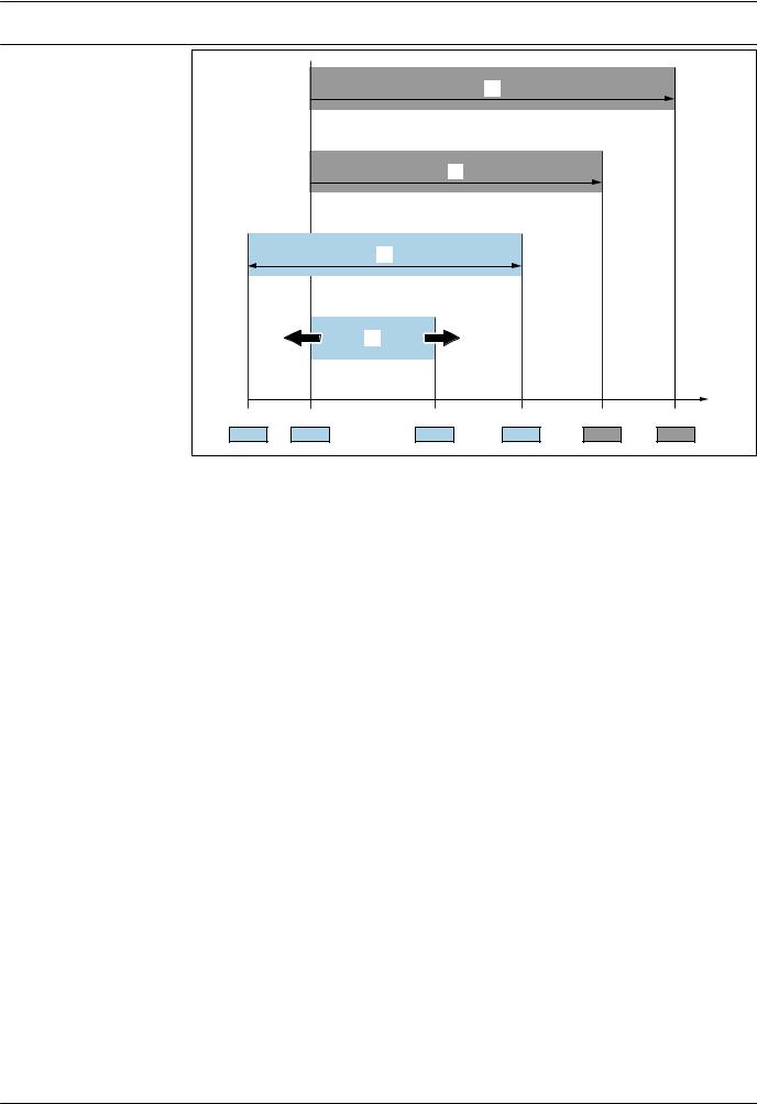
Turn down calculation |
|
|
|
|
|
|
|
1 = 2 |
|
|
3 |
||
|
|
|
|
|
|
|
|
|
|
|
|||
|
|
|
|
|
LRL LRV |
|
URV |
URL |
|||||
|
|
|
|
|
|
|
|
|
|
|
|
|
|
|
|
|
|
|
|
|
|
|
|
|
|
|
|
|
|
|
|
|
|
|
|
|
|
|
|
|
|
|
|
|
|
|
|
|
|
|
|
|
|
|
|
|
|
|
|
|
|
|
|
|
|
|
|
|
A0029545 |
1 |
Calibrated/adjusted span |
|
|
|
|
|
|||||||
|
2 Zero point-based span |
|
|
|
|
|
|
|
|||||
3 |
URL sensor |
|
|
|
|
|
|
|
|||||
|
|
|
|
|
|
|
|
|
|
|
|||
|
|
Example |
|
|
|
|
|
|
|
||||
|
|
|
|
|
|
|
|
||||||
|
|
• Sensor:10 bar (150 psi) |
|
|
|
• Calibrated/adjusted span: 0 to 5 bar (0 to 75 psi) |
|||||||
|
|
• Upper range value (URL) = 10 bar (150 psi) |
• Lower range value (LRV) = 0 bar (0 psi) |
||||||||||
|
|
Turn down (TD): |
|
|
|
• Upper range value (URV) = 5 bar (75 psi) |
|||||||
|
|
|
|
|
|
|
|
|
|||||
|
|
|
TD |
= |
|
|
URL |
|
|
|
|
|
|
|
|
|
|
|
|
|
|
|
|
|
|
||
|
|
|
|URV |
- |
LRV| |
|
|
|
|
||||
|
|
|
|
|
|
|
|
|
|||||
|
|
|
TD |
= |
10 bar (150 psi) |
= 2 |
|
|
|
||||
|
|
|
|
|
|
|
|
|
|
|
|||
|
|
|
|5 bar (75 psi) |
- |
0 bar (0 psi)| |
|
|
|
|||||
|
|
|
|
|
|
|
|
|
|||||
In this example, the TD is 2:1.
This span is based on the zero point.
Endress+Hauser |
7 |

Cerabar PMC11, PMC21, PMP11, PMP21
Function and system design
Measuring principle - process pressure measurement
Devices with ceramic process isolating diaphragm (Ceraphire®)
The ceramic sensor is an oil-free sensor, i.e. the process pressure acts directly on the robust ceramic process isolating diaphragm and causes it to deflect. A pressure-dependent change in capacitance is measured at the electrodes of the ceramic substrate and the process isolating diaphragm. The measuring range is determined by the thickness of the ceramic process isolating diaphragm.
Advantages:
•Guaranteed overload resistance up to 40 times the nominal pressure
•The ultrapure 99.9% ceramic (Ceraphire®, see also "www.endress.com/ceraphire") ensures:
–Extremely high chemical durability
–High mechanical durability
•Can be used in absolute vacuum
•Small measuring ranges
1 |
2 |
3 |
4 |
P |
|
|
|
|
|
|
A0020465 |
1 Air pressure (gauge pressure sensors)
2Ceramic substrate
3Electrodes
4Ceramic process isolating diaphragm
Devices with metallic process isolating diaphragm
The process pressure deflects the metal process isolating diaphragm of the sensor and a fill fluid transfers the pressure to a Wheatstone bridge (semiconductor technology). The pressure-dependent change in the bridge output voltage is measured and evaluated.
Advantages:
•Can be used for high process pressures
•Fully welded sensor
•Slim, flush-mounted process connections available
1 
 2
2
3 
4
P 
A0016448
1 Silicon measuring element, substrate
2 Wheatstone bridge
3Channel with fill fluid
4Metal process isolating diaphragm
Measuring system |
A complete measuring system comprises: |
8 |
Endress+Hauser |

Cerabar PMC11, PMC21, PMP11, PMP21
1 |
2 |
3 |
A0021926
|
1 |
PLC (programmable logic control) |
|
2 |
e.g. RN221N / RMA42 (if required) |
|
3 |
Pressure transducer |
|
|
|
Device features |
Field of application |
|
|
• PMC11: Gauge pressure |
|
|
• PMP11: Gauge pressure |
|
|
• PMC21: Gauge and absolute pressure |
|
|
• PMP21: Gauge and absolute pressure |
|
Process connections
PMC11:
• Thread ISO 228
• Thread ASME
• DIN 13
PMP11:
•Thread ISO 228, also flush-mount
•Thread ASME
•DIN 13
PMC21:
•Thread ISO 228
•Thread DIN 13
•Thread ASME
•Thread JIS
PMP21:
•Thread ISO 228, also flush-mount
•Thread DIN 13
•Thread ASME
•Thread JIS
Measuring ranges
•PMC11: from –400 to +400 mbar (–6 to +6 psi) to –1 to +40 bar (–15 to +600 psi).
•PMP11: from –400 to +400 mbar (–6 to +6 psi) to –1 to +40 bar (–15 to +600 psi).
•PMC21: from –100 to +100 mbar (–1.5 to +1.5 psi) to –1 to +40 bar (–15 to +600 psi).
•PMP21: from –400 to +400 mbar (–6 to +6 psi) to –1 to +400 bar (–15 to +6 000 psi).
OPL (depends on the measuring range)
•PMC11: max. 0 to +60 bar (0 to +900 psi)
•PMP11: max. 0 to +160 bar (0 to +2 400 psi)
•PMC21: max. 0 to +60 bar (0 to +900 psi)
•PMP21: max. 0 to +600 bar (0 to +9 000 psi)
MWP
•PMC11: max. 0 to +60 bar (0 to +900 psi)
•PMP11: max. 0 to +160 bar (0 to +2 400 psi)
•PMP21: max. 0 to +600 bar (0 to +9 000 psi)
•PMC21: max. 0 to +60 bar (0 to +900 psi)
Process temperature range (temperature at process connection)
•PMC11: –25 to +85 °C (–13 to +185 °F)
•PMP11: –25 to +85 °C (–13 to +185 °F)
•PMC21: –25 to +100 °C (–13 to +212 °F)
•PMP21: –40 to +100 °C (–40 to +212 °F)
Endress+Hauser |
9 |

Cerabar PMC11, PMC21, PMP11, PMP21
Ambient temperature range
PMC11: –40 to +70 °C (–40 to +158 °F)
PMP11: –40 to +70 °C (–40 to +158 °F)
PMC21:
•–40 to +85 °C (–40 to +185 °F)
•Devices for hazardous areas: –40 to +70 °C (–40 to +158 °F)
PMP21:
–40 to +85 °C (–40 to +185 °F)
Reference accuracy
•PMC11: up to 0.5 %, TD 5:1, for details, see "Reference accuracy" section.
•PMP11: up to 0.5 %, TD 5:1, for details, see "Reference accuracy" section.
•PMC21: up to 0.3 %, TD 5:1, for details, see "Reference accuracy" section.
•PMP21: up to 0.3 %, TD 5:1, for details, see "Reference accuracy" section.
Supply voltage
PMC11:
•4 to 20 mA output: 10 to 30V DC
•0 to 10 V output: 12 to 30V DC
PMP11:
•4 to 20 mA output: 10 to 30V DC
•0 to 10 V output: 12 to 30V DC
PMC21:
10 to 30 V DC
PMP21:
10 to 30 V DC
Output
PMC11:
•4 to 20 mA
•0 to 10 V
PMP11:
•4 to 20 mA
•0 to 10 V
PMC21:
4 to 20 mA
PMP21:
4 to 20 mA
Material
PMC11:
•Housing made from 316L (1.4404)
•Process connections made from 316L
•Process isolating diaphragm made from Al2O3 aluminum oxide ceramic, (Ceraphire®), ultrapure 99.9 %
PMP11:
•Housing made from 316L (1.4404)
•Process connections made from 316L (1.4404)
•Process isolating diaphragm made from 316L (1.4435)
PMC21:
•Housing made from 316L (1.4404)
•Process connections made from 316L
•Process isolating diaphragm made from Al2O3 aluminum-oxide ceramic, (Ceraphire®), ultrapure 99.9 %
PMP21:
•Housing made from 316L (1.4404)
•Process connections made from 316L (1.4404)
•Process isolating diaphragm made from 316L (1.4435)
10 |
Endress+Hauser |
Cerabar PMC11, PMC21, PMP11, PMP21
Options
PMC11:
•Certificate of calibration
•Cleaned from oil+grease
PMP11:
•Certificate of calibration
•Cleaned from oil+grease
PMC21:
•Ex approvals
•Marine certificate
•Min. alarm current setting
•3.1 Material certificates
•Certificate of calibration
•Cleaned from oil+grease
•Cleaned for O2 service
PMP21:
•Ex approvals
•Marine certificate
•Min. alarm current setting
•3.1 Material certificates
•Certificate of calibration
•Cleaned from oil+grease
Product design |
|
|
|
|
|
Overview |
|
|
|
Position |
Description |
|
|
|
|
A |
Valve plug |
|
|
|
|
B |
Cable |
A |
B |
C - 1 |
C - 2 |
C- 1 |
M12 plug |
|
|
|
|
|
Housing cap made of plastic |
|
|
|
|
C- 2 |
M12 plug |
|
|
|
|
|
For Ex ec and IP69: metal housing cap |
A0027231 |
A0027232 |
|
A0021987 |
A0027289 |
|
|
D |
|
|
D |
Housing |
|
|
|
|
E |
Process connection (sample illustration) |
|
E |
|
|
|
|
|
|
|
|
A0027226 |
|
|
|
D |
|
|
|
|
|
E |
|
|
|
|
|
|
|
A0027215 |
|
Endress+Hauser |
|
|
|
|
11 |

|
Cerabar PMC11, PMC21, PMP11, PMP21 |
|
|
|
|
|
|
|
System integration |
The device can be given a tag name (max. 32 alphanumeric characters). |
|
|
|
|
|
Designation |
Option 1) |
|
Measuring point (TAG), see additional specifications |
Z1 |
|
|
|
1) Product Configurator order code for "Marking"
12 |
Endress+Hauser |

Cerabar PMC11, PMC21, PMP11, PMP21
Input
Measured variable |
|
Measured process variable |
|
|
|
|
||
|
|
• PMC11: Gauge pressure |
|
|
|
|
||
|
|
• PMP11: Gauge pressure |
|
|
|
|
||
|
|
• PMC21: Gauge pressure or absolute pressure |
|
|
|
|||
|
|
• PMP21: Gauge pressure or absolute pressure |
|
|
|
|||
|
|
Calculated process variable |
|
|
|
|
||
|
|
Pressure |
|
|
|
|
|
|
|
|
|
|
|
|
|||
Measuring range |
|
Ceramic process isolating diaphragm |
|
|
|
|||
|
|
|
|
|
|
|
|
|
Sensor |
Device |
Maximum |
|
Lowest |
MWP |
OPL |
Factory settings 2) |
Option 3) |
|
|
Sensor measuring range |
calibratable |
|
|
|
|
|
|
|
|
|
span 1) |
|
|
|
|
|
|
lower (LRL) |
upper (URL) |
|
|
|
|
|
|
|
|
|
|
|
|
||
|
|
|
|
|
|
|
|
|
|
|
[bar (psi)] |
[bar (psi)] |
[bar (psi)] |
[bar (psi)] |
[bar (psi)] |
|
|
|
|
|
|
|
|
|
|
|
Devices for gauge pressure measurement |
|
|
|
|
|
|
||
|
|
|
|
|
|
|
|
|
100 mbar (1.5 psi) 4) |
PMC21 |
–0.1 (–1.5) |
+0.1 (+1.5) |
0.02 (0.3) |
2.7 (40.5) |
4 (60) |
0 to 100 mbar (0 to 1.5 psi) |
1C |
250 mbar (4 psi) 5) |
PMC21 |
–0.25 (–4) |
+0.25 (+4) |
0.05 (1) |
3.3 (49.5) |
5 (75) |
0 to 250 mbar (0 to 4 psi) |
1E |
400 mbar (6 psi) 6) |
PMC11 |
–0.4 (–6) |
+0.4 (+6) |
0.08 (1.2) |
5.3 (79.5) |
8 (120) |
0 to 400 mbar (0 to 6 psi) |
1F |
|
PMC21 |
|
|
|
|
|
|
|
|
|
|
|
|
|
|
|
|
1 bar (15 psi) 6) |
PMC11 |
–1 (–15) |
+1 (+15) |
0.2 (3) |
6.7 (100.5) |
10 (150) |
0 to 1 bar (0 to 15 psi) |
1H |
|
PMC21 |
|
|
|
|
|
|
|
|
|
|
|
|
|
|
|
|
2 bar (30 psi) 6) |
PMC11 |
–1 (–15) |
+2 (+30) |
0.4 (6) |
12 (180) |
18 (270) |
0 to 2 bar (0 to 30 psi) |
1K |
|
PMC21 |
|
|
|
|
|
|
|
|
|
|
|
|
|
|
|
|
4 bar (60 psi) 6) |
PMC11 |
–1 (–15) |
+4 (+60) |
0.8 (12) |
16.7 (250.5) |
25 (375) |
0 to 4 bar (0 to 60 psi) |
1M |
|
PMC21 |
|
|
|
|
|
|
|
|
|
|
|
|
|
|
|
|
6 bar (90 psi) 6) |
PMC11 |
–1 (–15) |
+6 (+90) |
2.4 (36) |
26.7 (400.5) |
40 (600) |
0 to 6 bar (0 to 90 psi) |
1N |
|
PMC21 |
|
|
|
|
|
|
|
|
|
|
|
|
|
|
|
|
10 bar (150 psi) 6) |
PMC11 |
–1 (–15) |
+10 (+150) |
2 (30) |
26.7 (400.5) |
40 (600) |
0 to 10 bar (0 to 150 psi) |
1P |
|
PMC21 |
|
|
|
|
|
|
|
|
|
|
|
|
|
|
|
|
16 bar (240 psi) 6) |
PMC11 |
–1 (–15) |
+16 (+240) |
6.4 (96) |
40 (600) |
60 (900) |
0 to 16 bar (0 to 240 psi) |
1Q |
|
PMC21 |
|
|
|
|
|
|
|
|
|
|
|
|
|
|
|
|
25 bar (375 psi) 6) |
PMC11 |
–1 (–15) |
+25 (+375) |
10 (150) |
40 (600) |
60 (900) |
0 to 25 bar (0 to 375 psi) |
1R |
|
PMC21 |
|
|
|
|
|
|
|
|
|
|
|
|
|
|
|
|
40 bar (600 psi) 6) |
PMC11 |
–1 (–15) |
+40 (+600) |
8 (120) |
40 (600) |
60 (900) |
0 to 40 bar (0 to 600 psi) |
1S |
|
PMC21 |
|
|
|
|
|
|
|
|
|
|
|
|
|
|
|
|
Endress+Hauser |
13 |

Cerabar PMC11, PMC21, PMP11, PMP21
Sensor |
Device |
Maximum |
|
Lowest |
MWP |
OPL |
Factory settings 2) |
Option 3) |
|||
|
|
Sensor measuring range |
calibratable |
|
|
|
|
|
|
||
|
|
|
|
span 1) |
|
|
|
|
|
|
|
|
|
lower (LRL) |
upper (URL) |
|
|
|
|
|
|
||
|
|
|
|
|
|
|
|
|
|
||
|
|
|
|
|
|
|
|
|
|||
|
|
[bar (psi)] |
[bar (psi)] |
[bar (psi)] |
[bar (psi)] |
[bar (psi)] |
|
|
|||
|
|
|
|
|
|
|
|
|
|
|
|
Devices for absolute pressure measurement |
|
|
|
|
|
|
|
|
|
||
|
|
|
|
|
|
|
|
|
|
|
|
100 mbar (1.5 psi) 6) |
PMC21 |
0 |
+0.1 (+1.5) |
0.1 |
(1.5) |
2.7 |
(40.5) |
4 |
(60) |
0 to 100 mbar (0 to 1.5 psi) |
2C |
250 mbar (4 psi) 6) |
PMC21 |
0 |
+0.25 (+4) |
0.25 (4) |
3.3 |
(49.5) |
5 |
(75) |
0 to 250 mbar (0 to 4 psi) |
2E |
|
400 mbar (6 psi) 6) |
PMC21 |
0 |
+0.4 (+6) |
0.4 |
(6) |
5.3 |
(79.5) |
8 |
(120) |
0 to 400 mbar (0 to 6 psi) |
2F |
1 bar (15 psi) 6) |
PMC21 |
0 |
+1 (+15) |
0.4 |
(6) |
6.7 |
(100.5) |
10 (150) |
0 to 1 bar (0 to 15 psi) |
2H |
|
2 bar (30 psi) 6) |
PMC21 |
0 |
+2 (+30) |
0.4 |
(6) |
12 (180) |
18 (270) |
0 to 2 bar (0 to 30 psi) |
2K |
||
4 bar (60 psi) 6) |
PMC21 |
0 |
+4 (+60) |
0.8 |
(12) |
16.7 (250.5) |
25 (375) |
0 to 4 bar (0 to 60 psi) |
2M |
||
10 bar (150 psi) 6) |
PMC21 |
0 |
+10 (+150) |
2 (30) |
26.7 (400.5) |
40 (600) |
0 to 10 bar (0 to 150 psi) |
2P |
|||
40 bar (600 psi) 6) |
PMC21 |
0 |
+40 (+600) |
8 (120) |
40 (600) |
60 (900) |
0 to 40 bar (0 to 600 psi) |
2S |
|||
1)Highest turn down that can be set at the factory: 5:1. The turn down is preset and cannot be changed.
2)Other measuring ranges (e.g. –1 to +5 bar (–15 to 75 psi)) can be ordered with customer-specific settings (see the Product Configurator, order code for "Calibration; Unit" option "J"). It is possible to invert the output signal (LRV = 20 mA; URV = 4 mA). Prerequisite: URV < LRV
3)Product Configurator, order code for "Sensor range"
4)Vacuum resistance: 0.7 bar (10.5 psi) abs
5)Vacuum resistance: 0.5 bar (7.5 psi) abs
6)Vacuum resistance: 0 bar (0 psi) abs
Maximum turn down which can be ordered for absolute pressure and gauge pressure sensors
Devices for gauge pressure measurement
•6 bar (90 psi), 16 bar (240 psi), 25 bar (375 psi): TD 1:1 to TD 2.5:1
•All other measuring ranges: TD 1:1 to TD 5:1
Devices for absolute pressure measurement
•100 mbar (1.5 psi), 250 mbar (4 psi), 400 mbar (6 psi): TD 1:1
•1 bar (15 psi): TD 1:1 to TD 2.5:1
•All other measuring ranges: TD 1:1 to TD 5:1
14 |
Endress+Hauser |

Cerabar PMC11, PMC21, PMP11, PMP21
Metal process isolating diaphragm
Sensor |
Device |
Maximum |
|
Lowest |
MWP |
OPL |
Factory settings 2) |
Option 3) |
|
|
|
Sensor measuring range |
calibratable |
|
|
|
|
||
|
|
|
|
span 1) |
|
|
|
|
|
|
|
lower (LRL) |
upper (URL) |
|
|
|
|
||
|
|
|
|
|
|
|
|
||
|
|
|
|
|
|
|
|
|
|
|
|
[bar (psi)] |
[bar (psi)] |
[bar (psi)] |
[bar (psi)] |
[bar (psi)] |
|
|
|
|
|
|
|
|
|
|
|
|
|
Devices for gauge pressure measurement |
|
|
|
|
|
|
|
||
|
|
|
|
|
|
|
|
|
|
400 mbar (6 psi) 4) |
PMP11 |
–0.4 (–6) |
+0.4 (+6) |
0.4 |
(6) |
1 (15) |
1.6 (24) |
0 to 400 mbar (0 to 6 psi) |
1F |
|
PMP21 |
|
|
|
|
|
|
|
|
|
|
|
|
|
|
|
|
|
|
1 bar (15 psi) 4) |
PMP11 |
–1 (–15) |
+1 (+15) |
0.4 |
(6) |
2.7 (40.5) |
4 (60) |
0 to 1 bar (0 to 15 psi) |
1H |
|
PMP21 |
|
|
|
|
|
|
|
|
|
|
|
|
|
|
|
|
|
|
2 bar (30 psi) 4) |
PMP11 |
–1 (–15) |
+2 (+30) |
0.4 |
(6) |
6.7 (100.5) |
10 (150) |
0 to 2 bar (0 to 30 psi) |
1K |
|
PMP21 |
|
|
|
|
|
|
|
|
|
|
|
|
|
|
|
|
|
|
4 bar (60 psi) 4) |
PMP11 |
–1 (–15) |
+4 (+60) |
0.8 |
(12) |
10.7 (160.5) |
16 (240) |
0 to 4 bar (0 to 60 psi) |
1M |
|
PMP21 |
|
|
|
|
|
|
|
|
|
|
|
|
|
|
|
|
|
|
6 bar (90 psi) 4) |
PMP11 |
–1 (–15) |
+6 (+90) |
2.4 |
(36) |
16 (240) |
24 (360) |
0 to 6 bar (0 to 90 psi) |
1N |
|
PMP21 |
|
|
|
|
|
|
|
|
|
|
|
|
|
|
|
|
|
|
10 bar (150 psi) 4) |
PMP11 |
–1 (–15) |
+10 (+150) |
2 (30) |
25 (375) |
40 (600) |
0 to 10 bar (0 to 150 psi) |
1P |
|
|
PMP21 |
|
|
|
|
|
|
|
|
|
|
|
|
|
|
|
|
|
|
16 bar (240 psi) 4) |
PMP11 |
–1 (–15) |
+16 (+240) |
5 (75) |
25 (375) |
64 (960) |
0 to 16 bar (0 to 240 psi) |
1Q |
|
|
PMP21 |
|
|
|
|
|
|
|
|
|
|
|
|
|
|
|
|
|
|
25 bar (375 psi) 4) |
PMP11 |
–1 (–15) |
+25 (+375) |
5 (75) |
25 (375) |
100 (1500) |
0 to 25 bar (0 to 375 psi) |
1R |
|
|
PMP21 |
|
|
|
|
|
|
|
|
|
|
|
|
|
|
|
|
|
|
40 bar (600 psi) 4) |
PMP11 |
–1 (–15) |
+40 (+600) |
8 (120) |
100 (1500) |
160 (2400) |
0 to 40 bar (0 to 600 psi) |
1S |
|
|
PMP21 |
|
|
|
|
|
|
|
|
|
|
|
|
|
|
|
|
|
|
100 bar (1 500 psi) 4) |
PMP21 |
–1 (–15) |
+100 (+1500) |
20 (300) |
100 (1500) |
160 (2400) |
0 to 100 bar (0 to 1 500 psi) |
1U |
|
400 bar (6 000 psi) 4) |
PMP21 |
–1 (–15) |
+400 (+6000) |
80 (1200) |
400 (6000) |
600 (9000) |
0 to 400 bar (0 to 6 000 psi) |
1W |
|
Devices for absolute pressure measurement |
|
|
|
|
|
|
|
||
|
|
|
|
|
|
|
|
|
|
400 mbar (6 psi) 4) |
PMP21 |
0 (0) |
0.4 (+6) |
0.4 |
(6) |
1 (15) |
1.6 (24) |
0 to 400 mbar (0 to 6 psi) |
2F |
1 bar (15 psi) 4) |
PMP21 |
0 (0) |
1 (+15) |
0.4 |
(6) |
2.7 (40.5) |
4 (60) |
0 to 1 bar (0 to 15 psi) |
2H |
2 bar (30 psi) 4) |
PMP21 |
0 (0) |
2 (+30) |
0.4 |
(6) |
6.7 (100.5) |
10 (150) |
0 to 2 bar (0 to 30 psi) |
2K |
4 bar (60 psi) 4) |
PMP21 |
0 (0) |
4 (+60) |
0.8 |
(12) |
10.7 (160.5) |
16 (240) |
0 to 4 bar (0 to 60 psi) |
2M |
10 bar (150 psi) 4) |
PMP21 |
0 (0) |
10 (+150) |
2 (30) |
25 (375) |
40 (600) |
0 to 10 bar (0 to 150 psi) |
2P |
|
40 bar (600 psi) 4) |
PMP21 |
0 (0) |
+40 (+600) |
8 (120) |
100 (1500) |
160 (2400) |
0 to 40 bar (0 to 600 psi) |
2S |
|
100 bar (1 500 psi) 4) |
PMP21 |
0 (0) |
+100 (+1500) |
20 (300) |
100 (1500) |
160 (2400) |
0 to 100 bar (0 to 1 500 psi) |
2U |
|
400 bar (6 000 psi) 4) |
PMP21 |
0 (0) |
+400 (+6000) |
80 (1200) |
400 (6000) |
600 (9000) |
0 to 400 bar (0 to 6 000 psi) |
2W |
|
1)Highest turn down that can be set at the factory: 5:1. The turn down is preset and cannot be changed.
2)Other measuring ranges (e.g. –1 to +5 bar (–15 to 75 psi)) can be ordered with customer-specific settings (see the Product Configurator, order code for "Calibration; Unit" option "J"). It is possible to invert the output signal (LRV = 20 mA; URV = 4 mA). Prerequisite: URV < LRV
3)Product Configurator, order code for "Sensor range"
4)Vacuum resistance: 0.01 bar (0.145 psi) abs
Maximum turn down which can be ordered for absolute pressure and gauge pressure sensors
Device |
Range |
400 mbar (6 psi) |
1 bar (15 psi) |
2 bar (30 psi) |
|
|
|
6 bar (90 psi) |
4 bar (60 psi) |
|
|
|
16 bar (240 psi) |
10 bar (150 psi) |
|
|
|
|
25 to 400 bar (375 to 6 000 psi) |
|
|
|
|
|
PMP11 |
0.5% |
TD 1:1 |
TD 1:1 to TD 2.5:1 |
TD 1:1 to TD 5:1 |
|
|
|
|
|
PMP21 |
0.3% |
TD 1:1 |
TD 1:1 to TD 2.5:1 |
TD 1:1 to TD 5:1 |
|
|
|
|
|
Endress+Hauser |
15 |

|
|
Cerabar PMC11, PMC21, PMP11, PMP21 |
|
|
|
|
|
|
Output |
|
|
|
|
|
|
Output signal |
|
|
|
Designation |
|
Option 1) |
|
|
4 to 20 mA (2-wire) |
|
1 |
|
|
|
|
|
PMC11: 0 to 10 V output (3-wire) |
|
2 |
|
PMP11: 0 to 10 V output (3-wire) |
|
|
|
|
|
|
|
1) Product Configurator, order code for "Output" |
|
|
|
|
|
|
Signal range 4 to 20 mA |
3.8 mA to 20.5 mA |
|
|
Load (for 4 to 20 mA devices )
In order to guarantee sufficient terminal voltage in two-wire devices, a maximum load resistance RL (including line resistance) must not be exceeded depending on the supply voltage UB of the supply unit.
R L MAX |
|
|
|
[W] |
|
|
|
1068 |
|
|
|
614 |
|
|
|
10 |
20 |
30 |
UB |
|
1 |
|
[V] |
|
|
|
2  R L MAX £ U B - 6.5V 22MA
A0029452
1Power supply 10 to 30 V DC
2RLmax Maximum load resistance
UB Supply voltage
Load resistance (for 0 to 10 V The load resistance must be ≥ 5 [kΩ]. devices)
Signal on alarm 4 to 20 mA The response of the output to error is regulated in accordance with NAMUR NE43. Factory setting MAX alarm: >21 mA
alarm current
Device |
Description |
Option |
|
|
|
PMC21 |
Adjusted min. alarm current |
IA 1) |
PMP21 |
|
|
|
|
|
1)Product Configurator order code for "Service"
Dead time, time constant Presentation of the dead time and the time constant:
I |
|
|
100 % |
|
|
90 % |
|
|
63 % |
|
|
T1 |
T2 |
T |
|
|
T3 |
A0019786
16 |
Endress+Hauser |
Loading...