

Page 1
Technical Information
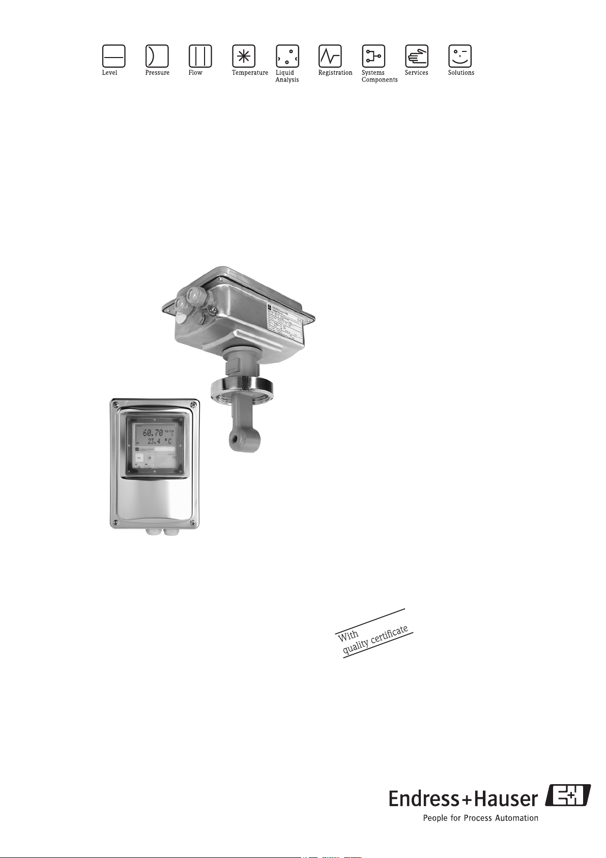
Smartec S CLD132
Measuring system with inductive sensor for conductivity and
concentration measurement in the food industry
6 8
Application
• Product monitoring in breweries, dairies and the beverage
industry
• CIP system control
• Phase separation of product/water and product/product
mixtures in pipe systems
• Alkali and acid concentration control in remaking
• Monitoring and control of bottle cleaning systems
Your benefits
• Transmitter housing made of stainless steel
• Sensor made of highly resistant plastic (PEEK)
• Sterilisable sensor
• High measuring reliability due to extensive self-monitoring
functions
• Insensitive to polarisation and soiling
• Versions with ultrafast temperature response (t
available
• Sensor versions for all process connections used in hygienic
applications
• Various operating possibilities:
– Keys
–HART
–PROFIBUS PA/DP
– PC with Commuwin II software
• Large two-line display allows simultaneous display of
measured value and temperature
• Standard version extendable by function extension with
remote parameter set switching (measuring range switching)
®
hand-held terminal
90
<5s)
TI207C/07/en/08.04
51501593
Page 2
Function and system design
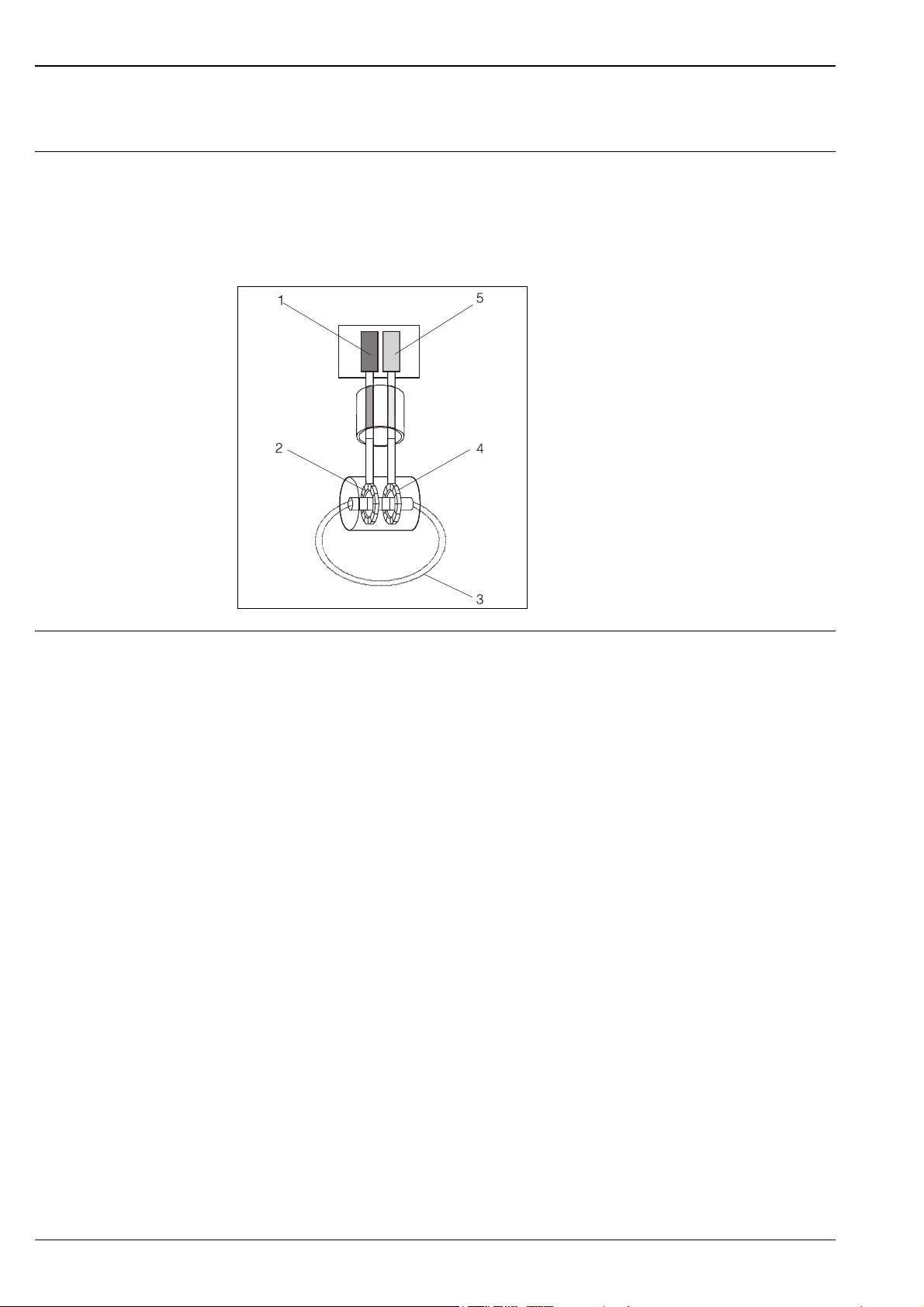
Measuring principle Inductive conductivity measurement
A generator (1) generates an alternating magnetic field in the primary coil (2) which induces a current in the
medium (3). The strength of the induced current depends on the conductivity and thus the ion concentration
of the medium. The current flow in the medium generates another magnetic field in the secondary coil (4).
The resulting current induced in the coil is measured by the receiver (5) and processed to determine the
conductivity.
Smartec S CLD132
Inductive conductivity measurement
1
Generator
2
Primary coil
3
Current flow in the medium
4
Secondary coil
5
Receiver
Benefits of inductive conductivity measurement
• No electrodes, therefore no polarisation
• Accurate measurement in media or solutions with
a high soiling degree and a tendency to deposition
• Complete galvanic separation of measurement and
medium
Important properties of
Smartec S CLD132
C07-CLXixxxx-15-0x-00-xx-001.eps
• Hygiene
The sensor, injection-moulded from highly chemically, mechanically and thermally resistant PEEK
(polyether ether keton), does not have joints or crevices and is therefore hygienically safe.
• Temperature measurement
– For applications requiring quick temperature measurement (e.g. CIP return, phase separation at various
temperatures), the Pt 100 temperature sensor is installed in a stainless-steel thermal conductivity socket
that is sealed by a Chemraz O-ring. This ensures extremely fast temperature response times (t
< 5 s).
90
– For high-load applications, particularly for alternating thermal load due to very frequent sterilisation cycles
or temperature shocks, the Pt 100 temperature sensor is embedded in the PEEK sensor body thus
eliminating the need for a seal. This ensures a long service life.
This sensor version can also be applied at underpressure.
• Temperature compensation
Smartec S CLD132 offers the following types of temperature compensation:
– Linear compensation with freely selectable temperature coefficient α
– Compensation according to IEC 746-3 for NaCl
– Compensation with freely programmable coefficient table with 10 elements maximum
• Process temperature
The use of special components and materials makes the sensor suitable for continuous exposure to
temperatures of +125 °C. Short-time (max. 30 min.), it will work at +140 °C for sterilisation.
• Concentration measurement
The transmitter can be switched from conductivity operating mode to concentration operating mode. The
concentration operating mode provides one freely programmable as well as various predefined concentration
curves, especially for common CIP solutions. This enables a direct display of the concentration in %.
• Remote parameter set switching
Smartec S CLD132 can be ordered with remote parameter set switching (measuring range switching, MRS)
enabling you
– to cover a wide measuring range
– to adjust temperature compensation when changing the product
– to switch between concentration curves.
2 Endress+Hauser
Page 3
Smartec S CLD132
ENDRESS+HAUSER
SMARTEC S
ALARM
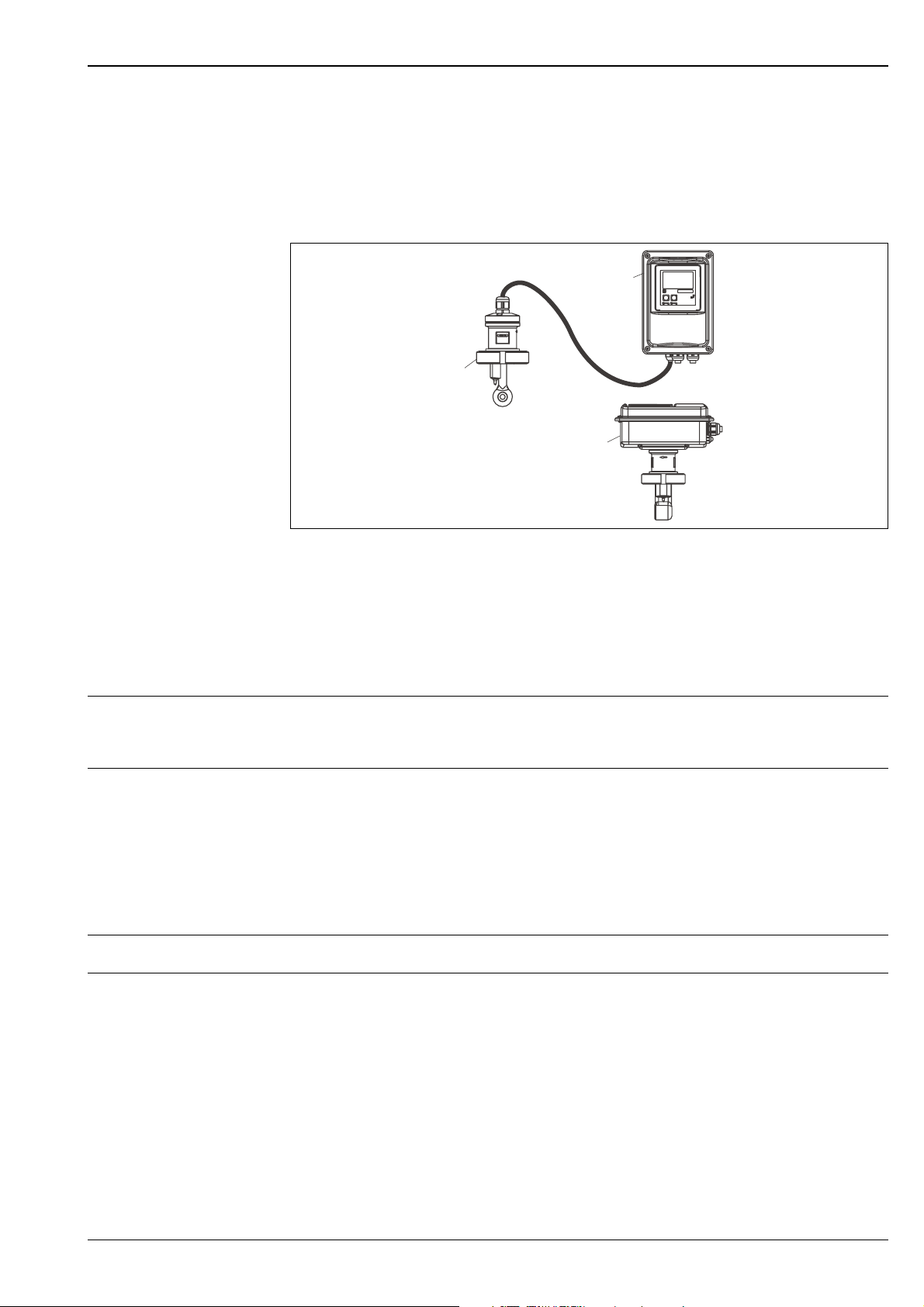
Measuring system A complete measuring system comprises:
• the Smartec S CLD132 transmitter
• the CLS52 conductivity sensor with integrated temperature sensor and fixed cable
or
• the CLD132 compact version with integrated CLS52 conductivity sensor
Optional for the separate version: CLK5 extension cable, VBM junction box, mounting kit for pipe mounting
A
B
ENDRESS+HAUSER
SMARTEC S
ALARM
CAL
+
E
–
C
Complete measuring systems Smartec S CLD132 as separate transmitter and compact version
A CLS52 conductivity sensor
B Smartec S CLD132 transmitter
C Smartec S CLD132 compact version with integrated CLS52
Input
Measured variables Conductivity
Concentration
Temperature
Measuring range
Sensor cable max. cable length 55 m / 180.46 ft with CLK5 cable (separate version)
Conductivity: recommended range: 100 µS/cm ... 2000 mS/cm (uncompensated)
Concentration:
NaOH: 0 ... 15 %
: 0 ... 25 %
HNO
3
H
: 0 ... 30 %
2SO4
H3PO4: 0 ... 15 %
User 1 (... 4): (4 tables available in versions with remote parameter set switching)
Temperature: –35 ... +250 °C / -31 ... +482 °F
C07-CLD132xx-14 -06-00-xx-001.EPS
Binary inputs 1 and 2
Voltage: 10 ... 50 V DC
Current consumption: max. 10 mA at 50 V
Endress+Hauser 3
Page 4

Output
Smartec S CLD132
Output signal
Signal on alarm 2.4 mA or 22 mA error current
Load max. 500 Ω
Output range
Signal resolution max. 700 digits/mA
Separation voltage max. 350 V
Minimum distance of
output signal
Conductivity: 0 / 4 ... 20 mA, galvanically isolated
Temperature (optional second current output)
Conductivity: adjustable
Temperature: adjustable
/ 500 V DC
RMS
Conductivity:
Measured value 0 ... 19.99 µS/cm: 2 µS/cm
Measured value 20 ... 199.9 µS/cm: 20 µS/cm
Measured value 200 ... 1999 µS/cm: 200 µS/cm
Measured value 0 ... 19.99 mS/cm: 2 mS/cm
Measured value 20 ... 200 mS/cm: 20 mS/cm
Measured value 200 ... 2000 mS/cm: 200 mS/cm
Concentration: no minimum distance
Temperature: 15 °C / 59 °F
Overvoltage protection acc. to EN 61000-4-5:1995
Auxiliary voltage output
Contact outputs
Limit contactor
Alarm
Output voltage: 15 V ± 0.6 V
Output current: max. 10 mA
Switching current with ohmic load (cos ϕ = 1): max. 2 A
Switching current with inductive load (cos ϕ = 0.4): max. 2 A
Switching voltage: max. 250 V AC, 30 V DC
Switching power with ohmic load (cos ϕ = 1): max. 500 VA AC, 60 W DC
Switching power with inductive load (cos ϕ = 0.4): max. 500 VA AC
Pickup / dropout delay: 0 ... 2000 s
(versions with remote parameter set switching only)
Function (switchable): steady / fleeting contact
Alarm delay: 0 ... 2000 s (min)
4 Endress+Hauser
Page 5
Smartec S CLD132
Electrical connection
Power supply
31
mA
A
B
C
D
10-50 V
E
10-50 V
32
85
86
93
94
81
82
33
34
Lf
optional
mA
15 V
84
15
16
83
S
11
12
13
41
42
43
∼
–
∼
–
PE
F
G
H
I
Sensor connection
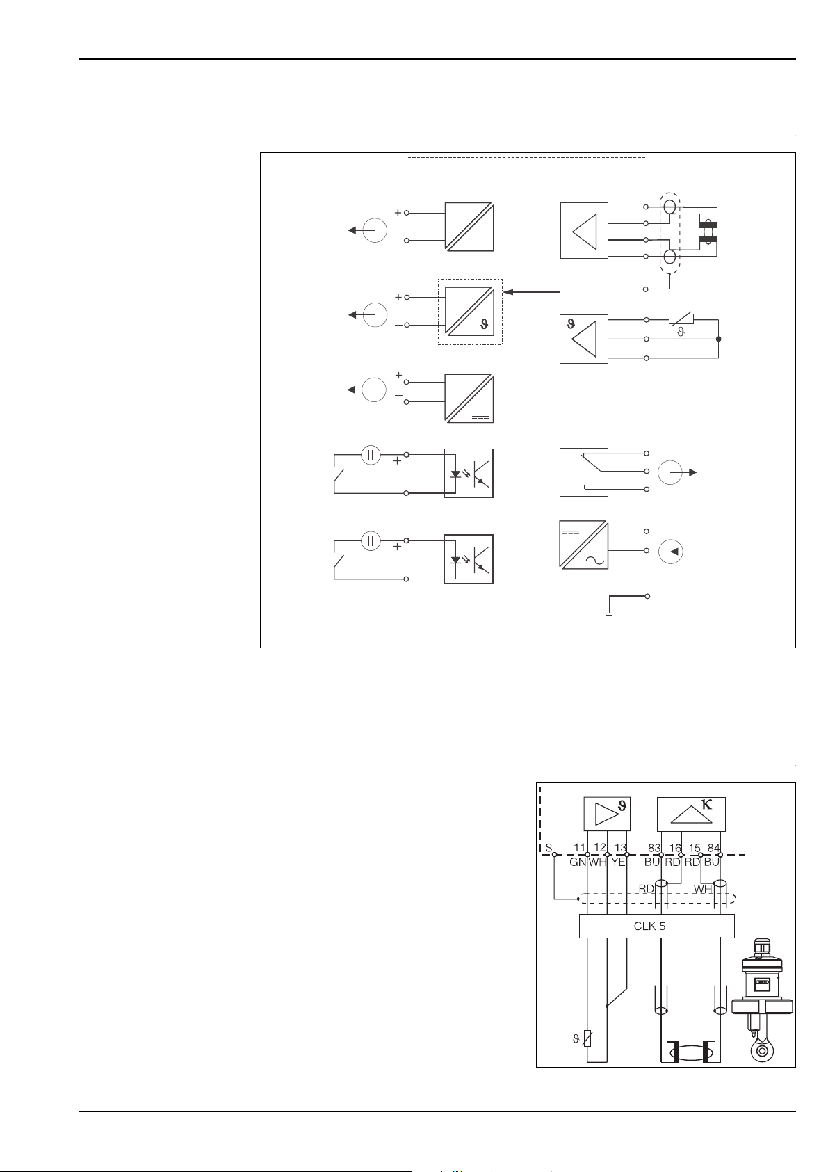
Electrical connection of CLD132
Signal output 1 conductivity
A
Signal output 2 temperature
B
Auxiliary power output
C
Binary input 2 (MRS 1+2)
D
Binary input 1 (hold / MRS 3+4)
E
The conductivity sensor of the separate version is
connected using the shielded multi-core fixed cable.
Use the junction box VBM and the CLK5 extension
cable (see Accessories) to extend the cable length.
C07-CLD132xx-05-06-00-xx-003.EPS
Conductivity sensor
F
Temperature sensor
G
Alarm (contact position: no current)
H
Power supply
I
Remote parameter set switching (measuring range
MRS:
switching)
Electrical connection of CLS52
C07-CLD132xx-05-06 -00-xx-006.EPS
Endress+Hauser 5
Page 6
Supply voltage Depending on ordered version:
100 / 115 / 230 V AC +10 / -15 %, 48 ... 62 Hz
24 V AC/DC +20 / -15 %
Smartec S CLD132
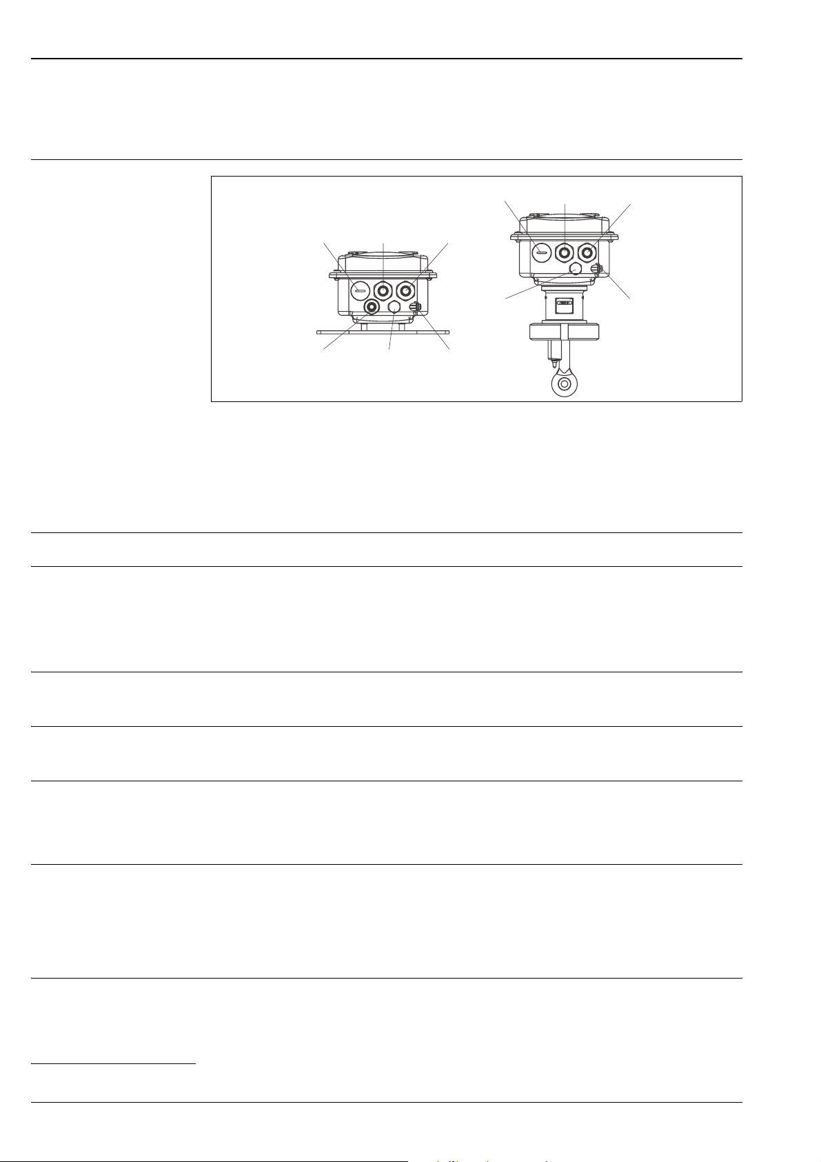
Cable entries
Terminal assignments of cable glands on Smartec S CLD132
A Separate version B Compact version
Plug, analog output, binary input
1
Cable gland for alarm contact
2
Cable gland for power supply
3
Housing ground
4
Pressure comp. element PCE (Goretex
5
6
Cable gland for sensor connection, Pg 9
Power consumption max. 7.5 VA
A
®
filter)
3
4
1
6
2
5
12
5
Plug, analog output, binary input
1
Cable gland for alarm contact
2
Cable gland for power supply
3
Housing ground
4
Pressure comp. element PCE (Goretex
5
B
3
4
C07-CLD132xx-04-06 -04-xx-001.eps
®
filter)
Mains fuse Fine-wire fuse, medium time lag, 250 V / 3.15 A
Performance characteristics
Measured value resolution
Temperature response time
Measured error of the sensor
Measured error of the transmitter
a
Temperature: 0.1 °C / 0.18 °F
< 5 s versions with stainless steel socket (CLD132-********1/2)
t
90
t90 < 3.5 min versions with encapsulated Pt 100 (CLD132-********6/7)
a
Conductivity:
– -5 ... +100 °C / 23 ... 212 °F
– > 100 °C / > 212 °F
± (10 µS/cm + 0.5 % of measured value)
± (30 µS/cm + 0.5 % of measured value)
Temperature: Pt 100 class A acc. to IEC 751
Conductivity:
– Display:
– Conductivity signal output:
max. 0.5 % of measured value ± 4 digits
max. 0.75 % of current output range
Temperature
– Display:
– Temperature signal output:
max. 0.6 % of measuring range
max. 0.75 % of current output range
Repeatability
a) acc. to IEC 60746 part 1, at nominal operating conditions
a
Conductivity: max. 0.2% of measured value ± 2 digits
6 Endress+Hauser
Page 7
Smartec S CLD132
Cell constant 5.9 cm
Measuring frequency
-1
2 kHz
(oscillator)
Temperature compensation
Range: –10 ... +150 °C / 14 ... 302 °F
Compensation types: – none
– linear with freely selectable temperature coefficient α
– one freely programmable coefficient table (four tables available
in versions with remote parameter set switching)
– NaCl acc. to IEC 746-3
Minimum distance for table: 1 K
Reference temperature 25 °C / 77 °F
Temperature offset adjustable, ± 5 °C / 9 °F, for temperature display adjustment
Installation
Installation instructions
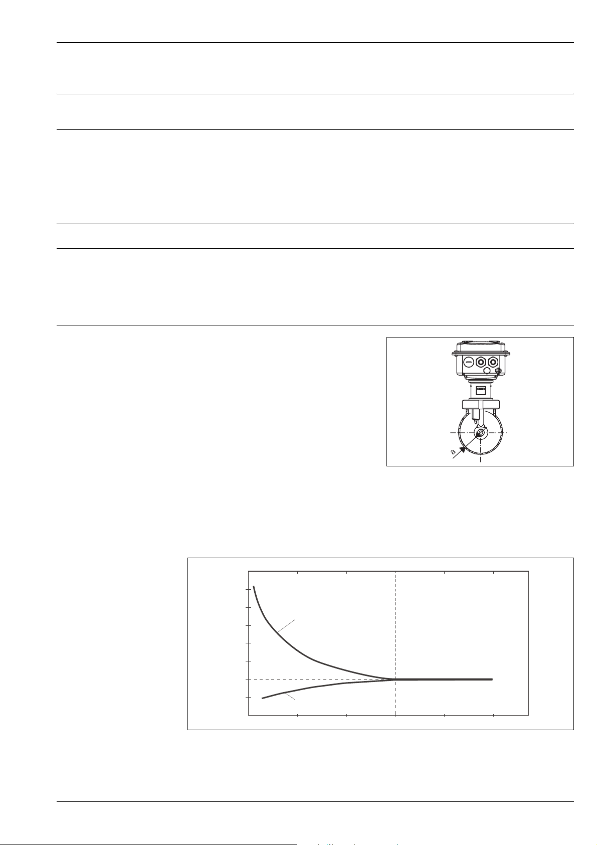
In narrow installation conditions, the ion flow in the
medium is affected by the pipe walls. This effect is
compensated by the so-called installation factor. The
installation factor can be entered in the transmitter or
the cell constant can be corrected by multiplication
with the installation factor to ensure correct
measurement.
The value of the installation factor depends on the
diameter and the conductivity of the pipe as well as
the sensor’s distance from the wall.
If the distance from the wall is sufficient (a > 15 mm,
from DN 65), it is not necessary to consider the
installation factor (f = 1.00).
If the distance from the wall is smaller, the installation
factor increases in case of electrically insulating pipes
(f > 1) and decreases in case of electrically conductive
pipes (f < 1).
The installation factor can be measured using
calibration solutions or it can be approximately
determined from the diagram below.
f
0.20
0.39
CLD132 installation
a Wall distance
0.59
0.79
0.98
a [inch]
C07-CLD132xx-11-06 -00-xx-009.eps
1,40
2
1,20
1,00
1
0,80
0
Relationship between installation factor f and distance from wall a
1 Electrically conductive pipe wall
2 Insulating pipe wall
5
10 15
20
a [mm]
2525
C07-CLD132xx-05 -06-00-de-001.eps
Endress+Hauser 7
Page 8
Smartec S CLD132
Air set To compensate residual coupling in the cable and between the two sensor coils, you must perform a zero
calibration in air ("air set") before installing the sensor.
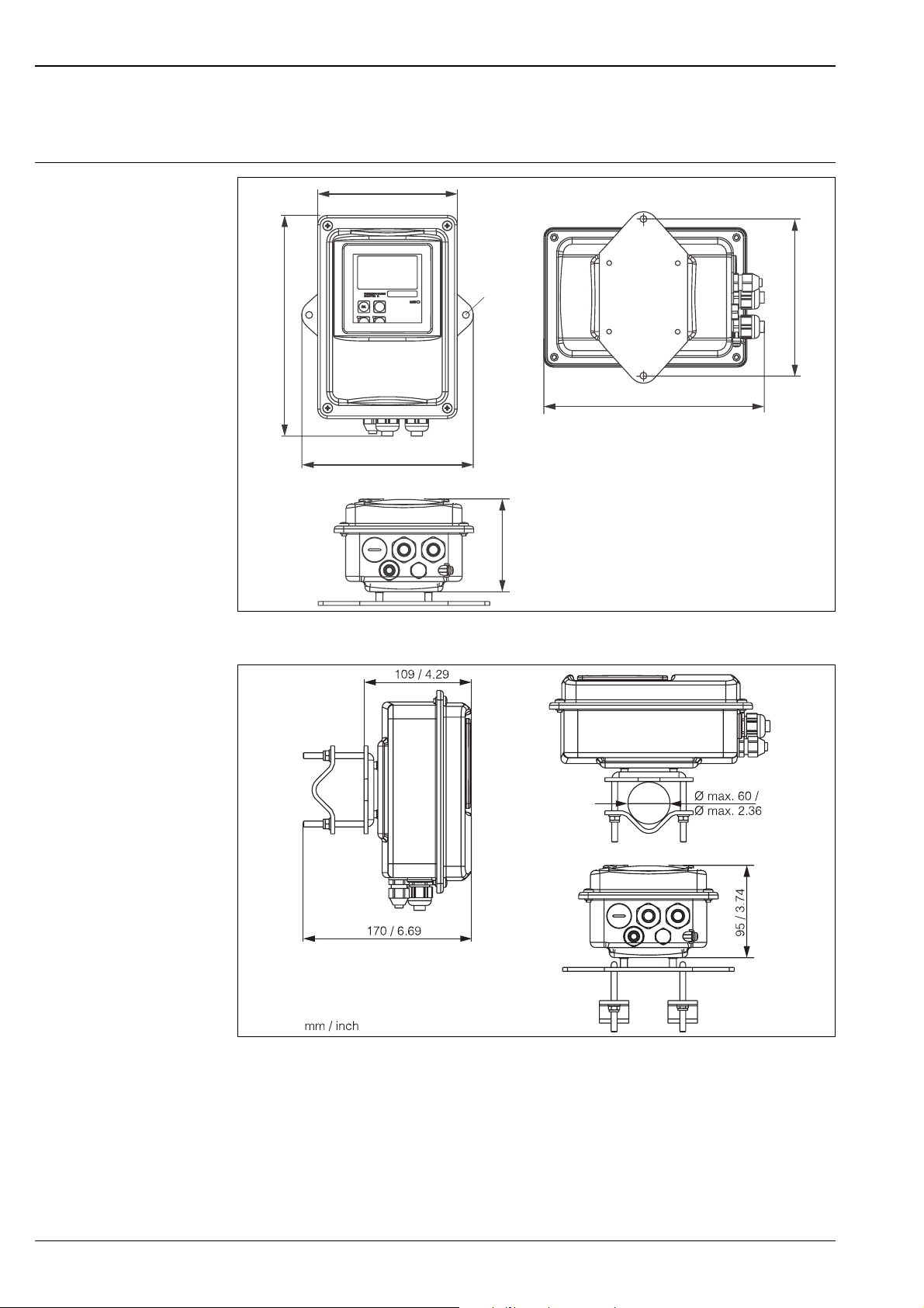
Mounting CLD132 separate version
225 / 8.86
CLD132 wall mounting
142 / 5.59
175 / 6.89
Ø 7 / 0.28
95 / 3.74
225 / 8.86
160 / 6.30
mm /inch
C07-CLD132xx-11 -06-00-en-001.eps
CLD132 mounting on pipes (Ø 60 mm / 2.36") using the pipe mounting kit (see Accessories)
C07-CLD132xx-11 -06-00-en-002.eps
8 Endress+Hauser
Page 9
Smartec S CLD132
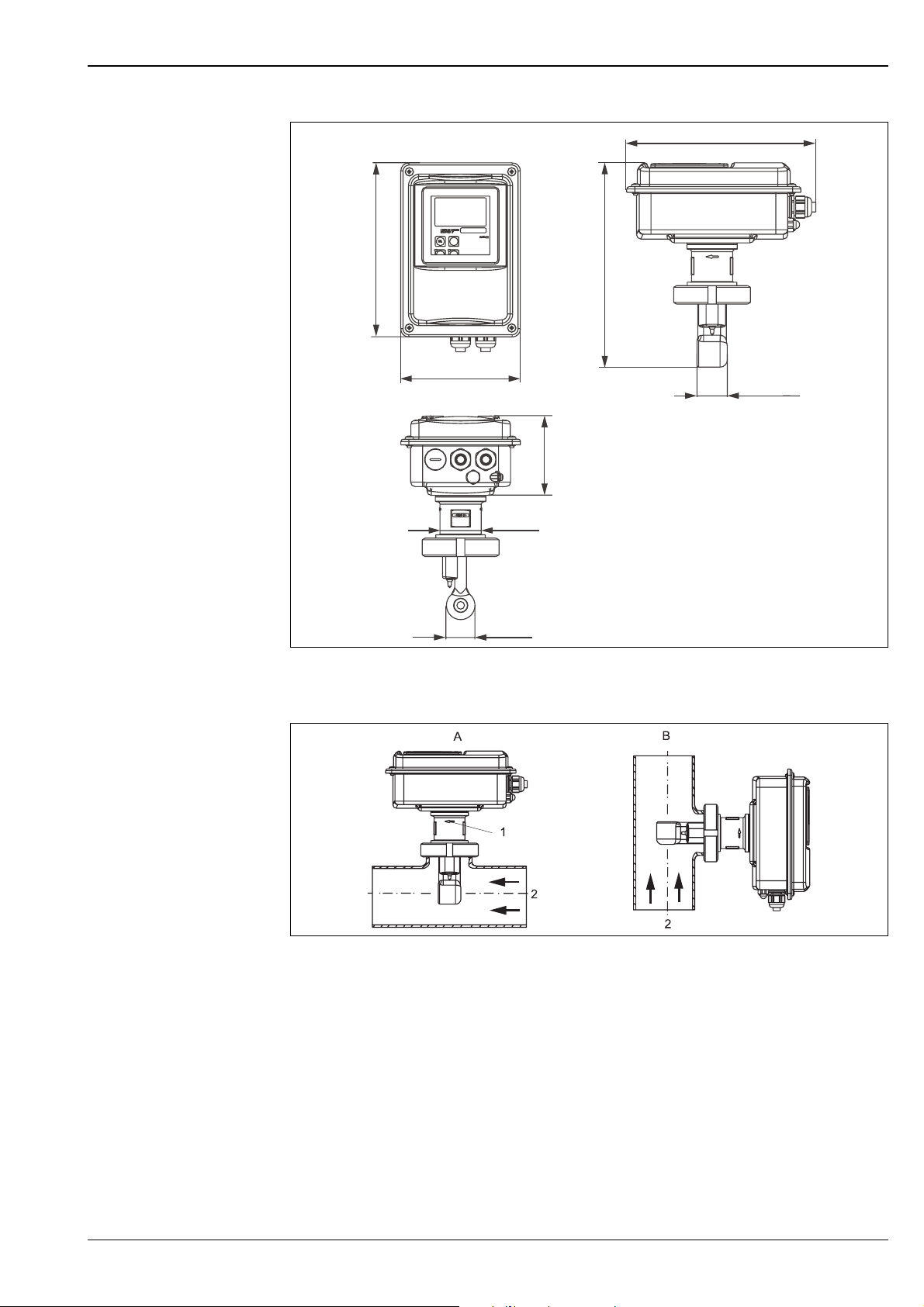
Mounting CLD132 compact version
225 / 8.86
207 / 8.15
242 (180)* / 9.53 ( 7.09)*
142 / 5.59
35.5 / 1.40
95 / 3.74
∅ 49 / 1.93
!
34 / 1.34
Dimensions of CLD132 compact version
* depending on ordered process connection
Orientation of CLD132 compact version
A Horizontal flow
BVertical flow
1 Orientation arrow
2 Flow direction
mm / inch
C07-CLD132xx-11-06 -00-en-004.eps
C07-CLD132xx-11-06-00-xx-006.eps
Note!
The housing can be rotated against the sensor to allow comfortable viewing of the display in any mounting
position.
Endress+Hauser 9
Page 10

Environment
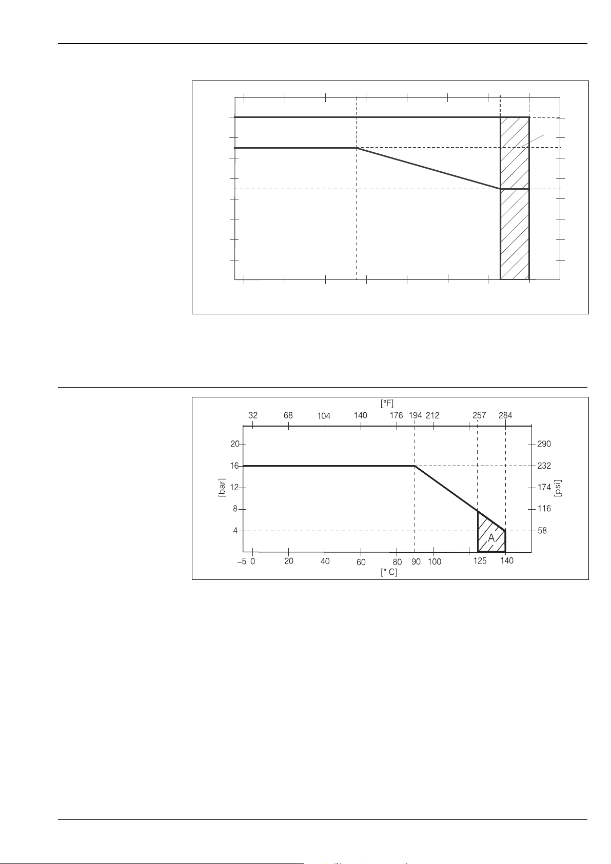
Ambient temperature 0 ... +55 °C / 32 ... 131 °F
Ambient temperature limits –10 ... +70 °C / 14 ... 158 °F (separate version)
–10 ... +55 °C / 14 ... 131 °F (compact version)
See figure "Permissible temperature ranges of Smartec S CLD132" on page 11.
Storage temperature –25 ... +70 °C / -13 ... 158 °F
Electromagnetic compatibility Interference emission and interference resistance acc. to EN 61326: 1997 / A1: 1998
Ingress protection IP 67
Relative humidity 10 ... 95%, non-condensing
Smartec S CLD132
Vibration resistance acc. to
IEC 60770-1 and IEC 61298-3
Impact resistance
Oscillation frequency: 10 ... 500 Hz
Deflection (peak value): 0.15 mm / 0.01"
Acceleration (peak value): 19.6 m/s
Display window: 9 J
Process
Process temperature
Sterilisation
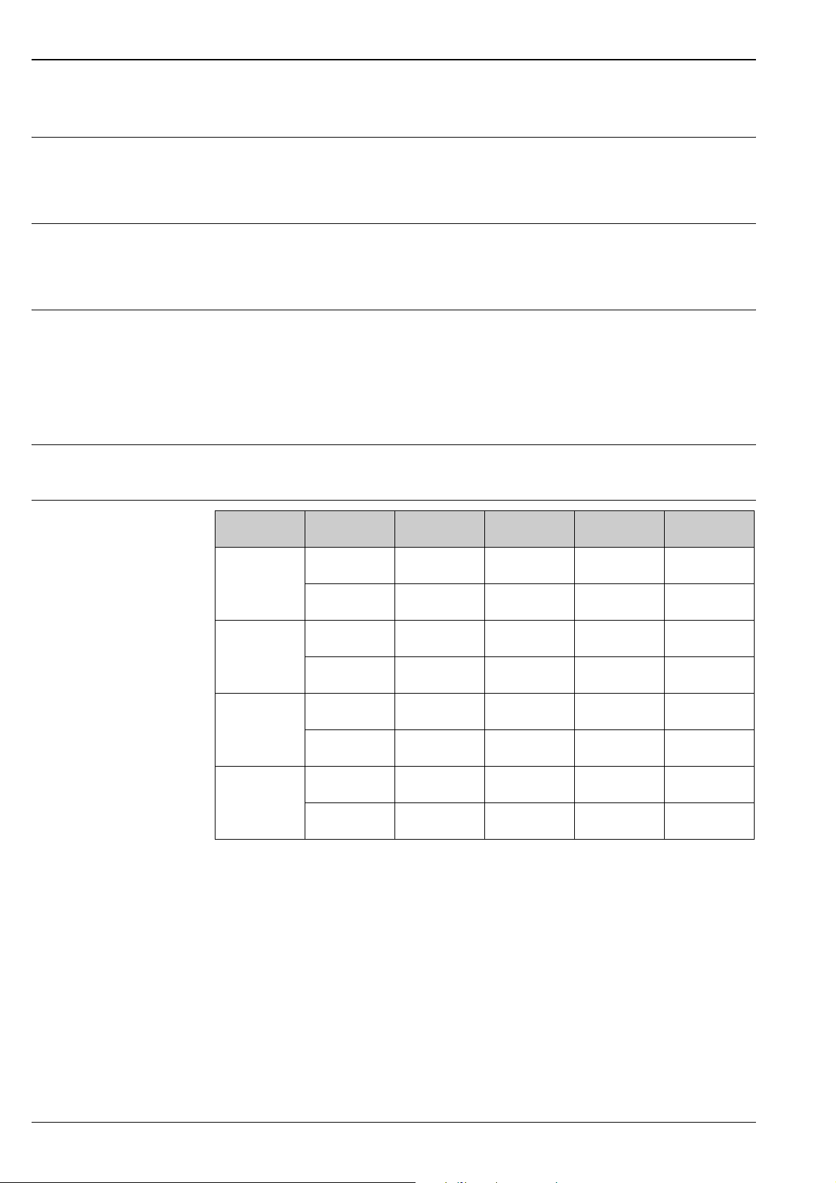
Process pressure max. 16 bar (90 °C) / 232 psi (194 °F)
CLS52 sensor with separate version: max. 125 °C / 257 °F at 70 °C / 158 °F ambient temperature
Compact version: max. 125 °C / 257 °F at 35 °C / 95 °F ambient temperature
CLS52 sensor with separate version: 140 °C / 284 °F at 70 °C / 158 °F ambient temperature, 4 bar / 58 psi,
Compact version: 140 °C / 284 °F at 35 °C / 95 °F ambient temperature, 4 bar / 58 psi,
no underpressure allowed with versions with stainless steel socket (CLD132********1, CLD132********2)
2
max. 55 °C / 131 °F at 55 °C / 131 °F ambient temperature
max. 30 min
max. 30 min
10 Endress+Hauser
Page 11
Smartec S CLD132
Permissible temperature ranges of Smartec S CLD132
32
68
104 140 176
131
[° C]
70
60
55
B
50
40
35
30
20
Ambient temperature
10
0
–10
–5
0
20
40
55
Permissible temperature ranges of Smartec S CLD132
A CLS52 sensor with separate version
B Compact version
C Short-term for sterilisation (< 30 min)
A
60
80
Medium temperature
212
100
248
120
257
125
284
[°F]
[°F]
158
C
140
131
122
104
95
86
68
50
32
140
[° C]
C07-CLD132xx-05-06 -00-en-013.eps
Pressure-temperature load curve of CLS52 sensor
Permissible pressure and temperature ranges of CLS52 sensor
C07-CLS52xxx-05-05 -00-en-001.eps
A short-term for sterilisation (< 30 min)
Endress+Hauser 11
Page 12
Mechanical construction
Smartec S CLD132
Dimensions
Weight
Materials of the sensor (in contact with medium)
Materials of the transmitter
Chemical durability of the
sensor
Separate transmitter with mounting plate: L x W x D: 225 x 142 x 109 mm / 8.86 x 5.59 x 4.29"
Compact transmitter
MV1, CS1, GE1, SMS versions: L x W x D: 225 x 142 x 242 mm / 8.86 x 5.59 x 9.53"
VA1, AP1 versions: L x W x D: 225 x 142 x 180 mm / 8.86 x 5.59 x 7.09"
Separate version:
Transmitter: approx. 2.5 kg / 5.5 lb.
CLS52 sensor depending on version , approx. 400 ... 800 g / 0.9 ... 1.8 lb.
Compact version with CLS52 sensor: approx. 3 kg / 6.6 lb.
Sensor PEEK-GF20
Varivent flange, APF flange:
Flange: stainless steel 1.4435 (AISI 316L
)
Seal: EPDM
Metall temperature sensor socket:
Socket: stainless steel 1.4435 (AISI 316L)
Seal: Chemraz
®
Housing: stainless steel 1.4301
Front window: polycarbonate
Medium Concentration PEEK 1.4435
(AISI 316L)
Caustic soda
NaOH
Nitric acid
HNO
3
Phosphoric acid
H
3PO4
Sulphuric acid
H
2SO4
0 ... 10 %
0 ... 50 %
0 ... 10 %
0 ... 25 %
0 ... 10 %
0 ... 30 %
0 ... 2.5 %
0 ... 30 %
20 ... 100 °C /
68 ... 212 °F
20 ... 100 °C /
68 ... 212 °F
20 ... 100 °C /
68 ... 212 °F
20 ... 40 °C /
68 ... 104 °F
20 ... 100 °C /
68 ... 212 °F
20 ... 100 °C /
68 ... 212 °F
20 ... 100 °C /
68 ... 212 °F
20 ... 100 °C /
68 ... 212 °F
1
1
20 ... 90 °C /
68 ... 194 °F
20 ... 90 °C /
68 ... 194 °F
20 ... 100 °C /
68 ... 212 °F
20 ... 100 °C /
68 ... 212 °F
20 ... 100 °C /
68 ... 212 °F
20 ... 85 °C /
68 ... 185 °F
20 ... 70 °C /
68 ... 158 °F
not suitable
Chemraz EPDM
20 ... 100 °C /
68 ... 212 °F
20 ... 100 °C /
68 ... 212 °F
20 ... 100 °C /
68 ... 212 °F
20 ... 100 °C /
68 ... 212 °F
20 ... 100 °C /
68 ... 212 °F
20 ... 100 °C /
68 ... 212 °F
20 ... 100 °C /
68 ... 212 °F
20 ... 100 °C /
68 ... 212 °F
1
1
20 ... 100 °C /
68 ... 212 °F
20 ... 60 °C /
68 ... 140 °F
20 °C / 68 °F
not suitable
20 ... 80 °C /
68 ... 176 °F
20 ... 80 °C /
68 ... 176 °F
20 ... 30 °C /
68 ... 86 °F
20 ... 30 °C /
68 ... 86 °F
1) slight affect possible
No responsibility is taken for the correctness of this information.
12 Endress+Hauser
Page 13
Smartec S CLD132
Process connections
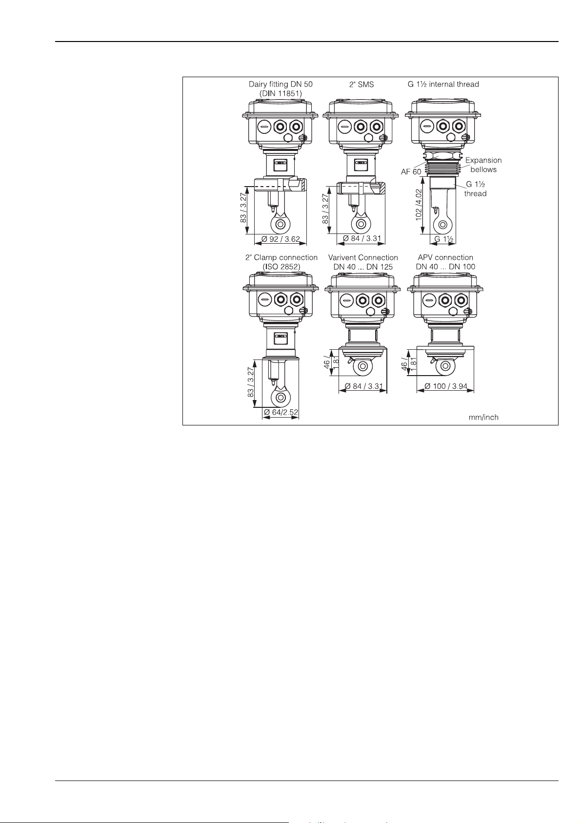
Process connections of CLD132 compact version
C07-CLD132xx-11-06 -00-en-005.eps
Endress+Hauser 13
Page 14
Smartec S CLD132
!
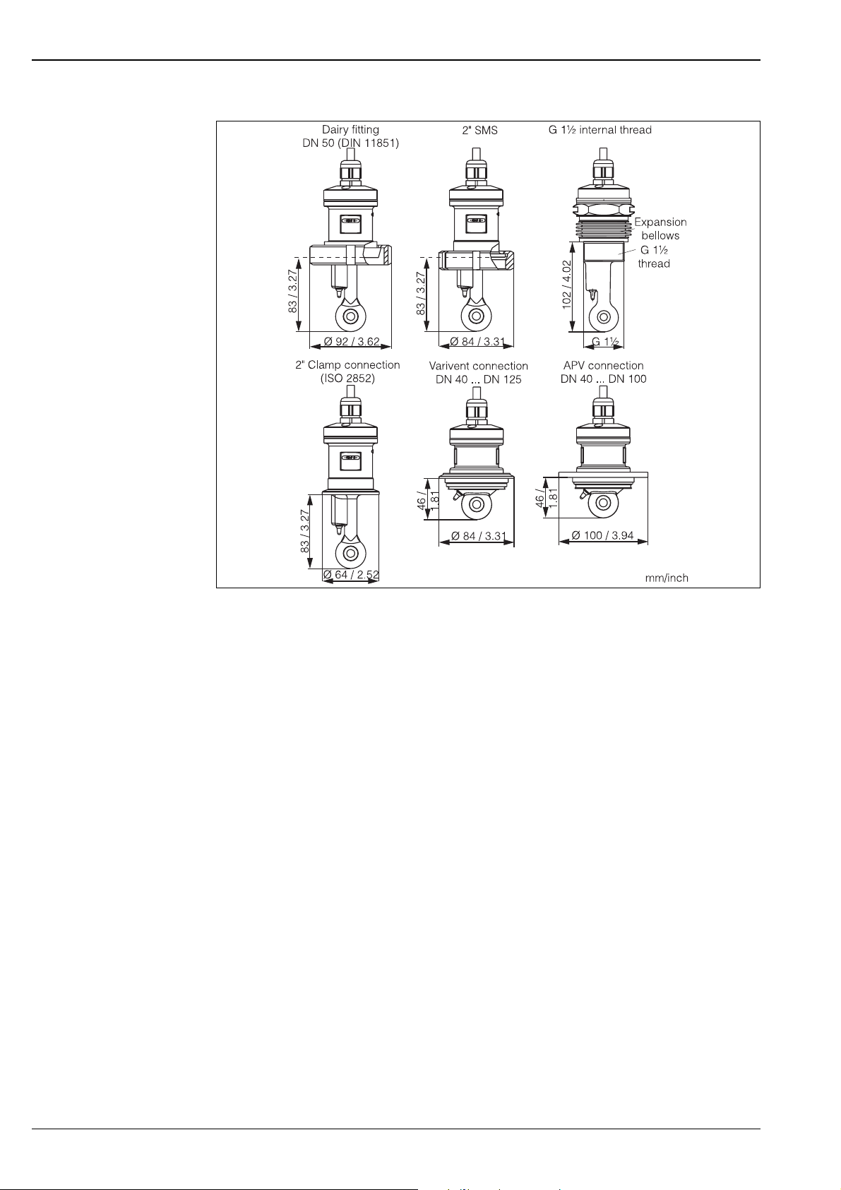
Process connections of CLS52 conductivity sensor
C07-CLD132xx-11 -06-00-en-003.eps
Note!
• Clamp connection
Sensors with clamp connections can be fixed using sheet metal brackets or solid brackets.
Sheet metal brackets have a lower dimensional stability, uneven bearing surfaces causing point loads and
sometimes sharp edges that can damage the clamp.
We strongly recommend to always use solid brackets because of their higher dimensional stability. Solid
brackets may be applied over the total pressure-temperature range (see diagram on page 11).
• Threaded connection
Sensors with threaded connections are supplied with expansion bellows (compensator) to be able to align
them in flow direction. The two O-rings (Viton) of the expansion bellows have no sealing function and are
not in contact with medium. The process is usually sealed off by PTFE tape on the G 1½ thread.
14 Endress+Hauser
Page 15
Smartec S CLD132
Display and operating elements
Human interface
1
2000
mS/cm
O213
20 mA
ENDRESS+HAUSER
SMARTEC S
CAL
+
E
–
2
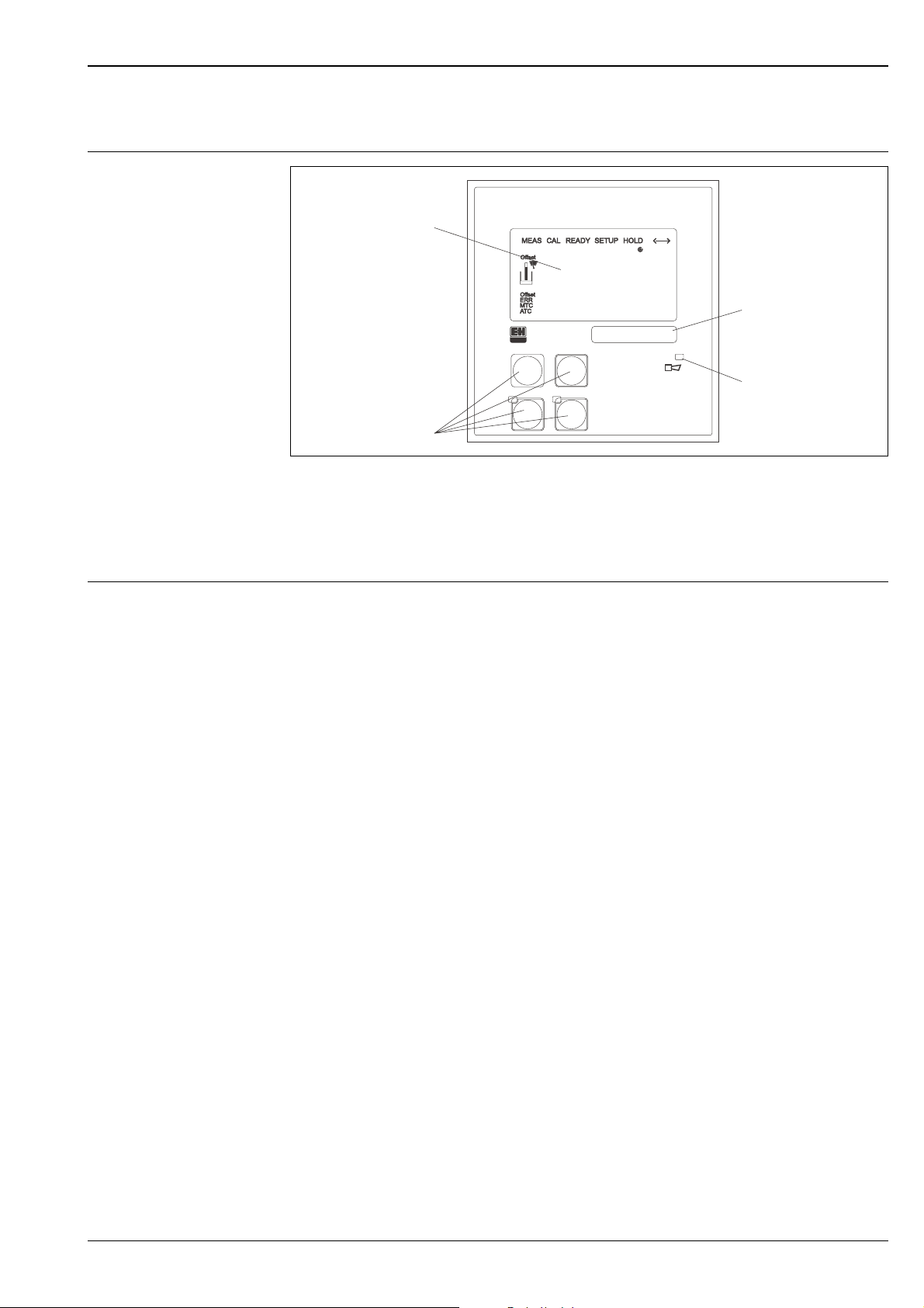
Display and keys of CLD132
1 LC display showing measured values and configuration data
2 Four operating keys for calibration and instrument configuration
3 Field for user labeling
4 LED indicator for alarm function
Operation You have the following options of operating Smartec S CLD132:
• Local operation via operating keys
The four keys are located underneath the housing cover. For operation, open the housing cover by removing
the four screws.
•Via HART® interface
– HART hand-held terminal
– PC with HART modem and the Communwin II software
• Via PROFIBUS PA/DP using a PC with a corresponding interface and the Communwin II software or via
programmable logical controller (PLC)
3
ALARM
4
C07-CLD132xx-19-06-00-xx-001.eps
Endress+Hauser 15
Page 16
Smartec S CLD132
Calibration and configuration functions
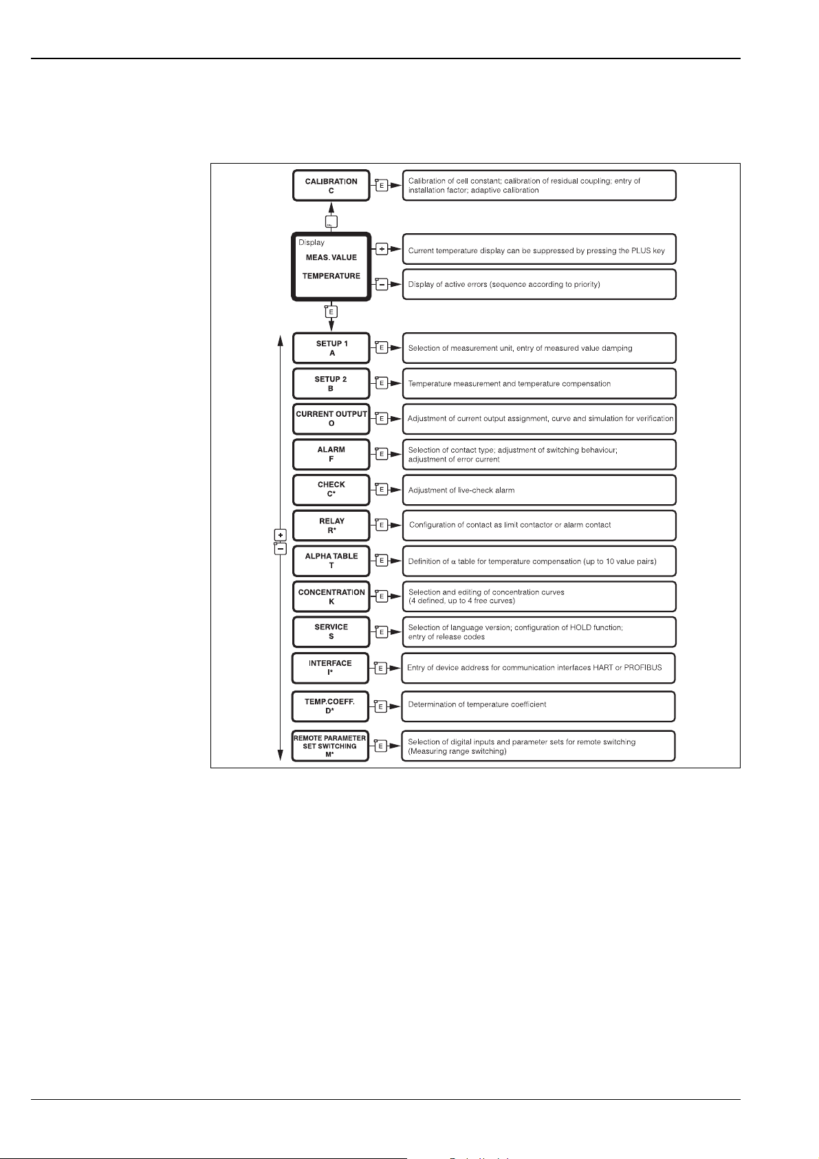
All calibration and configuration functions are arranged in a logical menu structure. The individual parameters
can only be modified after entering the access code. The current position within the menu structure is
displayed.
Overview of the Smartec S CLD132 menu, showing all options that can be installed
* Menus not available in standard version
C07-CLD132xx-19 -06-00-en-001.eps
16 Endress+Hauser
Page 17
Smartec S CLD132
Ordering information
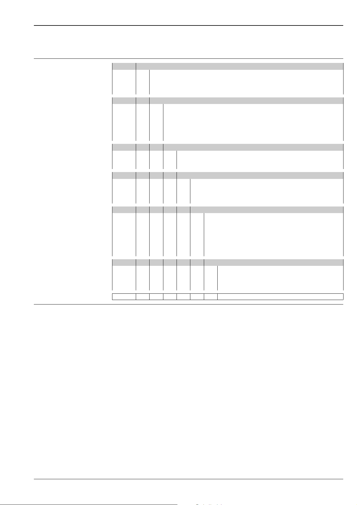
Product structure
Version
P Compact version
S Separate transmitter, cable length 20 m / 65.62 ft
W Separate transmitter, cable length 5 m / 16.41 ft
X Separate transmitter, cable length 10 m / 32.81 ft
Process connection
MV1 Dairy fitting DN 50 (acc. to DIN 11851)
CS1 Clamp connection 2" (acc. to ISO 2852)
GE1 Internal thread G 1 ½
VA1 Varivent connection DN 40 ... 125
AP1 APV connection DN 40 ... 100
SMS SMS connection 2"
Cable entry
1 Cable gland Pg 13.5
3 Cable gland M 20 x 1.5
5 Conduit adapter NPT ½ "
Power supply
0 230 V AC
1 115 V AC
5 100 V AC
824 V AC / DC
Current output / communication
AA Current output conductivity, without communication
AB Current output conductivity and temperature, without communication
HA HART, current output conductivity
HB HART, current output conductivity and temperature
PE PROFIBUS-PA, no current output
PF PROFIBUS-PA, M 12 connector, no current output
PP PROFIBUS-DP, no current output
Additional features
1 Basic version with fast temperature measurement
2 Remote parameter set switching with fast temperature measurement
6 Basic version with encapsulated Pt 100 for high loads
7 Remote parameter set switching with encapsulated Pt 100 for high loads
CLD132- complete order code
Scope of delivery The scope of delivery of the compact version inlcudes:
• Smartec S CLD132 compact measuring system with integrated sensor
• Terminal strip set
• Expansion bellows (-*GE1***** versions only)
• Operating Instructions BA 207C/07/en
• Versions with HART communication only:
Operating Instructions Field communication with HART, BA 212C/07/en
• Versions with PROFIBUS interface only:
– Operating Instructions Field communication with PROFIBUS, BA 213C/07/en
– M12 connector (-******PF* versions only)
The scope of delivery of the separate version includes:
• Smartec S CLD132 transmitter
• CLS52 inductive sensor with fixed cable
• Terminal strip set
• Expansion bellows (-*GE1***** versions only)
• Operating Instructions BA 207C/07/en
• Versions with HART communication only:
Operating Instructions Field communication with HART, BA 212C/07/en
• Versions with PROFIBUS interface only:
– Operating Instructions Field communication with PROFIBUS, BA 213C/07/en
– M12 connector (-******PF* versions only)
Endress+Hauser 17
Page 18
Smartec S CLD132
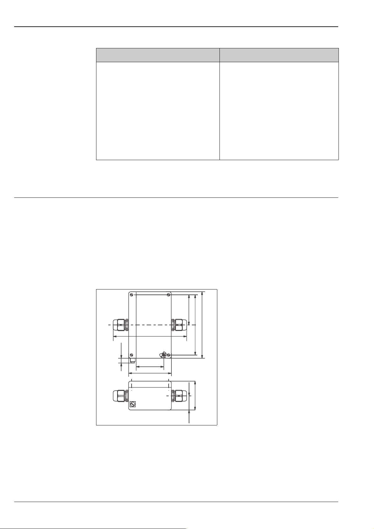
Basic version and function extensions
Functions of the basic version Options and their functions
•Measurement
• Calibration of cell constant
• Calibration of residual coupling
• Calibration of installation factor
• Read instrument parameters
• Linear current output
• Current output simulation
•Service functions
• Temperature compensation selectable (e.g. 1 free
coefficient table)
• Concentration measurement selectable (4 defined
curves, 1 free table)
• Relay as alarm contact
Accessories
Cable extension ❑ Extension cable CLK5
for inductive conductivity sensors, for extension via the VBM junction box, sold by the metre;
order no.: 50085473
❑ Junction box VBM
for extension of measuring cable connection between sensor and instrument, material cast aluminium,
ingress protection 65;
order no.: 50003987
Note!
!
The desiccant bag must be checked and replaced at regular intervals which depend on ambient conditions
in order to prevent inaccurate measurement due to moisture bridges in the measuring line.
• Second current output for temperature (hardware
option)
• HART communication
• PROFIBUS communication
Remote parameter set switching (software option):
• Remote switching of max. 4 parameter sets
(measuring ranges)
• Temperature coefficients can be determined
• Temperature compensation selectable (e.g. 4 free
coefficient tables)
• Concentration measurement selectable (4 defined
curves, 4 free tables)
• Check of measuring system by PCS alarm (live check)
• Relay can be configured as alarm or limit contact
62.5 / 2.46
113 / 4.45
55 / 2.17
1.06
26.8 /
125 / 4.92
approx.. 136 /
5.35
10 /
0.39
52 / 2.05
80 / 3.15
mm / inch
Dimensions of VBM junction box
C07-CLD132x-00-06 -00-en-002.eps
❑ Desiccant bag with colour indicator for VBM junction box;
order no. 50000671
18 Endress+Hauser
Page 19
Smartec S CLD132
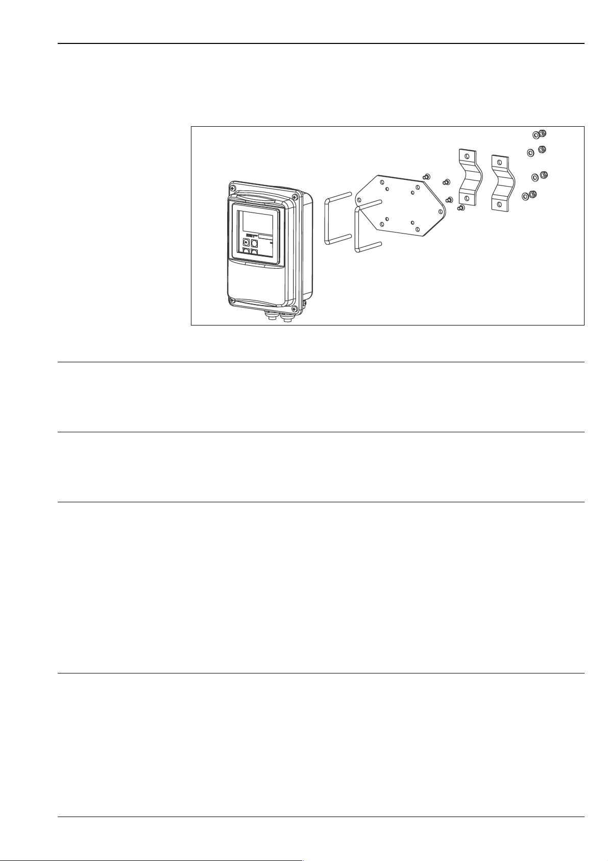
Pipe mounting kit ❑ Mounting kit for installation of Smartec S CLD132 on horizontal or vertical pipes and posts
(max. Ø 60 mm / 2.36"), material stainless steel 1.4301;
order no.: 50062121
Mounting kit for installing CLD132 separate version on posts or pipes
C07-CLD132xx-00-06 -06-001.eps
Software upgrade ❑ Software upgrade
Remote parameter set switching (measuring range switching, MRS) and determination of temperature
coefficient;
order no.: 51501643
Serial number of instrument must be specified with order.
Optoscope ❑ Optoscope
Interface between transmitter and PC / laptop for service purposes.
The Windows software "Scopeware" required for the PC or laptop is supplied with the Optoscope. The
Optoscope is supplied in a sturdy plastic case with all the accessories required.
Order no. 51500650
Calibration solutions Precision solutions, traceable to SRM (standard reference material) by NIST, for qualified calibration of
conductivity measurement systems according to ISO 9000, with temperature table
❑ CLY11-B
149.6 µS/cm (reference temperature 25 °C / 77 °F), 500 ml / 0.13 US.gal.
Order no. 50081903
❑ CLY11-C
1.406 mS/cm (reference temperature 25 °C / 77 °F), 500 ml / 0.13 US.gal.
Order no. 50081904
❑ CLY11-D
12.64 mS/cm (reference temperature 25 °C/ 77 °F), 500 ml / 0.13 US.gal.
Order no. 50081905
❑ CLY11-E
107.0 mS/cm (reference temperature 25 °C / 77 °F), 500 ml / 0.13 US.gal
Order no. 50081906
Related products ❑ Indumax H CLS52
Inductive conductivity sensor with fast response time and hygienic design;
with integrated temperature sensor.
Order according to product structure, see Technical Information TI 167C/07/en.
One Indumax H CLS52 is included in the Smartec S CLD132 scope of delivery.
Endress+Hauser 19
Page 20

Documentation
❑ Smartec S CLD132, Operating Instructions BA207C/07/en
Order no.: 51501595
❑ Indumax H CLS52, Technical Information TI 167C/07/en
Order no.: 50086110
❑ PROFIBUS PA/DP, Field communication with Smartec S CLD132, Operating Instructions
BA 213C/07/en
Order no.: 51502194
®
❑ HART
, Field communication with Smartec S CLD132, Operating Instructions BA 212C/07/en
Order no.: 51502192
International Head Quarters
Endress+Hauser
GmbH+Co. KG
Instruments International
Colmarer Str. 6
79576 Weil am Rhein
Deutschland
Tel. +49 76 21 9 75 02
Fax +49 76 21 9 75 34 5
www.endress.com
[email protected]
TI207C/07/en/08.04
51501593
Printed in Germany / FM+SGML 6.0 / DT
 Loading...