


FMR60
Table of contents
 Loading...
TI01302F/00/EN/04.18
71394723
2018-04-12
Products
Solutions Services
Technical Information
Micropilot FMR60
Free space radar
Level measurement in liquids
Application
• Continuous, non-contact level measurement of liquids,
pastes and sludges
• PTFE drip-off antenna
• Maximum measuring range: 50 m (164 ft)
• Temperature: –40 to +130 °C (–40 to +266 °F)
• Pressure: –1 to +16 bar (–14.5 to +232 psi)
• Accuracy: ± 1 mm (0.04 in)
• Linearity protocol (3-point, 5-point)
Your benefits
• Innovative drip-off antenna made of PTFE
• Reliable measurement thanks to improved focusing and small beam angle,
particularly in vessels with many internal fittings
• Safety by design - ensures highest safety
• Easy, guided commissioning with intuitive user interface
• Bluetooth® wireless technology for commissioning, operation and maintenance via
free iOS / Android app SmartBlue
• Maximum reliability thanks to multi-echo tracking
• HistoROM configuration memory makes for easier commissioning,
maintenance and diagnostics
• SIL2 as per IEC 61508, SIL3 for homogeneous or diverse redundancy
• Easy proof testing for SIL and WHG
• RFID TAG - easy identification of measuring points for improved data access
• Heartbeat Technology

Table of contents
Micropilot FMR60
Important document information ............... 4
Safety symbols ............................... 4
Electrical symbols ............................. 4
Symbols for certain types of information .............. 4
Symbols in graphics ............................ 4
Symbols at the device ........................... 5
Terms and abbreviations ..................... 6
Registered trademarks ....................... 7
Function and system design ................... 8
Measuring principle ............................ 8
Input ..................................... 9
Measured variable ............................. 9
Measuring range .............................. 9
Operating frequency .......................... 10
Transmission power ........................... 10
Output .................................. 11
Output signal ............................... 11
Signal on alarm .............................. 12
Linearization ............................... 12
Galvanic isolation ............................ 12
Protocol-specific data .......................... 12
Power supply ............................. 14
Terminal assignment .......................... 14
Device plug connectors ......................... 18
Supply voltage .............................. 19
Power consumption ........................... 20
Current consumption .......................... 20
Power supply failure .......................... 20
Potential equalization ......................... 20
Cable entries ............................... 21
Cable specification ............................ 21
Overvoltage protection ......................... 21
Performance characteristics .................. 22
Reference operating conditions ................... 22
Reference accuracy ........................... 22
Measured value resolution ...................... 22
Response time .............................. 22
Influence of ambient temperature ................. 23
Influence of gas phase ......................... 23
Climate class ............................... 31
Altitude according to IEC61010-1 Ed.3 .............. 31
Degree of protection .......................... 31
Vibration resistance ........................... 31
Electromagnetic compatibility (EMC) ............... 31
Process .................................. 32
Process temperature, process pressure ............... 32
Dielectric constant ............................ 33
Minimum level in case of small dielectric constants ...... 33
Mechanical construction .................... 34
Dimensions ................................ 34
Weight ................................... 37
Materials: GT19 housing (plastic) .................. 38
Materials: GT20 housing (die-cast aluminum, powder-
coated) ................................... 39
Materials: antenna and process connection ........... 40
Materials: Weather protection cover ................ 41
Operability ............................... 42
Operating concept ............................ 42
Local operation .............................. 43
Operation with remote display and operating module
FHX50 ................................... 43
Operation via Bluetooth® wireless technology .......... 44
Remote operation ............................ 45
SupplyCare inventory management software .......... 46
Certificates and approvals ................... 49
CE mark ................................... 49
RoHS ..................................... 49
RCM-Tick marking ............................ 49
Ex approval ................................ 49
Dual seal according to ANSI/ISA 12.27.01 ............ 49
Functional safety ............................. 49
WHG ..................................... 49
Pressure equipment with allowable pressure
≤ 200 bar (2 900 psi) .......................... 49
Radio standard EN 302729 ...................... 50
Radio standard EN 302372 ...................... 51
FCC ...................................... 51
Industry Canada ............................. 51
CRN approval (Canadian pressure equipment directive) ... 51
Test, certificate .............................. 53
Hard-copy product documentation ................. 53
Other standards and guidelines ................... 54
Installation ............................... 24
Installation conditions ......................... 24
Installation: Drip-off antenna, PTFE 50 mm / 2" ........ 28
Container with heat insulation .................... 29
Environment .............................. 30
Ambient temperature range ..................... 30
Ambient temperature limits ..................... 30
Storage temperature .......................... 31
Ordering information ....................... 55
Ordering information .......................... 55
3-point linearity protocol ....................... 56
5-point linearity protocol ....................... 57
Customer-specific configuration ................... 58
Tagging (TAG) .............................. 58
Services ................................... 58
2 Endress+Hauser

Micropilot FMR60
Application Packages ....................... 59
Heartbeat Diagnostics ......................... 59
Heartbeat Verification ......................... 60
Heartbeat Monitoring ......................... 61
Accessories ............................... 62
Device-specific accessories ...................... 62
Communication-specific accessories ................ 67
Service-specific accessories ...................... 68
System components ........................... 68
Supplementary documentation ............... 69
Standard documentation ........................ 69
Safety Instructions (XA) ........................ 69
Endress+Hauser 3

Important document information
DANGER
WARNING
CAUTION
NOTICE
A
1.
Micropilot FMR60
Safety symbols
Electrical symbols
Symbol Meaning
DANGER!
This symbol alerts you to a dangerous situation. Failure to avoid this situation will
result in serious or fatal injury.
WARNING!
This symbol alerts you to a dangerous situation. Failure to avoid this situation can
result in serious or fatal injury.
CAUTION!
This symbol alerts you to a dangerous situation. Failure to avoid this situation can
result in minor or medium injury.
NOTE!
This symbol contains information on procedures and other facts which do not result in
personal injury.
Symbol Meaning
Direct current
Alternating current
Direct current and alternating current
Ground connection
A grounded terminal which, as far as the operator is concerned, is grounded via a
grounding system.
Protective Earth (PE)
A terminal which must be connected to ground prior to establishing any other
connections.
The ground terminals are situated inside and outside the device:
• Inner ground terminal: Connects the protectiv earth to the mains supply.
• Outer ground terminal: Connects the device to the plant grounding system.
Symbols for certain types of information
Symbols in graphics
Symbol Meaning
Permitted
Procedures, processes or actions that are permitted.
Preferred
Procedures, processes or actions that are preferred.
Forbidden
Procedures, processes or actions that are forbidden.
Tip
Indicates additional information.
Reference to documentation.
Reference to page.
Reference to graphic.
Visual inspection.
Symbol Meaning
1, 2, 3 ... Item numbers
, 2., 3.… Series of steps
A, B, C, ... Views
4 Endress+Hauser

Micropilot FMR60
-
.
Symbol Meaning
A-A, B-B, C-C, ... Sections
Hazardous area
Indicates a hazardous area.
Safe area (non-hazardous area)
Indicates the non-hazardous area.
Symbols at the device
Symbol Meaning
Safety instructions
Observe the safety instructions contained in the associated Operating Instructions.
Temperature resistance of the connection cables
Specifies the minimum value of the temperature resistance of the connection cables.
Endress+Hauser 5

Micropilot FMR60
Terms and abbreviations
Term/abbreviation Explanation
BA Document type "Operating Instructions"
KA Document type "Brief Operating Instructions"
TI Document type "Technical Information"
SD Document type "Special Documentation"
XA Document type "Safety Instructions"
PN Nominal pressure
MWP Maximum Working Pressure
The MWP can also be found on the nameplate.
ToF Time of Flight
FieldCare Scalable software tool for device configuration and integrated plant asset management
solutions
DeviceCare Universal configuration software for Endress+Hauser HART, PROFIBUS,
FOUNDATION Fieldbus and Ethernet field devices
DTM Device Type Manager
DD Device Description for HART communication protocol
εr (DC value) Relative dielectric constant
Operating tool The term "operating tool" is used in place of the following operating software:
• FieldCare / DeviceCare, for operation via HART communication and PC
• SmartBlue (app), for operation using an Android or iOS smartphone or tablet.
BD Blocking Distance; no signals are analyzed within the BD.
PLC Programmable Logic Controller
CDI Common Data Interface
PFS Pulse Frequence Status (Switching output)
6 Endress+Hauser

Micropilot FMR60
Registered trademarks
HART®
Registered trademark of the HART Communication Foundation, Austin, USA
Bluetooth®
The Bluetooth® word mark and logos are registered trademarks owned by the Bluetooth SIG, Inc. and
any use of such marks by Endress+Hauser is under license. Other trademarks and trade names are
those of their respective owners.
Apple®
Apple, the Apple logo, iPhone, and iPod touch are trademarks of Apple Inc., registered in the U.S.
and other countries. App Store is a service mark of Apple Inc.
Android®
Android, Google Play and the Google Play logo are trademarks of Google Inc.
KALREZ®, VITON®
Registered trademark of DuPont Performance Elastomers L.L.C., Wilmington, USA
TEFLON®
Registered trademark of E.I. DuPont de Nemours & Co., Wilmington, USA
Endress+Hauser 7
Function and system design
D
R
f
t
1
2
f
2
f
1
∆t
∆f
Micropilot FMR60
Measuring principle
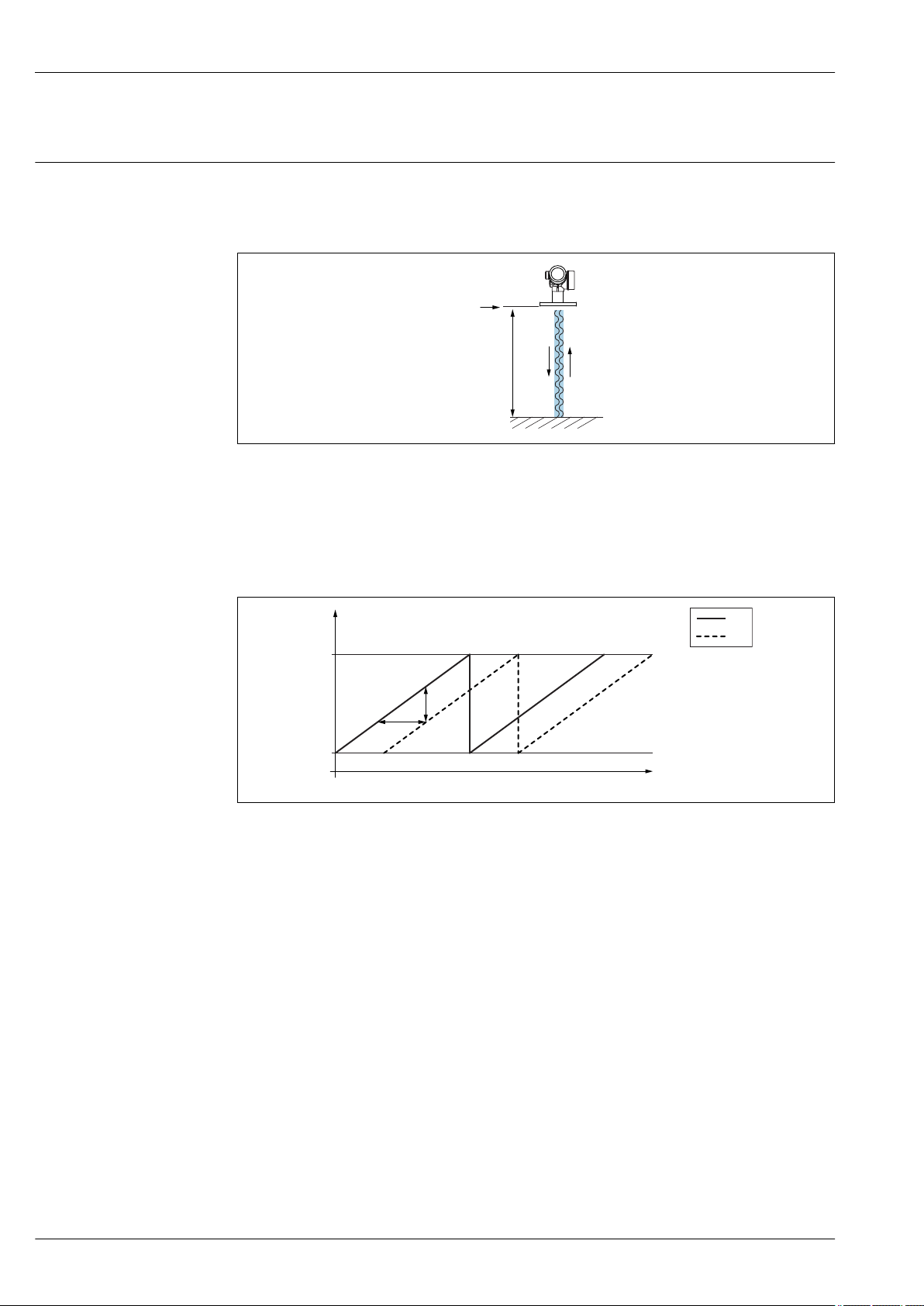
The Micropilot is a "downward-looking" measuring system, operating based on the frequency
modulated continuous wave method (FMCW). The antenna emits an electromagnetic wave at a
continuously varying frequency. This wave is reflected by the product and received again by the
antenna.
A0032017
1 FMCW principle: transmission and reflection of the continuous wave
R Reference point of measurement
D Distance between reference point and product surface
The frequency of this wave is modulated in the form of a sawtooth signal between two limit
frequencies f1 and f2:
2 FMCW principle: result of frequency modulation
1 Transmitted signal
2 Received signal
This results in the following difference frequency at any time between the transmitted signal and the
received signal:
Δf = k Δt
where Δt is the run time and k is the specified increase in frequency modulation.
Δt is given by the distance D between the reference point R and the product surface:
D = (c Δt) / 2
where c is the speed of propagation of the wave.
In summary, D can be calculated from the measured difference frequency Δf. D is then used to
determine the content of the tank or silo.
8 Endress+Hauser
A0023771
Micropilot FMR60
Input
Measured variable
The measured variable is the distance between the reference point and the product surface. The level
is calculated based on "E", the empty distance entered. Optionally, the level can be converted to other
variables (volume, mass) by linearization (32 value pairs).
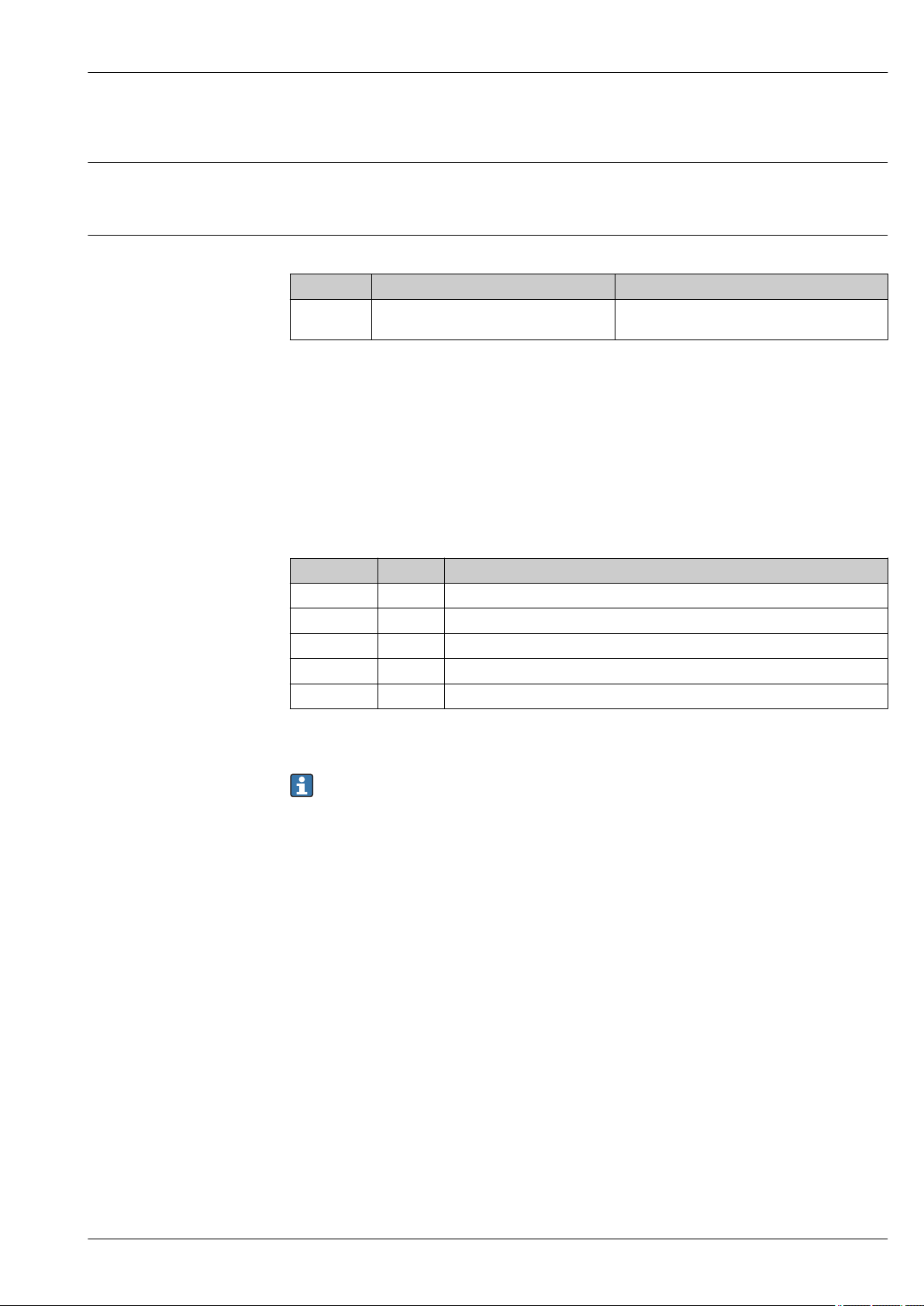
Measuring range Maximum measuring range
Device Antenna
FMR60 GA:
Drip-off, PTFE 50 mm / 2"
1) Feature 070 in the product structure
1)
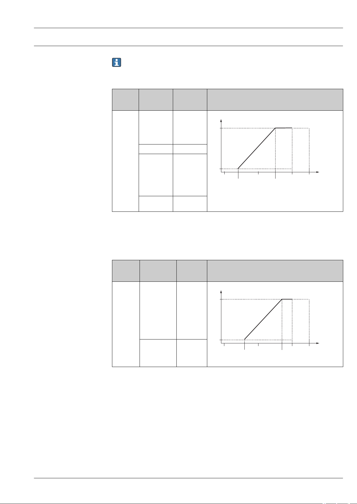
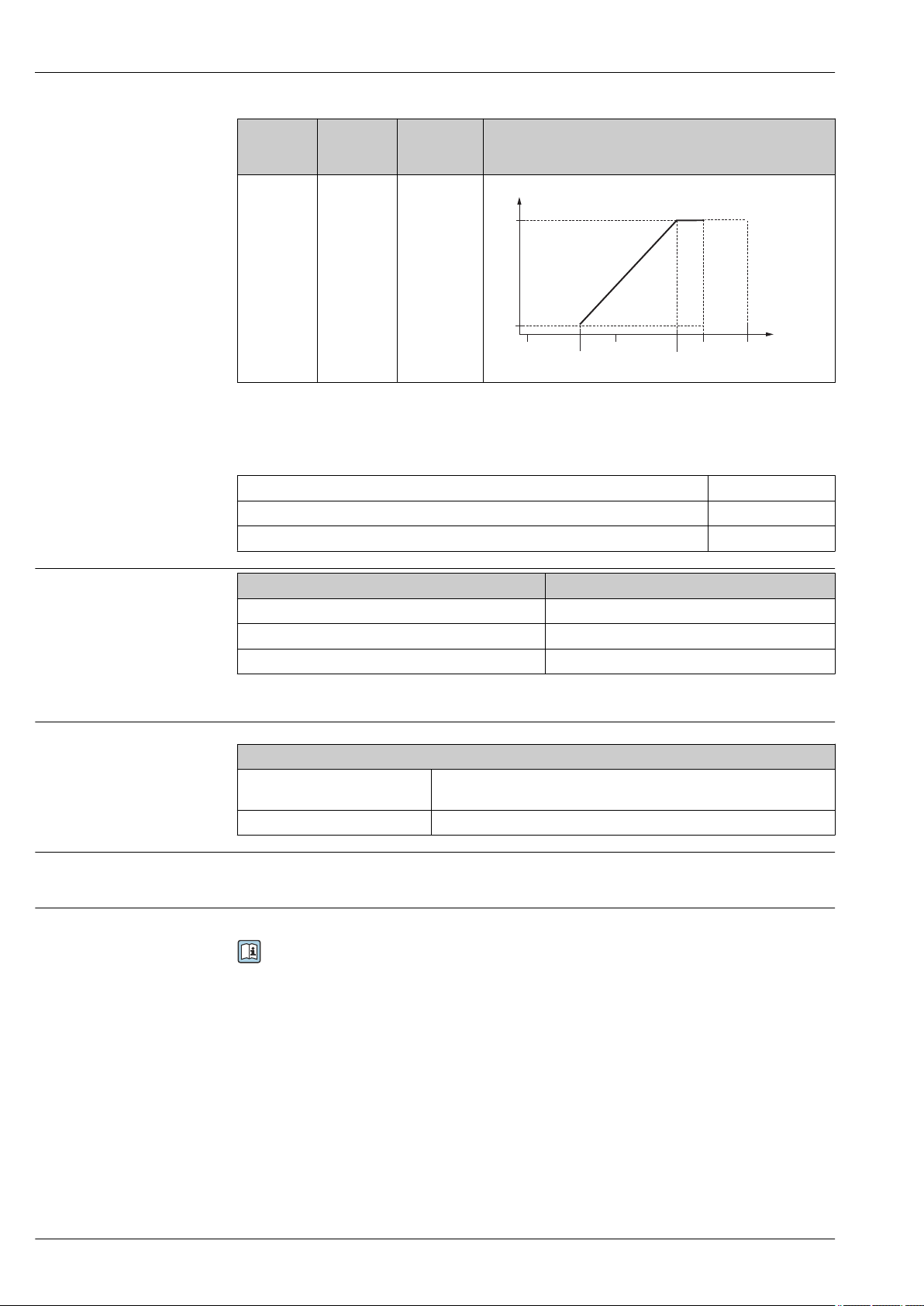
Usable measuring range
The usable measuring range depends on the antenna size, the medium's reflective properties, the
installation position and any possible interference reflections.
The following tables describe the groups of media as well as the achievable measuring range as a
function of application and media group. If the dielectric constant of a medium is unknown, it is
recommended to assume media group B to ensure a reliable measurement.
Media groups
Media group DC (εr) Example
A0 1.2 to 1.4 Butane, liquid nitrogen, liquefied hydrogen
A 1.4 to 1.9 non-conducting liquids, e.g. liquefied gas
B 1.9 to 4 non-conducting liquids, e.g. benzene, oil, toluene, …
C 4 to 10 e.g. concentrated acids, organic solvents, esters, aniline, alcohol, acetone, …
D > 10 conducting liquids, e.g. aqueous solutions, dilute acids and alkalis
Maximum measuring range
50 m (164 ft)
1)
1) NH3 falls into medium group A.
For dielectric constants (DC values) of many media commonly used in various industries refer
to:
• the Endress+Hauser DC manual (CP01076F)
• the Endress+Hauser "DC Values App" (available for Android and iOS)
Endress+Hauser 9
Micropilot FMR60
A0
A
B
C
D
7
12
(39)
23
(75)
40
(131)
50
(164)
A0
A
B
C
D
4
7
(23)
13
(43)
28
(92)
44
(144)
A0
A
B
C
D
2
4
(13)
7
(23)
15
(49)
25
(82)
FMR60
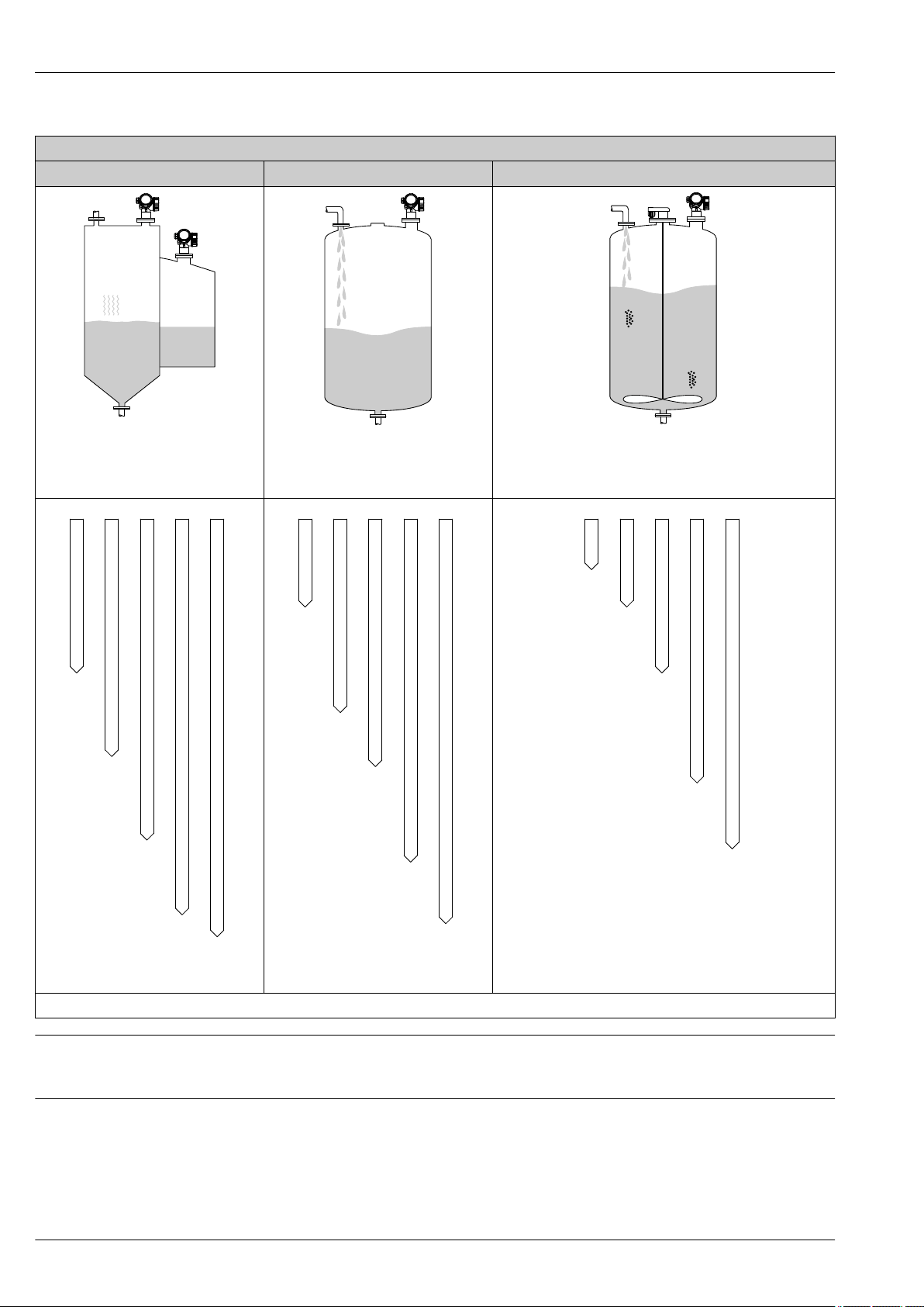
Storage tank Buffer tank Process tank with agitator
Calm product surface (e.g. intermittent
filling, filling from bottom, immersion
tubes)
A0034565
A0034566
Moving surfaces (e.g. continuous filling,
from above, mixing jets)
A0034567
Turbulent surface (e.g. filling from above, agitators, baffles)
A0034574
Measuring range [m (ft)]
A0034579
Operating frequency
Approx. 80 GHz
Up to 8 devices can be installed in the same tank without interfering with each other.
Transmission power
• Peak power: 6.3 mW
• Average output power: 63 µW
10 Endress+Hauser
A0034584

Micropilot FMR60
Output
Output signal HART
Signal coding FSK ±0.5 mA over current signal
Data transmission rate 1 200 Bit/s
Galvanic isolation Yes
Bluetooth® wireless technology
Device version Ordering feature 610 "Accessory mounted", option NF "Bluetooth"
Operation / configuration By the SmartBlue app.
Range under reference conditions > 10 m (33 ft)
Encryption Encrypted communication and password encryption prevent incorrect
Switch output
operation by unauthorized persons.
For HART devices, the switch output is available as an option. See product structure, feature 20:
"Power Supply, Output", option B: "2-wire; 4-20mA HART, switch output"
Switch output
Function Open collector switching output
Switching behavior Binary (conductive or non-conductive), switches when the programmable switch
point is reached
Failure mode non-conductive
Electrical connection values U = 16 to 35 VDC, I = 0 to 40 mA
Internal resistance RI < 880 Ω
The voltage drop at this internal resistance has to be taken into account on
planning the configuration. For example, the resulting voltage at a connected
relay must be sufficient to switch the relay.
Insulation voltage floating, Insulation voltage 1 350 VDC to power supply aund 500 VAC to ground
Switch point freely programmable, separately for switch-on and switch-off point
Switching delay freely programmable from 0 to 100 s, separately for switch-on and switch-off
point
Number of switching cycles corresponds to the measuring cycle
Signal source
device variables
Number of switching cycles unlimited
• Level linearized
• Distance
• Terminal voltage
• Electronic temperature
• Relative echo amplitude
• Diagnostic values, Advanced diagnostics
Endress+Hauser 11

Micropilot FMR60
Signal on alarm
Depending on the interface, failure information is displayed as follows:
• Current output (for HART devices)
– Failsafe mode selectable (in accordance with NAMUR Recommendation NE 43):
– Failsafe mode with user-selectable value: 3.59 to 22.5 mA
• Local display
– Status signal (in accordance with NAMUR Recommendation NE 107)
– Plain text display
• Operating tool via HART communication or service interface (CDI)
– Status signal (in accordance with NAMUR Recommendation NE 107)
– Plain text display
Linearization
The linearization function of the device allows the conversion of the measured value into any unit of
length or volume. Linearization tables for calculating the volume in cylindrical tanks are preprogrammed. Other linearization tables of up to 32 value pairs can be entered manually or semiautomatically.
Galvanic isolation
All circuits for the outputs are galvanically isolated from each other.
Protocol-specific data HART
Manufacturer ID 17 (0x11)
Device type ID 0x112B
HART specification 7.0
Device description files (DTM, DD) Information and files under:
HART load min. 250 Ω
HART device variables The measured values can be freely assigned to the device variables.
Supported functions • Burst mode
Minimum alarm: 3.6 mA
Maximum alarm (= factory setting): 22 mA
• www.endress.com
• www.fieldcommgroup.org
Measured values for PV (primary variable)
• Level linearized
• Distance
• Electronic temperature
• Relative echo amplitude
• Area of incoupling
• Analog output adv. diagnostics 1
• Analog output adv. diagnostics 2
Measured values for SV, TV, FV (second, third and fourth variable)
• Level linearized
• Distance
• Electronic temperature
• Terminal voltage
• Relative echo amplitude
• Absolute echo amplitude
• Area of incoupling
• Analog output adv. diagnostics 1
• Analog output adv. diagnostics 2
• Additional transmitter status
Wireless HART data
Minimum start-up voltage 16 V
Start-up current 3.6 mA
Start-up time 65 s
Minimum operating voltage 14.0 V
12 Endress+Hauser

Micropilot FMR60
Multidrop current 4.0 mA
Set-up time 15 s
Endress+Hauser 13
Terminal assignment
1
+
2
-
A
1
+
2
-
B
2
3
5
4
2
3
++
--
Y
I
6
1
2
Micropilot FMR60
Power supply
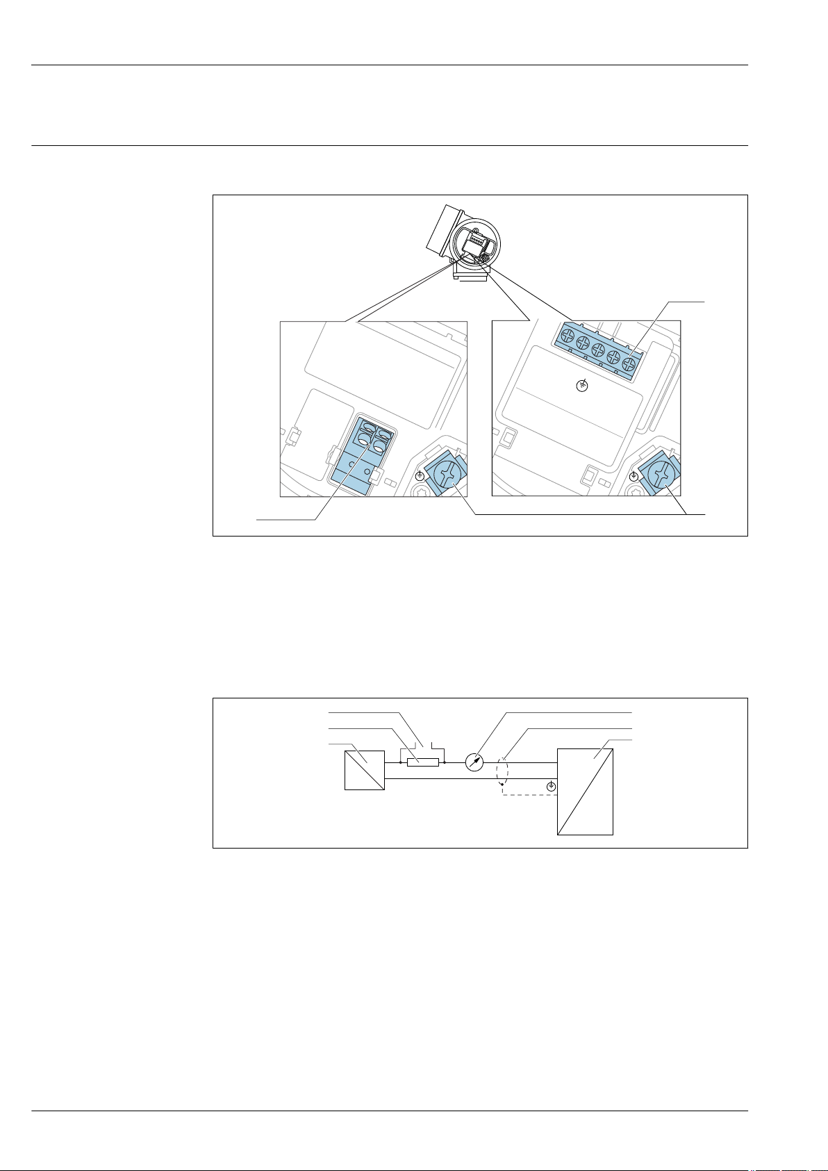
Terminal assignment 2-wire: 4-20 mA HART
3 Terminal assignment 2-wire: 4-20 mA HART
A Without integrated overvoltage protection
B With integrated overvoltage protection
1 Connection 4-20 mA HART passive: terminals 1 and 2, without integrated overvoltage protection
2 Connection 4-20 mA HART passive: terminals 1 and 2, with integrated overvoltage protection
3 Terminal for cable screen
Block diagram 2-wire: 4-20 mA HART
4 Block diagram 2-wire: 4-20 mA HART
1 Active barrier with power supply (e.g. RN221N); observe terminal voltage
2 HART communication resistor (≥ 250 Ω); observe maximum load
3 Connection for Commubox FXA195 or FieldXpert SFX350/SFX370 (via VIATOR Bluetooth modem)
4 Analog display device; observe maximum load
5 Cable screen; observe cable specification
6 Measuring device
A0036498
A0036499
14 Endress+Hauser

Micropilot FMR60
1
3
+
+
2
4
-
-
A
1
3
+
+
2
4
-
-
B
4
5
2
3
5
4
2
3
+
+
+
-
-
-
Y
I
6
7
1
2
3
4
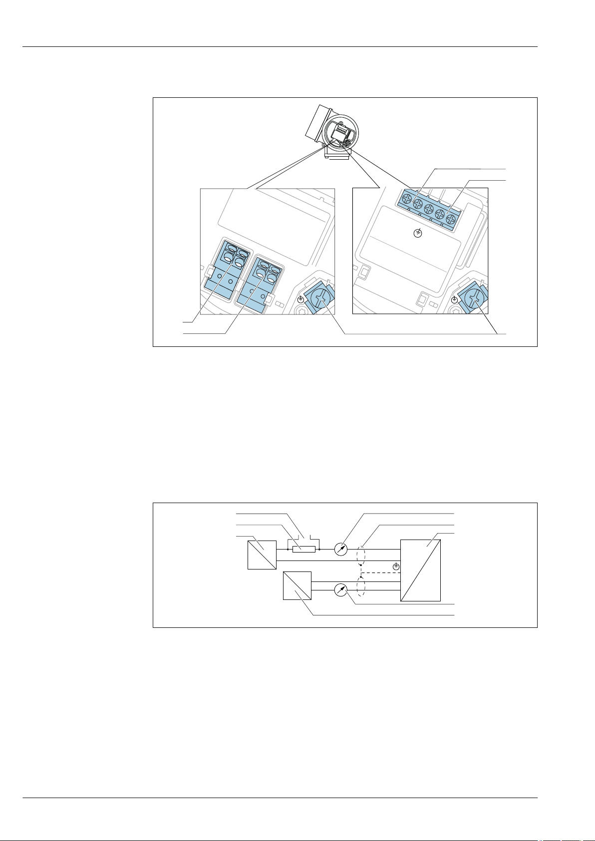
Terminal assignment 2-wire: 4-20 mA HART, switch output
5 Terminal assignment 2-wire: 4-20 mA HART, switch output
A Without integrated overvoltage protection
B With integrated overvoltage protection
1 Connection 4-20 mA HART passive: terminals 1 and 2, without integrated overvoltage protection
2 Connection switch output (Open Collector): terminals 3 and 4, without integrated overvoltage protection
3 Connection switch output (Open Collector): terminals 3 and 4, with integrated overvoltage protection
4 Connection 4-20 mA HART passive: terminals 1 and 2, with integrated overvoltage protection
5 Terminal for cable screen
Block diagram 2-wire: 4-20 mA HART, switch output
6 Block diagram 2-wire: 4-20 mA HART, switch output
1 Active barrier with power supply (e.g. RN221N); observe terminal voltage
2 HART communication resistor (≥ 250 Ω); observe maximum load
3 Connection for Commubox FXA195 or FieldXpert SFX350/SFX370 (via VIATOR Bluetooth modem)
4 Analog display device; observe maximum load
5 Cable screen; observe cable specification
6 Measuring device
7 Switch output (Open Collector)
A0036500
A0036501
Endress+Hauser 15
Terminal assignment 2-wire: 4-20 mA HART, 4-20 mA
1
3
+
+
2
4
-
-
A
1
3
+
+
2
4
-
-
B
4
5
2
3
5
4
2
3
+
+
+
+
-
-
-
-
Y
I
6
7
8
1
2
3
4
Micropilot FMR60
A0036500
7 Terminal assignment 2-wire: 4-20 mA HART, 4-20 mA
A Without integrated overvoltage protection
B With integrated overvoltage protection
1 Connection current output 1, 4-20 mA HART passive: terminals 1 and 2, without integrated overvoltage
protection
2 Connection current output 2, 4-20 mA: terminals 3 and 4, without integrated overvoltage protection
3 Connection current output 2, 4-20 mA: terminals 3 and 4, with integrated overvoltage protection
4 Connection current output 1, 4-20 mA HART passive: terminals 1 and 2, with integrated overvoltage
protection
5 Terminal for cable screen
Block diagram 2-wire: 4-20 mA HART, 4-20 mA
A0036502
8 Block diagram 2-wire: 4-20 mA HART, 4-20 mA
1 Active barrier with power supply (e.g. RN221N); observe terminal voltage
2 HART communication resistor (≥ 250 Ω); observe maximum load
3 Connection for Commubox FXA195 or FieldXpert SFX350/SFX370 (via VIATOR Bluetooth modem)
4 Analog display device; observe maximum load
5 Cable screen; observe cable specification
6 Measuring device
7 Analog display device; observe maximum load
8 Active barrier with power supply (e.g. RN221N), current output 2; observe terminal voltage
16 Endress+Hauser
Micropilot FMR60
3+
+
-
4-
R
i
3+
2
1
+
4-
R
i
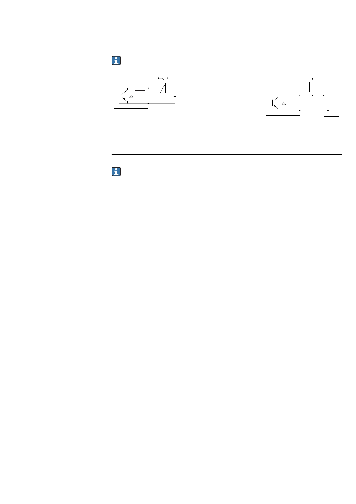
Connection examples for the switch output
For HART devices, the switch output is available as an option. See product structure, feature 20:
"Power Supply, Output", option B: "2-wire; 4-20 mA HART, switch output"
A0015909
9 Connection of a relay
Suitable relays (examples):
• Solid-state relay: Phoenix Contact OV-24DC/480AC/5 with mounting
rail connector UMK-1 OM-R/AMS
• Electromechanical relay: Phoenix Contact PLC-RSC-12DC/21
10 Connection of a digital input
1 Pull-up resistor
2 Digital input
For optimum interference immunity we recommend to connect an external resistor (internal
resistance of the relay or Pull-up resistor) of < 1 000 Ω.
A0015910
Endress+Hauser 17
Micropilot FMR60
2
1
3
4
4
2
3
1
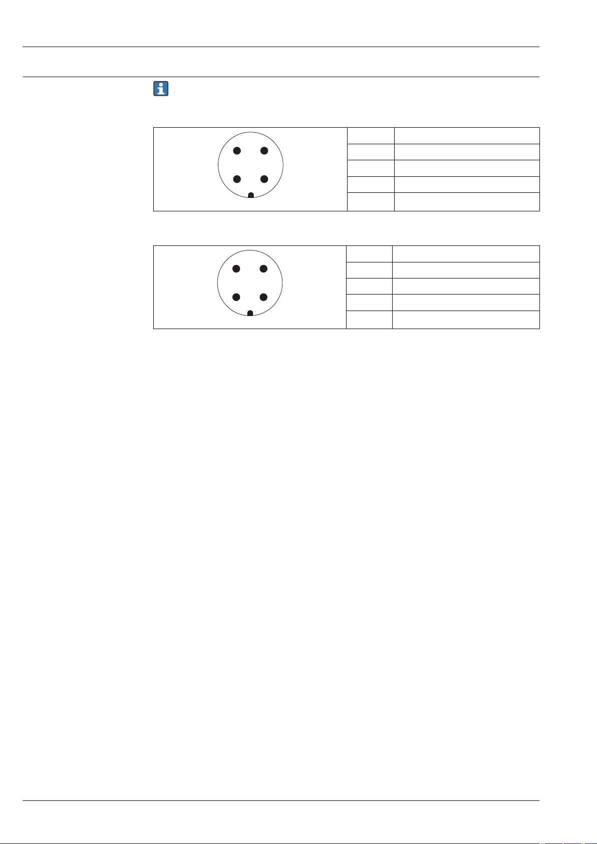
Device plug connectors
For the versions with fieldbus plug connector (M12 or 7/8"), the signal line can be connected
without opening the housing.
Pin assignment of the M12 plug connector
Pin Meaning
1 Signal +
2 not connected
3 Signal -
4 Ground
A0011175
Pin assignment of the 7/8" plug connector
Pin Meaning
1 Signal -
2 Signal +
3 Not connected
4 Screen
A0011176
18 Endress+Hauser
Micropilot FMR60
R [ ]W
U0[V]
10
14
25
20 30 35
0
500
R [ ]W
U0[V]
10
16
27
20 30 35
0
500
Supply voltage
An external power supply is necessary.
Various power supply units can be ordered as an accessory from Endress+Hauser.
2-wire, 4-20 mA HART, passive
"Power
supply,
output"
A:
2-wire;
4-20 mA
HART
"Approval"
1)
• Nonhazardous
• Ex nA
• Ex ic
• CSA GP
Ex ia / IS 14 to 30 V
• Ex d(ia) /
XP
• Ex ic(ia)
• Ex nA(ia)
• Ex ta / DIP
Ex ia + Ex
d(ia) / IS + XP
1) Feature 020 in the product structure
2) Feature 010 in the product structure
3) If the Bluetooth modem is used, the minimum supply voltage increases by 2 V.
4) At ambient temperatures TTa ≤ –20 °C, a terminal voltage U ≥ 16 V is required to start the device with the
minimum failure current (3.6 mA).
2)
Terminal
voltage U at
device
14 to 35 V
14 to 35 V
14 to 30 V
Maximum load R,
depending on the supply voltage
U0 of the power supply unit
3)
3)
3) 4)
A0031745
3)
hazardous
2)
Terminal
voltage U at
device
16 to 35 V
Maximum load R,
depending on the supply voltage
U0 of the power supply unit
3)
"Power
supply,
output"
B:
2-wire;
4-20 mA
HART,
switch
outpu
"Approval"
1)
• Non-
• Ex nA
• Ex nA(ia)
• Ex ic
• Ex ic(ia)
• Ex d(ia) / XP
• Ex ta / DIP
• CSA GP
• Ex ia / IS
16 to 30 V
3)
• Ex ia + Ex
d(ia) / IS +
XP
1) Feature 020 in the product structure
2) Feature 010 in the product structure
3) If the Bluetooth modem is used, the minimum supply voltage increases by 2 V.
A0031746
Endress+Hauser 19
Micropilot FMR60
R [ ]W
U0[V]
10
16
27
20 30 35
0
500
"Power
supply,
output"
C:
2-wire; 4-20
mA HART,
4-20 mA
1) Feature 020 in the product structure
2) Feature 010 in the product structure
3) If the Bluetooth modem is used, the minimum supply voltage increases by 2 V.
Integrated polarity reversal protection Yes
Permitted residual ripple with f = 0 to 100 Hz USS < 1 V
Permitted residual ripple with f = 100 to 10 000 Hz USS < 10 mV
"Approval"
1)
All 16 to 30 V
2)
Terminal
voltage U at
device
Maximum load R,
depending on the supply voltage
U0 of the power supply unit
3)
A0031746
Power consumption
Current consumption
Power supply failure
Potential equalization
"Power supply; Output"
A: 2-wire; 4-20mA HART < 0.9 W
B: 2-wire; 4-20mA HART, switch output < 0.9 W
C: 2-wire; 4-20mA HART, 4-20mA < 2 x 0.7 W
1) Feature 020 of the product structure
HART
Nominal current 3.6 to 22 mA the start-up current for multidrop mode can be parametrized
Breakdown signal (NAMUR NE43) adjustable: 3.59 to 22.5 mA
1)
(is set to 3.6 mA on delivery)
Power consumption
• Configuration is retained in the HistoROM (EEPROM).
• Error messages (incl. value of operated hours counter) are stored.
No special measures for potential equalization are required.
If the device is designed for hazardous areas, observe the information in the documentation
"Safety Instructions" (XA).
20 Endress+Hauser

Micropilot FMR60
Cable entries Connection of power supply and signal line
To be selected in feature 050 "Electrical connection"
• Gland M20; Material dependent on the approval:
– For Non-Ex, ATEX, IECEx, NEPSI Ex ia/ic:
Plastics M20x1.5 for cable ⌀5 to 10 mm (0.2 to 0.39 in)
– For Dust-Ex, FM IS, CSA IS, CSA GP, Ex nA:
Metal M20x1.5 for cable ⌀7 to 10 mm (0.28 to 0.39 in)
– For Ex d:
No gland available
• Thread
– ½" NPT
– G ½"
– M20 × 1.5
• Plug M12 / Plug 7/8"
Only available for Non-Ex, Ex ic, Ex ia
Connection of remote display FHX50
Feature 030 "Display, Operation" Cable entry for FHX50 connection
L: "Prepared for display FHX50 + M12 connection" M12 socket
M: "Prepared for display FHX50 + M16 gland, custom connection" M12 cable gland
N: "Prepared for display FHX50 + NPT1/2 thread, custom connection" NPT1/2 thread
1)
Cable specification
Overvoltage protection
• Devices without integrated overvoltage protection
Pluggable spring-force terminals for wire cross-sections 0.5 to 2.5 mm2 (20 to 14 AWG)
• Devices with integrated overvoltage protection
Screw terminals for wire cross-sections 0.2 to 2.5 mm2 (24 to 14 AWG)
• For ambient temperature TU≥60 °C (140 °F): use cable for temperature TU +20 K.
HART
• A normal device cable suffices if only the analog signal is used.
• A shielded cable is recommended if using the HART protocol. Observe grounding concept of the
plant.
If the measuring device is used for level measurement in flammable liquids which requires the use of
overvoltage protection according to DIN EN 60079-14, standard for
test procedures 60060-1 (10 kA, pulse 8/20 μs), an overvoltage protection module has to be
installed.
Integrated overvoltage protection module
An integrated overvoltage protection module is available for 2-wire HART devices.
Product structure: Feature 610 "Accessory mounted", option NA "Overvoltage protection".
Technical data
Resistance per channel 2 × 0.5 Ω max.
Threshold DC voltage 400 to 700 V
Threshold impulse voltage < 800 V
Capacitance at 1 MHz < 1.5 pF
Nominal arrest impulse voltage (8/20 μs) 10 kA
External overvoltage protection module
HAW562 or HAW569 from Endress+Hauser are suited as external overvoltage protection.
1) The material of the gland is dependent on the housing type; GT19 (plastic housing) and GT20 (aluminum housing): nickel-coated brass (CuZn).
Endress+Hauser 21
Performance characteristics
0.8 (2.62)
4 (0.16)
1 (0.04)
-1 (-0.04)
-4 (-0.16)
D [m (!)]
∆
[mm (in)]
R
0
Micropilot FMR60
Reference operating conditions
Reference accuracy
• Temperature = +24 °C (+75 °F) ±5 °C (±9 °F)
• Pressure = 960 mbar abs. (14 psia) ±100 mbar (±1.45 psi)
• Humidity = 60 % ±15 %
• Reflector: metal plate with diameter ≥ 1 m (40 in)
• No major interference reflections inside the signal beam
Typical data under reference operating conditions: DIN EN IEC 61298-2 / DIN EN IEC 60770-1;
percentage values in relation to the span.
Output: digital analog
Accuracy (Sum of nonlinearity, nonrepeatability
and hysteresis)
Non-repeatability
1) Add error of the analogous value to the digital value.
2) If the reference conditions are not met, the offset/zero point arising from the mounting conditions may be
up to ±4 mm (0.16 in). This additional offset/zero point can be compensated for by entering a correction
(parameter "level correction") during commissioning.
3) The non-repeatability is already considered in the accuracy.
2)
3)
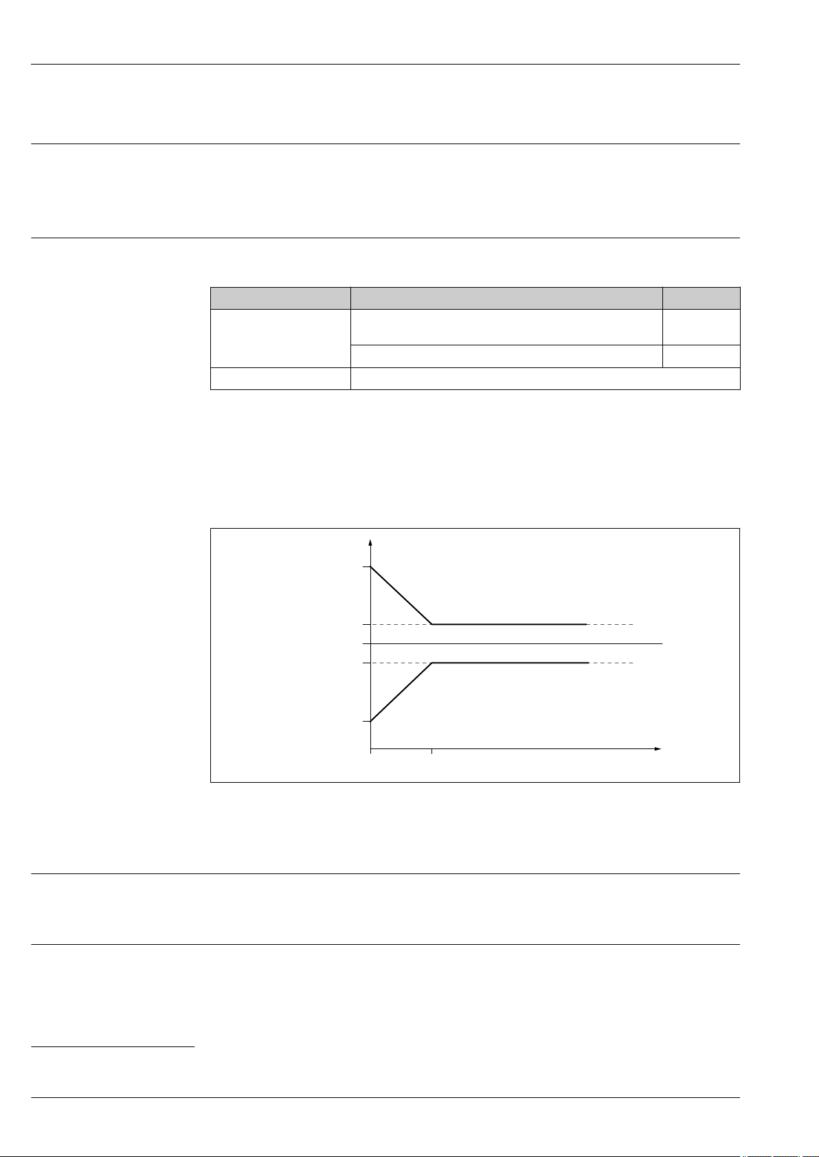
Measuring distance up to 0.8 m (2.62 ft): max.
±4 mm (±0.16 in)
Measuring distance > 0.8 m (2.62 ft): ±1 mm (±0.04 in) ±0.02 %
≤ 1 mm (0.04 in)
1)
±0.03 %
Differing values in near-range applications
11 Maximum measured error in near-range applications
Δ Maximum measured error
R Reference point of the distance measurement
D Distance from reference point of antenna
Measured value resolution
Dead band according to DIN EN IEC 61298-2 / DIN EN IEC 60770-1:
• Digital: 1 mm
• Analog: 1 µA
Response time
The response time can be configured. The following step response times (in accordance with
DIN EN IEC 61298-2 / DIN EN IEC 60770-1)
2)
are when damping is switched off:
2) According to DIN EN IEC 61298-2 / DIN EN IEC 60770-1, the step response time is the time that elapses after an abrupt change in the input
signal until the change in the output signal has adopted 90% of the steady-state value for the first time.
22 Endress+Hauser
A0032636
Loading...