


 Loading...
BA01784P/00/EN/02.19
71440622
2019-05-31
Products |
Solutions |
Services |
|
|
|
Operating Instructions
Cerabar PMP23
IO-Link
Process pressure measurement
Pressure transducer for safe measurement and monitoring of absolute and gauge pressure
Cerabar PMP23 IO-Link
|
|
|
|
|
|
|
|
|
|
|
|
|
|
|
|
|
|
|
|
|
|
|
|
|
|
|
|
|
|
|
|
|
|
|
|
|
|
|
|
|
|
|
|
|
ORDER CODE: |
|
|
|
|
|
|
|
|
|
|
|
|
|
|
|
|
|
|
|
|
XXXXX-XXXXXX |
|
|
|
|
|
|
|
|
|
|
|
|
|
|
|
||
1. |
|
|
SER. NO.: |
|
|
|
|
|
|
|
|
|
|
|
|
|
|
|
|
|
|
XXXXXXXXXXXX |
|
|
|
|
|
|
|
|
|
|
|
|
|
|
|
||||
|
|
|
EXT. ORD. CD.: |
|
|
|
|
|
|
|
|
|
|
|
|
|
|
|
|
|
|
|
|
XXX.XXXX.XX |
|
|
|
|
|
|
|
|
|
|
|
|
|
|
|
||
|
|
|
|
|
|
|
|
|
|
|
|
|
|
|
|
|
|
|
|
|
|
|
|
|
|
|
|
|
|
|
|
|
|
|
|
|
|
|
|
|
|
|
|
|
|
|
|
|
|
|
|
|
|
|
|
|
|
|
|
|
|
|
|
|
|
|
|
|
|
|
|
|
|
|
|
|
|
|
|
|
|
|
|
|
|
|
|
|
|
|
|
|
|
|
|
|
|
|
|
|
|
|
|
|
|
|
|
|
|
|
|
|
|
|
|
|
|
|
|
|
|
|
|
|
|
|
|
|
|
|
|
|
|
|
|
|
|
|
|
|
|
|
|
|
|
|
|
|
|
Serial number |
|
|
|
|
|
|
|
|
|
|
|
|
|
|
|
|
|
|||||
|
|
|
|
|
|
|
|
|
|
|
|
|
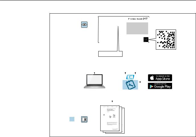
2. |
www.endress.com/deviceviewer |
|
|
|
|
|
Endress+Hauser |
|||||
|
|
|
|
|
|
|
|
|
|
|
Operations App |
|
|
|
|
|
|
|
|
|
|
|
|
|
|
|
|
|
|
|
|
|
|
|
|
|
|
|
|
|
|
|
|
|
|
|
|
|
|
|
|
|
|
|
|
|
|
|
|
|
|
|
|
|
|
|
|
|
|
|
|
|
|
|
|
|
|
|
|
|
|
|
|
|
|
|
|
|
|
|
3.
A0023555
•Make sure the document is stored in a safe place such that it is always available when working on or with the device.
•To avoid danger to individuals or the facility, read the "Basic safety instructions" section carefully, as well as all other safety instructions in the document that are specific to working procedures.
•The manufacturer reserves the right to modify technical data without prior notice. Your Endress+Hauser distributor will supply you with current information and updates to these Operating Instructions.
2 |
Endress+Hauser |

Cerabar PMP23 IO-Link |
Table of contents |
|
|
Table of contents
1 |
About this document . . . . . . . . . . . . . . . |
. 4 |
1.1 |
Document function . . . . . . . . . . . . . . . . . . . . . |
4 |
1.2 |
Symbols used . . . . . . . . . . . . . . . . . . . . . . . . . |
. 4 |
1.3 |
Documentation . . . . . . . . . . . . . . . . . . . . . . . . |
5 |
1.4 |
Terms and abbreviations . . . . . . . . . . . . . . . . . |
6 |
1.5 |
Turn down calculation . . . . . . . . . . . . . . . . . . . |
7 |
1.6 |
Registered trademarks . . . . . . . . . . . . . . . . . . . |
7 |
2 |
Basic safety instructions . . . . . . . . . . . . |
8 |
2.1 |
Requirements concerning the staff . . . . . . . . . . |
8 |
2.2 |
Designated use . . . . . . . . . . . . . . . . . . . . . . . . |
8 |
2.3 |
Workplace safety . . . . . . . . . . . . . . . . . . . . . . . |
9 |
2.4 |
Operational safety . . . . . . . . . . . . . . . . . . . . . . |
9 |
2.5 |
Product safety . . . . . . . . . . . . . . . . . . . . . . . . . |
9 |
3 |
Product description . . . . . . . . . . . . . . . . |
10 |
3.1 |
Product design . . . . . . . . . . . . . . . . . . . . . . . . |
10 |
3.2 |
Function . . . . . . . . . . . . . . . . . . . . . . . . . . . . |
10 |
4Incoming acceptance and product
|
identification . . . . . . . . . . . . . . . . . . . . . |
11 |
4.1 |
Incoming acceptance . . . . . . . . . . . . . . . . . . . |
11 |
4.2 |
Product identification . . . . . . . . . . . . . . . . . . . |
12 |
4.3 |
Storage and transport . . . . . . . . . . . . . . . . . . |
12 |
5 |
Installation . . . . . . . . . . . . . . . . . . . . . . . |
14 |
5.1 |
Mounting dimensions . . . . . . . . . . . . . . . . . . |
14 |
5.2 |
Installation conditions . . . . . . . . . . . . . . . . . . |
14 |
5.3 |
Influence of the installation position . . . . . . . . |
14 |
5.4 |
Mounting location . . . . . . . . . . . . . . . . . . . . . |
15 |
5.5Mounting of the profile seal for universal
process mounting adapter . . . . . . . . . . . . . . . 16 5.6 Post-installation check . . . . . . . . . . . . . . . . . . 16
6 |
Electrical connection . . . . . . . . . . . . . . |
17 |
6.1 |
Connecting the measuring unit . . . . . . . . . . . . |
17 |
6.2 |
Switching capacity . . . . . . . . . . . . . . . . . . . . . |
18 |
6.3 |
Connection data . . . . . . . . . . . . . . . . . . . . . . . |
18 |
6.4 |
Post-connection check . . . . . . . . . . . . . . . . . . |
18 |
7 |
Operation options . . . . . . . . . . . . . . . . . |
20 |
7.1 |
Operation with an operating menu . . . . . . . . . |
20 |
8 |
System integration . . . . . . . . . . . . . . . . |
21 |
8.1 |
Process data . . . . . . . . . . . . . . . . . . . . . . . . . |
21 |
8.2Reading out and writing device data (ISDU –
Indexed Service Data Unit) . . . . . . . . . . . . . . . 21
9 |
Commissioning . . . . . . . . . . . . . . . . . . . . |
24 |
9.1 |
Function check . . . . . . . . . . . . . . . . . . . . . . . |
24 |
9.2 |
Commissioning with an operating menu . . . . . |
24 |
9.3 |
Configuring pressure measurement . . . . . . . . |
25 |
9.4 |
Performing position adjustment . . . . . . . . . . . |
27 |
9.5 |
Configuring process monitoring . . . . . . . . . . . |
29 |
9.6 |
Current output . . . . . . . . . . . . . . . . . . . . . . . . |
33 |
9.7 |
Application examples . . . . . . . . . . . . . . . . . . . |
36 |
10 |
Diagnostics and troubleshooting . . . |
37 |
10.1 |
Troubleshooting . . . . . . . . . . . . . . . . . . . . . . |
37 |
10.2 |
Diagnostic events . . . . . . . . . . . . . . . . . . . . . . |
38 |
10.3 |
Behavior of the device in the event of a fault . . |
40 |
10.4Behavior of current output in the event of a
fault . . . . . . . . . . . . . . . . . . . . . . . . . . . . . . . 40 10.5 Resetting to factory settings (reset) . . . . . . . . 41
11 |
Maintenance . . . . . . . . . . . . . . . . . . . . . . |
41 |
11.1 |
Exterior cleaning . . . . . . . . . . . . . . . . . . . . . . |
41 |
12 |
Repairs . . . . . . . . . . . . . . . . . . . . . . . . . . . |
42 |
12.1 |
General notes . . . . . . . . . . . . . . . . . . . . . . . . |
42 |
12.2 |
Return . . . . . . . . . . . . . . . . . . . . . . . . . . . . . . |
42 |
12.3 |
Disposal . . . . . . . . . . . . . . . . . . . . . . . . . . . . |
42 |
13 |
Overview of the operating menu . . . |
43 |
14 |
Description of device parameters . . . |
44 |
14.1 |
Identification . . . . . . . . . . . . . . . . . . . . . . . . . |
44 |
14.2 |
Diagnostics . . . . . . . . . . . . . . . . . . . . . . . . . . |
44 |
14.3 |
Parameters . . . . . . . . . . . . . . . . . . . . . . . . . . |
46 |
14.4 |
Observation . . . . . . . . . . . . . . . . . . . . . . . . . |
57 |
15 |
Accessories . . . . . . . . . . . . . . . . . . . . . . . |
58 |
15.1 |
Weld-in adapter . . . . . . . . . . . . . . . . . . . . . . |
58 |
15.2 |
Process adapter M24 . . . . . . . . . . . . . . . . . . . |
58 |
15.3 |
M12 plug connectors . . . . . . . . . . . . . . . . . . . |
59 |
16 |
Technical data . . . . . . . . . . . . . . . . . . . . |
60 |
16.1 |
Input . . . . . . . . . . . . . . . . . . . . . . . . . . . . . . . |
60 |
16.2 |
Output . . . . . . . . . . . . . . . . . . . . . . . . . . . . . |
62 |
16.3Performance characteristics of metal process
isolating diaphragm . . . . . . . . . . . . . . . . . . . . 64 16.4 Environment . . . . . . . . . . . . . . . . . . . . . . . . . 66 16.5 Process . . . . . . . . . . . . . . . . . . . . . . . . . . . . . 67
Index . . . . . . . . . . . . . . . . . . . . . . . . . . . . . . . . . . 68
Endress+Hauser |
3 |

About this document |
Cerabar PMP23 IO-Link |
|
|
1About this document
1.1Document function
These Operating Instructions contain all the information that is required in various phases of the life cycle of the device: from product identification, incoming acceptance and storage, to mounting, connection, operation and commissioning through to troubleshooting, maintenance and disposal.
1.2Symbols used
1.2.1Safety symbols
Symbol Meaning
DANGER!
 DANGER This symbol alerts you to a dangerous situation. Failure to avoid this situation will result in serious or fatal injury.
WARNING!
 WARNING This symbol alerts you to a dangerous situation. Failure to avoid this situation can result in serious or fatal injury.
CAUTION!
 CAUTION This symbol alerts you to a dangerous situation. Failure to avoid this situation can result in minor or medium injury.
NOTICE!
NOTICE This symbol contains information on procedures and other facts which do not result in personal injury.
1.2.2Electrical symbols
Symbol |
Meaning |
Symbol |
Meaning |
|
|
|
|
|
Protective ground connection |
|
Ground connection |
|
A terminal which must be connected |
|
A grounded terminal which, as far as |
|
to ground prior to establishing any |
|
the operator is concerned, is |
|
other connections. |
|
grounded via a grounding system. |
|
|
|
|
1.2.3 |
Tool symbols |
Symbol |
Meaning |
|
Open-ended wrench |
A0011222
1.2.4Symbols for certain types of information
Symbol Meaning
Permitted
Procedures, processes or actions that are permitted.
Forbidden
Procedures, processes or actions that are forbidden.
Tip
Indicates additional information.
4 |
Endress+Hauser |
Cerabar PMP23 IO-Link |
About this document |
Symbol |
Meaning |
|
Reference to documentation |
A |
Reference to page |
Reference to graphic
1. , 2. , 3. … Series of steps
Result of a step
Visual inspection
1.2.5Symbols in graphics
|
Symbol |
Meaning |
|||||
|
|
|
|
|
|
|
|
1, 2, 3 ... |
Item numbers |
||||||
|
|
|
|
|
|
|
|
|
|
|
|
|
|
|
Series of steps |
|
1. |
, |
2. |
, |
3. |
… |
|
|
|
||||||
A, B, C, ... |
Views |
||||||
|
|
|
|
|
|
|
|
1.3Documentation
The document types listed are available:
In the Download Area of the Endress+Hauser Internet site: www.endress.com →
Download
1.3.1Technical Information (TI): planning aid for your device
TI01203P
The document contains all the technical data on the device and provides an overview of the accessories and other products that can be ordered for the device.
1.3.2Brief Operating Instructions (KA): getting the 1st measured value quickly
KA01164P
These instructions contain all the essential information from incoming acceptance to initial commissioning.
Endress+Hauser |
5 |

About this document |
Cerabar PMP23 IO-Link |
|
|
1.4Terms and abbreviations
|
|
|
1 |
|
|
|
|
|
2 |
|
|
|
|
3 |
|
|
|
|
|
4 |
|
|
|
|
|
|
|
|
P |
|
0 |
|
|
|
|
LRL |
LRV |
URV |
URL |
MWP |
OPL |
A0029505
Item |
Term/ |
Explanation |
|
abbreviation |
|
|
|
|
1 |
OPL |
The OPL (over pressure limit = sensor overload limit) for the measuring device |
|
|
depends on the lowest-rated element, with regard to pressure, of the selected |
|
|
components, i.e. the process connection has to be taken into consideration in |
|
|
addition to the measuring cell. Also observe pressure-temperature dependency. For |
|
|
the relevant standards and additional notes, see the "Pressure specifications" section |
|
|
→ 67 . |
|
|
The OPL may only be applied for a limited period of time. |
|
|
|
2 |
MWP |
The MWP (maximum working pressure) for the sensors depends on the lowest- |
|
|
rated element, with regard to pressure, of the selected components, i.e. the process |
|
|
connection has to be taken into consideration in addition to the measuring cell. |
|
|
Also observe pressure-temperature dependency. For the relevant standards and |
|
|
additional notes, see the "Pressure specifications" section → 67 . |
|
|
The MWP may be applied at the device for an unlimited period. |
|
|
The MWP can also be found on the nameplate. |
|
|
|
3 |
Maximum sensor |
Span between LRL and URL |
|
measuring range |
This sensor measuring range is equivalent to the maximum calibratable/adjustable |
|
|
span. |
|
|
|
4 |
Calibrated/ |
Span between LRV and URV |
|
adjusted span |
Factory setting: 0 to URL |
|
|
Other calibrated spans can be ordered as customized spans. |
|
|
|
p |
- |
Pressure |
|
|
|
- |
LRL |
Lower range limit |
|
|
|
- |
URL |
Upper range limit |
|
|
|
- |
LRV |
Lower range value |
|
|
|
- |
URV |
Upper range value |
|
|
|
- |
TD (turn down) |
Turn down |
|
|
The turn down is preset at the factory and cannot be changed. |
|
|
Example - see the following section. |
|
|
|
6 |
Endress+Hauser |

Cerabar PMP23 IO-Link |
About this document |
|
|
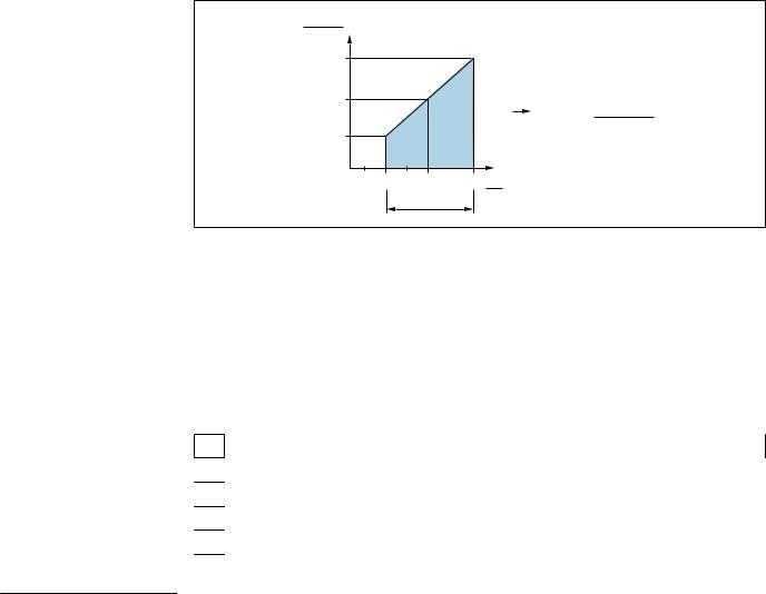
1.5Turn down calculation
|
|
|
1 = 2 |
|
3 |
|
LRL LRV |
URV |
URL |
||||
|
|
|
|
|
|
|
|
|
|
|
|
|
|
|
|
|
|
|
|
|
|
|
|
|
|
|
|
A0029545
1 |
Calibrated/adjusted span |
|
|
|
|||
2 |
Zero point-based span |
|
|
|
|
||
3 |
URL sensor |
|
|
|
|
||
|
|
|
|
|
|
||
Example |
|
|
|
|
|||
|
|
|
|
|
|
||
• Sensor:10 bar (150 psi) |
|
|
|
• Calibrated/adjusted span: 0 to 5 bar (0 to 75 psi) |
|||
• Upper range value (URL) = 10 bar (150 psi) |
• Lower range value (LRV) = 0 bar (0 psi) |
||||||
Turn down (TD): |
|
|
|
• Upper range value (URV) = 5 bar (75 psi) |
|||
|
|
|
|
||||
|
TD |
= |
|
URL |
|
|
|
|
|
|
|
|
|
||
|
|URV |
- |
LRV| |
|
|||
|
|
|
|
||||
|
|
|
10 bar (150 psi) |
|
|||
|
TD |
= |
|
|
|
= |
2 |
|
|5 bar (75 psi) |
- |
|
||||
|
|
|
0 bar (0 psi)| |
|
|||
In this example, the TD is 2:1.
This span is based on the zero point.
1.6Registered trademarks
is a registered trademark of the IO-Link company group.
Endress+Hauser |
7 |
Basic safety instructions |
Cerabar PMP23 IO-Link |
|
|
2Basic safety instructions
2.1Requirements concerning the staff
The personnel for installation, commissioning, diagnostics and maintenance must fulfill the following requirements:
Trained, qualified specialists: must have a relevant qualification for this specific function and task
Are authorized by the plant owner/operator
Are familiar with federal/national regulations
Before beginning work, the specialist staff must have read and understood the instructions in the Operating Instructions and supplementary documentation as well as in the certificates (depending on the application)
Following instructions and basic conditions
The operating personnel must fulfill the following requirements:
Being instructed and authorized according to the requirements of the task by the facility's owner-operator
Following the instructions in these Operating Instructions
2.2Designated use
2.2.1Application and media
The Cerabar is used to measure absolute and gauge pressure in gases, vapors and liquids. The process-wetted materials of the measuring device must have an adequate level of resistance to the media.
The measuring device may be used for the following measurements (process variables)
•in compliance with the limit values specified under "Technical data"
•in compliance with the conditions that are listed in this manual.
Measured process variable
Gauge pressure or absolute pressure
Calculated process variable
Pressure
2.2.2Incorrect use
The manufacturer is not liable for damage caused by improper or non-designated use.
Verification for borderline cases:
For special fluids and fluids for cleaning, Endress+Hauser is glad to provide assistance in verifying the corrosion resistance of process-wetted materials, but does not accept any warranty or liability.
2.2.3Residual risks
When in operation, the housing may reach a temperature close to the process temperature.
Danger of burns from contact with surfaces!
For elevated process temperatures, ensure protection against contact to prevent burns.
8 |
Endress+Hauser |
Cerabar PMP23 IO-Link |
Basic safety instructions |
|
|
2.3Workplace safety
For work on and with the device:
Wear the required personal protective equipment according to federal/national regulations.
Switch off the supply voltage before connecting the device.
2.4Operational safety
Risk of injury!
Operate the device in proper technical condition and fail-safe condition only.
The operator is responsible for interference-free operation of the device.
Conversions to the device
Unauthorized modifications to the device are not permitted and can lead to unforeseeable dangers.
If, despite this, modifications are required, consult with Endress+Hauser.
Hazardous area
To eliminate the risk of danger to persons or the facility when the device is used in the approval-related area (e.g. pressure equipment safety):
Check the nameplate to verify if the device ordered can be put to its intended use in the approval-related area.
2.5Product safety
This measuring device is designed in accordance with good engineering practice to meet state-of-the-art safety requirements, has been tested, and left the factory in a condition in which it is safe to operate.
It meets general safety standards and legal requirements. It also complies with the EU directives listed in the device-specific EU Declaration of Conformity. Endress+Hauser confirms this by affixing the CE mark to the device.
Endress+Hauser |
9 |

Product description |
Cerabar PMP23 IO-Link |
|
|
3Product description
3.1Product design
Overview |
|
Item |
Description |
C - 1 |
C - 2 |
C- 1 |
M12 plug |
|
|
|
Housing cap made of plastic |
|
|
C- 2 |
M12 plug |
|
|
|
IP69: metal housing cap |
|
A0021987 |
A0027289 |
|
|
D |
D |
Housing |
|
|
E |
Process connection (sample illustration) |
E
A0027227
3.2Function
3.2.1Calculating the pressure
Devices with metallic process isolating diaphragm
The process pressure deflects the metal process isolating diaphragm of the sensor and a fill fluid transfers the pressure to a Wheatstone bridge (semiconductor technology). The pressure-dependent change in the bridge output voltage is measured and evaluated.
10 |
Endress+Hauser |

Cerabar PMP23 IO-Link |
Incoming acceptance and product identification |
|
|
4Incoming acceptance and product identification
4.1Incoming acceptance
DELIVERY NOTE
A0028673

 1 = 2
1 = 2 
A0016870
Is the order code on the delivery note (1) identical to the order code on the product sticker (2)?
A0022100
A0028673
A0022103
Are the goods undamaged?
A0028673
DELIVERY NOTE
A0022105
Do the data on the nameplate correspond to the order specifications and the delivery note?
If one of these conditions does not apply, please contact your
Endress+Hauser sales office.
Endress+Hauser |
11 |

Incoming acceptance and product identification |
Cerabar PMP23 IO-Link |
|
|
4.2Product identification
The following options are available for the identification of the measuring device:
•Nameplate specifications
•Order code with a breakdown of the device features on the delivery note
•Enter the serial numbers from the nameplates in W@M Device Viewer (www.endress.com/deviceviewer): All the information about the measuring device is displayed.
For an overview of the technical documentation provided, enter the serial number from the nameplates in W@M Device Viewer (www.endress.com/deviceviewer)
4.2.1Manufacturer address
Endress+Hauser SE+Co. KG Hauptstraße 1
79689 Maulburg, Germany
Address of the manufacturing plant: See nameplate.
4.2.2Nameplate
1
2 Cerabar
3
4
5
Made in Germany,
D-79689 Maulburg
Ord. cd.:
 Ser. no.:
  Ext. ord. cd.:
Date:
TAG:
A0024456
1 Manufacturer's address
2 Device name
3 Order number
4Serial number
5Extended order number
4.3Storage and transport
4.3.1Storage conditions
Use original packaging.
Store the measuring device in clean and dry conditions and protect from damage caused by shocks (EN 837-2).
Storage temperature range
–40 to +85 °C (–40 to +185 °F)
12 |
Endress+Hauser |

Cerabar PMP23 IO-Link |
Incoming acceptance and product identification |
|
|
4.3.2Transporting the product to the measuring point
LWARNING
Incorrect transport!
Housing and diaphragm may become damaged, and there is a risk of injury!
Transport the measuring device to the measuring point in its original packaging or by the process connection.
Endress+Hauser |
13 |

Installation |
Cerabar PMP23 IO-Link |
|
|
5Installation
5.1Mounting dimensions
For dimensions, see the "Mechanical construction" section in the Technical Information.
5.2Installation conditions
•Moisture must not penetrate the housing when mounting the device, establishing the electrical connection and during operation.
•For M12 plug made of metal: Do not remove the protection cap (only in IP69) of M12 plug connection until shortly before electrical connection.
•Do not clean or touch process isolating diaphragms with hard and/or pointed objects.
•Do not remove process isolating diaphragm protection until shortly before installation.
•Always tighten the cable entry firmly.
•Point the cable and connector downwards where possible to prevent moisture from entering (e.g. rain or condensation water).
•Protect housing against impact.
•For devices with gauge pressure sensor, the following applies:
NOTICE
If a heated device is cooled in the course of a cleaning process (by cold water, for example), a vacuum develops for a short time causing moisture to penetrate the sensor via the pressure compensation element (1).
Device could be destroyed!
In the event of this happening, mount the device in such a way that the pressure compensation element (1) is pointing downwards at an angle or to the side, if possible.
|
|
1 |
1 |
1 |
1 |
A0022252
5.3Influence of the installation position
Any orientation is possible. However, the orientation may cause a zero point shift i.e. the measured value does not show zero when the vessel is empty or partially full.
|
A |
B |
C |
|
|
|
A0024708 |
Type |
Process isolating diaphragm |
Process isolating diaphragm |
Process isolating diaphragm |
|
axis is horizontal (A) |
pointing upwards (B) |
pointing downwards (C) |
PMP23 |
Calibration position, no effect |
Up to +4 mbar (+0.058 psi) |
Up to –4 mbar (–0.058 psi) |
14 |
Endress+Hauser |

Cerabar PMP23 IO-Link |
Installation |
|
|
5.4Mounting location
5.4.1Pressure measurement
Pressure measurement in gases
Mount the device with shutoff device above the tapping point so that any condensate can flow into the process.
1
2
A0021904
1Device
2Shutoff device
Pressure measurement in vapors
For pressure measurement in vapors, use a siphon. The siphon reduces the temperature to almost ambient temperature. Mount the device with a shutoff device at the same height as the tapping point.
Advantage:
only minor/negligible heat effects on the device.
Note the max. permitted ambient temperature of the transmitter!
1
2
3
A0024395
1Device
2 Shutoff device
3Siphon
Pressure measurement in liquids
Mount the device with a shutoff device at the same height as the tapping point.
Endress+Hauser |
15 |
Installation |
|
|
|
|
|
|
|
|
|
|
|
|
Cerabar PMP23 IO-Link |
||||||
|
|
|
|
|
|
|
|
|
|
|
|
|
|
|
|
|
|
|
|
|
|
|
|
|
|
|
|
|
|
|
|
|
|
|
|
|
|
|
|
|
|
|
|
|
|
|
|
|
|
|
|
|
|
|
|
|
|
|
|
|
|
|
|
|
|
|
|
|
|
|
|
|
|
|
|
|
|
|
|
2 1
A0024399
1Device
2Shutoff device
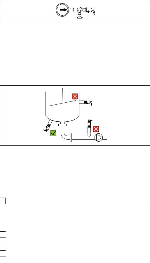
5.4.2Level measurement
•Always install the device below the lowest measuring point.
•Do not install the device at the following positions:
•In the filling curtain
•In the tank outlet
•in the suction area of a pump
•Or at a point in the tank which could be affected by pressure pulses from the agitator.
A0024405
5.5Mounting of the profile seal for universal process mounting adapter
For details on mounting, see KA00096F/00/A3.
5.6Post-installation check
Is the device undamaged (visual inspection)?
Does the device comply with the measuring point specifications? For example:
• Process temperature
•Process pressure
•Ambient temperature range
•Measuring range
Are the measuring point identification and labeling correct (visual inspection)?
Is the device adequately protected against precipitation and direct sunlight?
Are the securing screws tightened securely?
Is the pressure compensation element pointing downwards at an angle or to the side?
To prevent moisture from penetrating, ensure that the connecting cables/plugs are pointing downwards.
16 |
Endress+Hauser |

Cerabar PMP23 IO-Link |
Electrical connection |
|
|
6Electrical connection
6.1Connecting the measuring unit
6.1.1Terminal assignment
LWARNING
Risk of injury from the uncontrolled activation of processes!
Switch off the supply voltage before connecting the device.
Make sure that downstream processes are not started unintentionally.
LWARNING
Electrical safety is compromised by an incorrect connection!
In accordance with IEC/EN61010 a suitable circuit breaker must be provided for the device .
The device must be operated with a 500 mA fine-wire fuse (slow-blow).
Protective circuits against reverse polarity are integrated.
Connect the device in the following order:
1.Check that the supply voltage corresponds to the supply voltage indicated on the nameplate.
2.Connect the device in accordance with the following diagram.
Switch on the supply voltage.
Device |
M12 plug |
|
|
PMP23
2 |
1 |
L+ |
|
|
IO-LINK |
||
|
|
C/Q |
|
3 |
4 |
|
|
|
SIO |
||
|
|
L– |
|
|
|
|
A0034006
1 Supply voltage +
24-20 mA
3Supply voltage -
4 C/Q (IO-Link communication or SIO mode)
6.1.2 |
Supply voltage |
||
|
|
|
|
Electronic version |
Device |
Supply voltage |
|
|
|
|
|
IO-Link |
|
PMP23 |
10 to 30 V DC |
|
|
|
IO-Link communication is guaranteed only if the supply voltage is at least 18 V. |
|
|
|
|
6.1.3 |
Current consumption and alarm signal |
|
||
|
|
|
|
|
Electronic version |
Device |
Current consumption |
Alarm signal 1) |
|
IO-Link |
|
PMP23 |
Maximum current consumption: ≤ 300 mA |
|
|
|
|
|
|
1)For MAX alarm (factory setting)
Endress+Hauser |
17 |
Electrical connection |
Cerabar PMP23 IO-Link |
|
|
6.2Switching capacity
•Switch status ON: Ia ≤ 200 mA 1) 2); switch status OFF: Ia ≤1 mA
•Switch cycles: >10,000,000
•Voltage drop PNP: ≤2 V
•Overload protection: Automatic load testing of switching current;
•Max. capacitive load: 1 μF at max. supply voltage (without resistive load)
•Max. cycle duration: 0.5 s; min. ton: 40 μs
•Periodic disconnection from protective circuit in the event of overcurrent (f = 2 Hz) and "F804" displayed
6.3Connection data
6.3.1Load (for 4 to 20 mA devices )
In order to guarantee sufficient terminal voltage, a maximum load resistance RL (including line resistance) must not be exceeded depending on the supply voltage UB of the supply unit.
R L MAX |
|
|
|
|
[W] |
|
|
|
|
1022 |
|
|
|
|
587 |
|
|
2 |
|
|
|
|
R L MAX £ |
|
152 |
|
|
|
|
0 |
10 |
20 |
30 UB |
|
|
|
1 |
[V] |
|
|
|
|
|
U B - 6.5V
23MA
A0031107
1Power supply 10 to 30 V DC
2RLmax Maximum load resistance
UB Supply voltage
•Error current is output and "S803" displayed (output: MIN alarm current)
•Periodic checking to establish if it is possible to quit fault state
6.4Post-connection check
Is the device or cable undamaged (visual check)?
Do the cables comply with the requirements?
Do the mounted cables have adequate strain relief?
Are all the cable glands installed, firmly tightened and leak-tight?
Does the supply voltage match the specifications on the nameplate?
1)100 mA can be guaranteed over the entire temperature range for the switch output 1 x PNP + 4 to 20 mA output. For lower ambient temperatures, higher currents are possible but cannot be guaranteed. Typical value at 20 °C (68 °F) approx. 200 mA. 200 mA can be guaranteed over the entire temperature range for the "1 x PNP" switch output.
2)Larger currents are supported, thus deviating from the IO-Link standard.
18 |
Endress+Hauser |

Cerabar PMP23 IO-Link |
Electrical connection |
|
|
Is the terminal assignment correct ?
If required: has protective ground connection been established?
Endress+Hauser |
19 |

Operation options |
Cerabar PMP23 IO-Link |
|
|
7Operation options
7.1Operation with an operating menu
7.1.1IO-Link
IO-Link information
IO-Link is a point-to-point connection for communication between the measuring device and an IO-Link master. The measuring device features an IO-Link communication interface type 2 with a second IO function on pin 4. This requires an IO-Link-compatible assembly (IO-Link master) for operation. The IO-Link communication interface enables direct access to the process and diagnostic data. It also provides the option of configuring the measuring device while in operation.
Physical layer, the measuring device supports the following features:
•IO-Link specification: version 1.1
•IO-Link Smart Sensor Profile 2nd Edition (supports minimum scope of IdentClass)
•SIO mode: Yes
•Speed: COM2; 38.4 kBaud
•Minimum cycle time: 2.5 msec.
•Process data width: 32 bit
•IO-Link data storage: Yes
•Block configuration: Yes
IO-Link download
http://www.endress.com/download
•Select "Software" as the media type.
•Select "Device Driver" as the software type. Select IO-Link (IODD).
•In the "Text Search" field enter the device name.
https://ioddfinder.io-link.com/
Search by
•Manufacturer
•Article number
•Product type
7.1.2Structure of the operating menu
The menu structure has been implemented according to VDMA 24574-1 and complemented by Endress+Hauser-specific menu items.
 For an overview of the operating menu, see the → 43
20 |
Endress+Hauser |
Cerabar PMP23 IO-Link |
System integration |
|
|
8System integration
8.1Process data
The measuring device has a current output and a switch output. The status of the switch output is transmitted in the form of process data via IO-Link.
•In the SIO mode, switch output 1 is switched at pin 4 of the M12 plug. In the IO-Link communication mode, this pin is reserved exclusively for communication.
•The current output at pin 2 of the M12 plug is always active or can be optionally deactivated via IO-Link.
•The device's process data are transmitted cyclically in 32-bit chunks.
Bit |
0 (LSB) |
1 |
... |
28 |
29 (MSB) |
30 |
31 |
|
|
|
|
|
|
|
|
Measuring device |
Pressure value |
|
|
|
|
OU1 |
res. |
|
|
|
|
|
|
|
|
Bit 31 is reserved. Bit 30 provides the status of the switch output.
Here, 1 or DC 24 V corresponds to the logical "closed" state on the switch output. The remaining 30 bits contain the analog raw measured value of the device. This value has yet to be scaled by the target system to the nominal operating range of the existing measuring device.
Bit |
Process value |
Value range |
|
|
|
|
|
30 |
OU1 |
0 |
= open |
|
|
1 |
= closed |
|
|
|
|
0 to 29 |
Raw value |
Int30 |
|
|
|
|
|
The decimal separator must be set with a gradient. The gradients depend on the unit in question. The following units are available:
•bar: 0.0001
•kPa: 0.01
•MPa: 0.00001
•psi: 0.001
Examples:
Pressure value |
Transmitted |
Scaled with gradient |
|
|
|
–320 mbar |
–3 200 |
–0.32 |
|
|
|
22 bar |
220 000 |
22 |
|
|
|
133 Pa |
13 300 |
133 |
|
|
|
665 psi |
665 000 |
665 |
|
|
|
399.5 bar |
3 995 000 |
399.5 |
|
|
|
8.2Reading out and writing device data (ISDU – Indexed Service Data Unit)
Device data are always exchanged acyclically and at the request of the IO-Link master.
Using the device data, the following parameter values or device statuses can be read out:
Endress+Hauser |
21 |
System integration |
Cerabar PMP23 IO-Link |
|
|
8.2.1Endress+Hauser-specific device data
Designation |
ISDU |
ISDU |
Size |
Data type |
Access |
Default |
Value range |
Offset/ |
Data |
Range |
|
|
(dec) |
(hex) |
(byte) |
|
|
value |
|
|
Gradient |
storage |
limits |
|
|
|
|
|
|
|
|
|
|
|
|
Extended Ordercode |
259 |
0x0103 |
60 |
String |
ro |
|
|
|
|
|
|
|
|
|
|
|
|
|
|
|
|
|
|
ENP_VERSION |
257 |
0x0101 |
16 |
String |
ro |
36587 |
|
|
|
|
|
|
|
|
|
|
|
|
|
|
|
|
|
Device Type |
256 |
0x0100 |
2 |
Uinteger16 |
ro |
0x92FF |
|
|
|
|
|
|
|
|
|
|
|
|
|
|
|
|
|
Simulation Switch Output |
85 |
0x0055 |
1 |
unit |
r/w |
|
0 |
~ off |
|
No |
|
(OU1) |
|
|
|
|
|
|
1 |
~ low |
|
|
|
|
|
|
|
|
|
|
2 |
~ high |
|
|
|
|
|
|
|
|
|
|
|
|
|
|
|
Simulation Current |
66 |
0x0042 |
1 |
unit |
r/w |
|
0 |
~ off |
|
No |
|
Output (OU2) |
|
|
|
|
|
|
3 |
~ 3.5 mA |
|
|
|
|
|
|
|
|
|
|
4 |
~ 4 mA |
|
|
|
|
|
|
|
|
|
|
5 |
~ 8 mA |
|
|
|
|
|
|
|
|
|
|
6 |
~ 12 mA |
|
|
|
|
|
|
|
|
|
|
7 |
~16 mA |
|
|
|
|
|
|
|
|
|
|
8 |
~ 20 mA |
|
|
|
|
|
|
|
|
|
|
9 |
~ 21.95 mA |
|
|
|
|
|
|
|
|
|
|
|
|
|
|
|
Unit changeover (UNI) |
67 |
0x0043 |
1 |
unit |
r/w |
|
0 |
~ bar |
|
Yes |
|
|
|
|
|
|
|
|
1 |
~ kPa |
|
|
|
|
|
|
|
|
|
|
2 |
~ psi |
|
|
|
|
|
|
|
|
|
|
3 |
~ MPa |
|
|
|
|
|
|
|
|
|
|
|
|
|
|
|
Zero point configuration |
68 |
0x0044 |
4 |
int |
r/w |
0 |
as 00.00% |
|
Yes |
|
|
(ZRO) |
|
|
|
|
|
|
Default 0.00% |
|
|
|
|
|
|
|
|
|
|
|
|
|
|
|
|
Zero point adoption |
69 |
0x0045 |
1 |
unit |
w |
|
|
|
|
No |
|
(GTZ) |
|
|
|
|
|
|
|
|
|
|
|
|
|
|
|
|
|
|
|
|
|
|
|
Damping (TAU) |
70 |
0x0046 |
2 |
unit |
r/w |
20 |
in 000.0 sec |
0.1 |
Yes |
|
|
|
|
|
|
|
|
|
Default 2.0 sec |
|
|
|
|
|
|
|
|
|
|
|
|
|
|
|
|
Value for 4 mA (STL) |
71 |
0x0047 |
4 |
int |
r/w |
0 |
as 00.00% |
bar: 0/0.001 |
Yes |
|
|
|
|
|
|
|
|
|
Default 0.00% |
kPa: 0/0.1 |
|
|
|
|
|
|
|
|
|
|
|
|
MPa: |
|
|
|
|
|
|
|
|
|
|
|
0/0.0001 |
|
|
|
|
|
|
|
|
|
|
|
psi: 0/0.01 |
|
|
|
|
|
|
|
|
|
|
|
|
|
|
Value for 20 mA (STU) |
72 |
0x0048 |
4 |
int |
r/w |
10000 |
as 00.00% |
bar: 0/0.001 |
Yes |
|
|
|
|
|
|
|
|
|
Default 100.00% |
kPa: 0/0.1 |
|
|
|
|
|
|
|
|
|
|
|
|
MPa: |
|
|
|
|
|
|
|
|
|
|
|
0/0.0001 |
|
|
|
|
|
|
|
|
|
|
|
psi: 0/0.01 |
|
|
|
|
|
|
|
|
|
|
|
|
|
|
Pressure applied for 4mA |
73 |
0x0049 |
1 |
unit |
w |
|
|
|
|
No |
|
(GTL) |
|
|
|
|
|
|
|
|
|
|
|
|
|
|
|
|
|
|
|
|
|
|
|
Pressure applied for |
74 |
0x004A |
1 |
unit |
w |
|
|
|
|
No |
|
20mA (GTU) |
|
|
|
|
|
|
|
|
|
|
|
|
|
|
|
|
|
|
|
|
|
|
|
Alarm current (FCU) |
75 |
0x004B |
1 |
unit |
r/w |
MAX |
0 ~ MIN |
|
Yes |
|
|
|
|
|
|
|
|
|
1 |
~ MAX |
|
|
|
|
|
|
|
|
|
|
|
|
|
|
|
FUNC |
88 |
0x0058 |
1 |
unit |
r/w |
1 |
0 |
~ off |
|
Yes |
|
|
|
|
|
|
|
|
1 |
~ I |
|
|
|
|
|
|
|
|
|
|
|
|
|
|
|
Switch point value/Upper |
77 |
0x004D |
4 |
int |
r/w |
9000 |
as 00.00% |
bar: 0/0.001 |
Yes |
|
|
value for pressure |
|
|
|
|
|
|
Default 90% |
kPa: 0/0.1 |
|
|
|
window, output 1 (SP1/ |
|
|
|
|
|
|
|
|
MPa: |
|
|
FH1) |
|
|
|
|
|
|
|
|
0/0.0001 |
|
|
|
|
|
|
|
|
|
|
|
psi: 0/0.01 |
|
|
|
|
|
|
|
|
|
|
|
|
|
|
Switchback point value/ |
78 |
0x004E |
4 |
int |
r/w |
1000 |
as 00.00% |
bar: 0/0.001 |
Yes |
|
|
Lower value for pressure |
|
|
|
|
|
|
Default 10% |
kPa: 0/0.1 |
|
|
|
window, output 1 (rP1/ |
|
|
|
|
|
|
|
|
MPa: |
|
|
FL1) |
|
|
|
|
|
|
|
|
0/0.0001 |
|
|
|
|
|
|
|
|
|
|
|
psi: 0/0.01 |
|
|
|
|
|
|
|
|
|
|
|
|
|
|
Switching delay time, |
79 |
0x004F |
2 |
unit |
r/w |
0 |
in 00.00 sec |
0/0.01 |
Yes |
|
|
Output 1 (dS1) |
|
|
|
|
|
|
|
|
|
|
|
|
|
|
|
|
|
|
|
|
|
|
|
22 |
Endress+Hauser |
Loading...