


 Loading...
Operating Instructions
Proline Prosonic Flow 93 HART
Ultrasonic flow measuring system
6
BA00070D/06/EN/13.11
71134382
Valid as of version
V 2.02.XX (Device software)

Proline Prosonic Flow 93 |
Table of contents |
|
|
Table of contents
1 |
Safety instructions . . . . . . . . . . . . . . . . |
5 |
1.1 |
Designated use . . . . . . . . . . . . . . . . . . . . . . . . . . . . |
5 |
1.2 |
Installation, commissioning and operation . . . . . . . . |
5 |
1.3 |
Operational safety . . . . . . . . . . . . . . . . . . . . . . . . . . |
5 |
1.4 |
Return . . . . . . . . . . . . . . . . . . . . . . . . . . . . . . . . . . . |
6 |
1.5 |
Notes on safety conventions and icons . . . . . . . . . . . |
6 |
2 |
Identification . . . . . . . . . . . . . . . . . . . . |
7 |
2.1 |
Device designation . . . . . . . . . . . . . . . . . . . . . . . . |
. 7 |
|
2.1.1 Nameplate of the transmitter . . . . . . . . . . . . |
7 |
|
2.1.2 Nameplate of the sensor . . . . . . . . . . . . . . . |
8 |
|
2.1.3 Nameplate for the connections . . . . . . . . . . |
9 |
2.2 |
Certificates and approvals . . . . . . . . . . . . . . . . . . . |
10 |
2.3 |
Registered trademarks . . . . . . . . . . . . . . . . . . . . . . |
10 |
3 |
Installation . . . . . . . . . . . . . . . . . . . . |
. 11 |
|
3.1 |
Incoming acceptance, transport and storage . . . . . |
. 11 |
|
|
3.1.1 |
Incoming acceptance . . . . . . . . . . . . . . . . |
. 11 |
|
3.1.2 |
Transport . . . . . . . . . . . . . . . . . . . . . . . . |
. 11 |
|
3.1.3 |
Storage . . . . . . . . . . . . . . . . . . . . . . . . . . |
. 11 |
3.2 |
Installation conditions . . . . . . . . . . . . . . . . . . . . . |
. 11 |
|
|
3.2.1 |
Dimensions . . . . . . . . . . . . . . . . . . . . . . . |
. 11 |
|
3.2.2 |
Mounting location . . . . . . . . . . . . . . . . . . |
. 11 |
|
3.2.3 |
Orientation . . . . . . . . . . . . . . . . . . . . . . . |
. 12 |
|
3.2.4 Inlet and outlet run . . . . . . . . . . . . . . . . . |
. 12 |
|
|
3.2.5 Sensor selection and arrangement . . . . . . |
. 13 |
|
3.3 |
Two-channel operation . . . . . . . . . . . . . . . . . . . . |
. 14 |
|
|
3.3.1 |
Two-channel measurement . . . . . . . . . . . |
. 14 |
|
3.3.2 |
Two-path measurement . . . . . . . . . . . . . . |
. 15 |
3.4 |
Preparatory steps prior to installation . . . . . . . . . . |
. 16 |
|
3.5 |
Determining the necessary installation distances |
. . 16 |
|
|
3.5.1 Installation distances for Prosonic Flow |
|
|
|
|
P or W clamp-on . . . . . . . . . . . . . . . . . . |
. 16 |
|
3.5.2 Installation distances for Prosonic Flow |
|
|
W Insertion . . . . . . . . . . . . . . . . . . . . . . . . 16
3.6Determining values for installation distances . . . . . 17 3.6.1 Determining installation distances
via local operation . . . . . . . . . . . . . . . . . . . 17
3.6.2Determining installation distances
via FieldCare . . . . . . . . . . . . . . . . . . . . . . . 22
3.6.3Determining installation distances
via Applicator . . . . . . . . . . . . . . . . . . . . . . 28 3.7 Mechanical preparation . . . . . . . . . . . . . . . . . . . . . 30
3.7.1Mounting the sensor holder with
U-shaped screws . . . . . . . . . . . . . . . . . . . . 30
3.7.2Mounting the sensor holder
with strapping bands . . . . . . . . . . . . . . . . . 31
3.7.3Premounting the strapping bands
(medium nominal diameters) . . . . . . . . . . . 32
3.7.4Premounting the strapping bands
(large nominal diameters) . . . . . . . . . . . . . 33 3.7.5 Mounting the welded bolts . . . . . . . . . . . . 34
3.8Installing Prosonic Flow W and P
(DN 15 to 65 / ½ to 2½") . . . . . . . . . . . . . . . . . . . 35
Endress+Hauser
3.8.1 Mounting the sensor . . . . . . . . . . . . . . . . . 35
3.9Installing Prosonic Flow P DN 50 to 4000
(2 to 160") (Clamp-on) . . . . . . . . . . . . . . . . . . . . . |
37 |
|
3.9.1 |
Installation for measurement |
|
|
via one traverse . . . . . . . . . . . . . . . . . . . . . |
37 |
3.9.2 |
Installation for measurement |
|
|
via two traverses . . . . . . . . . . . . . . . . . . . . |
39 |
3.10 Installing Prosonic Flow W (Clamp-on) . . . . . . . . . |
41 |
|
3.10.1 |
Installation for measurement |
|
|
via one traverse . . . . . . . . . . . . . . . . . . . . . |
41 |
3.10.2 |
Installation for measurement |
|
|
via two traverses . . . . . . . . . . . . . . . . . . . . |
43 |
3.11Installing Prosonic Flow W (Insertion version) . . . . 45
|
3.11.1 |
Installation for measurement |
|
|
|
as single-path insertion version . . . . . . . . . . |
46 |
|
3.11.2 |
Installation for measurement |
|
|
|
as dual-path insertion version . . . . . . . . . . . |
49 |
3.12 |
Installing sensor DDU18 . . . . . . . . . . . . . . . . . . . . |
53 |
|
3.13 |
Installing sensor DDU19 . . . . . . . . . . . . . . . . . . . . |
54 |
|
|
3.13.1 |
Version 1 . . . . . . . . . . . . . . . . . . . . . . . . . . |
54 |
|
3.13.2 |
Version 2 . . . . . . . . . . . . . . . . . . . . . . . . . . |
54 |
3.14 |
Installing the wall-mount transmitter housing . . . . . |
55 |
|
|
3.14.1 |
Direct wall mounting . . . . . . . . . . . . . . . . . |
55 |
|
3.14.2 |
Panel mounting . . . . . . . . . . . . . . . . . . . . . |
56 |
|
3.14.3 |
Pipe mounting . . . . . . . . . . . . . . . . . . . . . . |
56 |
3.15 |
Post-installation check . . . . . . . . . . . . . . . . . . . . . . |
57 |
|
4 |
Wiring . . . . . . . . . . . . . . . . . . . . . . . . . |
58 |
4.1 |
Sensor/transmitter connecting cable . . . . . . . . . . . |
58 |
4.1.1Connecting and grounding Prosonic Flow W and P (DN 50 to 4000 / 2 to 160")
Two Single coaxial cables . . . . . . . . . . . . . . 58
4.1.2Connecting and Grounding Prosonic Flow W and Prosonic Flow P DN 15 to 65
(½ to 2½") Multicore cable . . . . . . . . . . . . 60
4.1.3Cable specification for connecting cable . . . 61
4.2 Connecting the measuring unit . . . . . . . . . . . . . . . 61 4.2.1 Connecting the transmitter . . . . . . . . . . . . 61 4.2.2 Terminal assignment . . . . . . . . . . . . . . . . . 62 4.2.3 HART connection . . . . . . . . . . . . . . . . . . . 63
4.3 Potential equalization . . . . . . . . . . . . . . . . . . . . . . . 64 4.4 Degree of protection . . . . . . . . . . . . . . . . . . . . . . . 64 4.5 Post-connection check . . . . . . . . . . . . . . . . . . . . . . 65
5 Operation . . . . . . . . . . . . . . . . . . . . . . 66
5.1 Quick operation guide . . . . . . . . . . . . . . . . . . . . . . 66 5.2 Display and operating elements . . . . . . . . . . . . . . . 66 5.3 Brief guide to the function matrix . . . . . . . . . . . . . . 69 5.3.1 General notes . . . . . . . . . . . . . . . . . . . . . . 70 5.3.2 Enabling the programming mode . . . . . . . . 70 5.3.3 Disabling the programming mode . . . . . . . . 70
5.4 Error messages . . . . . . . . . . . . . . . . . . . . . . . . . . . . 71 5.4.1 Type of error . . . . . . . . . . . . . . . . . . . . . . . 71 5.4.2 Error message types . . . . . . . . . . . . . . . . . . 71 5.4.3 Confirming error messages . . . . . . . . . . . . . 72
3

Proline Prosonic Flow 93 |
Table of contents |
|
|
5.5 Communication (HART) . . . . . . . . . . . . . . . . . . . . 72 5.5.1 Operating options . . . . . . . . . . . . . . . . . . . 73 5.5.2 Current device description files . . . . . . . . . 74
5.5.3Device variables and process variables . . . . 74
5.5.4Universal/common practice
HART commands . . . . . . . . . . . . . . . . . . . 75 5.5.5 Device status/error messages . . . . . . . . . . . 80
6 Commissioning . . . . . . . . . . . . . . . . . . 83
6.1 Function check . . . . . . . . . . . . . . . . . . . . . . . . . . . 83 6.2 Commissioning via onsite display . . . . . . . . . . . . . . 84 6.2.1 Quick Setup "Sensor Installation" . . . . . . . . 84 6.2.2 Quick Setup "Commissioning" . . . . . . . . . . 85 6.2.3 Quick Setup "Pulsating Flow" . . . . . . . . . . . 88
6.3 Application-specific commissioning . . . . . . . . . . . . 91 6.3.1 Zero point adjustment . . . . . . . . . . . . . . . . 91 6.3.2 Advanced diagnostic functions . . . . . . . . . 93 6.3.3 Data storage with "T-DAT SAVE/LOAD" . . 95
6.4 Hardware settings . . . . . . . . . . . . . . . . . . . . . . . . . 96
6.4.1Switching HART write protection on/off . . 96
6.4.2 Current output: active/passive . . . . . . . . . . 97 6.4.3 Relay contacts: NC contact/NO contact . . 98 6.5 Data storage device (HistoROM, F-CHIP) . . . . . . . . 99
6.5.1HistoROM/T-DAT (transmitter-DAT) . . . . 99
6.5.2 F-CHIP (function chip) . . . . . . . . . . . . . . . 99
7 |
Maintenance . . . . . . . . . . . . . . . . |
. . . 100 |
|
8 |
Accessories . . . . . . . . . . . . . . . . . |
. . . 101 |
|
9 |
Troubleshooting . . . . . . . . . . . . . |
. . . 105 |
|
9.1 |
Troubleshooting instructions . . . . . . . . . . . |
. . . . . 105 |
|
9.2 |
System error messages . . . . . . . . . . . . . . . . . |
. . . . 106 |
|
9.3 |
Process error messages . . . . . . . . . . . . . . . . . |
. . . . 110 |
|
9.4 |
Process errors without messages . . . . . . . . . |
. . . . 111 |
|
9.5 |
Response of outputs to errors . . . . . . . . . . . . |
. . . . 112 |
|
9.6 |
Spare parts . . . . . . . . . . . . . . . . . . . . . . . . . |
. . . . 113 |
|
9.7 |
Installing and removing electronics boards . . |
. . . . 114 |
|
9.8 |
Installing and removing the W sensors . . . . . |
. . . . 116 |
|
9.9 |
Replacing the device fuse . . . . . . . . . . . . . . . |
. . . . 117 |
|
9.10 |
Return |
. . . . . . . . . . . . . . . . . . . . . . . . . . . . . |
. . . . 117 |
9.11 |
Disposal . . . . . . . . . . . . . . . . . . . . . . . . . . . |
. . . . 117 |
|
9.12 |
Software history . . . . . . . . . . . . . . . . . . . . . |
. . . . 118 |
|
10 |
Technical data . . . . . . . . . . . . . . . |
. . . 119 |
|
10.1 |
Quick technical data guide . . . . . . . . . . . . . . |
. . . . 119 |
|
|
10.1.1 |
Application . . . . . . . . . . . . . . . . . . . |
. . . . 119 |
|
10.1.2 |
Function and system design . . . . . . . |
. . . . 119 |
|
10.1.3 |
Input . . . . . . . . . . . . . . . . . . . . . . . . |
. . . . 119 |
|
10.1.4 |
Output . . . . . . . . . . . . . . . . . . . . . . |
. . . . 120 |
|
10.1.5 |
Power supply . . . . . . . . . . . . . . . . . . |
. . . . 122 |
|
10.1.6 |
Performance characteristics . . . . . . . |
. . . . 123 |
|
10.1.7 |
Operating conditions: installation . . . |
. . . . 125 |
|
10.1.8 |
Operating conditions: environment |
. . . . . 125 |
|
10.1.9 |
Operating conditions: process . . . . . |
. . . . 126 |
|
10.1.10 Mechanical construction . . . . . . . . . |
. . . . 127 |
|
10.1.11 Human interface . . . . . . . . . . . . . . . . . . 129 10.1.12 Certificates and approvals . . . . . . . . . . . . 130 10.1.13 Accessories . . . . . . . . . . . . . . . . . . . . . . 130 10.1.14 Ordering information . . . . . . . . . . . . . . . 130 10.1.15 Documentation . . . . . . . . . . . . . . . . . . . 130
Index . . . . . . . . . . . . . . . . . . . . . . . . . . . . . 131
4 |
Endress+Hauser |
Proline Prosonic Flow 93 |
Safety instructions |
|
|
1 Safety instructions
1.1Designated use
The measuring device described in these Operating Instructions is to be used only for measuring the flow rate of liquids in closed pipes.
Examples:
•Acids, alkalis, paints, oils
•Liquid gas
•Ultrapure water with low conductivity, water, wastewater
As well as measuring the volume flow, the sound velocity of the fluid is also always measured. Different fluids can be distinguished or the fluid quality can be monitored.
Resulting from incorrect use or from use other than that designated the operational safety of the measuring devices can be suspended. The manufacturer accepts no liability for damages being produced from this.
1.2Installation, commissioning and operation
Note the following points:
•Installation, connection to the electricity supply, commissioning and maintenance of the device must be carried out by trained, qualified specialists authorized to perform such work by the facility's owner-operator.
The specialist must have read and understood these Operating Instructions and must follow the instructions they contain.
•The device must be operated by persons authorized and trained by the facility's owner-operator. Strict compliance with the instructions in these Operating Instructions is mandatory.
•Endress+Hauser is willing to assist in clarifying the chemical resistance properties of parts wetted by special fluids, including fluids used for cleaning.
However, small changes in temperature, concentration or the degree of contamination in the process can result in changes to the corrosion resistance properties. Therefore, Endress+Hauser cannot guarantee or accept liability for the corrosion resistance properties of wetted materials in a specific application.
The user is responsible for choosing suitable wetted materials in the process.
•If carrying out welding work on the piping, the welding unit may not be grounded by means of the measuring device.
•The installer must ensure that the measuring system is correctly wired in accordance with the wiring diagrams. The transmitter must be grounded, except in cases where special protective measures have been taken (e.g. galvanically isolated power supply SELV or PELV).
•Invariably, local regulations governing the opening and repair of electrical devices apply.
1.3Operational safety
Note the following points:
•Measuring systems for use in hazardous environments are accompanied by separate "Ex documentation", which is an integral part of these Operating Instructions. Strict compliance with the installation instructions and ratings as stated in this supplementary documentation is mandatory. The symbol on the front of this supplementary Ex documentation indicates the approval and inspection authority (e.g. 0 Europe, 2 USA, 1 Canada).
•The measuring system complies with the general safety requirements in accordance with
EN 61010-1, the EMC requirements of IEC/EN 61326, and NAMUR Recommendation NE 21 and NE 43.
•The manufacturer reserves the right to modify technical data without prior notice. Your Endress+Hauser distributor will supply you with current information and updates to this Operating Instructions.
Endress+Hauser |
5 |
Safety instructions |
Proline Prosonic Flow 93 |
|
|
1.4Return
The following procedures must be carried out before a flowmeter requiring repair or calibration, for example, is returned to Endress+Hauser:
•Always enclose a duly completed "Declaration of Contamination" form. Only then can Endress+Hauser transport, examine and repair a returned device.
! Note!
You will find a preprinted "Declaration of Contamination" form at the back of this manual.
•Enclose special handling instructions if necessary, for example a safety data sheet as per Regulation (EC) No 1907/2006 REACH.
•Remove all residues. Pay special attention to the grooves for seals and crevices which could contain residues. This is particularly important if the substance is hazardous to health, e.g. flammable, toxic, caustic, carcinogenic, etc.
#Warning!• Do not return a measuring device if you are not absolutely certain that all traces of hazardous substances have been removed, e.g. substances which have penetrated crevices or diffused through plastic.
•Costs incurred for waste disposal or injury (burns, etc.) due to inadequate cleaning will be charged to the owner-operator.
1.5Notes on safety conventions and icons
The devices are designed and tested to meet state-of-the-art safety requirements, and have left the factory in a condition in which they are safe to operate. The devices comply with the applicable standards and regulations in accordance with EN 61010 -1 "Protection Measures for Electrical Equipment for Measurement, Control, Regulation and Laboratory Procedures". The devices can, however, be a source of danger if used incorrectly or for other than the designated use.
For this reason, always pay particular attention to the safety instructions indicated in these Operating Instructions by the following icons:
#Warning!"Warning" indicates an action or procedure which, if not performed correctly, can result in personal injury or a safety hazard. Comply strictly with the instructions and proceed with care.
"Caution!"Caution" indicates an action or procedure which, if not performed correctly, can result in incorrect operation or destruction of the device. Comply strictly with the instructions.
!Note!"Note" indicates an action or procedure which, if not performed correctly, can have an indirect effect on operation or trigger an unexpected response on the part of the device.
6 |
Endress+Hauser |

Proline Prosonic Flow 93 |
Identification |
|
|
2 Identification
2.1Device designation
The "Prosonic Flow 93" flowmeter system consists of the following components:
•Prosonic Flow 93 transmitter
•Sensor:
–Prosonic Flow P Clamp-on version (DN 15 to 65 / ½ to 2½")
–Prosonic Flow P Clamp-on version (DN 50 to 4000 / 2 to 160")
–Prosonic Flow W Clamp-on version (DN 15 to 65 / ½ to 2½")
–Prosonic Flow W Clamp-on version (DN 50 to 4000 / 2 to 160")
–Prosonic Flow W Insertion version
The transmitter and sensor are mounted separately from one another and connected by a connecting cable.
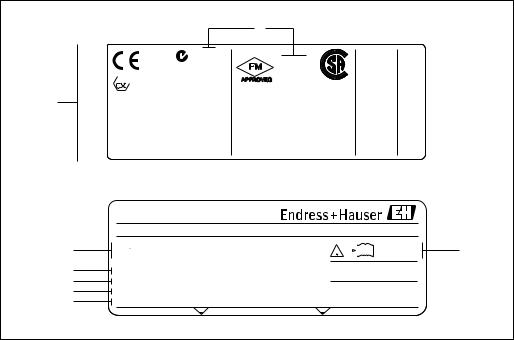
2.1.1Nameplate of the transmitter
|
|
|
6 |
7 |
|
PROSONIC FLOW 93 |
|
|
|
1 |
Order Code: |
93PA1-XXXXXXXXXXXX |
IP67 / NEMA/Type 4X |
|
Ser.No.: |
12345678901 |
|
|
|
|
|
|
||
|
TAG No.: |
ABCDEFGHJKLMNPQRST |
|
|
2 |
16-62VDC/20-55VAC |
|
|
|
50-60Hz |
15VA/W |
|
||
|
|
|||
|
|
|
||
3 |
|
|
|
|
4 |
I-OUT (HART), f-OUT |
|
|
|
STATUS-OUT, STATUS-IN |
|
|
||
|
|
|
||
5 |
|
|
|
|
|
i |
|
-20°C (-4°F) <Tamb<+60°C (+140°F) |
|
|
|
|
||
|
|
|
Pat. UK EP 618 680 |
|
|
|
|
Pat. US 5,479,007 |
|
A0001157
Fig. 1: Nameplate specifications for the "Prosonic Flow 93" transmitter (example)
1Order code/serial number: See the specifications on the order confirmation for the meanings of the individual letters and digits
2Power supply/frequency: 16 to 62 V DC / 20 to 55 V AC / 50 to 60 Hz Power consumption: 15 VA / W
3Reserved for additional information
4Available inputs and outputs:
I-OUT (HART): with current output (HART) f-OUT: with pulse/frequency output RELAY: with relay output
STAT-IN: with status input (auxiliary input)
5Reserved for information on special products
6Permitted ambient temperature range
7Degree of protection
Endress+Hauser |
7 |
Identification |
Proline Prosonic Flow 93 |
|
|
2.1.2Nameplate of the sensor
6
8
7
1
2
3
4
5
0044 |
IP68 |
|
N12895 |

 II2G EEx ib IIC T6-T1
II2D Ex ibD 21 T6-T1
DMT 01 ATEX E 064 X
IECEx BVS 06.0... X
 Tamb/Tumg:-40°C..+60°C
FM NEMA
TYPE 6P
APPROVED
Intrinsically safe for CL.I, GP.ABCD CL.II, GP.EFG, CL.III Dust-Ignitionproof for
CL.II, GP. EFG, CL.III For Installation refer to
control dwg. of transmitter
Type/NEMA6p or IP68
Warning: To maintain
4153 Reinach
Switzerland
PROSONIC FLOW P
Order Code: XXXXX-XXXXXXXXXXXX |
2007 |
|
|
|
|
|
|
|
|
|
|
i |
|||||||
Ser.No.: 12345678901 RY |
|
|
|
|
|
|
|
|
|
|
|
||||||||
Type: P-CL-1F-L-B |
|
|
|
|
|
|
CH 1 |
||||||||||||
DN100 - DN4000 |
|
|
|
|
|
|
|||||||||||||
|
|
|
|
|
|
|
|
|
|
|
|
|
|
|
|||||
-40°C (-40°F) ... +80°C (+175°F) |
|
|
|
|
|
|
|
|
|
|
|
|
|
|
|
||||
|
|
|
|
OPEN |
|
|
|
|
|
|
CLOSE |
||||||||
|
|
|
|
|
|
|
|
|
|
||||||||||
|
|
|
|
|
|
|
|
|
|
||||||||||
protectiontheconnector mustbefullyengaged. |
FEK0924 |
XA059D/
06/../....
ENDRESS+HAUSER |
4153Reinach,Switzerland |
9
A0001158
Fig. 2: Nameplate specifications for the "Prosonic Flow P" sensor (example)
1Order code/serial number: See the specifications on the order confirmation for the meanings of the individual letters and digits.
2Sensor type
3Range of nominal diameter: DN 100 to 4000 (4 to 160")
4Max. fluid temperature range: –40 to +80 °C (–40 to +175 °F)
5Reserved for information on special products
6Degree of protection
7Permitted ambient temperature range
8Data on explosion protection
Refer to the specific additional Ex documentation for detailed information.
Please do not hesitate to contact your Endress+Hauser sales office if you have any questions.
8 |
Endress+Hauser |

Proline Prosonic Flow 93 |
Identification |
|
|
2.1.3Nameplate for the connections
See operating manual Betriebsanleitung beachten Observer manuel d'instruction
A: |
active |
|
|
|
2 |
P: |
passive |
|
|
|
|
NO: |
normally open contact |
|
|
3 |
|
|
|||||
NC: normally closed contact |
|
|
|||
|
|
|
|||
1 |
Ser.No.: 12345678912 |
1 |
2 |
|
|
|
|
/21(-) |
/23(-) |
/25(-) |
/27(-) |
||
|
Supply / |
L1/L+ |
||||
4 |
Versorgung / |
N/L- |
20(+) |
22(+) |
24(+) |
26(+) |
|
Tension d'alimentation |
PE |
||||
|
|
Active: 0/4...20mA, RL max. = 700 Ohm
Passive: 4...20mA, max. 30VDC A I-OUT (HART)
(HART: RL.min. = 250 OHM)
|
|
|
|
fmax = 1kHz |
|
|
|
|
|
|
|
|
|
|
||||
|
|
|
|
Active: 24VDC/25mA (max. 250mA/20ms) |
f-OUT |
|
|
|
|
P |
||||||||
|
|
|
|
|
|
|
|
|
|
|||||||||
5 |
|
|
|
Passive: 30VDC, 250mA |
|
|
|
|
|
|
|
|
|
|||||
|
|
|
|
|
|
|
|
|
|
|
|
|
|
|
|
|
|
|
|
|
|
Passive: 30VDC, 250mA |
|
|
|
|
|
|
X |
||||||||
|
|
|
|
|
|
|
|
|
|
|||||||||
|
|
|
|
|
|
|
|
|
|
STATUS-OUT |
|
|
|
|||||
|
|
|
|
|
|
|
|
|
|
|
|
|
|
|
|
|||
|
|
|
|
|
|
|
|
|
|
|
|
|
|
|
|
|
|
|
|
|
|
|
3...30VDC, Ri = 5kOhm |
|
|
|
|
|
|
X |
|||||||
|
|
|
|
|
|
|
|
|
|
STATUS-IN |
|
|
|
|||||
|
|
|
|
|
|
|
|
|
|
|
|
|
|
|
|
|||
|
|
|
|
|
|
|
|
|
|
|
|
|
|
|
||||
|
|
|
Ex-works / ab-Werk / réglages usine |
Update 1 |
|
Update 2 |
||||||||||||
6 |
|
|
|
|
Device SW: |
XX.XX.XX (WEA) |
|
|
|
|
|
|
|
|
|
|||
|
|
|
|
|
|
|
|
|
|
|
|
|
||||||
|
|
|
|
|
|
|
|
|
|
|
|
|
||||||
7 |
|
|
|
Communication: |
XXXXXXXXXX |
|
|
|
|
|
|
|
|
|
||||
|
|
|
|
|
|
|
|
|
|
|
|
|||||||
8 |
|
|
|
|
|
Drivers: |
ID xxxx (HEX) |
|
|
|
|
|
|
|
|
|
||
|
|
|
|
|
|
|
|
|
|
|
|
|
|
|||||
9 |
|
|
|
|
|
|
Date: DD.MMM.YYYY |
|
|
|
|
|
|
|
|
|
||
|
|
|
|
|
|
|
|
|
|
|
|
|
|
|
||||
|
|
|
|
|
|
|
|
|
|
|
319475-00XX |
|
|
|
|
|
|
|
|
|
|
|
|
|
|
|
|
|
|
|
|
|
|
|
|
|
|
|
|
|
|
|
|
|
|
|
|
|
|
|
|
|
|
|
|
|
10
A0000963
Fig. 3: Nameplate specifications for Proline transmitter (example)
1Serial number
2Possible configuration of the current input
3Possible configuration of the relay contacts
4Terminal assignment, cable for power supply: 85 to 260 V AC, 20 to 55 V AC, 16 to 62 V DC Terminal No. 1: L1 for AC, L+ for DC
Terminal No. 2: N for AC, L- for DC
5Signals present at the inputs and outputs, possible configurations and terminal assignment (20 to 27), see also "Electrical values of the inputs/outputs"
6Version of device software currently installed
7Installed communication mode e.g.: HART, PROFIBUS PA, etc.
8Information on current communication software (Device Revision and Device Description), e.g.: Dev. 01 / DD 01 for HART
9Date of installation
10Current updates to the information listed in Points 6 to 9
Endress+Hauser |
9 |
Identification |
Proline Prosonic Flow 93 |
|
|
2.2Certificates and approvals
The devices are designed in accordance with good engineering practice to meet state-of-the-art safety requirements, have been tested, and left the factory in a condition in which they are safe to operate.
The devices comply with the applicable standards and regulations in accordance with EN 61010-1 "Safety requirements for electrical equipment for measurement, control and laboratory use" and with the EMC requirements of IEC/EN 61326.
The measuring system described in these Operating Instructions thus complies with the statutory requirements of the EC Directives. Endress+Hauser confirms successful testing of the device by affixing to it the CE mark.
The measuring system complies with the EMC requirements of the "Australian Communications and Media Authority (ACMA)".
2.3Registered trademarks
HART ®
Registered trademark of HART Communication Foundation, Austin, USA
HistoROM™, T-DAT™, F-CHIP®, FieldCare®, Fieldcheck®, FieldXpert™, Applicator®
Registered or registration-pending trademarks of Endress+Hauser Flowtec AG, Reinach, CH
10 |
Endress+Hauser |
Proline Prosonic Flow 93 |
Installation |
|
|
3 Installation
3.1Incoming acceptance, transport and storage
3.1.1Incoming acceptance
On receipt of the goods, check the following points:
•Check the packaging and the contents for damage.
•Check the shipment, make sure nothing is missing and that the scope of supply matches your order.
3.1.2Transport
The devices must be transported in the container supplied when transporting them to the measuring point.
3.1.3Storage
•Pack the measuring device in such a way as to protect it reliably against impact for storage (and transportation). The original packaging provides optimum protection.
•The storage temperature corresponds to the ambient temperature range of the transmitter, the sensors and the corresponding sensor cables ( ä 119).
•The measuring device must be protected against direct sunlight during storage in order to avoid unacceptably high surface temperatures.
3.2Installation conditions
3.2.1Dimensions
The dimensions and lengths of the sensor and transmitter are provided in the separate "Technical
Information" document on the device in question. This can be downloaded as a PDF file from
www.endress.com.
A list of the "Technical Information" documents available is provided on ä 130.
3.2.2Mounting location
Correct flow measurement is possible only if a pipe is full. Entrained air or gas bubbles forming in the pipe can result in an increase in measuring errors.
Avoid the following locations in the pipe installation:
•Highest point of a pipeline. Risk of air accumulating.
•Directly upstream of a free pipe outlet in a vertical pipeline.
A0001103
Fig. 4: Mounting location
Endress+Hauser |
11 |

Installation |
Proline Prosonic Flow 93 |
|
|
3.2.3Orientation
Vertical orientation
We recommend the sensor be mounted where there is upward direction of flow. With this orientation, entrained solids will sink down and gases will rise away from the sensor when the fluid is stagnant.
Horizontal orientation
We recommend the sensors be mounted within an angle of ±60° to the horizontal (area shaded gray in the graphic). With this orientation, flow measurement is less affected by any gas or air accumulation in the upper area of the pipe or by buildup at the bottom of the pipe.
A |
C |
C |
|
|
B |
A0001105
Fig. 5: Recommended orientation and recommended installation range
AVertical: Recommended installation with vertical/upward direction of flow
BHorizontal: Recommended installation range with horizontal orientation
CRecommended installation range max. 120°
3.2.4Inlet and outlet run
If possible, install the sensor well clear of assemblies such as valves, T-pieces, elbows, etc. If several flow obstructions are installed, the longest inlet or outlet run must be considered. Compliance with the following inlet and outlet runs is required in order to ensure measuring accuracy.
15 x DN |
3 x DN |
15 x DN1 |
3 x DN1 |
|
|
10 x DN2 |
3 x DN2 |
|
|
A |
1 |
20 x DN |
1 |
|
||
2 |
20 x DN |
2 |
|
||
3 |
15 x DN |
3 |
B
20 x DN1 |
20 x DN2 |
20 x DN1 |
15 x DN2 |
15 x DN1 |
10 x DN2 |
A0013845
Fig. 6: Recommended inlet and outlet runs to comply with measuring accuracy specifications
AClamp-on version
BInsertion version
1 = values for single-path version
2 = values for two-path version
1Valve (2/3 open)
2Pump
3Two pipe bends in different directions
12 |
Endress+Hauser |

Proline Prosonic Flow 93 |
Installation |
|
|
3.2.5Sensor selection and arrangement
The sensors can be arranged in two ways:
•Mounting arrangement for measurement via one traverse: the sensors are located on opposite sides of the pipe.
•Mounting arrangement for measurement via two traverses: the sensors are located on the same side of the pipe.
A 


 B
B
A0001108
Fig. 7: Sensor mounting arrangement (top view)
AMounting arrangement for measurement via one traverse
BMounting arrangement for measurement via two traverses
The number of traverses required depends on the sensor type, the nominal diameter and the thickness of the pipe wall. We recommend the following types of mounting:
Sensor Type |
Nominal Diameter |
Sensor Frequency |
Sensor ID |
Type of Mounting 1) |
||
|
DN 15 to 65 (½ to 2½") |
6 |
MHz |
P-CL-6F* |
2 traverses 5) |
|
|
DN 50 to 65 (2 to 2½") |
2 |
MHz |
P-CL-6F* |
2 (or 1) traverses |
|
|
P-CL-2F* |
|||||
|
|
|
|
|
||
|
|
|
|
|
||
|
DN 80 (3") |
2 MHz |
P-CL-2F* |
2 traverses |
||
Prosonic Flow P |
|
|
|
|
|
|
DN 100 to 300 (4 to 12") |
2 |
MHz (or 1 MHz) |
P-CL-2F* |
2 traverses |
||
|
P-CL-1F* |
|||||
|
|
|
|
|
||
|
|
|
|
|
|
|
|
DN 300 to 600 (12 to 24") |
1 |
MHz (or 2 MHz) |
P-CL-1F* |
2 traverses |
|
|
P-CL-2F* |
|||||
|
|
|
|
|
||
|
|
|
|
|
|
|
|
DN 650 to 4000 (26 to 160") |
1 |
MHz |
P-CL-1F* |
1 traverse |
|
|
|
|
|
|
|
|
|
DN 15 to 65 (½ to 2½") |
6 |
MHz |
W-CL-6F* |
2 traverses 5) |
|
|
DN 50 to 65 (2 to 2½") |
2 |
MHz |
W-CL-2F* |
2 (or 1) traverses 2) |
|
|
DN 80 (3") |
2 MHz |
W-CL-2F* |
2 traverses |
||
|
|
|
|
|
|
|
Prosonic Flow W |
DN 100 to 300 (4 to 12") |
2 |
MHz (or 1 MHz) |
W-CL-2F* |
2 traverses 3) |
|
W-CL-1F* |
||||||
|
|
|
|
|
||
|
|
|
|
|
|
|
|
DN 300 to 600 (12 to 24") |
1 |
MHz (or 2 MHz) |
W-CL-1F* |
2 traverses 3) |
|
|
W-CL-2F* |
|||||
|
|
|
|
|
||
|
|
|
|
|
|
|
|
DN 650 to 4000 (26 to 160") |
1 |
MHz (or 0.5 MHz) |
W-CL-1F* |
1 traverse 3) |
|
|
W-CL-05F* |
|||||
|
|
|
|
|
||
|
|
|
|
|
|
|
1)The installation of clamp-on sensors is principally recommended in the 2 traverse type installation. This type of installation allows the easiest and most comfortable type of mounting and means that a system can also be mounted even if the pipe can only be accessed from one side. However, in certain applications a 1 traverse installation may be preferred. These include:
•Certain plastic pipes with wall thickness > 4 mm (0.16")
•Pipes made of composite materials such as GRP
•Lined pipes
•Applications with fluids with high acoustic damping
2)If the pipe nominal diameter is small (DN 65 / 2½" and smaller), the sensor spacing with Prosonic Flow W can be too small for two traverse installation. In this case, the 1 traverse type of installation must be used.
3)0.5 MHz sensors are also recommended for applications with composite material pipes such as GRP and may be recommended for certain lined pipes, pipes with wall thickness > 10 mm (0.4"), or applications with media with high acoustic damping. In addition, for these applications we principally recommend mounting the W sensors in
a 1 traverse configuration.
4)Insertion W sensors are mounted in a 1 traverse configuration ä 45.
5)6 MHz sensors for applications where flow velocity 10m/s (32.8Hz/s)
Endress+Hauser |
13 |

Installation |
Proline Prosonic Flow 93 |
|
|
3.3Two-channel operation
The transmitter is able to operate two independent measuring channels (measuring channel 1 and measuring channel 2). A pair of sensors is connected per measuring channel. Both measuring channels operate independently of one another and are supported by the transmitter to an equal extent.
Two-channel operation can be used for the following measurements:
•Two-channel measurement = flow measurement at two separate measuring points
•Two-path measurement = redundant flow measurement at one measuring point
3.3.1Two-channel measurement
The flow is measured at two separate measuring points in the case of two-channel measurement.
The measured values of the two measuring channels can be processed and displayed differently.
The following measured values can be output for two-channel measurement:
•Individual measured values per measuring channel (output independently of one another)
•The difference between the two measured values
•The sum of the two measured values
The two measuring channels can be configured individually. This makes it possible to independently configure and select the display, outputs, sensor type and type of installation.
A |
B |
A0001159
Fig. 8: Two-channel measurement: example of arranging sensor pairs at two separate measuring points
AMeasuring channel 1: mounting the sensor pair for measurement via two traverses
BMeasuring channel 2: mounting the sensor pair for measurement via one traverse
14 |
Endress+Hauser |

Proline Prosonic Flow 93 |
Installation |
|
|
3.3.2Two-path measurement
The flow is measured redundantly at one measuring point in the case of two-path measurement.
The measured values of the two measuring channels can be processed and displayed differently. The following measured values can be output for two-path measurement:
•Individual measured values per measuring channel (output independently of one another)
•The average of the two measured values.
The "Averaging" function generally provides you with a more stable measured value. The function is thus suitable for measurements under conditions that are not ideal (e.g. short inlet runs).
The two measuring channels can be configured individually. This makes it possible to independently configure and select the display, outputs, sensor type and type of installation.
It is generally not necessary to individually configure the two measuring channels in the case of twopath measurement. However, in certain situations individual channel configuration can be used to balance out application-specific asymmetries.
A |
B |
|
A0001160 |
Fig. 9: Two-path measurement: examples of arranging sensor pairs at one measuring point
AMeasuring channel 1 and measuring channel 2: mounting the two sensor pairs for one measurement per pair via two traverses
BMeasuring channel 1 and measuring channel 2: mounting the two sensor pairs for one measurement per pair via one traverse
Endress+Hauser |
15 |

Installation |
Proline Prosonic Flow 93 |
|
|
3.4Preparatory steps prior to installation
Depending on the conditions specific to the measuring point (e.g. clamp-on, number of traverses, fluid, etc.), a number of preparatory steps have to be taken before actually installing the sensors:
1.Determination of the values for the necessary installation distances based on the conditions specific to the measuring point. A number of methods are available for determining the values:
–Local operation of the device
–FieldCare (operating program), connect a notebook to the transmitter
–Applicator (software), online on the Endress+Hauser Internet site
2.Mechanical preparation of the clamp-on retainers for the sensors:
–Premount the strapping bands (DN 50 to 200 / 2 to 8") or (DN 250 to 4000 / 10 to 160")
–Fix the welded bolts
3.5Determining the necessary installation distances
The installation distances that have to be maintained depend on:
•The type of sensor: P or W (DN 50 to 4000 / 2 to 160"), P or W (DN 15 to 65 / ½ to 2½")
•Type of mounting:
–Clamp-on with strapping band or welded bolt
–Insertion version, installation in the pipe
•Number of traverses or single-path/dual-path version
3.5.1Installation distances for Prosonic Flow P or W clamp-on
|
|
DN 50 to 4000 (2 to 160") |
|
|
DN 15 to 65 (½ to 2½") |
||
Clamp-on |
|
Clamp-on |
Clamp-on |
||||
|
|||||||
Strapping band |
|
Welded bolts |
Strapping band |
||||
1 traverse |
|
2 traverses |
|
1 traverse |
|
2 traverses |
2 traverses |
|
|
|
|||||
|
|
|
|
|
|
|
|
SENSOR DISTANCE |
|
SENSOR DISTANCE |
|
SENSOR DISTANCE |
|
SENSOR DISTANCE |
SENSOR DISTANCE |
|
|
|
|
|
|
|
|
WIRE LENGTH |
|
POSITION SENSOR |
|
WIRE LENGTH |
|
POSITION SENSOR |
– |
|
|
|
|
|
|
|
|
3.5.2Installation distances for Prosonic Flow W Insertion
DN 200 to 4000 (8 to 160")
Insertion version
Single-path |
Dual-path |
|
|
SENSOR |
SENSOR |
DISTANCE |
DISTANCE |
|
|
PATH LENGTH |
ARC LENGTH |
|
|
16 |
Endress+Hauser |
Proline Prosonic Flow 93 |
Installation |
|
|
3.6Determining values for installation distances
3.6.1Determining installation distances via local operation
Perform the following steps to determine the installation distances:
1.Mount the wall-mount housing.
2.Connect the power supply.
3.Switch on the measuring device.
4.Run the "Sensor Installation" Quick Setup menu.
Installing the wall-mount transmitter housing
There are various ways of installing the wall-mount housing:
•Direct wall mounting
•Panel mounting (with separate mounting kit, accessories) ä 101
•Pipe mounting (with separate mounting kit, accessories) ä 101
"Caution!
•Make sure that the permitted operating temperature range (-20 to +60 °C / –4 to +140 °F) is not exceeded at the mounting location. Install the device in a shady location. Avoid direct sunlight.
•Always install the wall-mount housing in such a way that the cable entries are pointing down.
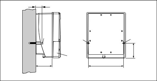
Direct wall mounting
1.Drill the holes ä 17.
2.Remove the cover of the connection compartment (a).
3.Push the two securing screws (b) through the appropriate bores (c) in the housing.
–Securing screws (M6): max. Ø 6.5 mm (0.26")
–Screw head: max. Ø 10.5 mm (0.41")
4.Secure the transmitter housing to the wall as indicated.
5.Screw the cover of the connection compartment (a) firmly onto the housing.
35 (1.38)
b |
c |
c |
|
a |
81.5(3.2) |
90 (3.54) |
192 (7.56) |
mm (inch)
A0001130
Fig. 10: Direct wall mounting
Endress+Hauser |
17 |
Installation |
Proline Prosonic Flow 93 |
|
|
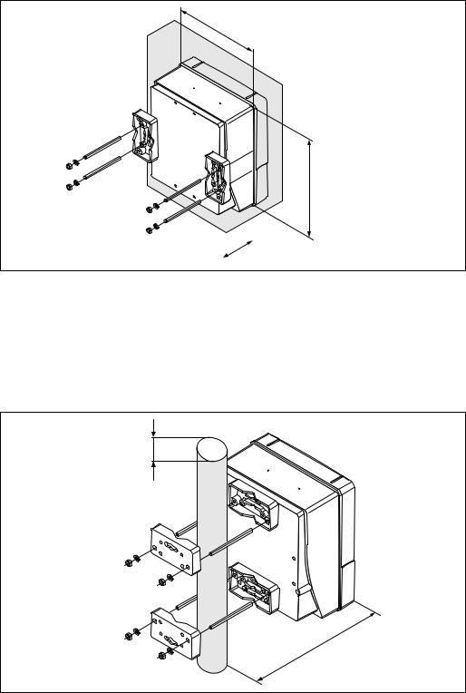
Panel mounting
1.Prepare the opening in the panel ä 18.
2.Slide the housing into the panel cutout from the front.
3.Screw the retainers onto the wall-mount housing.
4.Screw the threaded rods into the retainers and tighten until the housing is solidly seated on the panel wall. Tighten the counter nuts. No further support is necessary.
+0.5 (+0.019)
210 (8.27) –0.5 (–0.019)
+0.5 (+0.019) 245 (9.65)–0.5 (–0.019)
|
|
|
mm (inch) |
~110 (~4.33) |
|
|
|
|
A0001131
Fig. 11: Panel mounting (wall-mount housing)
Pipe mounting
The assembly should be performed by following the instructions on ä 18.
"Caution!If a warm pipe is used for installation, make sure that the housing temperature does not exceed the max. permitted value of +60 °C (+140 °F).
Ø 20…70 (Ø 0.79…2.75)
~155 (~ 6.1)
mm (inch)
A0001132
Fig. 12: Pipe mounting (wall-mount housing)
18 |
Endress+Hauser |

Proline Prosonic Flow 93 |
Installation |
|
|
Connecting the power supply
#Warning!When connecting Ex-certified devices, please refer to the notes and diagrams in the Ex-specific supplement to these Operating Instructions. Please do not hesitate to contact your Endress+Hauser sales office if you have any questions.
!Note!The measuring device does not have an internal power switch. For this reason, assign the measuring device a switch or power-circuit breaker which can be used to disconnect the power supply line from the power grid.
Connecting the power supply
# Warning!• Risk of electric shock. Switch off the power supply before opening the device. Do not install or wire the device while it is connected to the power supply. Failure to comply with this precaution can result in irreparable damage to the electronics.
•Risk of electric shock. Connect the protective ground to the ground terminal on the housing before the power supply is applied (not required for galvanically isolated power supply).
•Compare the specifications on the nameplate with the local supply voltage and frequency. The national regulations governing the installation of electrical equipment also apply.
1.Remove the cover of the connection compartment from the transmitter housing.
2.Route the power supply cable through the cable entries.
3.Wire the power supply cable.
4.Tighten the cable gland.
5.Screw the connection compartment cover back onto the transmitter housing.
L1 (L+) |
|
N (L-) |
|
|
|
+ – + – + – + – |
|
1 |
2 |
20 2122 2324 2526 27 |
|
|
|
|
|
A
A
|
|
|
|
|
|
|
|
|
|
|
|
|
|
|
|
|
|
|
|
|
|
|
|
|
|
|
|
|
|
|
|
|
|
|
|
|
|
|
|
|
|
|
|
|
|
|
|
|
|
|
|
|
|
|
|
|
|
|
|
|
|
|
|
|
|
|
|
|
|
|
|
|
|
|
|
|
|
|
|
|
|
|
|
|
|
|
|
|
|
|
|
|
|
|
|
|
|
|
|
|
|
|
|
|
|
|
|
|
|
|
|
|
|
|
|
|
|
|
|
|
|
|
|
|
|
|
|
|
|
|
|
|
|
|
|
|
|
|
|
|
|
|
|
|
|
|
|
|
|
|
|
|
|
a |
|
|
|
|
a |
|
a1 |
||||||||
|
|
|
|
|
|
|
|
|
|
|
|
|
|
|
|
|
A0011363
Fig. 13: Connecting the power supply; cable cross-section: max. 2.5 mm (14 AWG)
a Cable for power supply: 85 to 260 V AC, 20 to 55 V AC, 16 to 62 V DC Terminal No. 1: L1 for AC, L+ for DC
Terminal No. 2: N for AC, L- for DC a1 Ground terminal for protective ground
Switching on the measuring device
1.Perform the post-connection check as specified in the checklist ä 65.
2.Switch on the supply voltage for the device. The device performs internal test functions. Various messages appear on the display.
3.Normal measuring mode commences. Various measured value and/or status variables appear on the display (HOME position).
!Note!If startup fails, an appropriate error message is displayed, depending on the cause ä 105.
Endress+Hauser |
19 |
Installation |
Proline Prosonic Flow 93 |
|
|
Running the "Sensor Installation" Quick Setup menu
!Note!• If you are not familiar with the operation of the device ä 66.
•The following section only describes the steps necessary for clamp-on and insertion type of mounting within the "Sensor Installation" Quick Setup.
Running the Quick Setup for clamp-on type of mounting
1.Enter or select installation-specific values or the values specified here.
2.Read off the installation distances necessary for mounting.
Home position |
|
Quick Setup |
|
Setup sensor |
|
|
|
|
|
||
|
|
|
|
|
|
|
|
|
|
|
|
|
|
|
|
|
|
|
|
|
|
|
|
|
|
|
|
|
|
|
|
|
|
|
|
|
|
|
|
|
|
Language |
|
|
|
|
|
|
|
|
|
|
|
|
|
|
|
|
|
|
|
|
CH1 |
Channel |
|
|
|
|
|
||
|
|
|
Clamp-on |
|
|
|
|
|
|
||
|
|
|
Measurement |
|
|
|
|
|
|||
|
|
|
|
|
|
|
|
|
|
|
|
|
|
|
|
|
|
Sensor type |
|
|
|
|
|
|
|
|
|
|
|
|
|
|
|||
|
|
|
1 or 2 |
Sensor configuration |
= |
Number of traverses |
|
||||
|
|
|
|
|
|
|
|
|
|
|
|
|
|
|
|
|
|
Pipe standard |
|
|
|
|
|
|
|
|
|
|
|
|
|
|
|
|
|
|
|
|
|
|
|
Nominal diameter |
|
|
|
|
|
|
|
|
|
|
|
|
|
|
|
|
|
|
|
|
|
|
|
Pipe material |
|
|
|
|
|
|
|
|
|
|
|
|
|
|
|
|
|
|
|
|
|
|
|
Sound velocity pipe |
|
|
|
|
|
|
|
|
|
|
|
|
|
|
|
|
|
|
|
|
|
|
|
Pipe diameter |
|
|
|
|
|
|
|
|
|
|
|
|
|
|
|
|
|
|
|
|
|
|
|
Circumference |
|
|
|
|
|
|
|
|
|
|
|
|
|
|
|
|
|
|
|
|
|
|
|
Wall thickness |
|
|
|
|
|
|
|
|
|
|
|
|
|
|
|
|
|
|
|
|
|
|
|
Liner Material |
|
|
|
|
|
|
|
|
|
|
|
|
|
|
|
|
|
|
|
|
|
|
|
Sound Velocity Liner |
|
|
|
|
|
|
|
|
|
|
|
|
|
|
|
|
|
|
|
|
|
|
|
Liner Thickness |
|
|
|
|
|
|
|
|
|
|
|
|
|
|
|
||
|
|
|
|
|
|
Liquid |
|
Installation |
Installation |
||
|
|
|
|
|
|
|
|
distances for |
distances for |
||
|
|
|
|
|
|
Temperature |
|
||||
|
|
|
|
|
|
|
measurement via |
measurement via |
|||
|
|
|
|
|
|
|
|
||||
|
|
|
|
|
|
|
|
||||
|
|
|
|
|
|
Sound velocity liquid |
|
one traverse: |
two traverses: |
||
|
|
|
|
|
|
|
|
|
|
|
|
|
|
|
|
|
|
|
|
|
|
|
|
|
|
|
|
|
|
Position sensor |
– |
|
|
||
|
|
|
|
|
|
|
|
|
|
|
|
|
|
|
|
|
|
|
|
|
|
|
|
|
|
|
|
|
|
Wire length |
|
|
|
– |
|
|
|
|
|
|
|
|
|
|
|
|
|
|
|
|
|
|
|
|
|
|
|
|
|
|
|
|
|
|
|
Sensor distance |
|
|
|
|
|
|
|
|
|
|
|
|
|
|
|
|
|
|
|
|
|
|
|
|
|
|
|
|
|
|
|
|
No |
|
Other measurement? |
|
|
|
|
|
|
|
|
|
|
|
|
|
|
|
|
|
|
|
|
|
No |
Other channel? |
|
|
|
|
|
||
|
|
|
|
|
|
|
|
|
|
|
|
|
|
|
|
|
|
|
|
|
|
|
|
|
|
|
|
|
|
|
|
|
|
|
|
|
|
|
|
|
|
Setup sensor |
|
|
|
|
|
|
|
|
|
|
|
|
|
|
|
|
|
Subsequent procedure
The sensors can be installed once the installation distances have been determined:
•Prosonic Flow P or W (DN 15 to 65 / ½ to 2½) ä 37
•Prosonic Flow P (DN 50 to 4000 / 2 to 160") ä 37
•Prosonic Flow W ä 41
20 |
Endress+Hauser |
Proline Prosonic Flow 93 |
Installation |
|
|
Running the Quick Setup for insertion type of mounting
1.Enter or select installation-specific values or the values specified here.
2.Read off the installation distances necessary for mounting.
Home position |
|
Quick Setup |
|
Setup sensor |
|
|
|
|
||
|
|
|
|
|
|
|
|
|
|
|
|
|
|
|
|
|
|
|
|
|
|
|
|
|
|
|
|
|
|
|
|
|
|
|
|
|
|
|
Language |
|
|
|
|
|
|
|
|
|
|
|
|
|
|
|
|
|
|
CH1 |
Channel |
|
|
|
|
||
|
|
|
|
|
|
|
|
|
|
|
|
|
|
Insertion |
Measurement |
|
|
|
|
||
|
|
|
|
|
|
|
|
|
|
|
|
|
|
|
|
|
Sensor type |
|
|
|
|
|
|
|
|
|
|
|
|
|
|
|
|
|
|
1 or 2 |
Sensor configuration |
= |
Number of paths |
|
|
||
|
|
|
|
|
|
|
|
|
|
|
|
|
|
|
|
|
Pipe standard |
|
|
|
|
|
|
|
|
|
|
|
|
|
|
|
|
|
|
|
|
|
Nominal diameter |
|
|
|
|
|
|
|
|
|
|
|
|
|
|
|
|
|
|
|
|
|
Pipe diameter |
|
Installation |
|
Installation |
|
|
|
|
|
|
Circumference |
|
distances for |
|
distances for |
|
|
|
|
|
|
|
measurement via |
|
measurement via |
|
|
|
|
|
|
|
|
|
|
||
|
|
|
|
|
|
|
|
|
||
|
|
|
|
|
|
Wall thickness |
|
one path: |
|
two paths: |
|
|
|
|
|
|
|
|
|
|
|
|
|
|
|
|
|
Liner Material |
|
|
|
|
|
|
|
|
|
|
|
|
|
|
|
|
|
|
|
|
|
Sound Velocity Liner |
|
|
|
|
|
|
|
|
|
|
|
|
|
|
|
|
|
|
|
|
|
Liner Thickness |
|
|
|
|
|
|
|
|
|
|
|
|
|
|
|
|
|
|
|
|
|
|
|
|
|
|
|
|
|
|
|
|
Sensor distance |
|
|
|
|
|
|
|
|
|
|
|
|
|
|
|
|
|
|
|
|
|
|
|
|
|
|
|
|
|
|
|
|
Arc length |
– |
|
|
|
|
|
|
|
|
|
|
|
|
|
|
|
|
|
|
|
|
|
|
|
|
|
|
|
|
|
|
|
Path length |
|
|
– |
|
|
|
|
|
|
|
|
|
|
|
|
|
|
|
No |
Other measurement? |
|
|
|
|
||
|
|
|
|
|
|
|
|
|
|
|
|
|
|
No |
Other channel? |
|
|
|
|
||
|
|
|
|
|
|
|
|
|
|
|
|
|
|
|
|
|
|
|
|
|
|
|
|
|
|
|
|
|
|
|
|
|
|
|
|
|
|
|
Setup sensor |
|
|
|
|
|
|
|
|
|
|
|
|
|
|
|
Subsequent procedure
The sensors can be installed once the installation distances have been determined:
• Prosonic Flow W ä 45
Endress+Hauser |
21 |

Installation |
Proline Prosonic Flow 93 |
|
|
3.6.2Determining installation distances via FieldCare
FieldCare is Endress+Hauser’s FDT-based plant asset management tool and allows the configuration and diagnosis of intelligent field devices. The Proline flowmeters are accessed via a service interface or via the service interface FXA193.
FieldCare and the FXA193 service interface can be ordered as accessories ä 101. Perform the following steps to determine the installation distances:
1.Mount the wall-mount housing
2.Connecting the power supply
3.Connecting the PC to the plant asset management tool
4.Switch on the measuring device.
5.Read off the installation distances via FieldCare.
Installing the wall-mount transmitter housing
There are various ways of installing the wall-mount housing:
• Direct wall mounting
Panel mounting (with separate mounting kit, accessories) ä 101 Pipe mounting (with separate mounting kit, accessories) ä 101
"Caution!
•Make sure that the permitted operating temperature range
(-20 to +60 °C / –4 to +140 °F) is not exceeded at the mounting location. Install the device in a shady location. Avoid direct sunlight.
•Always install the wall-mount housing in such a way that the cable entries are pointing down.
Direct wall mounting
1.Drill the holes ä 22.
2.Remove the cover of the connection compartment (a).
3.Push the two securing screws (b) through the appropriate bores (c) in the housing.
–Securing screws (M6): max. Ø 6.5 mm (0.26")
–Screw head: max. Ø 10.5 mm (0.41")
4.Secure the transmitter housing to the wall as indicated.
5.Screw the cover of the connection compartment (a) firmly onto the housing.
35 (1.38)
b |
c |
c |
|
a |
81.5(3.2) |
90 (3.54) |
192 (7.56) |
mm (inch)
A0001130
Fig. 14: Direct wall mounting
22 |
Endress+Hauser |

Proline Prosonic Flow 93 |
Installation |
|
|
Panel mounting
1.Prepare the opening in the panel ä 23.
2.Slide the housing into the panel cutout from the front.
3.Screw the retainers onto the wall-mount housing.
4.Screw the threaded rods into the retainers and tighten until the housing is solidly seated on the panel wall. Tighten the counter nuts. No further support is necessary.
+0.5 (+0.019)
210 (8.27) –0.5 (–0.019)
+0.5 (+0.019) 245 (9.65)–0.5 (–0.019)
|
|
|
mm (inch) |
~110 (~4.33) |
|
|
|
|
A0001131
Fig. 15: Panel mounting (wall-mount housing)
Pipe mounting
The assembly should be performed by following the instructions on ä 23.
"Caution!If a warm pipe is used for installation, make sure that the housing temperature does not exceed the max. permitted value of +60 °C (+140 °F).
Ø 20…70 (Ø 0.79…2.75)
~155 (~ 6.1)
mm (inch)
A0001132
Fig. 16: Pipe mounting (wall-mount housing)
Endress+Hauser |
23 |

Installation |
Proline Prosonic Flow 93 |
|
|
Connecting the power supply
#Warning!When connecting Ex-certified devices, please refer to the notes and diagrams in the Ex-specific supplement to these Operating Instructions. Please do not hesitate to contact your Endress+Hauser sales office if you have any questions.
!Note!The measuring device does not have an internal power switch. For this reason, assign the measuring device a switch or power-circuit breaker which can be used to disconnect the power supply line from the power grid.
Connecting the power supply
# Warning!• Risk of electric shock. Switch off the power supply before opening the device. Do not install or wire the device while it is connected to the power supply. Failure to comply with this precaution can result in irreparable damage to the electronics.
•Risk of electric shock. Connect the protective ground to the ground terminal on the housing before the power supply is applied (not required for galvanically isolated power supply).
•Compare the specifications on the nameplate with the local supply voltage and frequency. The national regulations governing the installation of electrical equipment also apply.
1.Remove the cover of the connection compartment from the transmitter housing.
2.Route the power supply cable through the cable entries.
3.Wire the power supply cable.
4.Tighten the cable gland.
L1 (L+) |
|
N (L-) |
|
|
|
+ – + – + – + – |
|
1 |
2 |
20 2122 2324 2526 27 |
|
|
|
|
|
A
A
|
|
|
|
|
|
|
|
|
|
|
|
|
|
|
|
|
|
|
|
|
|
|
|
|
|
|
|
|
|
|
|
|
|
|
|
|
|
|
|
|
|
|
|
|
|
|
|
|
|
|
|
|
|
|
|
|
|
|
|
|
|
|
|
|
|
|
|
|
|
|
|
|
|
|
|
|
|
|
|
|
|
|
|
|
|
|
|
|
|
|
|
|
|
|
|
|
|
|
|
|
|
|
|
|
|
|
|
|
|
|
|
|
|
|
|
|
|
|
|
|
|
|
|
|
|
|
|
|
|
|
|
|
|
|
|
|
|
|
|
|
|
|
|
|
|
|
|
|
|
|
|
|
|
|
|
|
|
|
|
|
|
|
|
|
|
|
|
|
|
|
|
|
|
|
|
|
|
|
|
|
a |
|
|
|
|
a |
|
a1 |
|||||||||
|
|
|
|
|
|
|
|
|
|
|
|
|
|
|
|
||
A0011363
Fig. 17: Connecting the power supply; cable cross-section: max. 2.5 mm (14 AWG)
aCable for power supply: 85 to 260 V AC, 20 to 55 V AC, 16 to 62 V DC Terminal No. 1: L1 for AC, L+ for DC
Terminal No. 2: N for AC, L- for DC
a1 Ground terminal for protective ground
24 |
Endress+Hauser |
Proline Prosonic Flow 93 |
Installation |
|
|
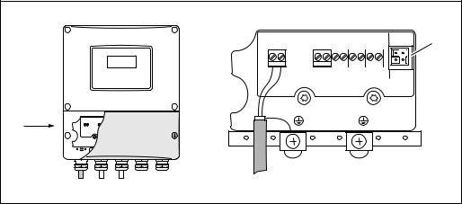
Connecting the PC to the plant asset management tool
A personal computer is connected to the FieldCare plant asset management tool via the service interface FXA 193. The service interface FXA 193 is connected to the service connector of the transmitter.
|
|
+ – + – + – + |
– |
a |
|
1 |
2 |
20 2122 2324 2526 |
27 |
||
|
|||||
A |
|
|
|
|
|
A |
|
|
|
|
|
|
|
|
|
A0011365 |
Fig. 18: Connecting a PC with the FieldCare operating software a Service adapter for connecting service interface FXA193
Switching on the measuring device
1.Perform the post-connection check as specified in the checklist ä 65.
2.Switch on the supply voltage for the device. The device performs internal test functions. Various messages appear on the display.
3.Normal measuring mode commences. Various measured value and/or status variables appear on the display (HOME position).
!Note!If startup fails, an appropriate error message is displayed, depending on the cause ä 105.
Reading off the installation distances via FieldCare
!Note!The following section only illustrates the functions necessary for clamp-on and insertion type of mounting.
Reading off installation distances via FieldCare for clamp-on type of mounting
1.Enter or select installation-specific values or the values specified here.
2.Read off the installation distances necessary for mounting.
Basic function |
|
|
|
|
|
|
|
|
|
|
|
|
|
|
|
Sensor data K1/K2 |
Sensor parameter |
|
|
|
|
|
|
|
|
|
|
|
|
||
Clamp-on |
Measurement |
|
|
|
|
|
|
|
|
Sensor type |
|
|
|
|
|
1 or 2 |
Sensor configuration |
= Number of traverses |
|
|
|
|
|
Endress+Hauser |
25 |

Installation |
Proline Prosonic Flow 93 |
|
|
Basic function |
|
|
|
|
|
|
|
|
|
|
|
|
|
|
|
Process parameter K1/K2 |
Pipe data |
||
|
|
|
|
|
|
|
|
Pipe standard
Nominal diameter
Pipe material
Sound velocity pipe
Circumference
Pipe diameter
Wall thickness
Liner material
Basic function |
|
|
|
|
|
|
|
|
|
|
|
|
|
|
|
Process parameter K1/K2 |
Liquid data |
||
|
|
|
|
|
|
|
|
Liquid
Temperature
Sound velocity liquid
Basic function |
|
|
|
|
|
Process parameter K1/K2 |
|
Sensor parameter |
Position sensor
Wire length
Sensor distance
|
Installation |
Installation |
|
|
distances for |
distances for |
|
|
measurement |
measurement via |
|
|
via one traverse: |
two traverses: |
|
|
– |
|
|
|
|||
|
|
|
|
|
|
– |
|
|
|
||
|
|
|
|
|
|
|
|
|
|
|
|
|
|
|
|
Subsequent procedure
The sensors can be installed once the installation distances have been determined:
•Prosonic Flow P or W (DN 15 to 65 / ½ to 2½") ä 35
•Prosonic Flow P (DN 50 to 4000 / 2 to 160") ä 37
•Prosonic Flow W (Clamp-on) ä 41
26 |
Endress+Hauser |
Proline Prosonic Flow 93 |
Installation |
|
|
Reading off installation distances via FieldCare for insertion type of mounting
1.Enter or select installation-specific values or the values specified here.
2.Read off the installation distances necessary for mounting.
Basic function |
|
|
|
|
|
|
|
|
|
|
|
|
|
|
|
|
|
|
|
|
|
|
|
|
|
|
|
|
|
|
|
Sensor data K1/K2 |
Sensor parameter |
|
|
|
|
||
|
|
|
|
|
|
|
|
|
|
|
|
|
|
|
|
|
|
|
|
|
|
|
|
Insertion |
|
Measurement |
|
|
|
|
|
|
|
|
|
|
|
|
|
|
|
|
Sensor type |
|
|
|
|
|
|
|
|
|
|
|
|
Single-path or dual-path |
Sensor configuration |
= |
Number of paths |
|
|
||
|
|
|
|
|
|
|
|
|
|
|
|
|
|
|
|
Basic function |
|
|
|
|
|
|
|
|
|
|
|
|
|
|
|
|
|
|
|
|
|
|
|
|
|
|
|
|
|
|
|
Process parameter K1/K2 |
Pipe data |
|
|
|
|
||
|
|
|
|
|
|
|
|
|
|
|
|
|
|
|
|
|
|
|
|
|
|
|
|
|
|
|
Pipe standard |
|
|
|
|
|
|
|
|
|
|
|
|
|
|
|
Nominal diameter |
|
|
|
|
|
|
|
|
|
|
|
|
|
|
|
Circumference |
|
|
|
|
|
|
|
|
|
|
|
|
|
|
|
Pipe diameter |
|
|
|
|
|
|
|
|
|
|
|
|
|
|
|
Wall thickness |
|
|
|
|
|
|
|
|
|
|
|
|
|
|
|
|
|
|
|
|
Basic function |
|
|
|
|
|
|
|
|
|
|
|
|
|
|
|
|
|
|
|
|
Installation |
|
Installation |
|
|
|
|
|
|
||
|
|
|
|
distances for |
|
distances for |
|
Process parameter K1/K2 |
Sensor parameter |
|
|
||||
|
measurement |
|
measurement via |
||||
|
|
|
|
|
|
||
|
|
|
|
|
|
||
|
|
|
|
via one traverse: |
|
two traverses: |
|
|
|
|
|
|
|
|
|
|
|
|
Sensor distance |
|
|
|
|
|
|
|
|
|
|
|
|
|
|
|
|
|
|
|
|
|
|
|
Arc length |
– |
|
|
|
|
|
|
|
|
|
|
|
|
|
|
|
|
|
|
|
|
|
|
Path length |
|
|
– |
|
|
|
|
|
|
|
|
|
Subsequent procedure
The sensors can be installed once the installation distances have been determined:
• Prosonic Flow W ä 45.
Endress+Hauser |
27 |
Installation |
Proline Prosonic Flow 93 |
|
|
3.6.3Determining installation distances via Applicator
Applicator is a software application for selecting and planning flowmeters. The installation distances required for installation can be determined without having to commision the transmitter beforehand.
Applicator is available:
•On a CD-ROM for installation on a local PC ä 104.
•Via the Internet for direct online entry www.endress.com select country.
On the Internet site, select Instruments Flow Tooling Applicator. In the "Applicator Sizing Flow" field, select the "Start Applicator Sizing Flow online" link.
Determining installation distances for clamp-on, measuring via one traverse
Determine the installation distances required via Applicator:
•Select the fluid.
•Select the device (e.g. 93P Clamp-on).
•Enter or select measuring point-specific values.
•Select the number of traverses: 1
•Read off the necessary installation distances:
–Wire length: __________
–Sensor distance: __________
Subsequent procedure
The sensors can be installed once the installation distances have been determined:
•Prosonic Flow P (DN 50 to 4000 / 2 to 160") ä 37
•Prosonic Flow W ä 41.
Determining installation distances for clamp-on, measuring via two traverses
Determine the installation distances required via Applicator:
•Select the fluid.
•Select the device (e.g. 93P Clamp-on).
•Enter or select measuring point-specific values.
•Select the number of traverses: 2
•Read off the necessary installation distances:
–Sensor position: __________
–Sensor distance: __________
Subsequent procedure
The sensors can be installed once the installation distances have been determined:
•Prosonic Flow P or W (DN 15 to 65 / ½ to 2½") ä 39
•Prosonic Flow P (DN 50 to 4000 / 2 to 160") ä 39
•Prosonic Flow W ä 43.
Determining installation distances for insertion version, single-path measurement
Determine the installation distances required via Applicator:
•Select the fluid.
•Select the device (e.g. 93W Insert 1Ch).
•Enter or select measuring point-specific values.
•Read off the necessary installation distance:
– Sensor distance: __________
Subsequent procedure
The sensors can be installed once the installation distances have been determined:
• Prosonic Flow W ä 46.
28 |
Endress+Hauser |
Proline Prosonic Flow 93 |
Installation |
|
|
Determining installation distances for insertion version, dual-path measurement
Determine the installation distances required via Applicator:
•Select the fluid.
•Select the device (e.g. 93W Insert 2Ch).
•Enter or select measuring point-specific values.
•Read off the necessary installation distances:
–Sensor distance: __________
–Arc length: __________
Subsequent procedure
The sensors can be installed once the installation distances have been determined:
• Prosonic Flow W ä 41.
Endress+Hauser |
29 |

Installation |
Proline Prosonic Flow 93 |
|
|
3.7Mechanical preparation
The way in which the sensors are secured differs on account of the pipe nominal diameter and the sensor type. Depending on the type of sensor, users also have the option of securing the sensors with strapping bands or screws such that they can be later removed, or permanently fixing the sensors in place with welded bolts or welded retainers.
Overview of possible ways to secure the various sensors:
Prosonic Flow |
For the measuring range |
Pipe nominal |
Secured by |
|
|
|
diameter |
|
|
93W/93P |
DN 15 to 65 |
DN 32 (1¼") |
Sensor holder with U-shaped screws |
ä 30 |
|
(½ to 2½") |
|
|
|
|
DN 32 (1¼") |
Sensor holder with strapping bands |
ä 31 |
|
|
|
|||
|
|
|
|
|
93P |
DN 50 to 4000 |
DN 200 (8") |
Strapping bands (medium nominal diameters) |
ä 32 |
|
(2 to 160") |
|
|
|
|
|
Welded bolts |
ä 34 |
|
|
|
|
||
|
|
|
|
|
|
|
DN 200 (8") |
Strapping bands (large nominal diameters) |
ä 33 |
|
|
|
|
|
|
|
|
Welded bolts |
ä 34 |
|
|
|
|
|
93W |
DN 50 to 4000 |
DN 200 (8") |
Strapping bands (medium nominal diameters) |
ä 32 |
|
(2 to 160") |
|
|
|
|
|
Welded bolts |
ä 34 |
|
|
|
|
||
|
|
|
|
|
|
|
DN 200 (8") |
Strapping bands (large nominal diameters) |
ä 33 |
|
|
|
|
|
|
|
|
Welded bolts |
ä 31 |
|
|
|
|
|
|
|
|
Insertion version |
ä 45 |
|
|
|
|
|
3.7.1Mounting the sensor holder with U-shaped screws
For mounting on a pipe with a nominal diameter of DN 32 (1¼")
For sensors: Prosonic Flow 93W or P (DN 15 to 65 / ½ to 2½")
Procedure
1.Disconnect the sensor from the sensor holder.
2.Position the sensor holder on the pipe.
3.Put the U-shaped screws through the sensor holder and slightly lubricate the thread.
4.Screw nuts onto the U-shaped screws.
5.Set the holder to the exact position and tighten the nuts evenly.
# Warning!
Risk of damaging plastic or glass pipes if the nuts of the U-shaped screws are tightened too much! The use of a metal half-shell is recommended (on the opposite side of the sensor) when working with plastic or glass pipes.
!Note!The visible pipe surface "A" must be smooth to ensure good accustic contact.
A
A0011XXXX
Fig. 19: Mounting the Prosonic Flow P or W sensor holder (DN 15 to 65 / ½ to 2½") with U-shaped screws
30 |
Endress+Hauser |
Loading...