


Proline Prowirl F 200
Table of contents
 Loading...
Products Solutions Services
Operating Instructions
Proline Prowirl F 200
HART
Vortex flowmeter
BA01686D/06/EN/02.19
71442767
2019-07-01
Valid as of version
01.03.zz (Device firmware)

Proline Prowirl F 200 HART
2 Endress+Hauser
• Make sure the document is stored in a safe place such that it is always available when
working on or with the device.
• To avoid danger to individuals or the facility, read the "Basic safety instructions" section
carefully, as well as all other safety instructions in the document that are specific to
working procedures.
• The manufacturer reserves the right to modify technical data without prior notice. Your
Endress+Hauser Sales Center will supply you with current information and updates to
these instructions.

Proline Prowirl F 200 HART Table of contents
Endress+Hauser 3
Table of contents
1 About this document ................ 6
1.1 Document function ..................... 6
1.2 Symbols .............................. 6
1.2.1 Safety symbols .................. 6
1.2.2 Electrical symbols ................ 6
1.2.3 Communication symbols ........... 6
1.2.4 Tool symbols .................... 7
1.2.5 Symbols for
certain types of information ......... 7
1.2.6 Symbols in graphics ............... 7
1.3 Documentation ........................ 8
1.3.1 Standard documentation ........... 8
1.3.2 Supplementary device-dependent
documentation .................. 8
1.4 Registered trademarks ................... 8
2 Safety instructions .................. 9
2.1 Requirements for the personnel ............ 9
2.2 Designated use ........................ 9
2.3 Workplace safety ...................... 10
2.4 Operational safety ..................... 10
2.5 Product safety ........................ 10
2.6 IT security ........................... 11
2.7 Device-specific IT security ................ 11
2.7.1 Protecting access via hardware write
protection ..................... 11
2.7.2 Protecting access via a password .... 11
2.7.3 Access via fieldbus ............... 11
3 Product description ................ 12
3.1 Product design ........................ 12
4 Incoming acceptance and product
identification ..................... 14
4.1 Incoming acceptance ................... 14
4.2 Product identification ................... 14
4.2.1 Transmitter nameplate ........... 15
4.2.2 Sensor nameplate ............... 16
4.2.3 Pressure measuring cells nameplate .. 19
4.2.4 Symbols on measuring device ...... 19
5 Storage and transport ............. 20
5.1 Storage conditions ..................... 20
5.2 Transporting the product ................ 20
5.2.1 Measuring devices without lifting
lugs ......................... 20
5.2.2 Measuring devices with lifting lugs .. 21
5.2.3 Transporting with a fork lift ........ 21
5.3 Packaging disposal ..................... 21
6 Installation ....................... 22
6.1 Installation conditions .................. 22
6.1.1 Mounting position ............... 22
6.1.2 Environment and process
requirements .................. 27
6.1.3 Special mounting instructions ...... 28
6.2 Mounting the measuring device ........... 29
6.2.1 Required tools .................. 29
6.2.2 Preparing the measuring device ..... 29
6.2.3 Mounting the sensor ............. 29
6.2.4 Mounting the pressure measuring
unit ......................... 30
6.2.5 Mounting the transmitter of the
remote version ................. 32
6.2.6 Turning the transmitter housing .... 33
6.2.7 Turning the display module ........ 34
6.3 Post-installation check .................. 34
7 Electrical connection .............. 36
7.1 Connection conditions .................. 36
7.1.1 Required tools .................. 36
7.1.2 Connecting cable requirements ..... 36
7.1.3 Connecting cable for remote
version ....................... 37
7.1.4 Terminal assignment ............. 38
7.1.5 Requirements for the supply unit .... 40
7.1.6 Preparing the measuring device ..... 41
7.2 Connecting the measuring device .......... 41
7.2.1 Connecting the compact version ..... 42
7.2.2 Connecting the remote version ..... 43
7.2.3 Connecting the connecting cable for
the pressure measuring cell ........ 48
7.2.4 Ensuring potential equalization ..... 48
7.3 Ensuring the degree of protection .......... 48
7.4 Post-connection check .................. 48
8 Operation options ................. 50
8.1 Overview of operation options ............ 50
8.2 Structure and function of the operating
menu .............................. 51
8.2.1 Structure of the operating menu .... 51
8.2.2 Operating philosophy ............ 52
8.3 Access to the operating menu via the local
display ............................. 53
8.3.1 Operational display .............. 53
8.3.2 Navigation view ................ 54
8.3.3 Editing view ................... 56
8.3.4 Operating elements .............. 58
8.3.5 Opening the context menu ......... 58
8.3.6 Navigating and selecting from list ... 60
8.3.7 Calling the parameter directly ...... 60
8.3.8 Calling up help text .............. 61
8.3.9 Changing the parameters ......... 62

Table of contents Proline Prowirl F 200 HART
4 Endress+Hauser
8.3.10 User roles and related access
authorization .................. 63
8.3.11 Disabling write protection via access
code ......................... 63
8.3.12 Enabling and disabling the keypad
lock ......................... 64
8.4 Access to the operating menu via the
operating tool ........................ 64
8.4.1 Connecting the operating tool ...... 64
8.4.2 Field Xpert SFX350, SFX370 ....... 65
8.4.3 FieldCare ..................... 66
8.4.4 DeviceCare .................... 67
8.4.5 AMS Device Manager ............ 67
8.4.6 SIMATIC PDM .................. 68
8.4.7 Field Communicator 475 .......... 68
9 System integration ................ 69
9.1 Overview of device description files ......... 69
9.1.1 Current version data for the device ... 69
9.1.2 Operating tools ................. 69
9.2 Measured variables via HART protocol ...... 69
9.3 Other settings ........................ 71
10 Commissioning .................... 74
10.1 Function check ....................... 74
10.2 Switching on the measuring device ......... 74
10.3 Setting the operating language ............ 74
10.4 Configuring the measuring device .......... 75
10.4.1 Defining the tag name ............ 75
10.4.2 Setting the system units .......... 76
10.4.3 Selecting and setting the medium ... 80
10.4.4 Configuring the current input ...... 83
10.4.5 Configuring the current output ..... 85
10.4.6 Configuring the pulse/frequency/
switch output .................. 86
10.4.7 Configuring the local display ....... 91
10.4.8 Configuring the output
conditioning ................... 93
10.4.9 Configuring the low flow cut off ..... 93
10.5 Advanced settings ..................... 95
10.5.1 Setting the medium properties ...... 96
10.5.2 Performing external compensation . 109
10.5.3 Carrying out a sensor adjustment ... 111
10.5.4 Configuring the totalizer ......... 114
10.5.5 Carrying out additional display
configurations ................. 115
10.5.6 Configuration management ....... 118
10.5.7 Using parameters for device
administration ................ 119
10.6 Configuration management ............. 119
10.6.1 Function scope of the "Configuration
management" parameter ......... 120
10.7 Simulation .......................... 121
10.8 Protecting settings from unauthorized
access ............................. 123
10.8.1 Write protection via access code ... 123
10.8.2 Write protection via write protection
switch ....................... 124
10.9 Application-specific commissioning ....... 125
10.9.1 Steam application .............. 125
10.9.2 Liquid application .............. 126
10.9.3 Gas applications ............... 127
10.9.4 Calculation of the measured
variables ..................... 130
11 Operation ....................... 135
11.1 Reading the device locking status ......... 135
11.2 Adjusting the operating language ......... 135
11.3 Configuring the display ................ 135
11.4 Reading measured values ............... 135
11.4.1 Process variables ............... 136
11.4.2 "Totalizer" submenu ............. 139
11.4.3 Input values .................. 139
11.4.4 Output values ................. 140
11.5 Adapting the measuring device to the process
conditions .......................... 141
11.6 Performing a totalizer reset ............. 141
11.6.1 Function scope of the "Control
Totalizer" parameter ............ 141
11.6.2 Function scope of the "Reset all
totalizers" parameter ............ 142
11.7 Showing data logging ................. 142
12 Diagnostics and troubleshooting .. 145
12.1 General troubleshooting ................ 145
12.2 Diagnostic information on local display ..... 147
12.2.1 Diagnostic message ............. 147
12.2.2 Calling up remedial measures ..... 149
12.3 Diagnostic information in FieldCare or
DeviceCare ......................... 149
12.3.1 Diagnostic options .............. 149
12.3.2 Calling up remedy information .... 151
12.4 Adapting the diagnostic information ...... 151
12.4.1 Adapting the diagnostic behavior ... 151
12.4.2 Adapting the status signal ........ 152
12.5 Overview of diagnostic information ....... 152
12.5.1 Operating conditions for displaying
the following diagnostics
information .................. 156
12.5.2 Emergency mode in the event of
pressure compensation .......... 156
12.5.3 Emergency mode in event of
temperature compensation ....... 156
12.6 Pending diagnostic events .............. 157
12.7 Diagnostic list ....................... 157
12.8 Event logbook ....................... 158
12.8.1 Reading out the event logbook ..... 158
12.8.2 Filtering the event logbook ....... 158
12.8.3 Overview of information events .... 159
12.9 Resetting the measuring device .......... 160
12.9.1 Function scope of the "Device reset"
parameter .................... 160
12.10 Device information ................... 160
12.11 Firmware history ..................... 162

Proline Prowirl F 200 HART Table of contents
Endress+Hauser 5
13 Maintenance .................... 163
13.1 Maintenance tasks .................... 163
13.1.1 Exterior cleaning ............... 163
13.1.2 Interior cleaning ............... 163
13.1.3 Replacing seals ................ 163
13.1.4 Adjusting the pressure measuring
cell ......................... 163
13.2 Measuring and test equipment ........... 164
13.3 Endress+Hauser services ............... 164
14 Repair ........................... 165
14.1 General notes ....................... 165
14.1.1 Repair and conversion concept ..... 165
14.1.2 Notes for repair and conversion .... 165
14.2 Spare parts ......................... 165
14.3 Endress+Hauser services ............... 166
14.4 Return ............................. 166
14.5 Disposal ........................... 166
14.5.1 Removing the measuring device .... 166
14.5.2 Disposing of the measuring device .. 167
15 Accessories ...................... 168
15.1 Device-specific accessories .............. 168
15.1.1 For the transmitter ............. 168
15.1.2 For the sensor ................. 169
15.2 Communication-specific accessories ....... 169
15.3 Service-specific accessories .............. 170
15.4 System components ................... 171
16 Technical data ................... 172
16.1 Application ......................... 172
16.2 Function and system design ............. 172
16.3 Input .............................. 172
16.4 Output ............................ 179
16.5 Power supply ........................ 182
16.6 Performance characteristics ............. 185
16.7 Installation ......................... 189
16.8 Environment ........................ 189
16.9 Process ............................ 191
16.10 Mechanical construction ............... 193
16.11 Operability ......................... 202
16.12 Certificates and approvals .............. 203
16.13 Application packages .................. 204
16.14 Accessories ......................... 205
16.15 Supplementary documentation ........... 205
Index ................................. 207
About this document Proline Prowirl F 200 HART
6 Endress+Hauser
1 About this document
1.1 Document function
These Operating Instructions contain all the information that is required in various phases
of the life cycle of the device: from product identification, incoming acceptance and
storage, to mounting, connection, operation and commissioning through to
troubleshooting, maintenance and disposal.
1.2 Symbols
1.2.1 Safety symbols
DANGER
This symbol alerts you to a dangerous situation. Failure to avoid this situation will result in
serious or fatal injury.
WARNING
This symbol alerts you to a dangerous situation. Failure to avoid this situation can result in
serious or fatal injury.
CAUTION
This symbol alerts you to a dangerous situation. Failure to avoid this situation can result in
minor or medium injury.
NOTICE
This symbol contains information on procedures and other facts which do not result in
personal injury.
1.2.2 Electrical symbols
Symbol Meaning
Direct current
Alternating current
Direct current and alternating current
Ground connection
A grounded terminal which, as far as the operator is concerned, is grounded via a
grounding system.
Protective Earth (PE)
A terminal which must be connected to ground prior to establishing any other
connections.
The ground terminals are situated inside and outside the device:
• Inner ground terminal: Connects the protectiv earth to the mains supply.
• Outer ground terminal: Connects the device to the plant grounding system.
1.2.3 Communication symbols
Symbol Meaning
Wireless Local Area Network (WLAN)
Communication via a wireless, local network.

Proline Prowirl F 200 HART About this document
Endress+Hauser 7
1.2.4 Tool symbols
Symbol Meaning
Flat blade screwdriver
Allen key
Open-ended wrench
1.2.5 Symbols for certain types of information
Symbol Meaning
Permitted
Procedures, processes or actions that are permitted.
Preferred
Procedures, processes or actions that are preferred.
Forbidden
Procedures, processes or actions that are forbidden.
Tip
Indicates additional information.
Reference to documentation.
A
Reference to page.
Reference to graphic.
Notice or individual step to be observed.
1.
,
2.
,
3.
… Series of steps.
Result of a step.
Help in the event of a problem.
Visual inspection.
1.2.6 Symbols in graphics
Symbol Meaning
1, 2, 3, ... Item numbers
1.
,
2.
,
3.
, … Series of steps
A, B, C, ... Views
A-A, B-B, C-C, ... Sections
-
Hazardous area
.
Safe area (non-hazardous area)
Flow direction

About this document Proline Prowirl F 200 HART
8 Endress+Hauser
1.3 Documentation
For an overview of the scope of the associated Technical Documentation, refer to the
following:
• W@M Device Viewer (www.endress.com/deviceviewer): Enter the serial number
from nameplate
• Endress+Hauser Operations App: Enter the serial number from the nameplate or
scan the 2D matrix code (QR code) on the nameplate
Detailed list of the individual documents along with the documentation code
→ 205
1.3.1 Standard documentation
Document type Purpose and content of the document
Technical Information Planning aid for your device
The document contains all the technical data on the device and provides
an overview of the accessories and other products that can be ordered for
the device.
Sensor Brief Operating Instructions Guides you quickly to the 1st measured value - Part 1
The Sensor Brief Operating Instructions are aimed at specialists with
responsibility for installing the measuring device.
• Incoming acceptance and product identification
• Storage and transport
• Installation
Transmitter Brief Operating
Instructions
Guides you quickly to the 1st measured value - Part 2
The Transmitter Brief Operating Instructions are aimed at specialists with
responsibility for commissioning, configuring and parameterizing the
measuring device (until the first measured value).
• Product description
• Installation
• Electrical connection
• Operation options
• System integration
• Commissioning
• Diagnostic information
Description of Device Parameters Reference for your parameters
The document provides a detailed explanation of each individual
parameter in the Expert operating menu. The description is aimed at
those who work with the device over the entire life cycle and perform
specific configurations.
1.3.2 Supplementary device-dependent documentation
Additional documents are supplied depending on the device version ordered: Always
comply strictly with the instructions in the supplementary documentation. The
supplementary documentation is an integral part of the device documentation.
1.4 Registered trademarks
HART®
Registered trademark of the FieldComm Group, Austin, Texas, USA
KALREZ®, VITON®
Registered trademarks of DuPont Performance Elastomers L.L.C., Wilmington, DE USA
GYLON®
Registered trademark of Garlock Sealing Technologies, Palmyar, NY, USA

Proline Prowirl F 200 HART Safety instructions
Endress+Hauser 9
2 Safety instructions
2.1 Requirements for the personnel
The personnel for installation, commissioning, diagnostics and maintenance must fulfill
the following requirements:
‣
Trained, qualified specialists must have a relevant qualification for this specific function
and task.
‣
Are authorized by the plant owner/operator.
‣
Are familiar with federal/national regulations.
‣
Before starting work, read and understand the instructions in the manual and
supplementary documentation as well as the certificates (depending on the
application).
‣
Follow instructions and comply with basic conditions.
The operating personnel must fulfill the following requirements:
‣
Are instructed and authorized according to the requirements of the task by the facility's
owner-operator.
‣
Follow the instructions in this manual.
2.2 Designated use
Application and media
Depending on the version ordered, the measuring device can also measure potentially
explosive, flammable, poisonous and oxidizing media.
Measuring devices for use in hazardous areas, in hygienic applications or where there is an
increased risk due to process pressure, are labeled accordingly on the nameplate.
To ensure that the measuring device remains in proper condition for the operation time:
‣
Keep within the specified pressure and temperature range.
‣
Only use the measuring device in full compliance with the data on the nameplate and
the general conditions listed in the Operating Instructions and supplementary
documentation.
‣
Based on the nameplate, check whether the ordered device is permitted for the
intended use in the hazardous area (e.g. explosion protection, pressure vessel safety).
‣
Use the measuring device only for media to which the process-wetted materials are
sufficiently resistant.
‣
If the ambient temperature of the measuring device is outside the atmospheric
temperature, it is absolutely essential to comply with the relevant basic conditions as
specified in the device documentation. → 8
‣
Protect the measuring device permanently against corrosion from environmental
influences.
Incorrect use
Non-designated use can compromise safety. The manufacturer is not liable for damage
caused by improper or non-designated use.
L
WARNING
Danger of breakage due to corrosive or abrasive fluids and ambient conditions!
‣
Verify the compatibility of the process fluid with the sensor material.
‣
Ensure the resistance of all fluid-wetted materials in the process.
‣
Keep within the specified pressure and temperature range.

Safety instructions Proline Prowirl F 200 HART
10 Endress+Hauser
NOTICE
Verification for borderline cases:
‣
For special fluids and fluids for cleaning, Endress+Hauser is glad to provide assistance
in verifying the corrosion resistance of fluid-wetted materials, but does not accept any
warranty or liability as minute changes in the temperature, concentration or level of
contamination in the process can alter the corrosion resistance properties.
Residual risks
L
WARNING
The electronics and the medium may cause the surfaces to heat up. This presents a
burn hazard!
‣
For elevated fluid temperatures, ensure protection against contact to prevent burns.
2.3 Workplace safety
For work on and with the device:
‣
Wear the required personal protective equipment according to federal/national
regulations.
For welding work on the piping:
‣
Do not ground the welding unit via the measuring device.
If working on and with the device with wet hands:
‣
Due to the increased risk of electric shock, gloves must be worn.
2.4 Operational safety
Risk of injury.
‣
Operate the device in proper technical condition and fail-safe condition only.
‣
The operator is responsible for interference-free operation of the device.
Conversions to the device
Unauthorized modifications to the device are not permitted and can lead to unforeseeable
dangers.
‣
If, despite this, modifications are required, consult with Endress+Hauser.
Repair
To ensure continued operational safety and reliability,
‣
Carry out repairs on the device only if they are expressly permitted.
‣
Observe federal/national regulations pertaining to repair of an electrical device.
‣
Use original spare parts and accessories from Endress+Hauser only.
2.5 Product safety
This measuring device is designed in accordance with good engineering practice to meet
state-of-the-art safety requirements, has been tested, and left the factory in a condition in
which it is safe to operate.
It meets general safety standards and legal requirements. It also complies with the EU
directives listed in the device-specific EU Declaration of Conformity. Endress+Hauser
confirms this by affixing the CE mark to the device.

Proline Prowirl F 200 HART Safety instructions
Endress+Hauser 11
2.6 IT security
Our warranty is valid only if the device is installed and used as described in the Operating
Instructions. The device is equipped with security mechanisms to protect it against any
inadvertent changes to the settings.
IT security measures, which provide additional protection for the device and associated
data transfer, must be implemented by the operators themselves in line with their security
standards.
2.7 Device-specific IT security
The device offers a range of specific functions to support protective measures on the
operator's side. These functions can be configured by the user and guarantee greater in-
operation safety if used correctly. An overview of the most important functions is provided
in the following section.
2.7.1 Protecting access via hardware write protection
Write access to the device parameters via the local display or operating tool (e.g. FieldCare,
DeviceCare) can be disabled via a write protection switch (DIP switch on the motherboard).
When hardware write protection is enabled, only read access to the parameters is possible.
2.7.2 Protecting access via a password
A password can be used to protect against write access to the device parameters.
This password locks write access to the device parameters via the local display or another
operating tool (e.g. FieldCare, DeviceCare) and, in terms of functionality, is equivalent to
hardware write protection. If the service interface CDI RJ-45 is used, read access is only
possible if the password is entered.
User-specific access code
Write access to the device parameters via the local display or operating tool (e.g. FieldCare,
DeviceCare) can be protected by the modifiable, user-specific access code (→ 123).
When the device is delivered, the device does not have an access code and is equivalent to
0000 (open).
General notes on the use of passwords
• The access code and network key supplied with the device should be changed during
commissioning.
• Follow the general rules for generating a secure password when defining and managing
the access code or network key.
• The user is responsible for the management and careful handling of the access code and
network key.
• For information on configuring the access code or on what to do if you lose the
password, see the "Write protection via access code" section → 123
2.7.3 Access via fieldbus
Cyclic fieldbus communication (read and write, e.g. measured value transmission) with a
higher-order system is not affected by the restrictions mentioned above.

Product description Proline Prowirl F 200 HART
12 Endress+Hauser
3 Product description
The device consists of a transmitter and a sensor.
Two device versions are available:
• Compact version – transmitter and sensor form a mechanical unit.
• Remote version - transmitter and sensor are mounted in separate locations.
3.1 Product design
1 2
3
4
5 6
7
8
9
+
E
–
A0020649
1 Important components of a measuring device
1 Electronics compartment cover
2 Display module
3 Main electronics module
4 Cable glands
5 Transmitter housing (incl. HistoROM)
6 I/O electronics module
7 Terminals (spring loaded terminals, pluggable)
8 Connection compartment cover
9 Sensor
Proline Prowirl F 200 HART Product description
Endress+Hauser 13
1
2
A0034152
2 Versions of pressure measuring unit
1 Order code for "Sensor version", option DA "mass steam"
2 Order code for "Sensor version", option DB "mass gas/liquid"
Incoming acceptance and product identification Proline Prowirl F 200 HART
14 Endress+Hauser
4 Incoming acceptance and product
identification
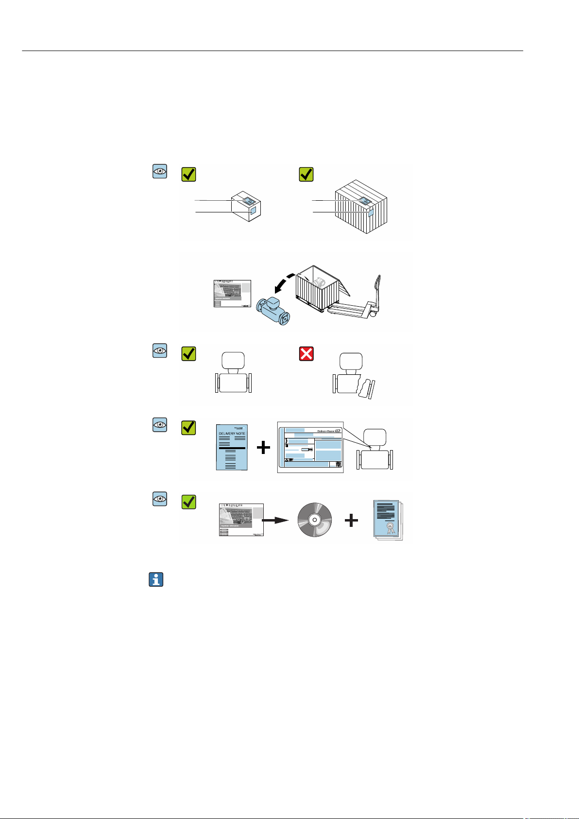
4.1 Incoming acceptance
1
2
1
2
Are the order codes on the
delivery note (1) and the
product sticker (2) identical?
Are the goods undamaged?
Order code:
Ser. no.:
Ext. ord. cd.:
i
i
Date:
Do the nameplate data
match the ordering
information on the delivery
note?
Is the document folder
present with accompanying
documents?
Is the optional CD-ROM with
the Technical
Documentation present?
• If one of the conditions is not satisfied, contact your Endress+Hauser Sales Center.
• Depending on the device version, the CD-ROM might not be part of the delivery!
The Technical Documentation is available via the Internet or via the Endress+Hauser
Operations App, see the "Product identification" section → 15.
4.2 Product identification
The following options are available for identification of the device:
• Nameplate specifications
• Order code with breakdown of the device features on the delivery note
• Enter serial numbers from nameplates in the W@M Device Viewer
(www.endress.com/deviceviewer): All information about the device is displayed.
• Enter the serial number from nameplates in the Endress+Hauser Operations App or scan
the 2-D matrix code (QR code) on the nameplate using the Endress+Hauser Operations
App: All information about the device is displayed.
Proline Prowirl F 200 HART Incoming acceptance and product identification
Endress+Hauser 15
For an overview of the scope of the associated Technical Documentation, refer to the
following:
• The "Additional standard documentation on the device"→ 8 and "Supplementary
device-dependent documentation"→ 8 sections
• The W@M Device Viewer: enter the serial number from the nameplate
(www.endress.com/deviceviewer)
• The Endress+Hauser Operations App: Enter the serial number from the nameplate or
scan the 2-D matrix code (QR code) on the nameplate.
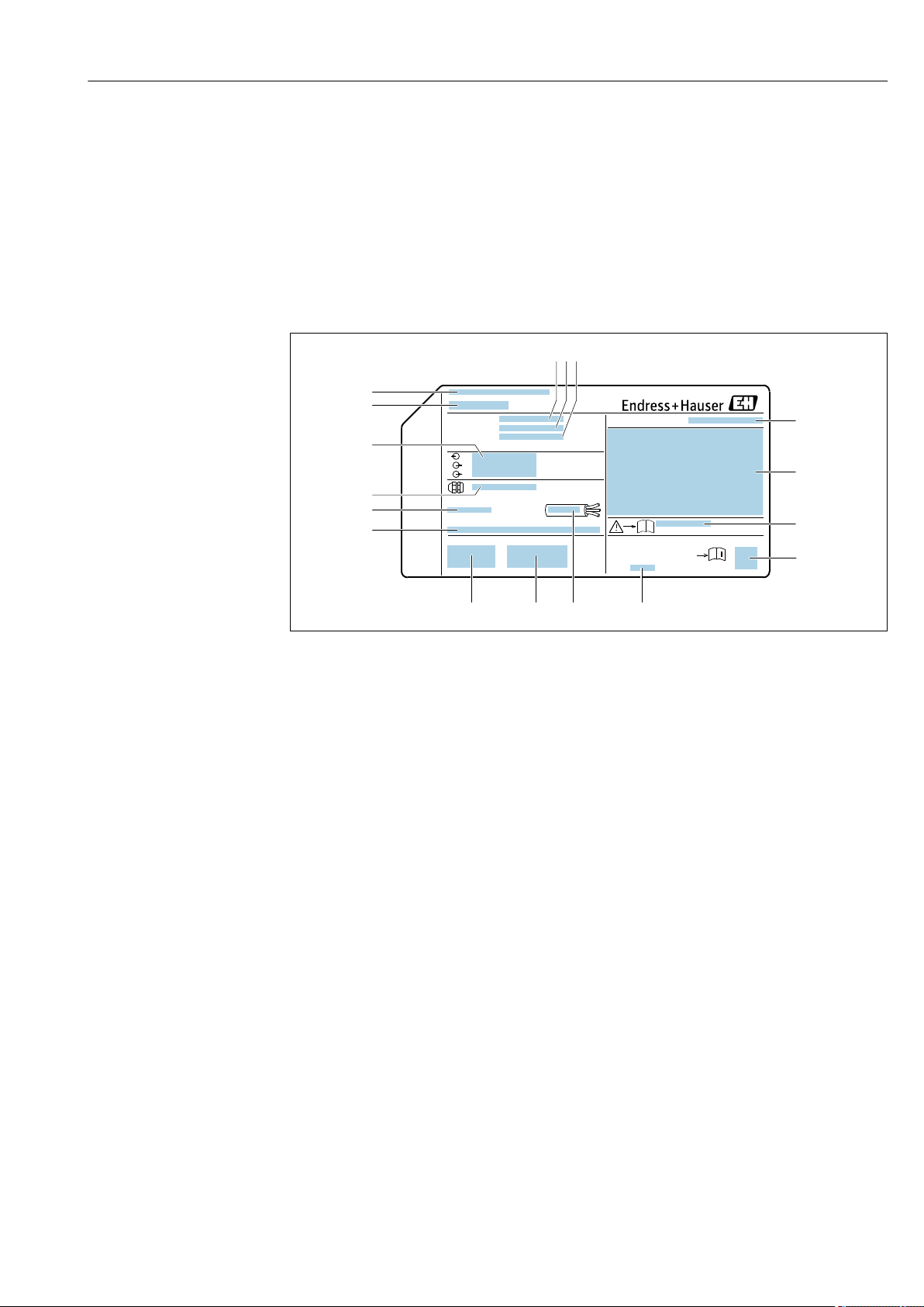
4.2.1 Transmitter nameplate
Order code:
Ext. ord. cd.:
Ser. no.:
Date:
i
i
Patents
322540-0001
1
2
3 4 5
6
7
8
9
10 11
12
14
15
16
17
13
A0032237
3 Example of a transmitter nameplate
1 Manufacturing location
2 Name of the transmitter
3 Order code
4 Serial number (ser. no.)
5 Extended order code (Ext. ord. cd.)
6 Electrical connection data, e.g. available inputs and outputs, supply voltage
7 Type of cable glands
8 Permitted ambient temperature (T
a
)
9 Firmware version (FW) and device revision (Dev.Rev.) from the factory
10 CE mark, C-Tick
11 Additional information on version: certificates, approvals
12 Permitted temperature range for cable
13 Manufacturing date: year-month
14 Degree of protection
15 Approval information for explosion protection
16 Document number of safety-related supplementary documentation
17 2-D matrix code
Incoming acceptance and product identification Proline Prowirl F 200 HART
16 Endress+Hauser
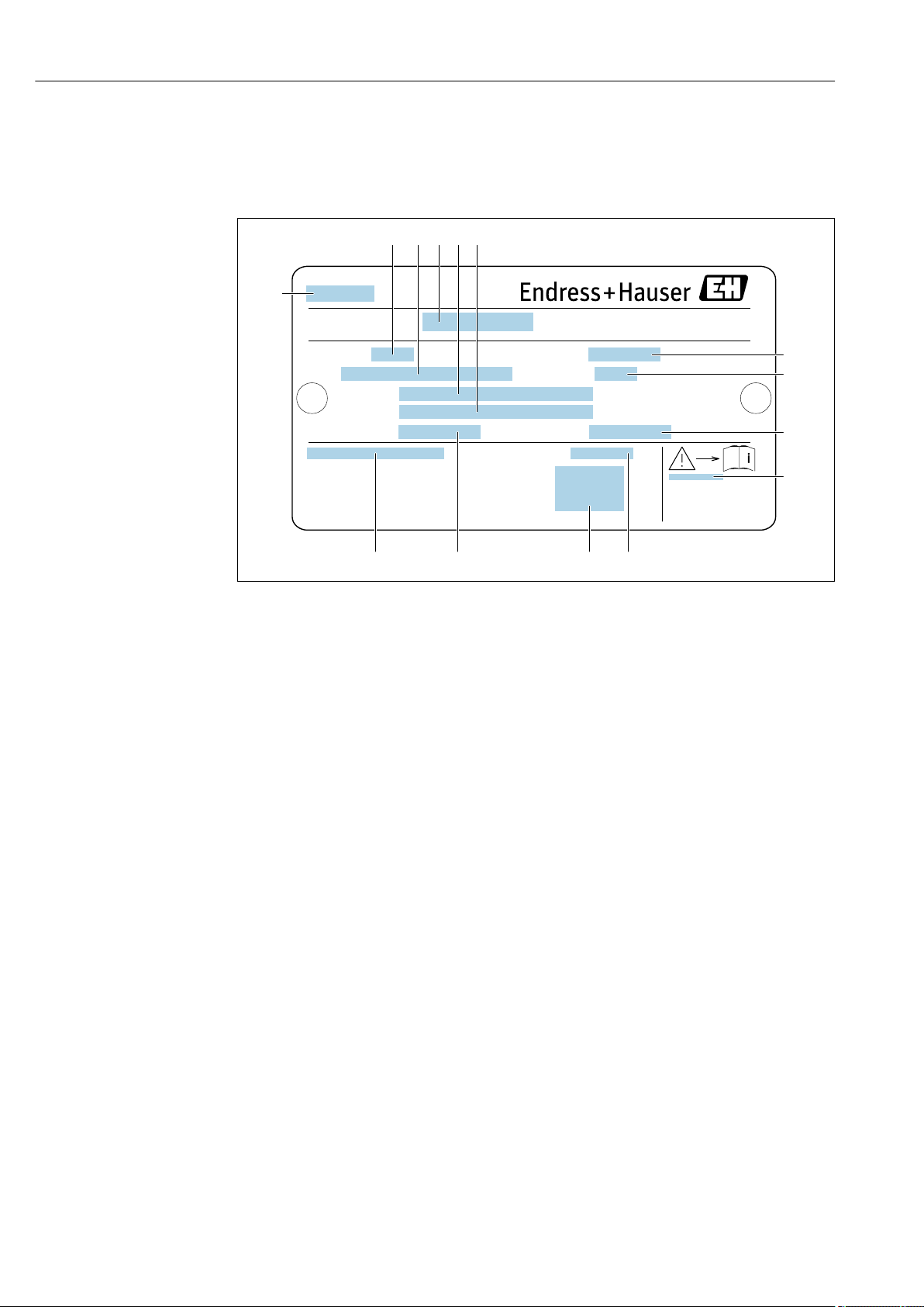
4.2.2 Sensor nameplate
Order code for "Housing" option B "GT18 dual compartment, 316L, compact" and
option K "GT18 dual compartment, 316L, remote"
Ser. no.:
Ptest:
Size:
Materials:
Gasket:
Tm:
Qmax(G):
Ta:
1
2 6
7
8
3
9
10
13 12
4 5
14 11
A0034423
4 Example of a sensor nameplate
1 Name of the sensor
2 Nominal diameter of sensor
3 Flange nominal diameter/nominal pressure
4 Serial number (ser. no.)
5 Measuring tube material
6 Measuring tube material
7 Maximum permitted volume flow (gas/steam): Q
max
→ 173
8 Test pressure of the sensor: OPL→ 192
9 Seal material
10 Document number of safety-related supplementary documentation → 205
11 Ambient temperature range
12 CE mark
13 Medium temperature range
14 Degree of protection

Proline Prowirl F 200 HART Incoming acceptance and product identification
Endress+Hauser 17
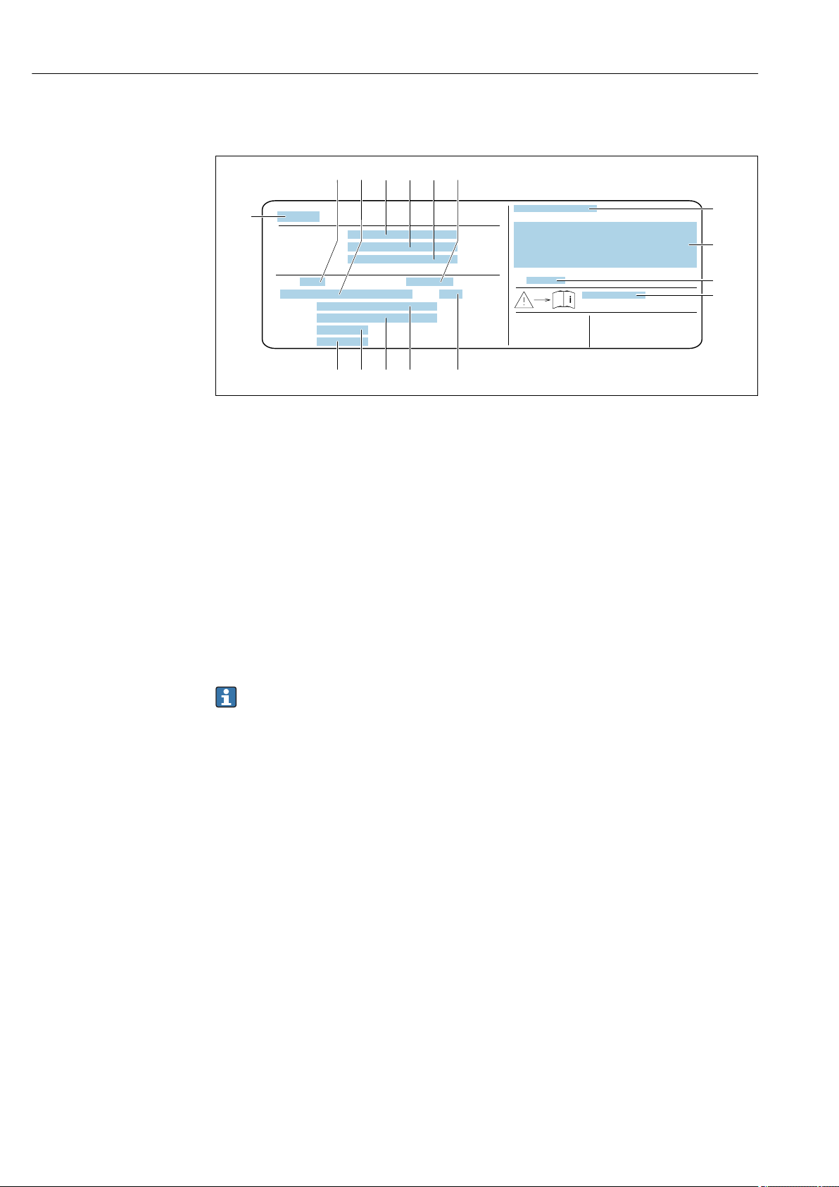
Order code for "Housing" option C "GT20 dual compartment, aluminum, coated,
compact"
Ser. no.:
Ptest:
Size:
Materials:
Tm:
Qmax(G):
Gasket:
Ta:
1
2
5 6 8
7
9
3
4
10
111213
A0034161
5 Example of a sensor nameplate
1 Nominal diameter of sensor
2 Flange nominal diameter/nominal pressure
3 Measuring tube material
4 Measuring tube material
5 Serial number (ser. no.)
6 Maximal permitted volume flow (gas/steam)
7 Test pressure of the sensor
8 Degree of protection
9 Approval information for explosion protection and Pressure Equipment Directive→ 205
10 CE mark
11 Seal material
12 Medium temperature range
13 Ambient temperature range
Incoming acceptance and product identification Proline Prowirl F 200 HART
18 Endress+Hauser
Order code for "Housing" option J "GT20 dual compartment, aluminum, coated,
remote"
Order code:
Ext. ord. cd.:
Ser. no.:
Ptest:
Size:
Ta:
Materials:
Gasket:
Tm:
Qmax(G):
4
1
5
8
12
2
7
9
10
11
13141516
3
6
A0034162
6 Example of a sensor nameplate
1 Name of the sensor
2 Nominal diameter of sensor
3 Flange nominal diameter/nominal pressure
4 Order code
5 Serial number (ser. no.)
6 Extended order code (Ext. ord. cd.)
7 Maximal permitted volume flow (gas/steam)
8 Degree of protection
9 Approval information for explosion protection and Pressure Equipment Directive
10 Ambient temperature range
11 Document number of safety-related supplementary documentation → 205
12 Test pressure of the sensor
13 Measuring tube material
14 Measuring tube material
15 Seal material
16 Medium temperature range
Order code
The measuring device is reordered using the order code.
Extended order code
• The device type (product root) and basic specifications (mandatory features) are
always listed.
• Of the optional specifications (optional features), only the safety and approval-
related specifications are listed (e.g. LA). If other optional specifications are also
ordered, these are indicated collectively using the # placeholder symbol (e.g. #LA#).
• If the ordered optional specifications do not include any safety and approval-related
specifications, they are indicated by the + placeholder symbol (e.g. XXXXXX-ABCDE
+).

Proline Prowirl F 200 HART Incoming acceptance and product identification
Endress+Hauser 19
4.2.3 Pressure measuring cells nameplate
DCP21
1
2
3
4
5
6
7
8
9
Date:
A0034354
7 Example of pressure measuring cell nameplate
1 Manufacturer address
2 Pressure range
3 Maximum permitted pressure
4 Ambient temperature range
5 Serial number or XPD structure
6 Degree of protection
7 CE mark, C-Tick mark
8 QR code
9 Manufacturing date
4.2.4 Symbols on measuring device
Symbol Meaning
WARNING!
This symbol alerts you to a dangerous situation. Failure to avoid this situation can result in serious
or fatal injury.
Reference to documentation
Refers to the corresponding device documentation.
Protective ground connection
A terminal which must be connected to ground prior to establishing any other connections.

Storage and transport Proline Prowirl F 200 HART
20 Endress+Hauser
5 Storage and transport
5.1 Storage conditions
Observe the following notes for storage:
‣
Store in the original packaging to ensure protection from shock.
‣
Do not remove protective covers or protective caps installed on process connections.
They prevent mechanical damage to the sealing surfaces and contamination in the
measuring tube.
‣
Protect from direct sunlight to avoid unacceptably high surface temperatures.
‣
Store in a dry and dust-free place.
‣
Do not store outdoors.
Storage temperature: –50 to +80 °C (–58 to +176 °F)
5.2 Transporting the product
Transport the measuring device to the measuring point in the original packaging.
A0029252
Do not remove protective covers or caps installed on process connections. They
prevent mechanical damage to the sealing surfaces and contamination in the
measuring tube.
5.2.1 Measuring devices without lifting lugs
L
WARNING
Center of gravity of the measuring device is higher than the suspension points of the
webbing slings.
Risk of injury if the measuring device slips.
‣
Secure the measuring device against slipping or turning.
‣
Observe the weight specified on the packaging (stick-on label).
A0029214

Proline Prowirl F 200 HART Storage and transport
Endress+Hauser 21
5.2.2 Measuring devices with lifting lugs
L
CAUTION
Special transportation instructions for devices with lifting lugs
‣
Only use the lifting lugs fitted on the device or flanges to transport the device.
‣
The device must always be secured at two lifting lugs at least.
5.2.3 Transporting with a fork lift
If transporting in wood crates, the floor structure enables the crates to be lifted lengthwise
or at both sides using a forklift.
5.3 Packaging disposal
All packaging materials are environmentally friendly and 100 % recyclable:
• Outer packaging of device
Polymer stretch wrap that complies with EU Directive 2002/95/EC (RoHS)
• Packaging
• Wooden crate treated in accordance with ISPM 15 standard, confirmed by IPPC logo
• Cardboard box in accordance with European packaging guideline 94/62EC,
recyclability confirmed by Resy symbol
• Carrying and securing materials
• Disposable plastic pallet
• Plastic straps
• Plastic adhesive strips
• Filler material
Paper pads
Installation Proline Prowirl F 200 HART
22 Endress+Hauser
6 Installation
6.1 Installation conditions
6.1.1 Mounting position
Mounting location
A0015543
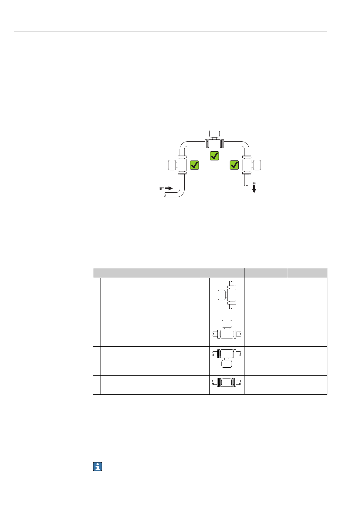
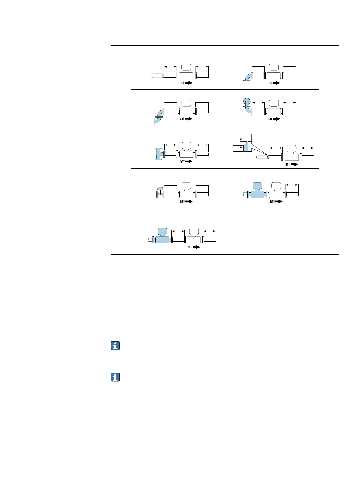
Orientation
The direction of the arrow on the sensor nameplate helps you to install the sensor
according to the flow direction (direction of medium flow through the piping).
Vortex meters require a fully developed flow profile as a prerequisite for correct volume
flow measurement. Therefore, please note the following:
Orientation Compact version Remote version
A Vertical orientation
A0015545
1)
B Horizontal orientation, transmitter head up
A0015589
2) 3)
C Horizontal orientation, transmitter head down
A0015590
4) 5)
D Horizontal orientation, transmitter head at side
A0015592
4)
1) In the case of liquids, there should be upward flow in vertical pipes to avoid partial pipe filling (Fig. A).
Disruption in flow measurement! In the case of vertical orientation and downward flowing liquid, the pipe
always needs to be completely filled to ensure correct liquid flow measurement.
2) Danger of electronics overheating! If the fluid temperature is ≥ 200 °C (392 °F), orientation B is not
permitted for the wafer version (Prowirl D) with nominal diameters of DN 100 (4") and DN 150 (6").
3) In the case of hot media (e.g. steam or fluid temperature (TM) ≥ 200 °C (392 °F): orientation C or D
4) In the case of very cold media (e.g. liquid nitrogen): orientation B or D
5) For "wet steam detection/measurement" option: orientation C
The "mass" sensor version (integrated pressure/temperature measurement) is
available only for measuring devices in the HART communication mode.

Proline Prowirl F 200 HART Installation
Endress+Hauser 23
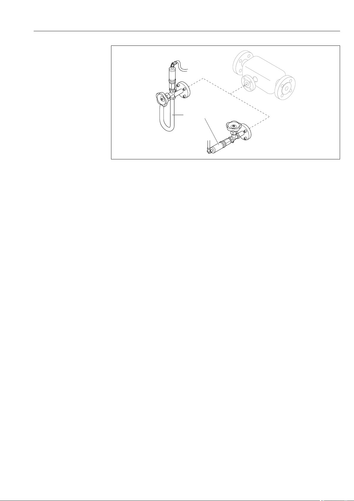
Pressure measuring cell
Steam pressure measurement Option DA
E • With the
transmitter
installed at the
bottom or at the
side
• Protection
against rising
heat
• Reduction in
temperature to
almost ambient
temperature due
to siphon
1)
A0034057
F
A0034058
Gas pressure measurement Option DB
G • Pressure
measuring cell
with shutoff
device above
tapping point
• Discharge of any
condensate into
the process
A0034092
Liquid pressure measurement Option DB
H Device with shutoff
device at the same
level as tapping
point
A0034091
1) Note max. permitted ambient temperature of transmitter→ 27.
Minimum spacing and cable length
Order code for "Sensor version", option "mass" DA, DB
The "mass" sensor version (integrated pressure/temperature measurement) is
available only for measuring devices in the HART communication mode.
A
L
A0019211
A Minimum spacing in all directions
L Required cable length

Installation Proline Prowirl F 200 HART
24 Endress+Hauser
The following dimensions must be observed to guarantee problem-free access to the device
for service purposes:
• A =100 mm (3.94 in)
• L = L + 150 mm (5.91 in)
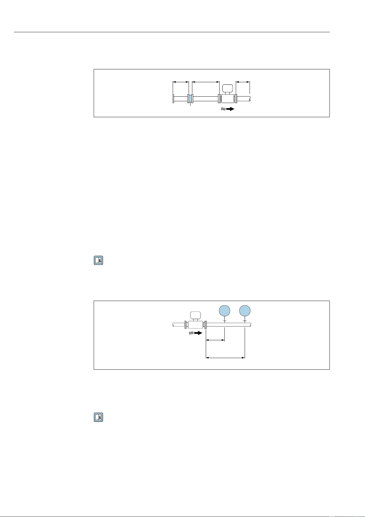
Inlet and outlet runs
To attain the specified level of accuracy of the measuring device, the inlet and outlet runs
mentioned below must be maintained at the very minimum.
Proline Prowirl F 200 HART Installation
Endress+Hauser 25
1
15 DN×
5 × DN
3
25 × DN
5 × DN
40 × DN
5 × DN
4
2
20 × DN
5 × DN
5
20 × DN
5 × DN
6
17 × DN + 8 × h
5 × DN
h
7
50 × DN
5 × DN
9
40 × DN
5 × DN
8
5 × DN
DN 25 (1"):≤
DN 40 (1½"):≥
A0019189
8 Minimum inlet and outlet runs with various flow obstructions
h Difference in expansion
1 Reduction by one nominal diameter size
2 Single elbow (90° elbow)
3 Double elbow (2 × 90° elbows, opposite)
4 Double elbow 3D (2 × 90° elbows, opposite, not on one plane)
5 T-piece
6 Expansion
7 Control valve
8 Two measuring devices in a row where DN ≤ 25 (1"): directly flange on flange
9 Two measuring devices in a row where DN ≥ 40 (1½"): for spacing, see graphic
• If there are several flow disturbances present, the longest specified inlet run must
be maintained.
• If the required inlet runs cannot be observed, it is possible to install a specially
designed flow conditioner → 25.
The inlet run correction function:
• Makes it possible to shorten the inlet run to a minimum length of 10 × DN in the
event of flow obstructions 1 to 4. An additional measuring uncertainty of ±0.5% o.r.
occurs here. → 111
• Cannot be combined with the wet steam detection/measurement application
package. If wet steam detection/measurement is used, the corresponding inlet runs
must be taken into consideration. It is not possible to use a flow conditioner for wet
steam.
Flow conditioner
If the inlet runs cannot be observed, the use of a flow conditioner is recommended.
Installation Proline Prowirl F 200 HART
26 Endress+Hauser
The flow conditioner is fitted between two pipe flanges and centered by the mounting
bolts. Generally this reduces the inlet run needed to 10 × DN with full accuracy.
8 DN×
2 DN×
5 DN×
1
A0019208
1 Flow conditioner
The pressure loss for flow conditioners is calculated as follows: ∆ p [mbar] = 0.0085 ⋅ ρ
[kg/m
3
] ⋅ v
2
[m/s]
Example for steam Example for H
2
O condensate (80 °C)
p = 10 bar abs. ρ = 965 kg/m
3
t = 240 °C → ρ = 4.39 kg/m
3
v = 2.5 m/s
v = 40 m/s ∆ p = 0.0085 ⋅ 965 ⋅ 2.5
2
= 51.3 mbar
∆ p = 0.0085 ⋅ 4.394.39 ⋅ 40
2
= 59.7 mbar
ρ : density of the process medium
v: average flow velocity
abs. = absolute
For the dimensions of the flow conditioner, see the "Technical Information" document,
"Mechanical construction" section
Outlet runs when installing external devices
If installing an external device, observe the specified distance.
3…5 × DN
4…8 × DN
PT
TT
A0019205
PT Pressure
TT Temperature device
Installation dimensions
For the dimensions and installation lengths of the device, see the "Technical
Information" document, "Mechanical construction" section.

Proline Prowirl F 200 HART Installation
Endress+Hauser 27
6.1.2 Environment and process requirements
Ambient temperature range
Compact version
Measuring device Non-hazardous area: –40 to +80 °C (–40 to +176 °F)
1)
Ex i, Ex nA, Ex ec: –40 to +70 °C (–40 to +158 °F)
1)
Ex d, XP: –40 to +60 °C (–40 to +140 °F)
1)
Ex d, Ex ia: –40 to +60 °C (–40 to +140 °F)
1)
Local display –40 to +70 °C (–40 to +158 °F)
2) 1)
1) Additionally available as order code for "Test, certificate", option JN "Transmitter ambient temperature –
50 °C (–58 °F)".
2) At temperatures < –20 °C (–4 °F), depending on the physical characteristics involved, it may no longer be
possible to read the liquid crystal display.
Remote version
Transmitter Non-hazardous area: –40 to +80 °C (–40 to +176 °F)
1)
Ex i, Ex nA, Ex ec: –40 to +80 °C (–40 to +176 °F)
1)
Ex d: –40 to +60 °C (–40 to +140 °F)
1)
Ex d, Ex ia: –40 to +60 °C (–40 to +140 °F)
1)
Sensor Non-hazardous area: –40 to +85 °C (–40 to +185 °F)
1)
Ex i, Ex nA, Ex ec: –40 to +85 °C (–40 to +185 °F)
1)
Ex d: –40 to +85 °C (–40 to +185 °F)
1)
Ex d, Ex ia: –40 to +85 °C (–40 to +185 °F)
1)
Local display –40 to +70 °C (–40 to +158 °F)
2) 1)
1) Additionally available as order code for "Test, certificate", option JN "Transmitter ambient temperature –
50 °C (–58 °F)".
2) At temperatures < –20 °C (–4 °F), depending on the physical characteristics involved, it may no longer be
possible to read the liquid crystal display.
‣
If operating outdoors:
Avoid direct sunlight, particularly in warm climatic regions.
You can order a weather protection cover from Endress+Hauser. → 168.
Thermal insulation
For optimum temperature measurement and mass calculation, heat transfer at the sensor
must be avoided for some fluids. This can be ensured by installing thermal insulation. A
wide range of materials can be used for the required insulation.
This applies for:
• Compact version
• Remote sensor version
The maximum insulation height permitted is illustrated in the diagram:
Installation Proline Prowirl F 200 HART
28 Endress+Hauser
1
A0019212
1 Maximum insulation height
‣
When insulating, ensure that a sufficiently large area of the housing support remains
exposed.
The uncovered part serves as a radiator and protects the electronics from overheating and
excessive cooling.
NOTICE
Electronics overheating on account of thermal insulation!
‣
Observe the maximum permitted insulation height of the transmitter neck so that the
transmitter head and/or the connection housing of the remote version is completely
free.
‣
Observe information on the permissible temperature ranges.
‣
Note that a certain orientation might be required, depending on the fluid temperature.
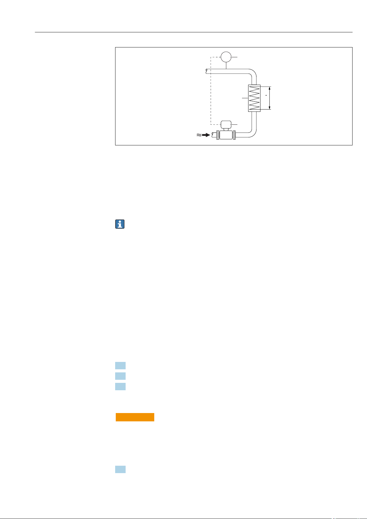
6.1.3 Special mounting instructions
Installation for delta heat measurements
• Order code for "Sensor version", option CA "mass; 316L; 316L (integrated temperature
measurement), –200 to +400 °C (–328 to +750 °F)"
• Order code for "Sensor version", option CB "mass; Alloy C22; 316L (integrated
temperature measurement), –200 to +400 °C (–328 to +750 °F)"
• Order code for "Sensor version", option CC "mass; Alloy C22; Alloy C22 (integrated
temperature measurement), –40 to +260 °C (–40 to +500 °F)"
• Order code for "Sensor version", option DA "mass steam; 316L; 316L (integrated
pressure/temperature measurement), –200 to +400 °C (–328 to +750 °F)"
• Order code for "Sensor version", option DB "mass gas/liquid; 316L; 316L (integrated
pressure/temperature measurement), –40 to +100 °C (–40 to +212 °F)"
The second temperature measurement is taken using a separate temperature sensor. The
measuring device reads in this value via a communication interface.
• In the case of saturated steam delta heat measurements, the measuring device must be
installed on the steam side.
• In the case of water delta heat measurements, the device can be installed on the cold or
warm side.
Proline Prowirl F 200 HART Installation
Endress+Hauser 29
Q
TT
1
2
3
A0019209
9 Layout for delta heat measurement of saturated steam and water
1 Measuring device
2 Temperature sensor
3 Heat exchanger
Q Heat flow
Protective cover
Observe the following minimum head clearance: 222 mm (8.74 in)
For information on the weather protection cover, see → 168
6.2 Mounting the measuring device
6.2.1 Required tools
For transmitter
• For turning the transmitter housing: Open-ended wrench8 mm
• For opening the securing clamps: Allen key3 mm
For sensor
For flanges and other process connections: Corresponding mounting tools
6.2.2 Preparing the measuring device
1. Remove all remaining transport packaging.
2. Remove any protective covers or protective caps present from the sensor.
3. Remove stick-on label on the electronics compartment cover.
6.2.3 Mounting the sensor
L
WARNING
Danger due to improper process sealing!
‣
Ensure that the inside diameters of the gaskets are greater than or equal to that of the
process connections and piping.
‣
Ensure that the gaskets are clean and undamaged.
‣
Install the gaskets correctly.
1. Ensure that the direction of the arrow on the sensor matches the flow direction of
the medium.
Installation Proline Prowirl F 200 HART
30 Endress+Hauser
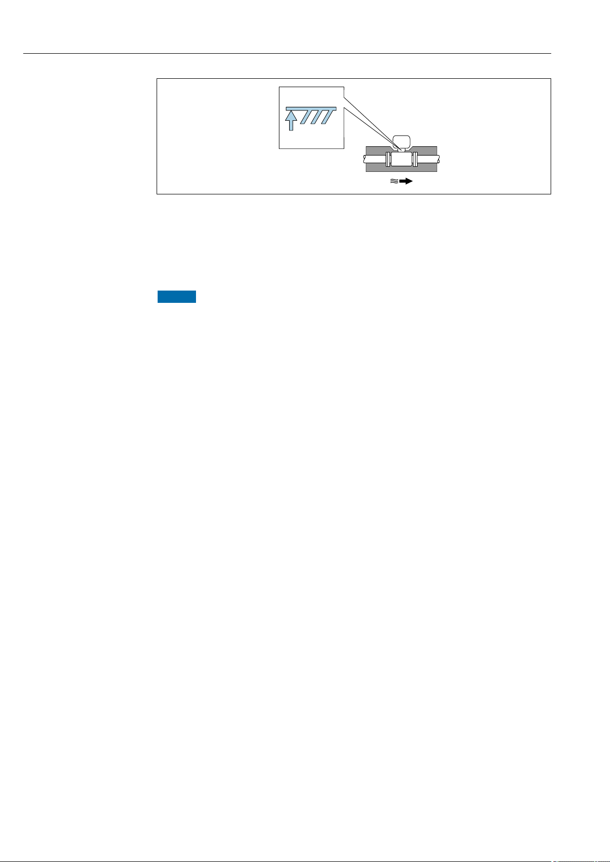
2. To ensure compliance with device specifications, install the measuring device
between the pipe flanges in a way that it is centered in the measurement section.
3. Install the measuring device or turn the transmitter housing so that the cable entries
do not point upwards.
A0029263
6.2.4 Mounting the pressure measuring unit
Preparation
1. Prior to mounting the pressure measuring unit, install the measuring device in the
pipe.
2. When mounting the pressure measuring unit, use only the seal provided. The use of a
different sealing material is not permitted.
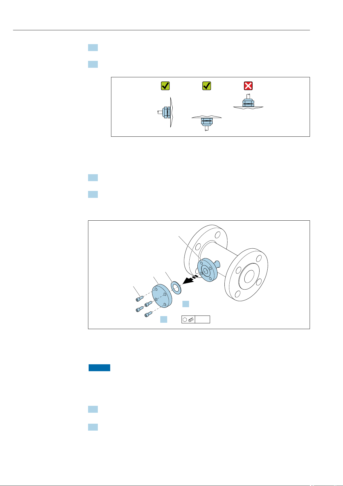
Removing the blind flange
1.
4
2.
1
3
2
4 x
6 mm
A0034355
1 Mounting screws
2 blind flange
3 Seal
4 Flange connection on sensor side
NOTICE
When replacing the seal following commissioning, fluid may escape when the flange
connection is opened!
‣
Ensure that the measuring device is not under pressure.
‣
Ensure that there is no fluid in the measuring device.
1. Release the mounting screws on the blind flange.
The screws are needed again to mount the pressure measuring unit.
2. Remove the internal seal.
Loading...