


 Loading...
BA00064S/04/EN/17.18 |
Products |
Solutions |
Services |
|
|
|
|
71393076 |
|
|
|
|
|
|
|
Valid from version |
|
|
|
SWG70-xx-1: 03.00.xx (firmware) |
|
|
|
SWG70-xx-2: 03.00.xx (firmware) |
|
|
|
SWG70-xx-3: 01.00.xx (firmware) |
|
|
|
Operating Instructions
WirelessHART Fieldgate SWG70
Intelligent WirelessHART gateway with Ethernet and RS-485 interface

WirelessHART Fieldgate SWG70 |
Table of Contents |
|
|
Table of Contents
Table of Contents . . . . . . . . . . . . . . . . . . . 3
Revision history . . . . . . . . . . . . . . . . . . . . 5
Registered Trademarks. . . . . . . . . . . . . . 5
1 Safety . . . . . . . . . . . . . . . . . . . . . . . . . . . . . 6
1.1 Designated use . . . . . . . . . . . . . . . . . . . . . . . . . . . . . 6 1.2 Installation, commissioning and operation . . . . . . 6 1.3 Operational safety . . . . . . . . . . . . . . . . . . . . . . . . . . . 6 1.4 IT security . . . . . . . . . . . . . . . . . . . . . . . . . . . . . . . . . . 7 1.5 Declaration of Conformity . . . . . . . . . . . . . . . . . . . . 7 1.6 Technical improvement . . . . . . . . . . . . . . . . . . . . . . 7 1.7 Conventions and icons . . . . . . . . . . . . . . . . . . . . . . . 8
2 Identification . . . . . . . . . . . . . . . . . . . . . . 9
2.1 Unpacking . . . . . . . . . . . . . . . . . . . . . . . . . . . . . . . . . 9 2.1.1 Visual inspection . . . . . . . . . . . . . . . . . . . . . 9 2.1.2 Scope of delivery . . . . . . . . . . . . . . . . . . . . . . 9 2.1.3 Storage and transport . . . . . . . . . . . . . . . . . 9
2.2 Nameplate . . . . . . . . . . . . . . . . . . . . . . . . . . . . . . . . . 9 2.3 Ordering information . . . . . . . . . . . . . . . . . . . . . . 10
3 Function and system design. . . . . . . . . 11
3.1 WirelessHART protocol . . . . . . . . . . . . . . . . . . . . 11 3.2 WirelessHART network . . . . . . . . . . . . . . . . . . . . 12 3.2.1 Network management . . . . . . . . . . . . . . . 12
3.2.2 WirelessHART security management . . 12
3.3Connecting to HART-compatible host systems . 13
|
3.3.1 |
Instrument list . . . . . . . . . . . . . . . . . . . . . |
13 |
|
3.3.2 |
Cache . . . . . . . . . . . . . . . . . . . . . . . . . . . . . |
14 |
4 |
Installation . . . . . . . . . . . . . . . . . . . . . . . |
15 |
|
4.1 |
Mounting considerations . . . . . . . . . . . . . . . . . . . |
15 |
|
|
4.1.1 |
Positioning the Fieldgate . . . . . . . . . . . . |
15 |
|
4.1.2 |
Antenna range . . . . . . . . . . . . . . . . . . . . . |
16 |
|
4.1.3 Examples of good and poor positioning |
17 |
|
4.2 |
Mounting the antenna . . . . . . . . . . . . . . . . . . . . . |
17 |
|
|
4.2.1 Mounting the antenna supplied . . . . . . . |
18 |
|
|
4.2.2 Connecting a remote antenna . . . . . . . . |
18 |
|
4.3 |
Mounting the Fieldgate . . . . . . . . . . . . . . . . . . . . |
19 |
|
5 |
Electrical Installation . . . . . . . . . . . . . . |
20 |
|
5.1 |
Connections and interfaces . . . . . . . . . . . . . . . . . |
20 |
|
5.2Connecting to power supply and grounding . . . 21
5.3 Connecting to Ethernet . . . . . . . . . . . . . . . . . . . . 22 5.3.1 Connecting the "Modbus" or "Modbus
+ OPC" versions to Ethernet . . . . . . . . . . 22 5.3.2 Connecting the "EtherNet/IP"
version to Ethernet . . . . . . . . . . . . . . . . . 23 5.4 Connecting to RS-485 . . . . . . . . . . . . . . . . . . . . . 24 5.5 Cable glands and housing cover . . . . . . . . . . . . . 25
Endress+Hauser
6 Operation . . . . . . . . . . . . . . . . . . . . . . . . 26
6.1 Operating and display elements . . . . . . . . . . . . . . 26 6.1.1 LEDs . . . . . . . . . . . . . . . . . . . . . . . . . . . . . . . 27 6.1.2 Buttons . . . . . . . . . . . . . . . . . . . . . . . . . . . . 28 6.1.3 DIP switches . . . . . . . . . . . . . . . . . . . . . . . . 29
7 Commissioning . . . . . . . . . . . . . . . . . . . 31
7.1 Ethernet connection . . . . . . . . . . . . . . . . . . . . . . . . 31
7.1.1Establishing the connection between the host computer
and the Fieldgate SWG70 Web server . . 33 7.2 RS-485 connection . . . . . . . . . . . . . . . . . . . . . . . . . 34 7.3 Creating a FieldCare project . . . . . . . . . . . . . . . . . 34 7.3.1 Adding the HART IP CommDTM . . . . . . . 34 7.3.2 Adding the Fieldgate SWG70 . . . . . . . . . . 36 7.3.3 Parameterizing Fieldgate SWG70 . . . . . . 37
7.3.4 Scanning for wireless devices
in the network . . . . . . . . . . . . . . . . . . . . . . 38 7.3.5 Scanning for devices connected
to adapters . . . . . . . . . . . . . . . . . . . . . . . . . 39 7.4 User interface . . . . . . . . . . . . . . . . . . . . . . . . . . . . . 40
8 |
Fieldgate configuration . . . . . . . . . . . . |
42 |
|
8.1 |
Identification . . . . . . . . . . . . . . . . . . . . . . . . . . . . . . |
42 |
|
8.2 |
Wireless Communication . . . . . . . . . . . . . . . . . . . . |
43 |
|
|
8.2.1 |
Basic Setup . . . . . . . . . . . . . . . . . . . . . . . . . |
43 |
|
8.2.2 |
Advanced Setup . . . . . . . . . . . . . . . . . . . . . |
45 |
|
8.2.3 |
Operating Modes . . . . . . . . . . . . . . . . . . . . |
47 |
8.3 |
Interfaces (wired communication) . . . . . . . . . . . . |
48 |
|
|
8.3.1 |
Ethernet . . . . . . . . . . . . . . . . . . . . . . . . . . . |
48 |
|
8.3.2 |
Serial (RS-485) . . . . . . . . . . . . . . . . . . . . . . |
49 |
8.4 |
Protocols (wired communication) . . . . . . . . . . . . |
50 |
|
|
8.4.1 Modbus via Ethernet or RS-485 . . . . . . . |
50 |
|
|
8.4.2 |
EtherNet/IP via Ethernet . . . . . . . . . . . . . |
51 |
|
8.4.3 HART via Ethernet or RS-485 . . . . . . . . . |
51 |
|
|
8.4.4 |
AMS via Ethernet . . . . . . . . . . . . . . . . . . . . |
52 |
9 Diagnostics . . . . . . . . . . . . . . . . . . . . . . . 53
9.1 Identification . . . . . . . . . . . . . . . . . . . . . . . . . . . . . . 53
9.2 Wireless Communication . . . . . . . . . . . . . . . . . . . . 54
9.2.1 Overview . . . . . . . . . . . . . . . . . . . . . . . . . . . 54
9.2.2 Details . . . . . . . . . . . . . . . . . . . . . . . . . . . . . 55
9.2.3 Burst Lists . . . . . . . . . . . . . . . . . . . . . . . . . . 56
9.2.4 Topology View (Diagnostics) . . . . . . . . . . 57
9.3 Wired Communication . . . . . . . . . . . . . . . . . . . . . . 58
9.3.1 Overview . . . . . . . . . . . . . . . . . . . . . . . . . . . 58
9.3.2 HART . . . . . . . . . . . . . . . . . . . . . . . . . . . . . . 60
10 Engineering . . . . . . . . . . . . . . . . . . . . . . 62
10.1 Instrument List . . . . . . . . . . . . . . . . . . . . . . . . . . . . 62 10.1.1 General . . . . . . . . . . . . . . . . . . . . . . . . . . . . 62 10.1.2 Creating and editing an Instrument List . 63 10.2 Topology View (Engineering) . . . . . . . . . . . . . . . . 65
3

WirelessHART Fieldgate SWG70 |
Table of Contents |
|
|
10.3 |
Configuring Modbus . . . . . . . . . . . . . . . . . . . . . . . |
68 |
|
10.3.1 Modbus Settings . . . . . . . . . . . . . . . . . . . . |
68 |
|
10.3.2 Input Status . . . . . . . . . . . . . . . . . . . . . . . . |
69 |
|
10.3.3 Input Register . . . . . . . . . . . . . . . . . . . . . . |
73 |
10.4 Configuring a WirelessHART OPC server . . . . . . |
76 |
|
|
10.4.1 System architecture of an |
|
|
OPC WirelessHART network . . . . . . . . . . |
77 |
|
10.4.2 Configuring the WirelessHART |
|
|
OPC server with "WirelessHART |
|
|
Fieldgate OPC Configurator" . . . . . . . . . . |
78 |
|
10.4.3 Description of the WirelessHART |
|
|
Fieldgate OPC Configurator . . . . . . . . . . |
81 |
|
10.4.4 Configuring bursts using |
|
|
the WirelessHART OPC server . . . . . . . . |
84 |
10.5 |
EtherNet/IP configuration . . . . . . . . . . . . . . . . . . |
88 |
|
10.5.1 Setting up an EtherNet/IP connection . . |
88 |
|
10.5.2 Assigning data exchange connections |
|
|
via HART descriptors . . . . . . . . . . . . . . . . |
88 |
|
10.5.3 Burst commands |
|
|
for cyclic data exchange . . . . . . . . . . . . . |
89 |
|
10.5.4 Integrating SWG70 into a PLC |
|
|
via EtherNet/IP . . . . . . . . . . . . . . . . . . . . . |
90 |
|
10.5.5 Cyclic data exchange |
|
|
via the ControlLogix® controller system |
90 |
|
10.5.6 Connection parameters |
|
|
for cyclic data exchange . . . . . . . . . . . . . |
95 |
10.5.7 Diagnostic bits in cyclic data exchange . 98
10.6Downstream Communication
|
(for discreet field devices) . . . . . . . . . . . . . . . . . |
. 99 |
10.7 |
Substitution value (substitution value to DCS) |
100 |
|
10.7.1 Burst message monitoring . . . . . . . . . . |
101 |
|
10.7.2 Factory Acceptance Test (FAT) . . . . . . |
103 |
10.8 |
Security – Whitelist, Temporary Join Key . . . . |
103 |
11 |
Additional Functions . . . . . . . . . . . . . |
106 |
11.1 |
Reset . . . . . . . . . . . . . . . . . . . . . . . . . . . . . . . . . . . |
106 |
11.2 |
Self Test . . . . . . . . . . . . . . . . . . . . . . . . . . . . . . . . |
107 |
11.3 |
Firmware Upgrade (Web Server) . . . . . . . . . . . |
107 |
11.4 |
Change Password (Web Server) . . . . . . . . . . . . |
108 |
11.5 |
Set DTM Addresses (DTM) . . . . . . . . . . . . . . . . |
108 |
11.6 |
Set Device Addresses (DTM) . . . . . . . . . . . . . . . |
109 |
11.7 |
Upload Certificate (Web server) . . . . . . . . . . . . |
110 |
|
11.7.1 Self-signed security certificate . . . . . . . |
110 |
|
11.7.2 Trusted security certificate . . . . . . . . . . |
110 |
11.8 |
Auto Refresh . . . . . . . . . . . . . . . . . . . . . . . . . . . . |
111 |
12 |
Measurement. . . . . . . . . . . . . . . . . . . . |
112 |
13 |
Maintenance and repair. . . . . . . . . . . |
113 |
13.1 |
Maintenance . . . . . . . . . . . . . . . . . . . . . . . . . . . . |
113 |
13.2 |
Return to Endress+Hauser. . . . . . . . . . . . . . . . . |
113 |
13.3 |
Disposal . . . . . . . . . . . . . . . . . . . . . . . . . . . . . . . . |
113 |
13.4 |
Contact addresses . . . . . . . . . . . . . . . . . . . . . . . . |
113 |
13.5 |
Accessories and spare parts . . . . . . . . . . . . . . . . |
113 |
14 Troubleshooting . . . . . . . . . . . . . . . . . 114
14.1 Faults indicated by Fieldgate LEDs . . . . . . . . . . 114 14.2 Wired Communication Faults . . . . . . . . . . . . . . 114 14.3 Wireless Communication Faults . . . . . . . . . . . . 115
14.4Error messages of the WirelessHART
OPC server in the "Event Viewer" window . . . . 116
15 Technical data. . . . . . . . . . . . . . . . . . . 117
16 Modbus Interface . . . . . . . . . . . . . . . . 118
16.1 Introduction . . . . . . . . . . . . . . . . . . . . . . . . . . . . . 118 16.1.1 Modbus protocol . . . . . . . . . . . . . . . . . . 118 16.1.2 Modbus in Fieldgate . . . . . . . . . . . . . . . 119 16.1.3 Data types . . . . . . . . . . . . . . . . . . . . . . . . 122 16.2 Rules for mapping . . . . . . . . . . . . . . . . . . . . . . . 123
16.2.1 Automatic mapping of analog devices (HART CMD 3) . . . . . . . . . . . . . . . . . . . . 123
16.2.2 Digital input/output devices . . . . . . . . . 124 16.3 Mapping formats . . . . . . . . . . . . . . . . . . . . . . . . 125 16.3.1 Dynamic process variables . . . . . . . . . . 125 16.3.2 Status mapping . . . . . . . . . . . . . . . . . . . 125
16.3.3HART CMD48
Read Additional Status Information . . 126
16.3.4 Read Digital Inputs . . . . . . . . . . . . . . . . 127
17 CSV file formats . . . . . . . . . . . . . . . . . 128
17.1 Structure of the CSV files . . . . . . . . . . . . . . . . . . 128 17.2 Modbus Mapping CSV files . . . . . . . . . . . . . . . . 128 17.3 Instrument List CSV files . . . . . . . . . . . . . . . . . . 129 17.4 Topology View CSV file . . . . . . . . . . . . . . . . . . . 129 17.5 Details . . . . . . . . . . . . . . . . . . . . . . . . . . . . . . . . . 130
18 Table Device Variable Classification
and Unit Code . . . . . . . . . . . . . . . . . . . 131
Index. . . . . . . . . . . . . . . . . . . . . . . . . . . 139
4 |
Endress+Hauser |
WirelessHART Fieldgate SWG70 |
Revision history |
|
|
Revision history
Order code |
Product version |
Manual |
Changes |
Remarks |
SWG70-xx-1 |
1.00.xx |
BA064S/04/en/06.10 |
– |
First version of Operating Instructions |
SWG70-xx-1 |
1.01.xx |
BA00064S/04/en/13.13 |
New Functions |
• Navigation changed, Chapter 7.6 |
|
|
|
|
• Channel Blacklisting possible, |
|
|
|
|
Chapter 8.2.2 |
|
|
|
|
• Topology with signal strength, |
|
|
|
|
Chapter 9.2.4 and 10.3 |
|
|
|
|
• Network tables revised, e.g. |
|
|
|
|
Chapter 8.2.3 |
|
|
|
|
|
|
|
|
Manual Restructuring |
• Chapter 8 Fieldgate configuration => |
|
|
|
|
Chapters 8 to 12 |
|
|
|
|
• Chapter 10 Modbus => Appendix A |
|
|
|
|
• Chapter 9 HART OPC Server => |
|
|
|
|
Appendix B |
|
|
|
|
|
SWG70-xx-1 |
2.00.xx |
BA00064S/04/en/14.14 |
Description of the WirelessHART |
• New Chapter 1.4 "IT security" |
|
|
|
Fieldgate OPC Configurator and burst |
• New Chapter 11 "WirelessHART |
SWG70-xx-2 |
2.00.xx |
|
||
|
|
|
configuration |
Fieldgate OPC Configurator" |
|
|
|
|
• Deleted Appendix C "HART OPC |
|
|
|
|
Connection" |
|
|
|
|
|
SWG70-xx-1 |
2.03.xx |
BA00064S/04/en/15.15 |
New Functions |
• EtherNet/IP amended |
|
|
|
Manual Restructuring |
• Technical data moved to Technical |
SWG70-xx-2 |
2.03.xx |
|
||
|
|
Information for "WirelessHART- |
||
|
|
|
|
|
SWG70-xx-3 |
1.01.xx |
|
|
Fieldgate SWG70" (TI00027S) |
|
|
|
|
|
SWG70-xx-3 |
1.00.xx |
BA00064S/04/en/16.16 |
Correction of product version with order |
• Editorial changes, removal of all |
|
|
|
code SWG70-xx-3 from 1.01.xx to 1.00.xx |
references to "CD-Rom" |
|
|
|
|
|
SWG70-xx-1 |
3.00.xx |
BA00064S/04/en/17.18 |
New functions |
• Notice in Chapter 1.1 added |
|
|
|
The new functions are not included in |
• Chapter 7.1.1 edited |
SWG70-xx-2 |
3.00.xx |
|
||
|
version SWG70-xx-3. |
• Chapter 8.2.1 edited |
||
|
|
|
||
|
|
|
|
• New chapters 10.6, 10.7, 10.8 |
|
|
|
|
• Chapter 11.4 edited |
|
|
|
|
• New Chapter 11.9 |
|
|
|
|
|
Registered Trademarks
HART® and WirelessHART®
Registered trademarks of the HART Communication Foundation, Austin/Texas, USA
Microsoft® and Windows®
Registered trademarks of the Microsoft Corporation.
PC Easy Connect Suite®
Registered trademark of Softing AG
ControlLogix®
Registered trademark of Rockwell Automation
MatrikonOPC TunnellerTM Registered trademark of MatrikonOPC
All other brand and product names are trademarks or registered trademarks of the companies and organizations in question.
Endress+Hauser |
5 |

Safety |
WirelessHART Fieldgate SWG70 |
|
|
1 Safety
1.1Designated use
Fieldgate SWG70 serves as a gateway for WirelessHART networks. It enables WirelessHART devices to communicate with each other and manages security and connectivity. The Fieldgate converts wireless device data to a format that is compatible with host systems.
NOTICE!
•The WirelessHART protocol may not be used to replace the wiring in the case of safety applications with a control function.
1.2Installation, commissioning and operation
The WirelessHART Fieldgate can be operated safely in compliance with the current guidelines for technical safety and the latest EU directives. Wireless field devices and adapters connected to the WirelessHART Fieldgate must also be operated in accordance with the current guidelines for technical safety and the latest EU directives.
If the WirelessHART Fieldgate is installed incorrectly or used in applications for which it is not intended, it is possible that dangers may arise.
Installation, connection to the electricity supply, commissioning, operation and maintenance of the WirelessHART Fieldgate may only be carried out by trained, qualified technical specialists authorized to perform such work by the facility's owner-operator. The specialist staff must have read and understood these Operating Instructions and must follow the instructions they contain. It is not permitted to modify or repair the devices in any way.
NOTICE!
•Changes or modifications to the Fieldgate not expressly approved by Endress+Hauser will void the user’s authority to operate the equipment.
|
1.3 |
Operational safety |
Location |
Fieldgate SWG70 fulfills the requirements of EU Guidelines for a number of applications. |
|
|
The associated environmental conditions must be upheld. See the Technical Information |
|
|
document for "WirelessHART Fieldgate SWG70" (TI00027S). |
|
|
The device must not be installed at locations where corrosive vapors may be present. |
|
Hazardous areas |
Fieldgate SWG70 is available in a version that can be mounted in an explosion hazardous |
|
|
area. In order to ensure the necessary degree of protection: |
|
• All seals must be undamaged and have been correctly fitted.
• All screws of the housing/housing cover must have been tightened with the appropriate torque.
• Only cable of the appropriate size must be used in the cable glands.
• All cable glands must have been tightened with the appropriate torque, see (Chapter 5.5).
• All empty cable glands must have been sealed with sealing plugs.
6 |
Endress+Hauser |

WirelessHART Fieldgate SWG70 |
Safety |
|||
|
|
|
|
|
|
|
|
When installing components in explosion hazardous areas: |
|
|
|
|
• Ensure that all installation and maintenance personnel are suitably qualified. |
|
|
|
|
• Check that all equipment has the appropriate safety certificates. |
|
|
|
|
• Observe the specifications in the device certificates as well as national and local |
|
|
|
|
regulations. |
|
Coexistence of wireless |
WirelessHART networks use the frequency spectrum between 2400 ... 2483.5 MHz accord- |
|||
technologies |
ing to IEEE 802.15.4. Various other wireless technologies also use this frequency spectrum, |
|||
|
|
|
for example WLAN and Bluetooth. Depending upon the situation, it is possible that these |
|
|
|
|
different wireless technologies will affect each other. |
|
|
|
|
When wireless technologies are used in an industrial environment, they must coexist with- |
|
|
|
|
out interfering with each other. If you find that systems are interfering with each other, take |
|
|
|
|
appropriate measures to ensure the operation of all wireless systems, e.g. by reconfiguring, |
|
|
|
|
enforcing a wireless compatibility policy, etc. |
|
Operation |
CAUTION! |
|
||
|
|
|
Maintain a minimum distance of 20 cm between the device antenna and the body of the user |
|
|
|
|
||
|
|
|
||
|
|
|
and all persons in the vicinity at all times and for all applications and uses. |
|
|
|
|
1.4 |
IT security |
|
|
|
The Fieldgate SWG70 is equipped with security mechanisms to protect it against any |
|
|
|
|
inadvertent changes to the device settings. Additional IT security measures in line with |
|
|
|
|
operators' security standards and designed to provide additional protection for the device |
|
|
|
|
and device data transfer must be implemented by the operators themselves. |
|
|
|
|
The Fieldgate offers the following functions that increase IT security: |
|
|
|
|
• WirelessHART security management (See Chapter 3.2.2 "WirelessHART security |
|
|
|
|
management" on page 12 and see Chapter 8.2.1 "Basic Setup" on page 43.) |
|
|
|
|
• Password for Web server (See Chapter 11.4 "Change Password (Web Server)" on |
|
|
|
|
page 108.) |
|
|
|
|
• Security certificate for Web server (See Chapter 11.7 "Upload Certificate (Web server)" on |
|
|
|
|
page 110.) |
|
|
|
|
See the Technical Information document "WirelessHART Fieldgate SWG70" (TI00027S) for |
|
|
|
|
system-specific firewall configurations such as TCP/IP ports and services. |
|
|
|
|
1.5 |
Declaration of Conformity |
|
|
|
All Declarations of Conformity can be found on www.endress.com. |
|
CE Mark |
The WirelessHART Fieldgate SWG70 meets the legal requirements of the relevant EC direc- |
|||
|
|
|
tives. Endress+Hauser confirms successful testing of the WirelessHART Fieldgate SWG70 by |
|
|
|
|
affixing to it the CE mark. An EC Declaration of Conformity has been issued for the Ex-ver- |
|
|
|
|
sions and non-Ex versions of the device. |
|
|
|
|
1.6 |
Technical improvement |
|
|
|
Endress+Hauser reserves the right to make technical improvements to its software and |
|
|
|
|
equipment at any time and without prior notification. Where such improvements have no |
|
effect on the operation of the equipment, they are not documented. If the improvements effect operation, a new version of the operating instructions is normally issued.
Endress+Hauser |
7 |
Safety |
WirelessHART Fieldgate SWG70 |
|
|
1.7Conventions and icons
In order to highlight safety relevant or alternative operating procedures in the manual, the following conventions have been used, each indicated by a corresponding icon in the margin.
Safety conventions |
|
|
|
|
|
|
|
|
|
|
|
|
|
|
|
|
|
Icon |
|
|
|
|
|
|
|
Meaning |
|
||||
|
|
|
|
|
|
|
|
|
|
|
|
|
|
DANGER! |
|
|
|
|
|
|
|
|
|
|
|
|
|
|
|
This symbol alerts you to a dangerous situation. Failure to avoid this situation will result |
|
|
|
|
|
|
|
|
|
|
|
|
|
|
|
in serious or fatal injury. |
|
|
|
|
|
|
|
|
|
|
|
|
|
|
|
|
|
|
|
|
|
|
|
|
|
|
|
|
|
|
|
WARNING! |
|
|
|
|
|
|
|
|
|
|
|
|
|
|
|
This symbol alerts you to a dangerous situation. Failure to avoid this situation can result |
|
|
|
|
|
|
|
|
|
|
|
|
|
|
|
in serious or fatal injury. |
|
|
|
|
|
|
|
|
|
|
|
|
|
|
|
|
|
|
|
|
|
|
|
|
|
|
|
|
|
|
|
CAUTION! |
|
|
|
|
|
|
|
|
|
|
|
|
|
|
|
This symbol alerts you to a dangerous situation. Failure to avoid this situation can result |
|
|
|
|
|
|
|
|
|
|
|
|
|
|
|
in minor or medium injury. |
|
|
|
|
|
|
|
|
|
|
|
|
|
|
|
|
|
|
|
|
|
|
|
|
|
|
|
|
|
|
|
NOTICE! |
|
|
|
|
|
|
|
|
|
|
|
|
|
|
|
This symbol contains information on procedures and other facts which do not result in |
|
Type of protection |
|
|
|
|
|
|
|
|
|
|
|
|
|
personal injury. |
|
|
|
|
|
|
|
|
|
|
|
|
|
|
|
|
|
|
.Icon |
|
|
|
Meaning |
|
|||||||||
|
|
|
|
|
|||||||||||
|
|
|
|
|
|
|
|
|
|
|
|
||||
|
|
|
|
|
|
|
|
|
|
Device certified for use in explosion hazardous area |
|
||||
|
|
|
|
|
|
|
|
|
|
If the device has this symbol embossed on its name plate it can be installed in an explosion |
|
||||
|
|
|
|
|
|
|
|
|
|
hazardous area in accordance with the specifications in the certificate or in a safe area. |
|
||||
|
|
|
|
|
|
|
|
|
|
|
|
||||
|
|
|
|
|
|
|
|
|
|
Explosion hazardous area |
|
||||
|
|
|
|
|
|
|
|
|
|
Symbol used in drawings to indicate explosion hazardous areas. Devices located in and wiring |
|
||||
|
|
|
|
|
|
|
|
|
|
entering areas with the designation “explosion hazardous areas” must conform with the stated type |
|
||||
|
|
|
|
|
|
|
|
|
|
of protection. |
|
||||
|
|
|
|
|
|
|
|
|
|
|
|||||
|
|
|
|
|
|
|
|
|
|
|
|
||||
|
|
|
|
|
|
|
|
|
|
Safe area (non-explosion hazardous area) |
|
||||
|
|
|
|
|
|
|
|
|
|
Symbol used in drawings to indicate, if necessary, non-explosion hazardous areas. Devices located |
|
||||
|
|
|
|
|
|
|
|
|
|
in safe areas still require a certificate if their outputs run into explosion hazardous areas. |
|
||||
Electrical symbols |
|
|
|
|
|
|
|
|
|
|
|
|
|
|
|
|
.Icon |
|
|
|
Meaning |
|
|||||||||
|
|
|
|
|
|||||||||||
|
|
|
|
|
|
|
|
|
|
|
|
||||
|
|
|
|
|
|
|
|
|
|
Direct voltage |
|
||||
|
|
|
|
|
|
|
|
|
|
A terminal to which or from which a direct current or voltage may be applied or supplied. |
|
||||
|
|
|
|
|
|
|
|
|
|
|
|
|
|
|
|
|
|
|
|
|
|
|
|
|
|
|
|
|
|
|
|
|
|
|
|
|
|
|
|
|
|
Alternating voltage |
|
||||
|
|
|
|
|
|
|
|
|
|
A terminal to which or from which an alternating (sine-wave) current or voltage may be applied or |
|
||||
|
|
|
|
|
|
|
|
|
|
supplied. |
|
||||
|
|
|
|
|
|
|
|
|
|
|
|
||||
|
|
|
|
|
|
|
|
|
|
Grounded terminal |
|
||||
|
|
|
|
|
|
|
|
|
|
|
|||||
|
|
|
|
|
|
|
|
|
|
A grounded terminal, which as far as the operator is concerned, is already grounded by means of an |
|
||||
|
|
|
|
|
|
|
|
|
|
earth grounding system. |
|
||||
|
|
|
|
|
|
|
|
|
|
|
|||||
|
|
|
|
|
|
|
|
|
|
|
|
||||
|
|
|
|
|
|
|
|
|
|
|
|
|
|
|
|
|
|
|
|
|
|
|
|
|
|
|
|
|
|
|
|
|
|
|
|
|
|
|
|
|
|
Protective grounding (earth) terminal |
|
||||
|
|
|
|
|
|
|
|
|
|
|
|||||
|
|
|
|
|
|
|
|
|
|
|
|||||
|
|
|
|
|
|
|
|
|
|
A terminal which must be connected to earth ground prior to making any other connection to the |
|
||||
|
|
|
|
|
|
|
|
|
|
|
|||||
|
|
|
|
|
|
|
|
|
|
equipment. |
|
||||
|
|
|
|
|
|
|
|
|
|
|
|||||
|
|
|
|
|
|
|
|
|
|
|
|||||
|
|
|
|
|
|
|
|
|
|
|
|
||||
|
|
|
|
|
|
|
|
|
|
|
|
|
|
|
|
|
|
|
|
|
|
|
|
|
|
Equipotential connection (earth bonding) |
|
||||
|
|
|
|
|
|
|
|
|
|
|
|||||
|
|
|
|
|
|
|
|
|
|
|
|||||
|
|
|
|
|
|
|
|
|
|
A connection made to the plant grounding system which may be of type e.g. neutral star or |
|
||||
|
|
|
|
|
|
|
|
|
|
|
|||||
|
|
|
|
|
|
|
|
|
|
equipotential line according to national or company practice. |
|
||||
|
|
|
|
|
|
|
|
|
|
|
|
|
|
|
|
|
|
|
|
|
|
|
|
|
|
|
|
|
|
|
|
8 |
Endress+Hauser |
WirelessHART Fieldgate SWG70 |
Identification |
|
|
2 Identification
2.1Unpacking
2.1.1Visual inspection
During unpacking:
•Check the packing materials for signs of transportation damage.
•Remove the packaging material with care, so as not to damage the Fieldgate.
•Store the original packing material, in case the Fieldgate must be shipped again.
•Keep the documentation supplied with the Fieldgate in a safe place.
•Keep the accompanying documents.
2.1.2Scope of delivery
Please check that the delivery is complete and free of defects before starting installation.
The scope of delivery comprises the following parts:
•WirelessHART Fieldgate SWG70
•Antenna
•Short instructions
•Depending upon order, FieldCare Device Setup DVD
2.1.3Storage and transport
Always store and transport the device in the original packaging. Always store the device in a clean, dry environment.
Keep within the permitted storage temperature range. See the Technical Information document for "WirelessHART Fieldgate SWG70" (TI00027S).
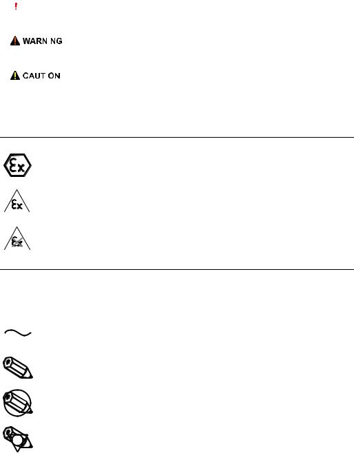
2.2Nameplate
The device designation together with other information can be found on the nameplate affixed to the front of the Fieldgate.
1
Made in Germany CH-4153 Reinach, Switzerland |
|
|
|
|
|
|
|||
WirelessHART Fieldgate SWG70 |
|
|
|
|
|||||
Order code: |
SWG70-1056/0 |
U: |
DC 20...30 V |
Contains: |
2.4 GHz |
|
x |
НАНИО “ЦСВЭ” |
IP 66 / IP 67 / NEMA 4 |
Ser. no.: |
60011009001 |
P: |
< 5 W |
FCC-ID: |
SJC-M2140 |
|
No.: TC RU C-CH.ГБ05.В.00043 |
|
|
Ext. ord. cd.: |
SWG70-BG3 |
Ta: |
-20 °C...+60 °C |
IC-ID: |
5853A-M2140 |
|
2ExnAIIT4 X |
|
|
|
|
HW: |
01.00.00 |
CMIIT-ID: 2011DJ5310 |
|
|
MAC: DD-DD-BE-DD-DD-BB |
||
|
|
Dev.Rev.: 1 |
Anatel ID: HHHHFF-AAAA |
|
XA00C01S |
||||
|
|
FW: |
01.00.01 |
|
R 202-SMD11 |
|
|
Dat./Insp.: 2015-07-06 |
|
0976 |
FW: |
|
|
|
|
II 3 G Ex nA nC IIC T4 Gc |
|||
|
|
|
|
|
|
||||
|
|
|
4 |
|
3 |
|
|
2 |
|
|
|
|
|
Fig. 2-1: Nameplate (example) |
|
||||
1 Order number and serial number |
|
|
3 |
Telecommunication compliance |
|||||
2 Type of protection, if any |
|
|
|
4 |
Version information |
|
|||
Endress+Hauser |
9 |
Identification |
WirelessHART Fieldgate SWG70 |
|
|
2.3Ordering information
Detailed information about the product structure is available:
•On the Endress+Hauser website: www.endress.com/SWG70
•From your Endress+Hauser Sales Center: www.addresses.endress.com
10 |
Endress+Hauser |

WirelessHART Fieldgate SWG70 |
Function and system design |
|
|
3 Function and system design
3.1WirelessHART protocol
The HART protocol has until now used the wired 4–20 mA loop with a superimposed digital signal as physical layer.
WirelessHART enables the wireless transmission of HART data. To be employable worldwide, WirelessHART utilizes the 2.4 GHz Band (IEEE 802.15.4 wireless network) as physical layer. The WirelessHART devices form a mesh network in which every device is not just a measurement point, but also a repeater. This results in a wider range for the whole network as well as increased reliability through redundant communication paths.
The network may comprise three types of device:
•WirelessHART gateway (Fieldgate SWG70)
•WirelessHART field devices
•WirelessHART Adapters (SWA70): either connected to 4–20 mA/HART devices or acting as repeaters.
The WirelessHART network is built up, organized and maintained by the Fieldgate, which also takes care for connection to different HOST systems through different bus interfaces.
1
Ethernet 2
4 |
3 |
|
4
4 |
4
 4 4
4 4 

|
|
|
|
|
|
|
|
|
|
|
|
|
|
|
|
|
|
|
|
|
|
Fig. 3-1: WirelessHART network |
|||||||
1 |
Host applications |
3 |
WirelessHART Fieldgate |
||||||
2 |
Ethernet |
4 |
Field devices with wireless |
||||||
Endress+Hauser |
11 |

Function and system design |
WirelessHART Fieldgate SWG70 |
|
|
3.2WirelessHART network
Fieldgate SWG70 is the master device in the WirelessHART network. Acting as network manager, it recognizes other devices wanting to join the network. It makes contact with each in turn and initiates the procedures required for them to join. The network organizes itself without any intervention on the part of the user. Fieldgate SWG70 also acts as security manager and collects the data sent by the network participants, converting it into a form which can be used by other systems connected to it.
3.2.1Network management
In its role as network manager, Fieldgate SWG70 organizes the wireless communication between the WirelessHART field devices.
|
4 |
|
|
|
|
|
|
|
|
|
|
|
1 |
|
5 |
|
|
|
|
|
|
|
|
|
|
|
|
|
|
|
|
|
|||
|
|
|
|
|
|
|
|
|
|
|
|
|
|
2 |
|
|
|
|
|
|
|
|
|
|
|
|
|
|
|
|
|
|
|
||
|
|
|
|
|
|
|
|
|
|
|
|
|
|
3 |
|
|
|
|
|
|
|
|
|
|
|
|
|
|
|
|
|
|
|
|
|
|
|
|
|
|
|
|
|
|
|
|
|
|
|
|
|
|
|
|
|
|
|
|
|
|
|
|
|
|
|
|
|
|
|
||
|
|
|
|
|
|
|
|
|
|
|
|
|
|
|
|
||
|
|
|
|
|
|
|
|
|
|
|
|
|
|
|
|
|
|
|
|
|
|
|
|
|
|
|
|
|
|
|
Fig. 3-2: Network management |
|
|
||
|
|
|
|
|
|
|
|
|
|
|
|
|
|
|
|||
1 |
Step 1: Advertising |
4 |
WirelessHART gateway (Fieldgate SWG70) |
||||||||||||||
2 |
Step 2: Join Request |
5 |
WirelessHART device or adapter |
|
|
||||||||||||
3Step 3: Authorization, Session & Network Keys, Scheduling and Routing
After the Fieldgate has started up the network, devices can join. To this end, it first sends out a call for devices to join the network. Then, the device sends a join request to announce its wish to join the network. If the WirelessHART field device can identify itself with the same network ID and join key as stored in the WirelessHART Fieldgate, the field device is authorized to join the network. Otherwise, the field device will be rejected.
In the next step, the WirelessHART Fieldgate sends session and network keys as well as scheduling and routing information to the field device. The field device is told how to participate in the network and receives various information from the WirelessHART Fieldgate:
•Number and identity of neighboring WirelessHART field devices,
•When to send messages and which channels to use,
•When to repeat messages for other WirelessHART field devices,
•The optimal communication path for messages as well as alternative communication paths in case of failure.
During this process, the WirelessHART device or adapter may also apply to send messages in certain intervals and ask the network manager for the appropriate resources. The network manager then takes care that these resources are available. For example, the network manager informs other WirelessHART field devices when to repeat messages.
3.2.2WirelessHART security management
Fieldgate SWG70 also acts as security manager. To make communication safe, all messages are encrypted with industry-standard AES-128 block ciphers with symmetric keys. Therefore, messages are unreadable for external listeners. The encryption keys are distributed by the security manager.
The Join Key is used to join the network. Subsequently, the Join Key is automatically exchanged against the Session Key and the Network Key, i.e. two new additional keys.
12 |
Endress+Hauser |

WirelessHART Fieldgate SWG70 |
Function and system design |
|
|
3.3Connecting to HART-compatible host systems
Fieldgate SWG70 also makes wireless communication accessible to HART-capable host systems via its Ethernet interface or serial interfaces (RS-485) and the following functions.
Depending on the version ordered, Fieldgate SWG70 can also be integrated into Modbus, OPC or Ethernet/IP host systems.
3.3.1Instrument list
The WirelessHART devices in the network are made available to the host systems via an instrument list. This list contains one or more I/O cards. Every I/O card has one or more channels. Up to 6 field devices can be connected in multidrop mode to each channel. See Figure 3-3 on page 13. The list itself can be up and downloaded. See Chapter 10.1 "Instrument List" on page 62.
Fieldgate SWG70 assigns a virtual I/O card to each WirelessHART device. The I/O cards are assigned to the WirelessHART devices in the order in which they join the network. New WirelessHART devices in the network are assigned to the next available I/O card, which is added to the end of the instrument list (First-in-First-Out principle).
Within an I/O card, the WirelessHART device itself as well as status information is assigned to Channel 0. If the WirelessHART device is an adapter, all field devices connected to it are assigned to channel 1 (multi-drop mode). The list of the connected field devices is also called sub-device list.
Network structure Instrument list I/O structure
1 |
1 |
|
|
|
|
|
WirelessHART-Gateway 2 |
|
|
I/O card 1 |
|
|
Channel 0 |
|
|
2 |
3 |
|
WirelessHART Field device |
|
3 |
I/O card 2 |
|
Channel 0 |
|
|
|
|
|
|
WirelessHART Adapter |
4 |
4 |
Channel 1 |
|
|
WirelessHART Field device1 |
5 |
5 |
WirelessHART Field device2 |
5 |
|
WirelessHART Field device3 |
5 |
Fig. 3-3: Instrument list
If a WirelessHART device loses communication to the Fieldgate, it stays assigned to the I/O card initially allocated to it. When communication is established again, the device thus has the same position in the instrument list that it had before.
The same principle applies to the field devices connected to the WirelessHART Adapter (SWA70). When communication to the Fieldgate is lost, the long tags of the filed devices are stored. After communication has been established again, the field devices regain their previous position in the instrument list.
Endress+Hauser |
13 |
Function and system design |
WirelessHART Fieldgate SWG70 |
|
|
3.3.2Cache
The WirelessHART Fieldgate stores information received over the WirelessHART network and makes it available to the host for further processing. This ensures that information is available immediately for the host system without having to send a request to the device and wait for the response. The following commands and answers to requests are cached in the Fieldgate.
Information cached in the |
Cache |
HART Command |
Description |
WirelessHART Fieldgate |
|
|
|
Static: cached upon |
0, 11, 21 |
Read unique identifier (associated with tag or long tag) |
|
|
read |
|
|
|
|
|
|
|
Static: cached upon |
12, (17) |
Read (Write) Message |
|
read & write |
|
|
|
13, (18) |
Read (Write) Short Tag, Descriptor, Date |
|
|
confirmation |
|
|
|
20, (22) |
Read (Write) Long Tag |
|
|
|
||
|
|
|
|
|
|
50 (51) |
Read (Write) Dynamic Variable Assignments |
|
|
|
|
|
Dynamic: cached on |
1 |
Read Primary Variable |
|
publication only |
|
|
|
2 |
Read Current and Percentage |
|
|
|
|
|
|
|
3 |
Read All Variables |
|
|
|
|
|
|
9 |
Read Device Variables and Status |
|
|
|
|
|
|
33 |
Read Device Variables |
|
|
|
|
|
|
38 |
Read Additional Device Status |
|
|
|
|
|
|
48 |
Reset Configuration Change Counter |
|
|
|
|
|
|
93 |
Read Trend |
|
|
|
|
|
Each listed command has its own cache memory. Static commands are stored in the cache |
||
|
upon the first request. Dynamic variables are stored each time a field device sends a burst |
||
|
message so that up-to-date values are available at all times. |
||
|
With the exception of write commands 17, 18, 22 and 51, when the WirelessHART |
||
|
Fieldgate receives a request from a host system which is embedded in Command 77, the |
||
|
response is sent immediately (provided that the response is available in the cache). |
||
Long Tag Emulation |
WirelessHART uses the long tag for addressing devices. Not every HART device supports |
||
|
long tags, for example, older HART devices with HART Protocol Version 5 or less, do not sup- |
||
|
port long tag addressing. |
|
|
If a HART 5.0 device is connected to a WirelessHART Adapter (SWA70), the WirelessHART Fieldgate emulates the long tag using the "Message" field. When a host system addresses a HART 5 device, the emulation translates Command 20(22) directly into Command 12 (17) which the HART 5 understands. The response is stored in the Fieldgate cache for CMD 12(17) and for CMD 20(22).
14 |
Endress+Hauser |

WirelessHART Fieldgate SWG70 |
Installation |
|
|
4 Installation
NOTICE!
•It is recommended that Fieldgate SWG70, adapters and devices be setup on the test bench and the network be tested before the components are installed in the field.
4.1Mounting considerations
4.1.1Positioning the Fieldgate
Install the Fieldgate before installing other WirelessHART devices. This way you can check for proper operation of new devices as they are installed. Nevertheless, consider the location of future WirelessHART devices that will be routed through the Fieldgate to ensure good connectivity.
Guidelines for Planning a |
• Mark the positions of the various measuring points on a scale overview of the plant. It is |
WirelessHART Network |
important that the overview shows likely obstacles to the propagation of the radio waves. |
|
• Make sure that a minimum of 2 other WirelessHART devices are well within the antenna |
|
range of the device. If necessary, consider using an adapter as an additional stand-alone |
|
repeater. Please refer to the following section for more information about the antenna |
|
properties. |
|
• Where a lot of metal, grids or walls prevent a device from being in line-of-sight of its |
|
nearest neighbor, the maximum distance between two devices is 30 m. Install wireless |
|
devices at least 1m above the ground or the floor. |
|
• Where there are fewer structural elements and one or more neighbors are in direct line- |
|
ofsight, the maximum distance between two devices for planning purposes is 200 m. In |
|
this case, install wireless devices at least 3m above the ground or the floor. |
|
• Consider moving objects that could affect the device's antenna range. |
|
• Make sure that the device's antenna is aligned vertically. |
|
• If possible, position the Fieldgate at or near the center of the network - it should be in |
|
contact with at least 20% of the devices in the network. |
|
• Do not position WirelessHART devices directly below or above each other as they will be |
|
outside each other's antenna range. See Chapter 4.1.3 "Examples of good and poor |
|
positioning" on page 17. |
|
• If possible, do not position the device next to metal surfaces, pipes or walls containing |
|
metal (minimum distance: 6 centimeters). There should be as little metal around the |
|
device as possible. |
|
• Do not position other 2.4 GHz devices like cordless phone bases or WLAN routers near |
|
WirelessHART devices. Wireless technologies used in an industrial environment must be |
|
able to coexist without disrupting each other. If multiple networks operate in one facility, |
|
wireless frequency management may be required. |
Endress+Hauser |
15 |

Installation |
WirelessHART Fieldgate SWG70 |
|
|
4.1.2Antenna range
The antenna supplied is an omni-directional dipole antenna.
A schematic representation of the wave propagation is provided in the following graphic. If the antenna is pointed upwards, the signal is emitted horizontally. The transmission and reception quality decreases by up to 50% as of an angle of approx. 39°. Almost no signal will be radiated directly above and below the antenna.
We therefore recommend that you mount the wireless devices on one plane where possible.
If you must mount the wireless devices on very different planes, we recommend you use a remote antenna. See Chapter 4.2 "Mounting the antenna" on page 17. Different coverage is achieved with a remote antenna. For the associated requirements, please see the Technical Information document for "WirelessHART Fieldgate SWG70" (TI00027S).
50% |
0% |
50% |
|
||
|
1 |
|
|
α |
α |
|
2 |
|
|
2 |
100% |
α |
α |
100% |
50% |
1 |
50% |
|
0%
Fig. 4-1: Wave propagation, schematic representation (alpha = approx. 39°)
1 No signal above and below |
2 Stronger signal sideways |
16 |
Endress+Hauser |

WirelessHART Fieldgate SWG70 |
Installation |
|
|
4.1.3Examples of good and poor positioning
The positioning is good when the network participants are within the antenna range:
-
Height
 Distance
Fig. 4-2: Example of good positioning
The positioning is poor when neighbors are not in the antenna range or within the weaker signal zone of the antenna:
/
Height
 Distance
Fig. 4-3: Example of poor positioning
4.2Mounting the antenna
WARNING!
• If Fieldgate SWG70 is installed in a hazardous area Zone 2, you may only connect or disconnect the antenna and cables in the absence of any potentially explosive atmosphere or if the Fieldgate is not connected to the power supply.
Endress+Hauser |
17 |

Installation |
WirelessHART Fieldgate SWG70 |
|
|
NOTICE!
•Use only the antenna supplied or a remote antenna that meets the requirements. For the associated requirements, please see the Technical Information document for "WirelessHART Fieldgate SWG70" (TI00027S).
4.2.1Mounting the antenna supplied
1.Switch off the power supply to the Fieldgate.
2.Firmly screw the antenna to the device's antenna terminal. See Figure 5-1 on page 20, Item 6.
4.2.2Connecting a remote antenna
WARNING!
• Outdoor installations can be subject to lightning strikes. Install a surge arrester to protect the installation against transients or damage caused by lightning strikes.
NOTICE!
•Only use antennas, cables and surge arresters that are listed in the Technical Information document "WirelessHART-Fieldgate SWG70" (TI00027S).
•Ensure adequate strain relief for the cables.
•Pay attention to the bending radii of the cables. Do not drop below the permitted bending radii.
1
2 |
3 |
4 |
5 |
6 |
|
|
|
|
7 |
|
|
Fig. 4-4: Installation of an remote antenna |
|
1 |
Omnidirectional antenna |
5 |
Coaxial cable with connector |
2 |
Directional antenna |
6 |
Coaxial adapter |
3 |
Coaxial cable with connector |
7 |
Fieldgate SWG70 |
4Surge arrester
1.Switch off the supply voltage to the Fieldgate.
2.Install the antenna where it is within the antenna range of other WirelessHART devices. See Chapter 4.1.3 "Examples of good and poor positioning" on page 17.
18 |
Endress+Hauser |
WirelessHART Fieldgate SWG70 |
Installation |
|
|
3.Mount the surge arrester indoors. The coaxial cable between the surge arrester and Fieldgate may only be routed indoors.
4.Connect the antenna to the surge arrester using a coaxial cable.
5.Connect the antenna, the surge arrester and the Fieldgate to the protective grounding as illustrated in Figure Fig. 4-4.
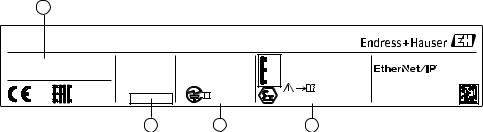
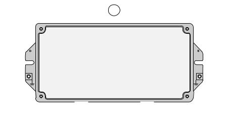
4.3Mounting the Fieldgate
In addition to fulfilling the conditions for good wireless communication, the mounting location should be well accessible for mounting and electrical installation. Make sure that there is enough space to open the housing cover and to access the terminals, switches, and cable glands. Choose a mounting location that meets the climatic limits specified and radio requirements in the technical data.
Required tools:
•2 screws (M6)
•Drill
•Screwdriver
2
1 |
1 |
2
Fig. 4-5: Mounting holes and housing screws
1 Mounting holes |
2 Housing screws |
Mounting the Fieldgate 1. Drill 2 holes in the mounting surface so that they match the holes of the housing (centers 240 mm to 250 mm apart). See the Technical Information document for "WirelessHART Fieldgate SWG70" (TI00027S).
2. Screw the device to the mounting surface.
Endress+Hauser |
19 |

Electrical Installation |
WirelessHART Fieldgate SWG70 |
|
|
5 Electrical Installation
5.1Connections and interfaces
The connections and interfaces are only accessible with an open enclosure. In the case of the DIP switches, the user has the choice of using the switch settings, or overriding the settings by software. See Chapter 8 "Fieldgate configuration" on page 42.
WARNING!
• If Fieldgate SWG70 is installed in a hazardous area Zone 2, you may only connect or disconnect the antenna and cables in the absence of any potentially explosive atmosphere or if the Fieldgate is not connected to the power supply.
5
2 |
3 |
4 |
6 |
1 |
1 |
7 |
|
Fig. 5-1: Connections and interfaces |
||
1 |
Grounding terminal |
5 |
Antenna |
2 |
RS-485 interfaces, duplicated terminal block for |
6 |
Antenna terminal |
|
daisy-chain capability |
7 |
Cable glands |
3Ethernet interface
4Power supply connections (redundant)
20 |
Endress+Hauser |
WirelessHART Fieldgate SWG70 |
Electrical Installation |
|
|
Connecting to 24 VDC power supply and grounding
5.2Connecting to power supply and grounding
There are two 24 VDC power supply terminal blocks located inside Fieldgate SWG70, allowing for redundant power supply. Open the housing cover to access the terminal blocks.
NOTICE!
•Ensure adequate strain relief for the cables.
•Pay attention to the bending radii of the cables. Do not drop below the permitted bending radii.
KL14 |
KL15 |
KL16 |
KL17 |
|
|
|
|
|
|
|
|
|
|
|
|
|
|
A |
B |
SHD |
A |
B |
SHD |
SHD T1 |
T2 |
RX– RX+ TX– TX+ |
+24V 0V |
+24V |
0V |
|
|
|
|
RS485 |
|
|
RS485 |
|
|
|
ETHERNET |
LINE1 |
LINE2 |
|
|
|
|
|
|
|
|
|
ON |
|
|
|
|
|
|
|
|
|
|
|
|
|
|
OFF |
|
|
|
|
|
|
+24V |
0V |
+24V |
0V |
|
|
|
|
|
|
|
|
|
|
|
LINE1 |
LINE2 |
|
|
|
|
|
|
|
|
|
|
|
||
1 |
|
2 |
3 |
|
|
|
|
|
|
|
|
|
|
3 |
|
|
Fig. 5-2: Power supply |
1 |
First power supply connection |
3 Grounding terminals |
2 |
Second (redundant) power supply connection |
|
Fieldgate SWG70 must be connected to a 24 VDC power supply. For details, see the Technical Information document for "WirelessHART Fieldgate SWG70" (TI00027S).
DANGER!
Risk of electric shock if the wrong power unit is used.
• Always use a SELV/PELV power unit to guarantee electrical safety.
1.Switch off the power supply.
2.Connect the protective ground to one of the two ground terminals.
3.Unscrew the 4 screws of the housing cover and remove the housing cover. See Figure 4-5 on page 19.
4.Route the 24 VDC power cable through the second cable gland from right. The permissible cable diameter lies between 6 mm and 10 mm.
5.Connect the 24 VDC power cable to the first power supply connection "Line 1" observing polarity. See Figure 5-1 on page 20.
6.If you want to connect a redundant power supply (optional), route the second 24 VDC power cable through the cable gland on the far right of the housing.
7.Connect the second power cable to the second power supply connection "Line 2" observing polarity.
8.Switch on the power supply. The green power LED should light up immediately.
9.Tighten the cable gland with appropriate torque. See Chapter 5.5 "Cable glands and housing cover" on page 25.
Endress+Hauser |
21 |

Electrical Installation |
WirelessHART Fieldgate SWG70 |
|
|
5.3Connecting to Ethernet
WARNING!
• If Fieldgate SWG70 is installed in a hazardous area Zone 2, you may only connect or disconnect the antenna and cables in the absence of any potentially explosive atmosphere or if the Fieldgate is not connected to the power supply.
NOTICE!
•Keep in mind that an access point of the Ethernet network has to be available. The maximum length of the cable running from the Fieldgate to the access point is 100 m, depending on the cable type and communication speed.
•Please note that older computers, hubs, switches or routers might not feature automatic TX/RX detection. In this case, use a crossover cable.
•Ensure adequate strain relief for the cables.
•Pay attention to the bending radii of the cables. Do not drop below the permitted bending radii.
5.3.1Connecting the "Modbus" or "Modbus + OPC" versions to Ethernet
The Ethernet cable is connected directly to the Ethernet terminal block in the Fieldgate.
KL7 |
KL8 |
KL9 |
KL10 |
KL11 |
KL12 |
KL13 |
|
|
|||||
|
|
|
|
|
|
|
|
|
|
|
|
|
|
|
|
|
|
|
|
|
|
|
|
|
|
|
|
|
|
|
|
|
|
|
|
|
|
|
|
|
|
|
|
|
|
|
|
|
|
|
|
|
|
|
|
A B SHD A B SHD
RS485 RS485
ON
OFF
SHD T1 T2 RX– RX+ TX– TX+
ETHERNET
SHD |
T1 |
T2 |
RX– RX+ TX– |
TX+ |
|
|
ETHERNET |
|
|
+24V |
0V |
+24V |
0V |
LINE1 |
LINE2 |
||
Fig. 5-3: Fieldgate with 5 cable entries and Ethernet terminal block
1.Switch off the power supply.
2.Unscrew the screws of the housing cover and remove the housing cover. See Figure 4-5 on page 19.
3.Route the Ethernet cable through the cable gland in the middle of the Fieldgate housing. The permissible cable diameter is between 6 mm and 10 mm.
22 |
Endress+Hauser |
WirelessHART Fieldgate SWG70 |
Electrical Installation |
|
|
4.Connect the Ethernet cable to the terminal block labeled "Ethernet" according to the following table.
|
|
|
|
|
|
|
|
|
|
|
|
|
|
|
|
|
Computer |
|
Fieldgate |
||
|
|
|
|
|
|
|
|
|
|
|
|
|
|
|
|
|
|
|
|
|
|
Pin Numbering |
|
|
|
|
|
Connector |
Crossover cable |
|
Normal cable |
||||||||||||
|
|
|
|
|
|
|
|
|
|
|
|
|
|
|
|
|
|
Pin 1 |
TX+ |
|
RX+ |
|
|
|
|
|
|
|
|
|
|
|
|
|
|
|
|
|
|
|
|
|
|
|
|
|
|
|
|
|
|
|
|
|
|
|
|
|
|
|
|
Pin 2 |
TX– |
|
RX– |
|
|
|
|
|
|
|
|
|
|
|
|
|
|
|
|
|
|
|
|
|
|
|
|
|
|
|
|
|
|
|
|
|
|
|
|
|
|
|
|
Pin 3 |
RX+ |
|
TX+ |
|
|
|
|
|
|
|
|
|
|
|
|
|
|
|
|
|
|
Pin 4 |
T2 |
|
T2 |
|
|
|
|
|
|
|
|
|
|
|
|
|
|
|
|
|
|
Pin 5 |
T2 |
|
T2 |
1 |
2 |
3 |
|
4 |
|
5 |
|
6 |
7 |
8 |
|
|
|
||||||||
|
|
|
|
|
|
|
|
|
|||||||||||||
|
|
|
|
|
|
|
|
|
|
|
|
|
|
|
|
|
|
Pin 6 |
RX– |
|
TX– |
|
|
|
|
|
|
|
|
|
|
|
|
|
|
|
|
|
|
|
|
|
|
|
|
|
|
|
|
|
|
|
|
|
|
|
|
|
|
|
|
Pin 7 |
T1 |
|
T1 |
|
|
|
|
|
|
|
|
|
|
|
|
|
|
|
|
|
|
|
|
|
|
|
|
|
|
|
|
|
|
|
|
|
|
|
|
|
|
|
|
Pin 8 |
T1 |
|
T1 |
|
|
|
|
|
|
|
|
|
|
|
|
|
|
|
|
|
|
|
|
|
|
5.Screw the housing cover on the housing.
6.Tighten the cable gland with appropriate torque. See Chapter 5.5 "Cable glands and housing cover" on page 25.
7.Switch on the power supply.
5.3.2Connecting the "EtherNet/IP" version to Ethernet
The Ethernet cable with a D-coded M12 connector is connected to the M12 socket of the
Fieldgate housing.
KL7 |
KL8 |
KL9 |
KL10 |
KL11 |
KL12 |
KL13 |
|
|
|||||
|
|
|
|
|
|
|
|
|
|
|
|
|
|
|
|
|
|
|
|
|
|
|
|
|
|
|
|
|
|
|
|
|
|
|
|
|
|
|
|
|
|
|
|
|
|
|
|
|
|
|
|
|
|
|
|
A B SHD A B SHD
RS485 RS485
ON
OFF
SHD T1 T2 RX– RX+ TX– TX+
ETHERNET
SHD |
T1 |
T2 |
|
|
E |
Fig. 5-4: Fieldgate with M12 socket in the middle
1Ethernet terminal block wired internally to M12 socket
2M12 socket, D-coded for connection to an Ethernet or Ethernet/IP network
1.Switch off the power supply.
2.Plug the D-coded M12 connector into the Ethernet socket of the Fieldgate. See Figure 5-4 on page 23.
3.Tighten the coupling nuts on the M12 connector. The Fieldgate is connected to the Ethernet network.
4.Switch on the power supply.
Endress+Hauser |
23 |

Electrical Installation |
|
|
|
|
WirelessHART Fieldgate SWG70 |
||
|
|
|
|
|
|||
Internal wiring |
The Ethernet socket is wired to the Ethernet terminal block. The internal wiring may not be |
||||||
|
modified. |
|
|
|
|
|
|
|
|
|
|
|
|
|
|
|
Pin Numbering |
|
Connector |
Signal |
|
Internal Wire Colors |
|
|
2 |
|
Pin 1 |
TX+ |
|
Yellow |
. |
|
|
|
|
|
|
|
|
|
|
|
Pin 2 |
RX+ |
|
White |
|
|
1 |
3 |
|
|
|
|
|
|
Pin 3 |
TX– |
|
Orange |
|
||
|
|
|
|
|
|
|
|
|
|
|
Pin 4 |
RX– |
|
Blue |
|
|
4 |
|
|
|
|
|
|
|
|
|
|
|
|
|
|
5.4Connecting to RS-485
Fieldgate SWG70 is equipped with a fully galvanic isolated RS-485 interface. A second RS-485 terminal block allows several Fieldgates to be connected through a daisy chain.
A terminating resistor is required at each end of the RS-485 cable. If the RS-485 cable is not routed to other devices (no daisy-chain connection), activate the terminating resistor using the corresponding DIP switches in the fieldgate. See Chapter 6.1.3 "DIP switches" on page 29.
NOTICE!
•The maximum length of the cable from the Fieldgate is 1200m (at reduced communication speed).
•Use shielded twisted pair (STP) cables only.
•If the cable shield is grounded, only connect the grounding to one cable end. This avoids potential equalization currents.
•Ensure adequate strain relief for the cables.
•Pay attention to the bending radii of the cables. Do not drop below the permitted bending radii.
KL1 |
KL2 |
KL3 |
KL4 |
KL5 |
KL6 |
A |
B |
SHD |
A |
B |
SHD |
|
RS485 |
|
|
RS485 |
|
|
1 |
|
|
2 |
|
A |
B |
SHD |
A |
B |
SHD |
|
RS485 |
|
|
RS485 |
|
ON |
OFF |
SHD T1 T2 RX– RX+ TX– TX+ |
+24V 0V |
+24V 0V |
ETHERNET |
LINE1 |
LINE2 |
Fig. 5-5: RS-485 interface
1 First RS-485 connection |
2 Second RS-485 connection for daisy chaining |
24 |
Endress+Hauser |

WirelessHART Fieldgate SWG70 |
Electrical Installation |
|
|
Connecting to RS-485 1. Switch off the power supply.
2.Unscrew the screws of the housing cover and remove the housing cover. See Figure 4-5 on page 19.
3.Route the RS-485 cable through the first cable gland from left. The permissible cable diameter is between 6 mm and 10 mm.
4.Connect the RS-485 cable to the left terminal block labeled "RS-485" as follows (see the graphic above):
Wire RS-485 cable |
Fieldgate terminal |
Remarks |
RxD/TxD– (RS-485 A) |
A |
RS-485 differential |
|
|
signal |
RxD/TxD+ (RS-485 B) |
B |
|
|
|
|
Shield |
SHD |
Cable shielding |
|
|
|
5.For a daisy-chain connection, route the second RS-485 cable through the second cable gland from left and connect it to the right terminal block labeled "RS-485", see table above.
6.To activate the RS-485 termination, set DIP switch number 7 to "ON". See Chapter 6.1.3 "DIP switches" on page 29.
7.Screw the housing cover on the housing.
8.Tighten the cable gland with appropriate torque. See Chapter 5.5 "Cable glands and housing cover" on page 25.
5.5Cable glands and housing cover
The degree of protection cannot be achieved if the cables and cable glands are not fitted correctly.
To ensure the IP degree of protection
•all screws of the housing / housing cover must have been tightened with the appropriate torque,
•only cables of the appropriate size must be used in the cable glands,
•all cable glands must be tightened with the appropriate torque,
•all seals must be undamaged and fitted correctly,
•all empty cable glands must be sealed with appropriate plugs.
The tightening torques of cable glands depend on what type of cable is used and must therefore be determined by the user. The cap nuts must be securely tightened. Tightening the cap nuts too tight can have a negative effect on the protection class. The following figures can be taken as rough guides.
Type of cable gland |
Approx. installation torque |
Plastic |
2.5 Nm |
Nickel-plated brass |
4.1 Nm |
Stainless steel |
4.1 Nm |
The Fieldgate housing cover must be tightened with a torque of 2.5 Nm.
Endress+Hauser |
25 |
Operation |
WirelessHART Fieldgate SWG70 |
|
|
6 Operation
6.1Operating and display elements
Inside the fieldgate housing there are LED indicators, DIP switches and reset buttons. The controls and indicators are accessible with open enclosure.
WARNING!
• If Fieldgate SWG70 is installed in a hazardous area Zone 2, you may only operate the DIP switches and the keys and only connect or disconnect the cables in the absence of any potentially explosive atmosphere or if the Fieldgate is not connected to the power supply.
1
2 |
3 |
4
|
|
|
|
|
|
|
|
|
|
|
|
|
|
|
|
|
|
|
|
|
|
|
|
|
|
|
|
|
|
|
|
|
|
|
|
|
|
|
|
|
|
|
|
|
|
|
|
|
|
|
|
|
|
Fig. 6-1: Operating and display elements |
|
|
|||||||
1 |
LEDs |
3 |
Button P2 |
|
|
||||||||||
2 |
Button P1 |
4 |
DIP switches |
|
|
||||||||||
26 |
Endress+Hauser |

WirelessHART Fieldgate SWG70 |
Operation |
|
|
6.1.1LEDs
Five LEDs indicate the status of Fieldgate SWG70.
1 |
2 |
3 |
4 |
5 |
A B SHD |
A B SHD |
SHD T1 T2 RX– RX+ TX– TX+ |
+24V 0V |
+24V 0V |
RS485 |
RS485 |
ETHERNET |
LINE1 |
LINE2 |
ON |
OFF |
|
|
|
|
|
|
|
|
|
|
|
|
|
|
|
|
|
|
|
|
|
|
|
|
|
|
|
|
|
|
|
|
|
|
|
|
|
|
|
|
|
|
|
|
|
|
|
|
|
|
|
|
|
|
|
|
|
|
|
|
|
|
|
|
|
|
|
|
|
|
|
|
|
|
|
Fig. 6-2: LED indicators |
||||||||||||||||||||
|
1 Yellow LED: RS-485 communication status |
4 Red LED: Device status |
|||||||||||||||||||||
|
2 Green LED: Power supply |
|
|
5 Yellow LED: Ethernet communication status |
|||||||||||||||||||
|
3 Yellow LED: WirelessHART communication status |
|
|
|
|
|
|
|
|
|
|
|
|
|
|
|
|
|
|
|
|||
Yellow LED: RS-485 |
|
|
|
|
|
|
|
|
|
|
|
|
|
|
|
|
|
|
|
|
|
|
|
Mode |
Status |
|
Meaning |
|
|
|
|
|
|
|
|
|
|
|
|
|
|
|
|
|
|
|
|
communication status |
|
|
|
|
|||||||||||||||||||
Flashes |
– |
|
Flashes briefly whenever a valid message is received by the |
||||||||||||||||||||
|
|
|
|
Fieldgate on the RS-485 communication line. |
|||||||||||||||||||
|
|
|
|
– The LED does not flash if the message is not addressed to the |
|||||||||||||||||||
|
|
|
|
Fieldgate or if a communication error was detected within the |
|||||||||||||||||||
|
|
|
|
message. |
|||||||||||||||||||
|
|
|
|
|
|||||||||||||||||||
|
Off |
– |
|
Currently no communication on the RS-485 line. |
|||||||||||||||||||
Green LED: Power supply |
|
|
|
|
|
|
|
|
|
|
|
|
|
|
|
|
|
|
|
|
|
|
|
|
|
|
|
|
|
|
|
|
|
|
|
|
|
|
|
|
|
|
|
|
|
|
|
Mode |
Status |
|
Meaning |
|
|
|
|
|
|
|
|
|
|
|
|
|
|
|
|
|
|
|
|
and operation status |
|
|
|
|
|||||||||||||||||||
On |
OK |
|
Fieldgate SWG70 is powered up and running |
||||||||||||||||||||
|
Flashes |
Not ready |
|
On power-up, indicates that the Fieldgate application is running |
|||||||||||||||||||
|
|
|
|
but the Fieldgate is not yet ready to answer HART commands. |
|||||||||||||||||||
|
|
|
|
|
|||||||||||||||||||
|
Off |
No power |
|
The power supply is not connected/Fieldgate is not ready. |
|||||||||||||||||||
Yellow LED: WirelessHART |
|
|
|
|
|
|
|
|
|
|
|
|
|
|
|
|
|
|
|
|
|
|
|
|
|
|
|
|
|
|
|
|
|
|
|
|
|
|
|
|
|
|
|
|
|
|
|
Mode |
Status |
|
Meaning |
|
|
|
|
|
|
|
|
|
|
|
|
|
|
|
|
|
|
|
|
communication status |
|
|
|
|
|||||||||||||||||||
Flashes |
– |
|
Flashes shortly whenever a valid WirelessHART message is |
||||||||||||||||||||
|
|
|
|
received by the Fieldgate on the WirelessHART communication |
|||||||||||||||||||
|
|
|
|
interface. |
|
|
|
|
|
|
|
|
|
|
|
|
|
|
|
|
|
|
|
|
|
|
|
– Messages include simple commands but not published bursts |
|||||||||||||||||||
|
|
|
|
and event notifications. |
|||||||||||||||||||
|
|
|
|
|
|||||||||||||||||||
|
Off |
– |
|
Currently no communication on the WirelessHART interface. |
|||||||||||||||||||
Red LED: Device status |
|
|
|
|
|
|
|
|
|
|
|
|
|
|
|
|
|
|
|
|
|
|
|
|
|
|
|
|
|
|
|
|
|
|
|
|
|
|
|
|
|
|
|
|
|
|
|
Mode |
Status |
|
Meaning |
|
|
|
|
|
|
|
|
|
|
|
|
|
|
|
|
|
|
|
|
|
On |
Hardware fault |
|
Fieldgate has detected a hardware fault that makes normal |
|||||||||||||||||||
|
|
|
|
operation impossible. |
|||||||||||||||||||
|
|
|
|
|
|||||||||||||||||||
|
Flashes |
Recovering from hardware |
|
The Fieldgate application is trying to recover from the fault (not |
|||||||||||||||||||
|
|
fault. |
|
possible for all faults). |
|||||||||||||||||||
|
|
|
|
|
|
|
|
|
|
|
|
|
|
|
|
|
|
|
|
|
|
|
|
|
Off |
No hardware fault |
|
– |
|
|
|
|
|
|
|
|
|
|
|
|
|
|
|
|
|
|
|
|
|
|
|
|
|
|
|
|
|
|
|
|
|
|
|
|
|
|
|
|
|
|
|
Endress+Hauser |
27 |

Operation |
WirelessHART Fieldgate SWG70 |
|
|
Yellow LED: Ethernet communication status
Mode |
Status |
Meaning |
On |
– |
The connection to the Ethernet line is established. |
|
|
|
Flashing |
– |
Fieldgate is receiving a message via the Ethernet interface. The |
irregularly |
|
LED does not flash in the following instances: |
|
|
• The message is not addressed to the Fieldgate. |
|
|
• A communication error was detected in the message. |
|
|
|
Flashing (every |
– |
A conflict has been detected in the IP address. The Fieldgate IP |
second) |
|
address is already being used by another device in the Ethernet |
|
|
network |
|
|
Assign another IP address to the Fieldgate. See Chapter 7.1 |
|
|
"Ethernet connection" on page 31. |
|
|
|
Off |
– |
There is no connection to the Ethernet network. This is often due |
|
|
to a bad cable connection. See Chapter 5.3 "Connecting to Ethernet" |
|
|
on page 22. |
|
|
|
6.1.2Buttons
Fieldgate has two pushbuttons.
WARNING!
•When Fieldgate SWG70 is installed in Ex-Zone 2 and the power is switched on, the operation of the pushbuttons is permitted only in the absence of any potentially explosive atmosphere.
1 2
A B SHD |
A B SHD |
SHD T1 T2 RX– RX+ TX– TX+ |
+24V 0V |
+24V 0V |
RS485 |
RS485 |
ETHERNET |
LINE1 |
LINE2 |
ON |
OFF |
1 2 3 4 5 6 7 8
Fig. 6-3: Pushbuttons
1 Button P1 |
2 Button P2 |
28 |
Endress+Hauser |

WirelessHART Fieldgate SWG70 |
Operation |
|
|
The function of the buttons is as follows:
Buttons |
|
|
|
|
Buttons |
Function |
Procedure |
||
|
Button P1 |
Configuration reset |
Press the button for more than 3 seconds. |
|
|
|
|
– All Fieldgate SWG70 configuration parameters are reset to |
|
|
|
|
|
factory settings with exception of the parameters set by button |
|
|
|
|
P2 and button P1 + P2. |
|
|
|
– |
After approx. 3 seconds, all LEDs light up to confirm the reset. |
|
|
|
|
|
|
Button P2 |
Communication reset |
Press the button for more than 3 seconds. |
|
|
|
|
– All Fieldgate SWG70 configuration parameters related to the |
|
|
|
|
|
wired communication channels are reset to factory settings. |
|
|
|
– |
After approx. 3 seconds, all LEDs light up to confirm the reset. |
|
|
|
|
|
|
Button P1 + P2 |
Password reset |
Press buttons P1 and P2 simultaneously for more than 3 seconds. |
|
|
DIP switch 8 OFF |
|
– All Fieldgate SWG70 passwords are reset to the factory settings. |
|
|
|
|
– Passwords are used for access to the Command Line Interface |
|
|
|
|
|
and the Web Server (HTTPS). |
|
|
|
– For Web Server User name: admin; Password: admin |
|
|
|
|
– |
After approx. 3 seconds, all LEDs light up to confirm the reset. |
|
|
|
|
|
|
Button P1 + P2 |
Network manager reset |
Press buttons P1 and P2 simultaneously for more than 3 seconds. |
|
|
DIP switch 8 ON |
|
– The Fieldgate SWG70 join key, network ID, radio power and |
|
|
|
|
|
access mode are reset to factory settings. |
|
|
|
– |
After approx. 3 seconds, all LEDs light up to confirm the reset. |
|
|
|
|
|
6.1.3DIP switches
WARNING!
• When Fieldgate SWG70 is installed in Ex-Zone 2 and connected to the power supply, the operation of DIP switches is permitted only in the absence of any potentially explosive atmosphere.
NOTICE!
•The same functions can be initiated from the Fieldgate SWG70 Web interface and DTM. See Chapter 8.3 "Interfaces (wired communication)" on page 48.
Fieldgate SWG70 has one 8-gang DIP switch. Fieldgate SWG70 is delivered with all DIP switches set to ON and with all DIP switch functions set by software controls.
ON |
|
|
|
|
|
|
|
OFF |
|
|
|
|
|
|
|
1 |
2 |
3 |
4 |
5 |
6 |
7 |
8 |
A B SHD |
A B SHD |
SHD T1 T2 RX– RX+ TX– TX+ |
+24V 0V |
+24V 0V |
RS485 |
RS485 |
ETHERNET |
LINE1 |
LINE2 |
ON |
OFF |
1 2 3 4
|
Fig. 6-4: DIP switches |
||
1 |
DIP switches 1 to 4: HART device address |
3 |
DIP switch 7: RS-485 terminating resistor |
2 |
DIP switches 5 and 6: |
4 |
DIP switch 8: Security mode |
|
Baud rate of RS-485 interface |
|
|
Endress+Hauser |
29 |

Operation |
|
|
|
|
|
|
|
WirelessHART Fieldgate SWG70 |
|||||
|
|
|
|
|
|
|
|
|
|
|
|
|
|
DIP switch positions |
|
|
|
|
|
|
|
|
|
|
|
|
|
Switch |
Function |
1 |
2 |
3 |
4 |
Value |
1 |
2 |
3 |
4 |
Value |
||
|
1 – 4 |
HART device address 1) |
OFF |
OFF |
OFF |
OFF |
0 |
|
OFF |
OFF |
OFF |
ON |
8 |
|
|
|
ON |
OFF |
OFF |
OFF |
1 |
|
ON |
OFF |
OFF |
ON |
9 |
|
|
|
|
|
|
|
|
|
|
|
|
|
|
|
|
|
OFF |
ON |
OFF |
OFF |
2 |
|
OFF |
ON |
OFF |
ON |
10 |
|
|
|
|
|
|
|
|
|
|
|
|
|
|
|
|
|
ON |
ON |
OFF |
OFF |
3 |
|
ON |
ON |
OFF |
ON |
11 |
|
|
|
|
|
|
|
|
|
|
|
|
|
|
|
|
|
OFF |
OFF |
ON |
OFF |
4 |
|
OFF |
OFF |
ON |
ON |
12 |
|
|
|
|
|
|
|
|
|
|
|
|
|
|
|
|
|
ON |
OFF |
ON |
OFF |
5 |
|
ON |
OFF |
ON |
ON |
13 |
|
|
|
|
|
|
|
|
|
|
|
|
|
|
|
|
|
OFF |
ON |
ON |
OFF |
6 |
|
OFF |
ON |
ON |
ON |
14 |
|
|
|
|
|
|
|
|
|
|
|
|
|
|
|
|
|
ON |
ON |
ON |
OFF |
7 |
|
ON |
ON |
ON |
ON |
15 |
|
|
|
|
|
|
|
|
|
|
|
|
|
|
|
|
|
5 |
6 |
Value |
|
|
|
5 |
6 |
Value |
|
|
|
5 and 6 |
Baud rate of RS-485 |
OFF |
OFF |
9600 bit/s |
|
|
OFF |
ON |
38400 bit/s |
|
||
|
|
interface |
|
|
|
|
|
|
|
|
|
||
|
|
ON |
OFF |
19200 bit/s |
|
|
ON |
ON |
57600 bit/s |
|
|||
|
|
|
|
|
|
|
|
|
|
|
|
|
|
|
7 |
RS-485 termination |
• OFF |
= disconnected |
|
|
• ON = connected |
|
|
||||
|
|
|
|
|
|
|
|
|
|
||||
|
8 |
Download |
• OFF = disabled |
|
|
|
• ON = enabled |
|
|
||||
|
|
Join Key/Network ID |
|
|
|
|
|
|
|
|
|
|
|
|
|
|
|
|
|
|
|
|
|
|
|||
|
1) You can set |
up HART device addresses |
from 0 to 63 by software. |
|
|
|
|
|
|
|
|||
Security mode |
|
|
|
|
|
|
|
|
|
|
|
|
|
When DIP switch 8 is OFF, it is not possible to download the Network ID and the Join Key to |
|||||||||||||
|
the Fieldgate. See Chapter 8.3.2 "Serial (RS-485)" on page 49. Fieldgate SWG70 is delivered |
||||||||||||
|
with the download enabled by default, i.e. DIP switch 8 is ON. |
|
|
|
|
||||||||
30 |
Endress+Hauser |
Loading...