


 Loading...
BA01049F/00/EN/07.18
71394698
2018-04-12
01.02.zz (Device firmware)
Products |
Solutions |
Services |
|
|
|
Operating Instructions
Micropilot FMR51, FMR52
HART
Free space radar

Micropilot FMR51, FMR52 HART
|
|
|
|
|
|
|
|
|
|
|
|
|
|
|
|
|
|
|
|
|
|
|
|
|
|
|
|
|
|
|
|
|
|
|
|
|
|
|
|
|
|
|
|
|
ORDER CODE: |
|
|
|
|
|
|
|
|
|
|
|
|
|
|
|
|
|
|
|
|
XXXXX-XXXXXX |
|
|
|
|
|
|
|
|
|
|
|
|
|
|
|
||
1. |
|
|
SER. NO.: |
|
|
|
|
|
|
|
|
|
|
|
|
|
|
|
|
|
|
XXXXXXXXXXXX |
|
|
|
|
|
|
|
|
|
|
|
|
|
|
|
||||
|
|
|
EXT. ORD. CD.: |
|
|
|
|
|
|
|
|
|
|
|
|
|
|
|
|
|
|
|
|
XXX.XXXX.XX |
|
|
|
|
|
|
|
|
|
|
|
|
|
|
|
||
|
|
|
|
|
|
|
|
|
|
|
|
|
|
|
|
|
|
|
|
|
|
|
|
|
|
|
|
|
|
|
|
|
|
|
|
|
|
|
|
|
|
|
|
|
|
|
|
|
|
|
|
|
|
|
|
|
|
|
|
|
|
|
|
|
|
|
|
|
|
|
|
|
|
|
|
|
|
|
|
|
|
|
|
|
|
|
|
|
|
|
|
|
|
|
|
|
|
|
|
|
|
|
|
|
|
|
|
|
|
|
|
|
|
|
|
|
|
|
|
|
|
|
|
|
|
|
|
|
|
|
|
|
|
|
|
|
|
|
|
|
|
|
|
|
|
|
|
|
|
Serial number |
|
|
|
|
|
|
|
|
|
|
|
|
|
|
|
|
|
|||||
|
|
|
|
|
|
|
|
|
|
|
|
|
2. |
www.endress.com/deviceviewer |
|
|
|
|
|
Endress+Hauser |
|||||
|
|
|
|
|
|
|
|
|
|
|
Operations App |
|
|
|
|
|
|
|
|
|
|
|
|
|
|
|
|
|
|
|
|
|
|
|
|
|
|
|
|
|
|
|
|
|
|
|
|
|
|
|
|
|
|
|
|
|
|
|
|
|
|
|
|
|
|
|
|
|
|
|
|
|
|
|
|
|
|
|
|
|
|
|
|
|
|
|
|
|
|
|
3.
A0023555
2 |
Endress+Hauser |

Micropilot FMR51, FMR52 HART |
Table of contents |
|
|
Table of contents
1Wichtige Hinweise zum
Dokument . . . . . . . . . . . . . . . . . . . . . . . . . 5
1.1 |
Document function . . . . . . . . . . . . . . . . . . . . . |
5 |
|
1.2 |
Symbols |
. . . . . . . . . . . . . . . . . . . . . . . . . . . . . . |
5 |
|
1.2.1 |
Safety symbols . . . . . . . . . . . . . . . . . . |
5 |
|
1.2.2 |
Electrical symbols . . . . . . . . . . . . . . . . |
5 |
|
1.2.3 |
Tool symbols . . . . . . . . . . . . . . . . . . . . |
5 |
|
1.2.4 |
Symbols for |
|
|
|
certain types of information . . . . . . . . . |
6 |
|
1.2.5 |
Symbols in graphics . . . . . . . . . . . . . . . |
6 |
|
1.2.6 Symbols at the device . . . . . . . . . . . . . |
7 |
|
1.3 |
Additional documentation . . . . . . . . . . . . . . . . |
7 |
|
1.4 |
Terms and abbreviations . . . . . . . . . . . . . . . . . |
8 |
|
1.5 |
Registered trademarks . . . . . . . . . . . . . . . . . . . |
9 |
|
2 |
Basic safety instructions . . . . . . . . . . . |
10 |
|
2.1 |
Requirements for the personnel . . . . . . . . . . . |
10 |
|
2.2 |
Designated use . . . . . . . . . . . . . . . . . . . . . . . |
10 |
|
2.3 |
Workplace safety . . . . . . . . . . . . . . . . . . . . . . |
11 |
|
2.4 |
Operational safety . . . . . . . . . . . . . . . . . . . . . |
11 |
|
2.5 |
Product safety . . . . . . . . . . . . . . . . . . . . . . . . |
11 |
|
|
2.5.1 |
CE mark . . . . . . . . . . . . . . . . . . . . . . |
11 |
|
2.5.2 |
EAC conformity . . . . . . . . . . . . . . . . . |
12 |
2.6 |
Safety Instructions (XA) . . . . . . . . . . . . . . . . . |
12 |
|
3 |
Product description . . . . . . . . . . . . . . . . |
15 |
|
3.1 |
Product design . . . . . . . . . . . . . . . . . . . . . . . . |
15 |
|
|
3.1.1 |
Micropilot FMR51 . . . . . . . . . . . . . . . |
15 |
|
3.1.2 |
Micropilot FMR52 . . . . . . . . . . . . . . . |
15 |
|
3.1.3 |
Electronics housing . . . . . . . . . . . . . . |
16 |
4Incoming acceptance and product
|
identification . . . . . . . . . . . . . . . . . . . . . |
17 |
4.1 |
Incoming acceptance . . . . . . . . . . . . . . . . . . . |
17 |
4.2 |
Product identification . . . . . . . . . . . . . . . . . . |
17 |
|
4.2.1 Nameplate . . . . . . . . . . . . . . . . . . . . |
18 |
5 |
Storage, Transport . . . . . . . . . . . . . . . . |
19 |
|
5.1 |
Storage conditions . . . . . . . . . . . . . . . . . . . . . |
19 |
|
5.2 |
Transport product to the measuring point . . . . |
19 |
|
6 |
Installation . . . . . . . . . . . . . . . . . . . . . . . |
20 |
|
6.1 |
Installation conditions . . . . . . . . . . . . . . . . . . |
20 |
|
|
6.1.1 |
Mounting position . . . . . . . . . . . . . . . |
20 |
|
6.1.2 |
Vessel installations . . . . . . . . . . . . . . |
21 |
|
6.1.3 Reduction of interference echoes . . . . |
21 |
|
|
6.1.4 Measurement in a plastic vessel . . . . . |
22 |
|
|
6.1.5 |
Optimization options . . . . . . . . . . . . . |
22 |
|
6.1.6 |
Beam angle . . . . . . . . . . . . . . . . . . . . |
23 |
6.2 |
Measuring conditions . . . . . . . . . . . . . . . . . . |
24 |
|
6.3 |
Mounting cladded flanges . . . . . . . . . . . . . . . |
25 |
|
Endress+Hauser
6.4 |
Installation in vessel (free space) . . . . . . . . . . |
26 |
|
|
6.4.1 |
Horn antenna (FMR51) . . . . . . . . . . . |
26 |
|
6.4.2 Measurement from the outside |
|
|
|
|
through plastic walls (FMR50/ |
|
|
|
FMR51) . . . . . . . . . . . . . . . . . . . . . . |
28 |
|
6.4.3 Horn antenna, flush mount |
|
|
|
|
(FMR52) . . . . . . . . . . . . . . . . . . . . . . |
29 |
6.5 |
Installation in stilling well . . . . . . . . . . . . . . . |
30 |
|
|
6.5.1 Recommendations for the stilling |
|
|
|
|
well . . . . . . . . . . . . . . . . . . . . . . . . . |
30 |
|
6.5.2 Examples for the construction of |
|
|
|
|
stilling wells . . . . . . . . . . . . . . . . . . . |
31 |
6.6 |
Installation in bypass . . . . . . . . . . . . . . . . . . . |
32 |
|
|
6.6.1 Recommendations for the bypass |
|
|
|
|
pipe . . . . . . . . . . . . . . . . . . . . . . . . . |
32 |
|
6.6.2 Example for the construction of a |
|
|
|
|
bypass . . . . . . . . . . . . . . . . . . . . . . . |
33 |
6.7 |
Container with heat insulation . . . . . . . . . . . . |
34 |
|
6.8 |
Turning the transmitter housing . . . . . . . . . . |
34 |
|
6.9 |
Turning the display . . . . . . . . . . . . . . . . . . . . |
35 |
|
|
6.9.1 |
Opening cover . . . . . . . . . . . . . . . . . . |
35 |
|
6.9.2 Turning the display module . . . . . . . . |
35 |
|
|
6.9.3 |
Closing electronics compartment |
|
|
|
cover . . . . . . . . . . . . . . . . . . . . . . . . |
36 |
6.10 |
Post-installation check . . . . . . . . . . . . . . . . . . |
36 |
|
7 |
Electrical connection . . . . . . . . . . . . . . |
37 |
|
7.1 |
Connection conditions . . . . . . . . . . . . . . . . . . |
37 |
|
|
7.1.1 |
Terminal assignment . . . . . . . . . . . . |
37 |
|
7.1.2 |
Cable specification . . . . . . . . . . . . . . . |
43 |
|
7.1.3 |
Device plug connectors . . . . . . . . . . . |
44 |
|
7.1.4 |
Supply voltage . . . . . . . . . . . . . . . . . . |
45 |
|
7.1.5 |
Overvoltage protection . . . . . . . . . . . |
47 |
7.2 |
Connecting the measuring device . . . . . . . . . . |
47 |
|
|
7.2.1 |
Opening connection compartment |
|
|
|
cover . . . . . . . . . . . . . . . . . . . . . . . . |
48 |
|
7.2.2 |
Connecting . . . . . . . . . . . . . . . . . . . . |
48 |
|
7.2.3 |
Plug-in spring-force terminals . . . . . . |
49 |
|
7.2.4 |
Closing connection compartment |
|
|
|
cover . . . . . . . . . . . . . . . . . . . . . . . . |
49 |
7.3 |
Post-connection check . . . . . . . . . . . . . . . . . . |
50 |
|
8 |
Operation options . . . . . . . . . . . . . . . . . |
51 |
|
8.1 |
Overview . . . . . . . . . . . . . . . . . . . . . . . . . . . . |
51 |
|
|
8.1.1 |
Local operation . . . . . . . . . . . . . . . . . |
51 |
|
8.1.2 |
Operation with remote display and |
|
operating module FHX50 . . . . . . . . . . 52
8.1.3Operation via Bluetooth® wireless
technology . . . . . . . . . . . . . . . . . . . . 53 8.1.4 Remote operation . . . . . . . . . . . . . . . 54
8.2Structure and function of the operating
menu . . . . . . . . . . . . . . . . . . . . . . . . . . . . . . 55 8.2.1 Structure of the operating menu . . . . 55
3

Table of contents |
|
|
Micropilot FMR51, FMR52 HART |
|||
|
|
|
|
|
||
8.2.2 User roles and related access |
|
|
13.6.2 Filtering the event logbook . . . . . . . . |
93 |
||
|
authorization . . . . . . . . . . . . . . . . . . |
57 |
|
13.6.3 Overview of information events . . . . . |
93 |
|
8.2.3 |
Data access - Security . . . . . . . . . . . . |
57 |
13.7 |
Firmware history . . . . . . . . . . . . . . . . . . . . . . |
94 |
|
8.3 Display and operating module . . . . . . . . . . . . |
62 |
|
|
|
||
8.3.1 |
Display appearance . . . . . . . . . . . . . . |
62 |
14 |
Maintenance . . . . . . . . . . . . . . . . . . . . . . |
95 |
|
8.3.2 |
Operating elements . . . . . . . . . . . . . . |
65 |
14.1 |
Exterior cleaning |
95 |
|
8.3.3 Entering numbers and text |
66 |
|||||
14.2 |
Replacing seals |
95 |
||||
8.3.4 Opening the context menu |
68 |
|||||
|
|
|
||||
8.3.5Envelope curve on the display and
|
|
operating module . . . . . . . . . . . . . . . |
69 |
15 |
Repairs . . . . . . . . . . . . . . . . . . . . . . . . . . . |
96 |
||
9 |
System integration via HART |
|
15.1 |
General information on repairs . . . . . . . . . . . |
. 96 |
|||
|
|
15.1.1 |
Repair concept . . . . . . . . . . . . . . . . . |
96 |
||||
|
protocol . . . . . . . . . . . . . . . . . . . . . . . . . . |
70 |
|
15.1.2 Repairs to Ex-approved devices . . . . . |
96 |
|||
9.1 |
Overview of the Device Description files |
|
|
15.1.3 Replacement of an electronics |
|
|||
|
|
|
module . . . . . . . . . . . . . . . . . . . . . . . |
96 |
||||
|
(DD) . . |
. . . . . . . . . . . . . . . . . . . . . . . . . . . . . |
70 |
|
15.1.4 Replacement of a device . . . . . . . . . . |
96 |
||
9.2 |
Measured values via HART protocol . . . . . . . . |
70 |
15.2 |
Spare parts . . . . . . . . . . . . . . . . . . . . . . . . . . |
97 |
|||
10 |
Commissioning via SmartBlue |
|
15.3 |
Return . |
. . . . . . . . . . . . . . . . . . . . . . . . . . . . |
. 97 |
||
|
15.4 |
Disposal |
. . . . . . . . . . . . . . . . . . . . . . . . . . . . |
97 |
||||
|
(app) . |
. . . . . . . . . . . . . . . . . . . . . . . . . . . . |
71 |
16 |
Accessories |
98 |
||
10.1 |
Requirements |
71 |
||||||
16.1 |
Device-specific accessories |
98 |
||||||
10.2 |
Commissioning . . . . . . . . . . . . . . . . . . . . . . . |
71 |
||||||
|
|
|
|
|
16.1.1 |
Weather protection cover . . . . . . . . . |
98 |
|
11 |
Commissioning via wizard |
75 |
|
16.1.2 |
Remote display FHX50 . . . . . . . . . . . |
99 |
||
|
16.1.3 Horn protection for horn antenna |
100 |
||||||
|
|
|
|
|
||||
12 |
Commissioning via operating |
|
|
16.1.4 Horn protection for horn antenna |
|
|||
|
|
|
with variable antenna extension . . . |
101 |
||||
|
menu . |
. . . . . . . . . . . . . . . . . . . . . . . . . . . . |
76 |
|
16.1.5 |
Overvoltage protection . . . . . . . . . . |
102 |
|
12.1 |
Installation and function check |
76 |
|
16.1.6 |
Gas-tight feedthrough . . . . . . . . . . . |
102 |
||
|
16.1.7 Bluetooth module for HART devices |
103 |
||||||
12.2 |
Setting the operating language . . . . . . . . . . . . |
76 |
16.2 |
Communication-specific accessories . . . . . . . |
104 |
|||
12.3 |
Configuration of a level measurement . . . . . . |
77 |
16.3 |
Service-specific accessories . . . . . . . . . . . . . . |
105 |
|||
12.4 |
Recording the reference curve . . . . . . . . . . . . |
79 |
16.4 |
System components . . . . . . . . . . . . . . . . . . . |
106 |
|||
12.5 |
Configuration of the on-site display . . . . . . . . |
80 |
|
|
|
|
||
|
12.5.1 Factory settings of the on-site |
|
17 |
Operating menu |
107 |
|||
|
|
display |
80 |
|||||
|
|
17.1 |
Overview of the operating menu |
|
||||
|
12.5.2 Adjustment of the on-site display . . . |
80 |
|
|||||
12.6 |
Configuration of the current outputs . . . . . . . . |
80 |
|
(SmartBlue) . . . . . . . . . . . . . . . . . . . . . . . . . |
107 |
|||
|
12.6.1 Factory setting of the current |
|
17.2 |
Overview of the operating menu (display |
|
|||
|
|
outputs . . . . . . . . . . . . . . . . . . . . . . . |
80 |
|
module) |
. . . . . . . . . . . . . . . . . . . . . . . . . . . |
112 |
|
|
12.6.2 Adjustment of the current outputs . . . |
80 |
17.3 |
Overview of the operating menu (operating |
|
|||
12.7 |
Configuration management . . . . . . . . . . . . . . |
81 |
|
tool) . . . |
. . . . . . . . . . . . . . . . . . . . . . . . . . . |
119 |
||
12.8 |
Protection of the settings against |
|
17.4 |
"Setup" menu . . . . . . . . . . . . . . . . . . . . . . . . |
125 |
|||
|
unauthorized changes . . . . . . . . . . . . . . . . . . |
82 |
|
17.4.1 |
"Mapping" wizard . . . . . . . . . . . . . . . |
133 |
||
|
|
|
|
|
17.4.2 |
"Advanced setup" submenu . . . . . . . . |
135 |
|
13 |
Diagnostics and troubleshooting . . . |
83 |
17.5 |
"Diagnostics" menu . . . . . . . . . . . . . . . . . . . . |
180 |
|||
13.1 |
General trouble shooting |
83 |
|
17.5.1 |
"Diagnostic list" submenu . . . . . . . . . |
182 |
||
|
17.5.2 |
"Event logbook" submenu . . . . . . . . . |
183 |
|||||
|
13.1.1 |
General errors . . . . . . . . . . . . . . . . . . |
83 |
|
17.5.3 |
"Device information" submenu . . . . . |
184 |
|
|
13.1.2 |
Error - SmartBlue operation . . . . . . . . |
84 |
|
17.5.4 |
"Measured values" submenu . . . . . . . |
187 |
|
|
13.1.3 |
Parametrization errors . . . . . . . . . . . |
84 |
|
17.5.5 |
"Data logging" submenu . . . . . . . . . . |
189 |
|
13.2 |
Diagnostic information on local display . . . . . . |
86 |
|
17.5.6 |
"Simulation" submenu . . . . . . . . . . . |
192 |
||
|
13.2.1 |
Diagnostic message . . . . . . . . . . . . . . |
86 |
|
17.5.7 |
"Device check" submenu . . . . . . . . . . |
197 |
|
13.3 |
13.2.2 Calling up remedial measures . . . . . . |
88 |
|
17.5.8 |
"Heartbeat" submenu . . . . . . . . . . . . |
199 |
||
Diagnostic event in the operating tool . . . . . . . |
89 |
|
|
|
|
|||
13.4 |
Diagnostic list . . . . . . . . . . . . . . . . . . . . . . . . |
90 |
Index |
|
200 |
|||
13.5 |
Overview of diagnostic events |
91 |
. . . . . . . . . . . . . . . . . . . . . . . . . . . |
|||||
|
|
|
|
|||||
13.6 |
Event logbook . . . . . . . . . . . . . . . . . . . . . . . . |
92 |
|
|
|
|
||
|
13.6.1 |
Event history . . . . . . . . . . . . . . . . . . . |
92 |
|
|
|
|
|
4 |
|
|
|
|
|
Endress+Hauser |
||

Micropilot FMR51, FMR52 HART |
Wichtige Hinweise zum Dokument |
|
|
1Wichtige Hinweise zum Dokument
1.1Document function
These Operating Instructions contain all the information that is required in various phases of the life cycle of the device: from product identification, incoming acceptance and storage, to mounting, connection, operation and commissioning through to troubleshooting, maintenance and disposal.
1.2Symbols
1.2.1Safety symbols
Symbol Meaning
DANGER!
 DANGER This symbol alerts you to a dangerous situation. Failure to avoid this situation will result in serious or fatal injury.
WARNING!
 WARNING This symbol alerts you to a dangerous situation. Failure to avoid this situation can result in serious or fatal injury.
CAUTION!
 CAUTION This symbol alerts you to a dangerous situation. Failure to avoid this situation can result in minor or medium injury.
NOTE!
NOTICE This symbol contains information on procedures and other facts which do not result in personal injury.
1.2.2Electrical symbols
Symbol Meaning
Direct current
Alternating current
Direct current and alternating current
Ground connection
A grounded terminal which, as far as the operator is concerned, is grounded via a grounding system.
Protective Earth (PE)
A terminal which must be connected to ground prior to establishing any other connections.
The ground terminals are situated inside and outside the device:
•Inner ground terminal: Connects the protectiv earth to the mains supply.
•Outer ground terminal: Connects the device to the plant grounding system.
1.2.3Tool symbols
Symbol Meaning
Torx screwdriver
A0013442
Flat blade screwdriver
A0011220
Endress+Hauser |
5 |

Wichtige Hinweise zum Dokument |
Micropilot FMR51, FMR52 HART |
Symbol |
Meaning |
|
Cross-head screwdriver |
A0011219 |
|
|
Allen key |
A0011221
Hexagon wrench
A0011222
1.2.4Symbols for certain types of information
|
Symbol |
Meaning |
|||||
|
|
|
|
|
|
|
|
|
|
|
|
|
|
|
Permitted |
|
|
|
|
|
|
|
Procedures, processes or actions that are permitted. |
|
|
|
|
|
|
|
|
|
|
|
|
|
|
|
Preferred |
|
|
|
|
|
|
|
Procedures, processes or actions that are preferred. |
|
|
|
|
|
|
|
|
|
|
|
|
|
|
|
Forbidden |
|
|
|
|
|
|
|
Procedures, processes or actions that are forbidden. |
|
|
|
|
|
|
|
|
|
|
|
|
|
|
|
Tip |
|
|
|
|
|
|
|
Indicates additional information. |
|
|
|
|
|
|
|
|
|
|
|
|
|
|
|
Reference to documentation. |
|
|
|
|
|
|
|
|
|
|
|
|
|
|
|
|
|
|
|
|
|
|||
|
|
|
A |
Reference to page. |
|||
|
|
|
|
|
|
|
|
|
|
|
|
|
|
|
|
|
|
|
|
|
|
|
|
|
|
|
|
|
|
|
Reference to graphic. |
|
|
|
|
|
|
|
|
|
|
|
|
|
|
|
|
|
|
|
|
|
|
|
Notice or individual step to be observed. |
|
|
|
|
|
|
|
|
|
|
, |
|
, |
|
… |
Series of steps. |
|
1. |
2. |
3. |
||||
|
|
|
|
|
|
|
|
|
|
|
|
|
|
|
Result of a step. |
|
|
|
|
|
|
|
|
|
|
|
|
|
|
|
Help in the event of a problem. |
|
|
|
|
|
|
|
|
|
|
|
|
|
|
|
Visual inspection. |
|
|
|
|
|
|
|
|
1.2.5Symbols in graphics
|
Symbol |
Meaning |
|||||
|
|
|
|
|
|
|
|
1, 2, 3 ... |
Item numbers |
||||||
|
|
|
|
|
|
|
|
|
|
, |
|
, |
|
… |
Series of steps |
|
1. |
2. |
3. |
||||
|
|
|
|||||
|
A, B, C, ... |
Views |
|||||
|
|
||||||
A-A, B-B, C-C, ... |
Sections |
||||||
|
|
|
|
|
|
|
|
- |
|
Hazardous area |
|||||
|
Indicates a hazardous area. |
||||||
|
|
|
|
|
|
|
|
|
|
|
|
|
|
|
|
. |
|
Safe area (non-hazardous area) |
|||||
|
Indicates the non-hazardous area. |
||||||
|
|
|
|
|
|
|
|
|
|
|
|
|
|
|
|
6 |
Endress+Hauser |

Micropilot FMR51, FMR52 HART |
Wichtige Hinweise zum Dokument |
|
|
1.2.6Symbols at the device
Symbol Meaning
Safety instructions
Observe the safety instructions contained in the associated Operating Instructions.
Temperature resistance of the connection cables
Specifies the minimum value of the temperature resistance of the connection cables.
1.3Additional documentation
Document |
Purpose and content of the document |
|
|
Technical Information |
Planning aid for your device |
TI01040F (FMR51, FMR52) |
The document contains all the technical data on the device and provides |
|
an overview of the accessories and other products that can be ordered for |
|
the device. |
|
|
Brief Operating Instructions |
Guide that takes you quickly to the 1st measured value |
KA01100F (FMR51/FMR52, |
The Brief Operating Instructions contain all the essential information |
HART) |
from incoming acceptance to initial commissioning. |
|
|
Description of Device Parameters |
Reference for your parameters |
GP01014F (FMR5x, HART) |
The document provides a detailed explanation of each individual |
|
parameter in the operating menu. The description is aimed at those who |
|
work with the device over the entire life cycle and perform specific |
|
configurations. |
|
|
Special documentation |
Functional Safety Manual |
SD01087F |
The document is part of the Operating Instructions and serves as a |
|
reference for application-specific parameters and notes. |
|
|
Special documentation |
Manual for Heartbeat Verification and Heartbeat Monitoring |
SD01870F |
The document contains descriptions of the additonal parameters and |
|
technical data which are available with the Heartbeat Verification and |
|
Heartbeat Monitoring application packages. |
|
|
For an overview of the scope of the associated Technical Documentation, refer to the following:
•The W@M Device Viewer : Enter the serial number from the nameplate (www.endress.com/deviceviewer)
•The Endress+Hauser Operations App: Enter the serial number from the nameplate or scan the 2-D matrix code (QR code) on the nameplate.
Endress+Hauser |
7 |
Wichtige Hinweise zum Dokument |
Micropilot FMR51, FMR52 HART |
|
|
1.4Terms and abbreviations
Term/abbreviation |
Explanation |
|
|
BA |
Document type "Operating Instructions" |
|
|
KA |
Document type "Brief Operating Instructions" |
|
|
TI |
Document type "Technical Information" |
|
|
SD |
Document type "Special Documentation" |
|
|
XA |
Document type "Safety Instructions" |
|
|
PN |
Nominal pressure |
|
|
MWP |
Maximum Working Pressure |
|
The MWP can also be found on the nameplate. |
|
|
ToF |
Time of Flight |
|
|
FieldCare |
Scalable software tool for device configuration and integrated plant asset management |
|
solutions |
|
|
DeviceCare |
Universal configuration software for Endress+Hauser HART, PROFIBUS, |
|
FOUNDATION Fieldbus and Ethernet field devices |
|
|
DTM |
Device Type Manager |
|
|
DD |
Device Description for HART communication protocol |
|
|
εr (DC value) |
Relative dielectric constant |
Operating tool |
The term "operating tool" is used in place of the following operating software: |
|
• FieldCare / DeviceCare, for operation via HART communication and PC |
|
• SmartBlue (app), for operation using an Android or iOS smartphone or tablet. |
|
|
BD |
Blocking Distance; no signals are analyzed within the BD. |
|
|
PLC |
Programmable Logic Controller |
|
|
CDI |
Common Data Interface |
|
|
PFS |
Pulse Frequence Status (Switching output) |
|
|
8 |
Endress+Hauser |
Micropilot FMR51, FMR52 HART |
Wichtige Hinweise zum Dokument |
|
|
1.5Registered trademarks
HART®
Registered trademark of the FieldComm Group, Austin, USA
Bluetooth®
The Bluetooth® word mark and logos are registered trademarks owned by the Bluetooth SIG, Inc. and any use of such marks by Endress+Hauser is under license. Other trademarks and trade names are those of their respective owners.
Apple®
Apple, the Apple logo, iPhone, and iPod touch are trademarks of Apple Inc., registered in the U.S.and other countries. App Store is a service mark of Apple Inc.
Android®
Android, Google Play and the Google Play logo are trademarks of Google Inc.
KALREZ®, VITON®
Registered trademark of DuPont Performance Elastomers L.L.C., Wilmington, USA
TEFLON®
Registered trademark of E.I. DuPont de Nemours & Co., Wilmington, USA
TRI CLAMP®
Registered trademark of Alfa Laval Inc., Kenosha, USA
Endress+Hauser |
9 |
Basic safety instructions |
Micropilot FMR51, FMR52 HART |
|
|
2Basic safety instructions
2.1Requirements for the personnel
The personnel for installation, commissioning, diagnostics and maintenance must fulfill the following requirements:
Trained, qualified specialists must have a relevant qualification for this specific function and task.
Are authorized by the plant owner/operator.
Are familiar with federal/national regulations.
Before starting work, read and understand the instructions in the manual and supplementary documentation as well as the certificates (depending on the application).
Follow instructions and comply with basic conditions.
The operating personnel must fulfill the following requirements:
Are instructed and authorized according to the requirements of the task by the facility's owner-operator.
Follow the instructions in this manual.
2.2Designated use
Application and measured materials
The measuring device described in these Operating Instructions is intended for the continuous, contactless level measurement of liquids, pastes and sludge. The device can also be freely mounted outside closed metal vessels (e.g. above basins, open channels or open piles) because of its operating frequency of about 26 GHz, a maximum radiated pulsed power of 5.7 mW and an average power output of 0.015 mW (for the version with advanced dynamics: maximum pulse power: 23.3 mW; average power: 0.076 mW). Operation is completely harmless to humans and animals.
Observing the limit values specified in the "Technical data" and listed in the Operating Instructions and supplementary documentation, the measuring device may be used for the following measurements only:
Measured process variables: level, distance, signal strength
Calculated process variables: Volume or mass in arbitrarily shaped vessels; flow through measuring weirs or flumes (calculated from the level by the linearization functionality)
To ensure that the measuring device remains in proper condition for the operation time:
Use the measuring device only for measured materials against which the processwetted materials are adequately resistant.
Observe the limit values in "Technical data".
Incorrect use
The manufacturer is not liable for damage caused by improper or non-designated use.
Verification for borderline cases:
For special measured materials and cleaning agents, Endress+Hauser is glad to provide assistance in verifying the corrosion resistance of wetted materials, but does not accept any warranty or liability.
Residual risk
The electronics housing and its built-in components such as display module, main electronics module and I/O electronics module may heat to 80 °C (176 °F) during operation through heat transfer from the process as well as power dissipation within the electronics. During operation the sensor may assume a temperature near the temperature of the measured material.
10 |
Endress+Hauser |
Micropilot FMR51, FMR52 HART |
Basic safety instructions |
|
|
Danger of burns due to heated surfaces!
For high process temperatures: Install protection against contact in order to prevent burns.
2.3Workplace safety
For work on and with the device:
Wear the required personal protective equipment according to federal/national regulations.
2.4Operational safety
Risk of injury.
Operate the device in proper technical condition and fail-safe condition only.
The operator is responsible for interference-free operation of the device.
Conversions to the device
Unauthorized modifications to the device are not permitted and can lead to unforeseeable dangers.
If, despite this, modifications are required, consult with the manufacturer.
Repair
To ensure continued operational safety and reliability,
Carry out repairs on the device only if they are expressly permitted.
Observe federal/national regulations pertaining to repair of an electrical device.
Use original spare parts and accessories from the manufacturer only.
Hazardous area
To eliminate a danger for persons or for the facility when the device is used in the hazardous area (e.g. explosion protection, pressure vessel safety):
Based on the nameplate, check whether the ordered device is permitted for the intended use in the hazardous area.
Observe the specifications in the separate supplementary documentation that is an integral part of these Instructions.
2.5Product safety
This measuring device is designed in accordance with good engineering practice to meet state-of-the-art safety requirements, has been tested, and left the factory in a condition in which it is safe to operate. It meets general safety standards and legal requirements.
NOTICE
Loss of degree of protection by opening of the device in humid environments
If the device is opened in a humid environment, the degree of protection indicated on the nameplate is no longer valid. This may also impair the safe operation of the device.
2.5.1CE mark
The measuring system meets the legal requirements of the applicable EC guidelines. These are listed in the corresponding EC Declaration of Conformity together with the standards applied.
Endress+Hauser confirms successful testing of the device by affixing to it the CE mark.
Endress+Hauser |
11 |
Basic safety instructions |
Micropilot FMR51, FMR52 HART |
|
|
2.5.2EAC conformity
The measuring system meets the legal requirements of the applicable EAC guidelines. These are listed in the corresponding EAC Declaration of Conformity together with the standards applied.
Endress+Hauser confirms successful testing of the device by affixing to it the EAC mark.
2.6Safety Instructions (XA)
Depending on the approval, the following Safety Instructions (XA) are supplied with the device. They are an integral part of the Operating Instructions.
Feature |
Approval |
Available for |
|
Feature 020 "Power Supply; Output" |
|
||
010 |
|
|
|
|
|
|
|
|
|
A 1) |
B 2) |
C 3) |
E 4)/G 5) |
K 6)/L 7) |
|
|
|
|
|||||
BA |
ATEX: II 1 G Ex ia IIC T6-T1 Ga |
• FMR51 |
XA00677F |
XA00677F |
XA00677F |
XA00685F |
- |
|
|
• FMR52 |
|
|
|
|
|
|
|
|
|
|
|
|
|
BB |
ATEX: II 1/2 G Ex ia IIC T6-T1 Ga/Gb |
• FMR51 |
XA00677F |
XA00677F |
XA00677F |
XA00685F |
- |
|
|
• FMR52 |
|
|
|
|
|
|
|
|
|
|
|
|
|
BC |
ATEX: II 1/2 G Ex d [ia] IIC T6-T1 Ga/Gb |
• FMR51 |
XA00680F |
XA00680F |
XA00680F |
XA00688F |
XA00680F |
|
|
• FMR52 |
|
|
|
|
|
|
|
|
|
|
|
|
|
BD |
ATEX: II 1/2/3 G Ex ic [ia Ga] IIC T6-T1 |
• FMR51 |
XA00678F |
XA00678F |
XA00678F |
XA00686F |
XA00678F |
|
Ga/Gb/Gc |
• FMR52 |
|
|
|
|
|
|
|
|
|
|
|
|
|
BG |
ATEX: II 3 G Ex nA IIC T6-T1 Gc |
• FMR51 |
XA00679F |
XA00679F |
XA00679F |
XA00687F |
XA00679F |
|
|
• FMR52 |
|
|
|
|
|
|
|
|
|
|
|
|
|
BH |
ATEX: II 3 G Ex ic IIC T6-T1 Gc |
• FMR51 |
XA00679F |
XA00679F |
XA00679F |
XA00687F |
XA00679F |
|
|
• FMR52 |
|
|
|
|
|
|
|
|
|
|
|
|
|
BL |
ATEX: II 1/2/3 G Ex nA [ia Ga] IIC T6-T1 |
• FMR51 |
XA00678F |
XA00678F |
XA00678F |
XA00686F |
XA00678F |
|
Ga/Gb/Gc |
• FMR52 |
|
|
|
|
|
|
|
|
|
|
|
|
|
B2 |
ATEX: II 1/2 G Ex ia IIC T6-T1 Ga/Gb |
• FMR51 |
XA00683F |
XA00683F |
XA00683F |
XA00691F |
- |
|
ATEX: II 1/2 D Ex ia IIIC Txx°C Da/Db |
• FMR52 |
|
|
|
|
|
|
|
|
|
|
|
|
|
B3 |
ATEX: II 1/2 G Ex d [ia] IIC T6-T1 Ga/Gb |
• FMR51 |
XA00684F |
XA00684F |
XA00684F |
XA00692F |
XA00684F |
|
ATEX: II 1/2 D Ex ta IIIC Txx°C Da/Db |
• FMR52 |
|
|
|
|
|
|
|
|
|
|
|
|
|
B4 |
ATEX:II 1/2 G Ex ia IIC T6-T1 Ga/Gb |
• FMR51 |
XA00681F |
XA00681F |
XA00681F |
XA00689F |
- |
|
ATEX: II 1/2 G Ex d [ia] IIC T6-T1 Ga/Gb |
• FMR52 |
|
|
|
|
|
|
|
|
|
|
|
|
|
CD |
CSA C/US DIP Cl.II,III Div.1 Gr.E-G |
FMR51 |
XA01113F |
XA01113F |
XA01113F |
XA01115F |
XA01113F |
|
|
|
|
|
|
|
|
C2 |
CSA C/US IS Cl.I,II,III Div.1 Gr.A-G, NI Cl.1 Div. |
• FMR51 |
XA01112F |
XA01112F |
XA01112F |
XA01114F |
- |
|
2, Ex ia |
• FMR52 |
|
|
|
|
|
|
|
|
|
|
|
|
|
C3 |
CSA C/US XP Cl.I,II,III Div.1 Gr.A-G, NI Cl.1 |
• FMR51 |
XA01113F |
XA01113F |
XA01113F |
XA01115F |
XA01113F |
|
Div.2, Ex d |
• FMR52 |
|
|
|
|
|
|
|
|
|
|
|
|
|
FB |
FM IS Cl.I,II,III Div.1 Gr.A-G, AEx ia, NI Cl.1 |
• FMR51 |
XA01116F |
XA01116F |
XA01116F |
XA01118F |
- |
|
Div.2 |
• FMR52 |
|
|
|
|
|
|
|
|
|
|
|
|
|
FD |
FM XP Cl.I,II,III Div.1 Gr.A-G, AEx d, NI Cl.1 |
• FMR51 |
XA01117F |
XA01117F |
XA01117F |
XA01119F |
XA01117F |
|
Div.2 |
• FMR52 |
|
|
|
|
|
|
|
|
|
|
|
|
|
FE |
FM DIP Cl.II,III Div.1 Gr.E-G |
FMR51 |
XA01117F |
XA01117F |
XA01117F |
XA01119F |
XA01117F |
|
|
|
|
|
|
|
|
IA |
IECEx: Ex ia IIC T6-T1 Ga |
• FMR51 |
XA00677F |
XA00677F |
XA00677F |
XA00685F |
- |
|
|
• FMR52 |
|
|
|
|
|
|
|
|
|
|
|
|
|
IB |
IECEx: Ex ia IIC T6-T1 Ga/Gb |
• FMR51 |
XA00677F |
XA00677F |
XA00677F |
XA00685F |
- |
|
|
• FMR52 |
|
|
|
|
|
|
|
|
|
|
|
|
|
IC |
IECEx: Ex d [ia] IIC T6-T1 Ga/Gb |
• FMR51 |
XA00680F |
XA00680F |
XA00680F |
XA00688F |
XA00680F |
|
|
• FMR52 |
|
|
|
|
|
|
|
|
|
|
|
|
|
ID |
IECEx: Ex ic [ia Ga] IIC T6-T1 Ga/Gb/Gc |
• FMR51 |
XA00678F |
XA00678F |
XA00678F |
XA00686F |
XA00678F |
|
|
• FMR52 |
|
|
|
|
|
|
|
|
|
|
|
|
|
12 |
Endress+Hauser |
Micropilot FMR51, FMR52 HART |
|
|
|
|
|
Basic safety instructions |
|||
|
|
|
|
|
|
|
|
|
|
|
|
|
|
|
|
|
|
|
|
Feature |
Approval |
Available for |
|
Feature 020 |
"Power Supply; Output" |
|
|||
010 |
|
|
|
|
|
|
|
|
|
|
|
A 1) |
B 2) |
|
C 3) |
|
E 4)/G 5) |
K 6)/L 7) |
|
|
|
|
|
|
|||||
IG |
IECEx: Ex nA IIC T6-T1 Gc |
• FMR51 |
XA00679F |
XA00679F |
|
XA00679F |
|
XA00687F |
XA00679F |
|
|
• FMR52 |
|
|
|
|
|
|
|
|
|
|
|
|
|
|
|
|
|
IH |
IECEx: Ex ic IIC T6-T1 Gc |
• FMR51 |
XA00679F |
XA00679F |
|
XA00679F |
|
XA00687F |
XA00679F |
|
|
• FMR52 |
|
|
|
|
|
|
|
|
|
|
|
|
|
|
|
|
|
IL |
IECEx: Ex nA [ia Ga] IIC T6-T1 Ga/Gb/Gc |
• FMR51 |
XA00678F |
XA00678F |
|
XA00678F |
|
XA00686F |
XA00678F |
|
|
• FMR52 |
|
|
|
|
|
|
|
|
|
|
|
|
|
|
|
|
|
I2 |
IECEx: Ex ia IIC T6-T1 Ga/Gb |
• FMR51 |
XA00683F |
XA00683F |
|
XA00683F |
|
XA00691F |
- |
|
IECEx: Ex ia IIIC Txx°C Da/Db |
• FMR52 |
|
|
|
|
|
|
|
|
|
|
|
|
|
|
|
|
|
I3 |
IECEx: Ex d [ia] IIC T6-T1 Ga/Gb |
• FMR51 |
XA00684F |
XA00684F |
|
XA00684F |
|
XA00692F |
XA00684F |
|
IEXEx: Ex ta IIIC Txx°C Da/Db |
• FMR52 |
|
|
|
|
|
|
|
|
|
|
|
|
|
|
|
|
|
I4 |
IECEx: Ex ia IIC T6-T1 Ga/Gb |
• FMR51 |
XA00681F |
XA00681F |
|
XA00681F |
|
XA00689F |
- |
|
IECEx: Ex d [ia] IIC T6-T1 Ga/Gb |
• FMR52 |
|
|
|
|
|
|
|
|
|
|
|
|
|
|
|
|
|
JA |
JPN Ex d ia IIC T4 Ga/Gb |
• FMR51 |
XA01716F |
XA01716F |
|
- |
|
- |
- |
|
|
• FMR52 |
|
|
|
|
|
|
|
|
|
|
|
|
|
|
|
|
|
JC |
JPN Ex d [ia] IIC T4 Ga/Gb |
• FMR51 |
XA01717F |
XA01717F |
|
- |
|
- |
- |
|
|
• FMR52 |
|
|
|
|
|
|
|
|
|
|
|
|
|
|
|
|
|
JD |
JPN Ex d [ia] IIC T1 Ga/Gb |
FMR51 |
XA01717F |
XA01717F |
|
- |
|
- |
- |
|
|
|
|
|
|
|
|
|
|
JE |
JPN Ex d [ia] IIC T2 Ga/Gb |
FMR51 |
XA01717F |
XA01717F |
|
|
|
|
|
|
|
|
|
|
|
|
|
|
|
JF |
JPN Ex d [ia] IIC T3 Ga/Gb |
FMR52 |
XA01717F |
XA01717F |
|
- |
|
- |
- |
|
|
|
|
|
|
|
|
|
|
KA |
KC Ex ia IIC T6 Ga |
• FMR51 |
XA01045F |
XA01045F |
|
XA01045F |
|
XA01047F |
- |
|
|
• FMR52 |
|
|
|
|
|
|
|
|
|
|
|
|
|
|
|
|
|
KB |
KC Ex ia IIC T6 Ga/Gb |
• FMR51 |
XA01045F |
XA01045F |
|
XA01045F |
|
XA01047F |
- |
|
|
• FMR52 |
|
|
|
|
|
|
|
|
|
|
|
|
|
|
|
|
|
KC |
KC Ex d[ia] IIC T6 |
• FMR51 |
XA01046F |
XA01046F |
|
XA01046F |
|
XA01048F |
XA01046F |
|
|
• FMR52 |
|
|
|
|
|
|
|
|
|
|
|
|
|
|
|
|
|
MA |
INMETRO: Ex ia IIC T6 Ga |
• FMR51 |
XA01286F |
XA01287F |
|
XA01288F |
|
XA01296F |
- |
|
|
• FMR52 |
|
|
|
|
|
|
|
|
|
|
|
|
|
|
|
|
|
MC |
INMETRO: Ex d[ia] IIC T6 Ga/Gb |
• FMR51 |
XA01292F |
XA01292F |
|
XA01293F |
|
XA01298F |
XA01294F |
|
|
• FMR52 |
|
|
|
|
|
|
|
|
|
|
|
|
|
|
|
|
|
MH |
INMETRO: Ex ic IIC T6 Gc |
• FMR51 |
XA01289F |
XA01290F |
|
XA01291F |
|
XA01297F |
- |
|
|
• FMR52 |
|
|
|
|
|
|
|
|
|
|
|
|
|
|
|
|
|
NA |
NEPSI Ex ia IIC T6 Ga |
• FMR51 |
XA01199F |
XA01199F |
|
XA01199F |
|
XA01208F |
- |
|
|
• FMR52 |
|
|
|
|
|
|
|
|
|
|
|
|
|
|
|
|
|
NB |
NEPSI Ex ia IIC T6 Ga/Gb |
• FMR51 |
XA01199F |
XA01199F |
|
XA01199F |
|
XA01208F |
- |
|
|
• FMR52 |
|
|
|
|
|
|
|
|
|
|
|
|
|
|
|
|
|
NC |
NEPSI Ex d[ia] IIC T6 Ga/Gb |
• FMR51 |
XA01202F |
XA01202F |
|
XA01202F |
|
XA01211F |
XA01202F |
|
|
• FMR52 |
|
|
|
|
|
|
|
|
|
|
|
|
|
|
|
|
|
NG |
NEPSI Ex nA II T6 Gc |
• FMR51 |
XA01201F |
XA01201F |
|
XA01201F |
|
XA01210F |
XA01201F |
|
|
• FMR52 |
|
|
|
|
|
|
|
|
|
|
|
|
|
|
|
|
|
NH |
NEPSI Ex ic IIC T6 Gc |
• FMR51 |
XA01201F |
XA01201F |
|
XA01201F |
|
XA01210F |
XA01201F |
|
|
• FMR52 |
|
|
|
|
|
|
|
|
|
|
|
|
|
|
|
|
|
N2 |
NEPSI Ex ia IIC T6 Ga/Gb, Ex iaD 20/21 T85… |
• FMR51 |
XA01205F |
XA01205F |
|
XA01205F |
|
XA01214F |
- |
|
90oC |
• FMR52 |
|
|
|
|
|
|
|
|
|
|
|
|
|
|
|
|
|
Endress+Hauser |
13 |

Basic safety instructions |
|
|
|
Micropilot FMR51, FMR52 HART |
|||
|
|
|
|
|
|
|
|
|
|
|
|
|
|
|
|
Feature |
Approval |
Available for |
|
Feature 020 "Power Supply; Output" |
|
||
010 |
|
|
|
|
|
|
|
|
|
A 1) |
B 2) |
C 3) |
E 4)/G 5) |
K 6)/L 7) |
|
|
|
|
|||||
N3 |
NEPSI Ex d[ia] IIC T6 Ga/Gb, DIP A20/21 |
• FMR51 |
XA01206F |
XA01206F |
XA01206F |
XA01215F |
XA01206F |
|
T85…90oC IP66 |
• FMR52 |
|
|
|
|
|
|
|
|
|
|
|
|
|
8A |
FM/CSA IS+XP Cl.I,II,III Div.1 Gr.A-G |
• FMR51 |
• XA01112F |
• XA01112F |
• XA01112F |
• XA01114F |
- |
|
|
• FMR52 |
• XA01113F |
• XA01113F |
• XA01113F |
• XA01115F |
|
|
|
|
• XA01116F |
• XA01116F |
• XA01116F |
• XA01118F |
|
|
|
|
• XA01117F |
• XA01117F |
• XA01117F |
• XA01119F |
|
|
|
|
|
|
|
|
|
1)2-wire; 4-20mA HART
2)2-wire; 4-20mA HART, switch output
3)2-wire; 4-20mA HART, 4-20mA
4)2-wire; FOUNDATION Fieldbus, switch output
5)2-wire; PROFIBUS PA, switch output
6)4-wire 90-253VAC; 4-20mA HART
7)4-wire 10.4-48VDC; 4-20mA HART
For certified devices the relevant Safety Instructions (XA) are indicated on the nameplate.
If the device is prepared for the remote display FHX50 (product structure: feature 030: Display, Operation", option L or M), the Ex marking of some certificates changes according to the following table 1):
Feature 010 |
Feature 030 ("Display, |
Ex marking |
("Approval") |
Operation") |
|
|
|
|
BG |
L, M or N |
ATEX II 3G Ex nA [ia Ga] IIC T6-T1 Gc |
|
|
|
BH |
L, M or N |
ATEX II 3G Ex ic [ia Ga] IIC T6-T1 Gc |
|
|
|
B3 |
L, M or N |
ATEX II 1/2G Ex d [ia] IIC T6-T1 Ga/Gb, |
|
|
ATEX II 1/2D Ex ta [ia Db] IIIC Txx°C Da/Db |
|
|
|
IG |
L, M or N |
IECEx Ex nA [ia Ga] IIC T6-T1 Gc |
|
|
|
IH |
L, M or N |
IECEx Ex ic [ia Ga] IIC T6-T1 Gc |
|
|
|
I3 |
L, M or N |
IECEx Ex d [ia] IIC T6-T1 Ga/Gb, |
|
|
IECEx Ex ta [ia Db] IIIC Txx°C Da/Db |
|
|
|
MH |
L, M or N |
Ex ic [ia Ga] IIC T6 Gc |
|
|
|
NG |
L, M or N |
NEPSI Ex nA [ia Ga] IIC T6-T1 Gc |
|
|
|
NH |
L, M or N |
NEPSI Ex ic [ia Ga] IIC T6-T1 Gc |
|
|
|
N3 |
L, M or N |
NEPSI Ex d [ia] IIC T6-T1 Ga/Gb, DIP A20/21 [ia D] TA, |
|
|
Txx°C IP6X |
|
|
|
1)The marking of certificates not mentioned in this table are not affected by the FHX50.
14 |
Endress+Hauser |

Micropilot FMR51, FMR52 HART |
Product description |
|
|
3Product description
3.1Product design
3.1.1Micropilot FMR51
1 |
1 |
1 |
2 |
4 |
5 |
3 |
3 |
3 |
A0016818
1 Design of the Micropilot FMR51 (26 GHz)
1Electronics housing
2 Process connection (Thread)
3Horn antenna
4Flange
5Antenna extension
3.1.2 |
Micropilot FMR52 |
|
|
1 |
1 |
|
1 |
2 |
3 |
|
5 |
|
4 |
4 |
4 |
|
|
|
A0016788 |
2 Design of the Micropilot FMR52 (26 GHz)
1Electronics housing
2 Tri-Clamp process connection
3 Dairy coupling
4 PTFE cladding
5Flange
Endress+Hauser |
15 |
Product description |
Micropilot FMR51, FMR52 HART |
|
|
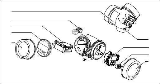
3.1.3Electronics housing
5 |
4 |
3 |
2 |
9 |
1 |
6 |
7 |
8 |
A0012422 |
3 Design of the electronics housing 1 Electronics compartment cover
2Display module
3Main electronics module
4Cable glands (1 or 2, depending on instrument version)
5Nameplate
6I/O electronics module
7 Terminals (pluggable spring terminals)
8 Connection compartment cover
9Grounding terminal
16 |
Endress+Hauser |

Micropilot FMR51, FMR52 HART |
Incoming acceptance and product identification |
|
|
4Incoming acceptance and product identification
4.1Incoming acceptance
Upon receipt of the goods check the following:
•Are the order codes on the delivery note and the product sticker identical?
•Are the goods undamaged?
•Do the nameplate data match the ordering information on the delivery note?
•Is the DVD with the operating tool present?
If required (see nameplate): Are the Safety Instructions (XA) present?
 If one of these conditions is not satisfied, contact your Endress+Hauser Sales Center.
4.2Product identification
The following options are available for identification of the measuring device:
•Nameplate specifications
•Extended order code with breakdown of the device features on the delivery note
•Enter serial numbers from nameplates in W@M Device Viewer
( www.endress.com/deviceviewer ): All information about the measuring device is displayed.
•Enter the serial number from the nameplates into the Endress+Hauser Operations App or scan the 2-D matrix code (QR code) on the nameplate with the Endress+Hauser Operations App: all the information for the measuring device is displayed.
For an overview of the scope of the associated Technical Documentation, refer to the following:
•The W@M Device Viewer: Enter the serial number from the nameplate (www.endress.com/deviceviewer)
•The Endress+Hauser Operations App: Enter the serial number from the nameplate or scan the 2-D matrix code (QR code) on the nameplate.
Endress+Hauser |
17 |

Incoming acceptance and product identification |
Micropilot FMR51, FMR52 HART |
|
|
4.2.1 |
Nameplate |
|
|
|
|
|
|
|
|
|
|
|
|
92 (3.62) |
|
|
|
|
|
|
|
2 |
|
|
|
|
|
|
1 |
|
|
|
|
|
|
|
Order code: |
|
3 |
|
|
|
10 |
|
|
Ser. no.: |
|
4 |
|
8 |
|
|
|
|
Ext. ord. cd.: |
5 |
|
|
|
|||
|
|
|
|
|
||||
|
|
|
|
|
|
|
|
|
|
|
|
|
26 |
|
|
|
|
|
|
|
|
25 |
|
|
|
(1.85) |
|
Tp max = |
|
24 |
MWP: |
6 |
9 |
||
|
|
|
23 |
LN = |
7 |
|
47 |
|
|
|
|
|
|
15 |
|
|
|
|
Ta: |
22 |
|
21 |
|
|
|
|
|
Mat.: |
|
|
|
|
|
|
|
|
|
|
|
20 |
|
|
11 |
|
|
FW: |
18 |
|
Dev.Rev.: |
16 |
|
|
|
|
|
|
|
|
||||
|
|
|
|
|
|
|
if modification |
|
|
19 |
|
|
17 |
|
13 X = see sep. label |
12 |
|
|
|
|
|
|
14 |
|||
|
|
|
|
|
|
Date: |
|
|
|
|
|
|
|
|
|
|
MM (IN) |
|
|
|
|
|
|
|
|
A0019444 |
4 Nameplate of the Micropilot
1Device name
2 Address of manufacturer
3Order code
4Serial number (Ser. no.)
5 Extended order code (Ext. ord. cd.)
6Process pressure
7 Antenna length (only for FMR51 with antenna extension)
8Certificate symbol
9 Certificate and approval relevant data
10Degree of protection: e.g. IP, NEMA
11Document number of the Safety Instructions: e.g. XA, ZD, ZE
12Data Matrix Code
13Modification mark
14Manufacturing date: year-month
15Temperature resistance of the cable
16Device revision
17Additional information about the device version (certificates, approvals, communication): e.g. SIL, PROFIBUS
18Firmware version (FW)
19CE mark, C-Tick
20Profibus PA: Profil-Version; FOUNDATION Fieldbus: Device ID
21Material in contact with process
22Permitted ambient temperature (Ta)
23Size of the thread of the cable glands
24Maximum process temperature
25Signal outputs
26Operating voltage
Only 33 digits of the extended order code can be indicated on the nameplate. If the extended order code exceeds 33 digits, the rest will not be shown. However, the complete extended order code can be viewed in the operating menu of the device:
Extended order code 1 to 3 parameter
18 |
Endress+Hauser |

Micropilot FMR51, FMR52 HART |
Storage, Transport |
|
|
5Storage, Transport
5.1Storage conditions
•Permitted storage temperature: –40 to +80 °C (–40 to +176 °F)
•Use the original packaging.
5.2Transport product to the measuring point
NOTICE
Housing or antenna horn may be damaged or break away.
Risk of injury!
Transport the measuring device to the measuring point in its original packaging or at the process connection.
Do not fasten lifting devices (hoisting slings, lifting eyes etc.) at the housing or the antenna horn but at the process connection. Take into account the mass center of the device in order to avoid unintended tilting.
Comply with the safety instructions, transport conditions for devices over 18kg (39.6lbs) (IEC61010).
A0016875
Endress+Hauser |
19 |

Installation |
Micropilot FMR51, FMR52 HART |
|
|
6Installation
6.1Installation conditions
6.1.1Mounting position
1 |
|
2 |
3 |
|
||||||||||||
|
|
|
|
|
|
|
|
|
|
|
|
|
|
|
|
|
|
|
|
|
|
|
|
|
|
|
|
|
|
|
|
|
|
|
|
|
|
|
|
|
|
|
|
|
|
|
|
|
|
|
|
|
|
|
|
|
|
|
|
|
|
|
|
|
|
|
|
A
A0016882
•Recommended distance A from wall to outer edge of nozzle: ~ 1/6 of tank diameter.
Nevertheless the device should not be installed closer than 15 cm (5.91 in) to the tank wall.
•Not in the center (2), as interference can cause signal loss.
•Not above the fill stream (3).
•It is recommended to us a weather protection cover (1) in order to protect the device from direct sun or rain.
20 |
Endress+Hauser |
Micropilot FMR51, FMR52 HART |
Installation |
|
|
6.1.2Vessel installations
Avoid any installations (point level switches, temperature sensors, braces, vacuum rings, heating coils, baffles etc.) inside the signal beam. Take into account the beam angle → 23.
A0018944
6.1.3Reduction of interference echoes
Metallic screens mounted at a slope spread the radar signal and can, therefore, reduce interference echoes.
A0016890
Endress+Hauser |
21 |

Installation |
Micropilot FMR51, FMR52 HART |
|
|
6.1.4Measurement in a plastic vessel
If the outer wall of the vessel is made of a non-conductive material (e.g. GRP), microwaves can also be reflected off interfering installations outside the vessel (e.g. metallic pipes (1), ladders (2), grates (3), ...). Therefore, there should be no such interfering installations in the signal beam. Please contact Endress+Hauser for further information.


 2
2
1 |
3 |
|
A0017123
6.1.5Optimization options
•Antenna size
The bigger the antenna, the smaller the beam angle α and the fewer interference echoes → 23.
•Mapping
The measurement can be optimized by means of electronic suppression of interference echoes.
See the Confirm distance parameter (→ 129) for details.
•Antenna alignment
Take into account the marker on the flange or threaded connection .
•Stilling well
A stilling well can be applied to avoid interferences → 30.
•Metallic screens mounted at a slope
They spread the radar signals and can, therefore, reduce interference echoes.
22 |
Endress+Hauser |

Micropilot FMR51, FMR52 HART |
Installation |
|
|
6.1.6Beam angle
α
W = 2 . D . TAN _2
D
α
W
A0016891
5 Relationship between beam angle α, distance D and beamwidth diameter W
The beam angle is defined as the angle α where the energy density of the radar waves reaches half the value of the maximum energy density (3-dB-width). Microwaves are also emitted outside the signal beam and can be reflected off interfering installations.
Beam diameter W as a function of beam angle α and measuring distance D:
FMR51
Antenna size |
40 mm (1½ in) |
50 mm (2 in) |
80 mm (3 in) |
100 mm (4 in) |
|
|
|
|
|
Beam angle α |
23° |
18° |
10° |
8° |
|
|
|
|
|
|
|
|
|
|
Measuring |
|
Beamwidth diameter W |
|
|
distance (D) |
|
|
|
|
|
|
|
|
|
3 m (9.8 ft) |
1.22 m (4 ft) |
0.95 m (3.1 ft) |
0.53 m (1.7 ft) |
0.42 m (1.4 ft) |
|
|
|
|
|
6 m (20 ft) |
2.44 m (8 ft) |
1.9 m (6.2 ft) |
1.05 m (3.4 ft) |
0.84 m (2.8 ft) |
|
|
|
|
|
9 m (30 ft) |
3.66 m (12 ft) |
2.85 m (9.4 ft) |
1.58 m (5.2 ft) |
1.26 m (4.1 ft) |
|
|
|
|
|
12 m (39 ft) |
4.88 m (16 ft) |
3.80 m (12 ft) |
2.1 m (6.9 ft) |
1.68 m (5.5 ft) |
|
|
|
|
|
15 m (49 ft) |
6.1 m (20 ft) |
4.75 m (16 ft) |
2.63 m (8.6 ft) |
2.10 m (6.9 ft) |
|
|
|
|
|
20 m (66 ft) |
8.14 m (27 ft) |
6.34 m (21 ft) |
3.50 m (11 ft) |
2.80 m (9.2 ft) |
|
|
|
|
|
25 m (82 ft) |
10.17 m (33 ft) |
7.92 m (26 ft) |
4.37 m (14 ft) |
3.50 m (11 ft) |
|
|
|
|
|
30 m (98 ft) |
- |
9.50 m (31 ft) |
5.25 m (17 ft) |
4.20 m (14 ft) |
|
|
|
|
|
35 m (115 ft) |
- |
11.09 m (36 ft) |
6.12 m (20 ft) |
4.89 m (16 ft) |
|
|
|
|
|
40 m (131 ft) |
- |
12.67 m (42 ft) |
7.00 m (23 ft) |
5.59 m (18 ft) |
|
|
|
|
|
45 m (148 ft) |
- |
- |
7.87 m (26 ft) |
6.29 m (21 ft) |
|
|
|
|
|
60 m (197 ft) |
- |
- |
10.50 m (34 ft) |
8.39 m (28 ft) |
|
|
|
|
|
70 m (230 ft) |
- |
- |
- |
9.79 m (32 ft) |
|
|
|
|
|
Endress+Hauser |
23 |

Installation |
|
Micropilot FMR51, FMR52 HART |
||
|
|
|
|
|
|
|
|
|
|
|
|
FMR52 |
|
|
|
|
|
|
|
|
Antenna size |
50 mm (2 in) |
|
80 mm (3 in) |
|
|
|
|
|
|
Beam angle α |
18° |
|
10° |
|
|
|
|
|
|
|
|
||
|
Measuring distance (D) |
Beamwidth diameter W |
||
|
|
|
|
|
|
3 m (9.8 ft) |
0.95 m (3.1 ft) |
|
0.53 m (1.7 ft) |
|
|
|
|
|
|
6 m (20 ft) |
1.9 m (6.2 ft) |
|
1.05 m (3.4 ft) |
|
|
|
|
|
|
9 m (30 ft) |
2.85 m (9.4 ft) |
|
1.58 m (5.2 ft) |
|
|
|
|
|
|
12 m (39 ft) |
3.80 m (12 ft) |
|
2.1 m (6.9 ft) |
|
|
|
|
|
|
15 m (49 ft) |
4.75 m (16 ft) |
|
2.63 m (8.6 ft) |
|
|
|
|
|
|
20 m (66 ft) |
6.34 m (21 ft) |
|
3.50 m (11 ft) |
|
|
|
|
|
|
25 m (82 ft) |
7.92 m (26 ft) |
|
4.37 m (14 ft) |
|
|
|
|
|
|
30 m (98 ft) |
9.50 m (31 ft) |
|
5.25 m (17 ft) |
|
|
|
|
|
|
35 m (115 ft) |
11.09 m (36 ft) |
|
6.12 m (20 ft) |
|
|
|
|
|
|
40 m (131 ft) |
12.67 m (42 ft) |
|
7.00 m (23 ft) |
|
|
|
|
|
|
45 m (148 ft) |
- |
|
7.87 m (26 ft) |
|
|
|
|
|
|
60 m (197 ft) |
- |
|
10.50 m (34 ft) |
|
|
|
|
|
6.2Measuring conditions
•In case of boiling surfaces, bubbling or tendency for foaming use FMR53 or FMR54. Depending on its consistence, foam can either absorb microwaves or reflect them off the foam surface. Measurement is possible under certain conditions. For FMR50, FMR51 and FMR52, the additional option "Advanced dynamics" is recommended in these cases (feature 540: "Application Package", option EM).
•In case of heavy steam development or condensate, the maximum measuring range of FMR50, FMR51 and FMR52 may decrease depending on density, temperature and composition of the steam → use FMR53 or FMR54.
•For the measurement of absorbing gases such as ammonia NH3 or some fluorocarbons 2), please use Levelflex or Micropilot FMR54 in a stilling well.
•The measuring range begins, where the beam hits the tank bottom. Particularly with dish bottoms or conical outlets the level cannot be detected below this point.
•In stilling well applications, the electromagnetic waves do not propagate completely outside the tube. It must be taken into account that the accuracy may be reduced in the area C. In order to guarantee the required accuracy in these cases, it is recommended to position the zero-point at a distance C above the end of the tube (see figure).
•In case of media with a low dielectric constant (εr = 1.5 to 4) 3) the tank bottom can be visible through the medium at low levels (low height C). Reduced accuracy has to be expected in this range. If this is not acceptable, we recommend positioning the zero point at a distance C (see figure) above the tank bottom in these applications.
•In principle it is possible to measure up to the tip of the antenna with FMR51, FMR53 and FMR54. However, due to considerations regarding corrosion and build-up, the end of the measuring range should not be chosen any closer than A (see figure) to the tip of the antenna.
•When using FMR54 with planar antenna, especially for media with low dielectric constants, the end of the measuring range should not be closer than A: 1 m (3.28 ft) to the flange.
•The smallest possible measuring range B depends on the antenna version (see figure).
•The tank height should be at least H (see table).
2)Affected compounds are e.g. R134a, R227, Dymel 152a.
3)Dielectric constants of important media commonly used in various industries are summarized in the DC manual (CP01076F) and in the Endress +Hauser "DC Values App" (available for Android and iOS).
24 |
Endress+Hauser |

Micropilot FMR51, FMR52 HART |
|
Installation |
|
|
|
|
|
|
|
|
|
|
|
|
|
|
|
|
|
|
|
|
|
|
|
|
|
|
|
|
|
A
100%
B |
H |
0% |
C |
|
|
|
ØD |
|
A0018872 |
Device |
A [mm (in)] |
B [m (ft)] |
C [mm (in)] |
|
H [m (ft)] |
|
|
|
|
|
|
|
|
FMR51 |
50(1.97) |
> 0.2 (0.7) |
50 to 250 (1.97 to |
9.84) |
> 0.3 (1.0) |
|
|
|
|||||
FMR52 |
200(7.87) |
|||||
|
|
|
|
|||
|
|
|
|
|
|
6.3 Mounting cladded flanges
• Use flange screws according to the number of flange holes.
• Tighten the screws with the required torque (see table).
• Retighten the screws after 24 hours or after the first temperature cycle.
• Depending on process pressure and process temperature check and retighten the screws at regular intervals.
Usually, the PTFE flange cladding also serves as a seal between the nozzle and the device flange.
Flange size |
Number of screws |
Recommended torque [Nm] |
|
|
|
|
|
|
|
minimum |
maximum |
|
|
|
|
EN |
|
|
|
|
|
|
|
DN50/PN16 |
4 |
45 |
65 |
|
|
|
|
DN80/PN16 |
8 |
40 |
55 |
|
|
|
|
DN100/PN16 |
8 |
40 |
60 |
|
|
|
|
DN150/PN16 |
8 |
75 |
115 |
|
|
|
|
ASME |
|
|
|
|
|
|
|
2"/150lbs |
4 |
40 |
55 |
|
|
|
|
3"/150lbs |
4 |
65 |
95 |
|
|
|
|
4"/150lbs |
8 |
45 |
70 |
|
|
|
|
6"/150lbs |
8 |
85 |
125 |
|
|
|
|
Endress+Hauser |
25 |

Installation |
|
|
Micropilot FMR51, FMR52 HART |
|
Flange size |
Number of screws |
Recommended torque [Nm] |
||
|
|
|
minimum |
maximum |
JIS |
|
|
|
|
10K |
50A |
4 |
40 |
60 |
10K |
80A |
8 |
25 |
35 |
10K |
100A |
8 |
35 |
55 |
10K |
100A |
8 |
75 |
115 |
6.4Installation in vessel (free space)
6.4.1Horn antenna (FMR51)
Alignment
•Align the antenna vertically to the product surface.
The maximum range may be reduced if the horn antenna is not vertically aligned.
•A marking at the flange (somewhere between the flange holes) or the boss enables alignment of the antenna. This marking must be aligned towards the tank wall as well as possible.
A |
|
B |
|
90° |
90° |
90° |
90° |
|
|
||
90° |
|
90° |
|
|
|
||
90° |
|
90° |
|
|
90° |
|
90° |
|
|
|
A0018974 |
Depending on the device version the marking may be a circle or two short parallel lines.
Nozzle mounting
For optimum measurement, the tip of the antenna should extend below the nozzle.
Depending on the antenna size this is achieved by the following maximum nozzle heights:
26 |
Endress+Hauser |

Micropilot FMR51, FMR52 HART |
|
|
|
|
|
|
|
|
Installation |
|||
|
|
|
|
|
|
|
|
|
|
|
|
|
|
|
|
|
|
|
|
|
|
|
|
|
|
|
|
|
|
|
|
|
|
|
|
|
|
|
|
|
|
|
|
|
|
|
|
|
|
|
|
|
|
|
|
|
|
|
|
|
|
|
|
|
|
|
|
|
|
|
|
|
|
|
|
|
|
MAX
H
|
|
A0016820 |
6 |
Nozzle height for horn antenna (FMR51) |
|
|
|
|
Antenna 1) |
Maximum nozzle height Hmax |
|
BA: Horn 40mm/1-1/2" |
86 mm (3.39 in) |
|
|
|
|
BB: Horn 50mm/2" |
115 mm (4.53 in) |
|
|
|
|
BC: Horn 80mm/3" |
211 mm (8.31 in) |
|
|
|
|
BD Horn 100mm/4" |
282 mm (11.1 in) |
|
|
|
|
1)Feature 070 of the product structure
Conditions for longer nozzles
If the medium has good reflective properties, higher nozzles can be accepted. In this case the maximum nozzle height, Hmax, is dependent on the nozzle diameter, D:
MAX
H
ØD
A0023611
Nozzle diameter D |
Maximum nozzle height |
Recommended antenna 1) |
|
Hmax |
|
40 mm (1.5 in) |
100 mm (3.9 in) |
BA: Horn 40mm/1-1/2" |
|
|
|
50 mm (2 in) |
150 mm (5.9 in) |
BB: Horn 50mm/2" |
|
|
|
80 mm (3 in) |
250 mm (9.8 in) |
BC: Horn 80mm/3" |
|
|
|
Endress+Hauser |
27 |

Installation |
|
Micropilot FMR51, FMR52 HART |
|
|
|
|
|
|
|
|
|
|
Nozzle diameter D |
Maximum nozzle height |
Recommended antenna 1) |
|
|
Hmax |
|
|
100 mm (4 in) |
500 mm (19.7 in) |
BD: Horn 100mm/4" |
|
|
|
|
|
150 mm (6 in) |
800 mm (31.5 in) |
BD: Horn 100mm/4" |
|
|
|
|
1)Feature 070 of the product structure
If the antenna doesn't extend below the nozzle, observe the following:
•The nozzle end must be smooth and free of burrs. If possible its edge should be rounded.
•An interference echo suppression must be performed.
•Please contact Endress+Hauser for applications with higher nozzles than those indicated in the table.
• For mounting in heigh nozzles the device is available in a version with an antenna extension of up to 1 000 mm (39.4 in) 4)
•The antenna extension may cause interference echoes in the near range. In this case it may occur that the maximum measurable level is reduced.
Threaded connection
For devices with a threaded connection it may be necessary - depending on the antenna size - to unmount the horn before fastening the device and to mount it again afterwards.
•Tighten with the hexagonal nut only.
•Tool : 55 mm hexagonal wrench
•Maximum permissible torque: 60 Nm (44 lbf ft)
6.4.2Measurement from the outside through plastic walls (FMR50/ FMR51)
•Dielectric constant of the medium: εr > 10
•If possible, use an antenna 100 mm (4 in).
•The distance from the lower edge of the antenna to the tank ceiling should be about 100 mm (4 in).
•If possible, avoid mounting locations where condensation or build-up might occur.
•In case of outdoor mounting, the space between antenna and vessel has to be protected from the elements.
•Do not mount any potential reflectors (e.g. pipes) outside the tank in the signal beam.
Suitable thickness of the tank ceiling:
Penetrated material |
PE |
PTFE |
PP |
Perspex |
|
|
|
|
|
DK / εr |
2.3 |
2.1 |
2.3 |
3.1 |
Optimum thickness 1) |
3.8 mm (0.15 in) |
4.0 mm (0.16 in) |
3.8 mm (0.15 in) |
3.3 mm (0.13 in) |
1)Other possible values for the thickness are multiples of the values listed (e.g. for PE: 7,6 mm (0.3 in), 11,4 mm (0.45 in)
4)Feature 610 "Accessory mounted" of the product structure.
28 |
Endress+Hauser |
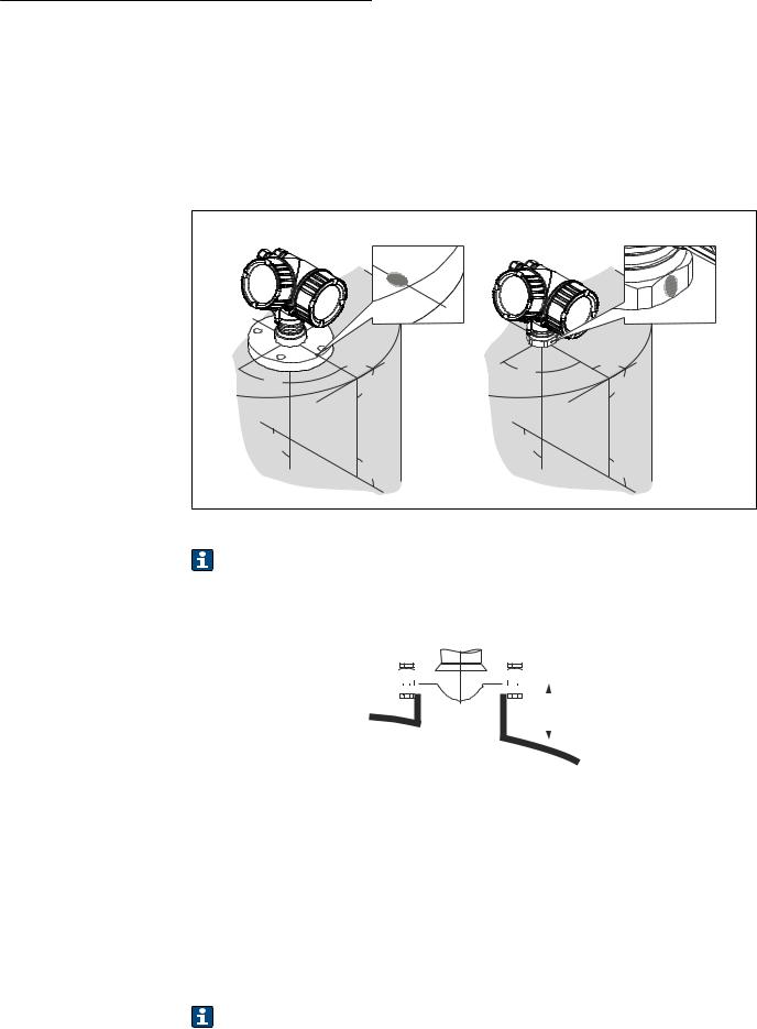
Micropilot FMR51, FMR52 HART |
Installation |
6.4.3Horn antenna, flush mount (FMR52)
Alignment
•Align the antenna vertically to the product surface.
The maximum range may be reduced if the horn antenna is not vertically aligned.
•A marking at the flange (somwhere between the flange holes) or the boss enables alignment of the antenna. This marking must be aligned towards the tank wall as well as possible.
A |
|
B |
|
90° |
90° |
90° |
90° |
|
|
||
90° |
|
90° |
|
|
|
||
90° |
|
90° |
|
|
90° |
|
90° |
|
|
|
A0018974 |
Depending on the device version the marking may be a circle or two short parallel lines.
Nozzle mounting
|
|
|
|
|
|
|
|
|
|
|
|
|
|
|
|
|
|
|
|
|
|
|
|
|
|
|
|
|
|
|
|
|
|
|
|
|
|
|
|
|
|
|
|
|
MAX |
|
|
|
|
|
|
|
|
|
|
|
|
|
|
|
|
|
|
|
|
|
|
|
|
||
|
|
|
|
|
|
|
|
H |
|
||
|
|
|
|
|
|
|
|
|
|
|
|
|
|
|
|
|
|
|
|
|
|
|
|
|
|
|
|
|
|
|
|
|
|
|
|
|
|
|
|
|
|
|
|
|
|
|
A0016819 |
7 |
Nozzle height for horn antenna, flush mount (FMR52) |
||||||||||
|
|
|
|||||||||
Antenna 1) |
|
Maximum nozzle height Hmax |
|||||||||
BO: Horn 50mm/2" |
|
500 mm (19.7 in) |
|||||||||
|
|
|
|||||||||
BP: Horn 80mm/3" |
|
500 mm (19.7 in) |
|||||||||
|
|
|
|
|
|
|
|
|
|
|
|
1)Feature 070 of the product structure
 Please contact Endress+Hauser for applications with higher nozzle.
•For flanges with PTFE cladding: Observe the notes on the mounting of cladded flanges → 25.
•Usually, the PTFE flange cladding also serves as a seal between the nozzle and the device flange.
Endress+Hauser |
29 |

Installation |
Micropilot FMR51, FMR52 HART |
|
|
6.5Installation in stilling well
90°
1
A0016841
8 Installation in stilling well
1Marking for antenna alignment
•For horn antenna: Align the marking towards the slots of the stilling well.
•Measurements can be performed through an open full bore ball valve without any problems.
•After mounting, the housing can be turned 350° in order to facilitate access to the display and the terminal compartment → 34.
6.5.1Recommendations for the stilling well
•Metal (no enamel coating; plastic on request).
•Constant diameter.
•Diameter of stilling well not larger than antenna diameter.
•Diameter difference between horn antenna and inner diameter of the stilling well as small as possible.
•Weld seam as smooth as possible and on the same axis as the slots.
•Slots offset 180° (not 90°).
•Slot width or diameter of holes max. 1/10 of pipe diameter, de-burred. Length and number do not have any influence on the measurement.
•Select horn antenna as big as possible. For intermedaite sizes (e.g. 180 mm (7 in)) select next larger antenna and adapt it mechanically (for horn antennas)
•At any transition (i.e. when using a ball valve or mending pipe segments), no gap may be left exceeding 1 mm (0.04 in).
•The stilling well must be smooth on the inside (average roughness Rz ≤
6.3 μm (248 μin)). Use extruded or parallel welded metal pipe. An extension of the pipe is possible with welded flanges or pipe sleeves. Flange and pipe have to be properly aligned at the inside.
•Do not weld through the pipe wall. The inside of the stilling well must remain smooth. In case of unintentional welding through the pipe, the weld seam and any unevenness on the inside need to be carefully removed and smoothened. Otherwise, strong interference echoes will be generated and material build-up will be promoted.
•In the case of smaller nominal widths flanges must be welded to the pipe such that they
allow for a correct orientation (marker aligned toward slots).
30 |
Endress+Hauser |
Loading...