


 Loading...
BA00332P/00/EN/19.16
71336242
valid from Software version: 02.30.zz
Products |
Solutions |
Services |
|
|
|
Operating Instructions
Deltapilot S FMB70
Hydrostatic level measurement
Deltapilot S FMB70 with 4...20 mA HART
|
Order code: |
XXXXX-XXXXXX |
1. |
Ser. no.: |
XXXXXXXXXXXX |
|
|
|
|
|
|
|
|
|
|
|
|
|
|
|
|
|
|
|
|
|
|
|
|
|
|
|
|
|
|
|
|
|
|
|
|
|
|
|
|
|
|
|
|
|
|
|
|
|
|
|
|
|
|
|
|
|
|
|
|
|
|
|
|
|
|
|
|
|
|
|
|
|
|
|
|
|
|
|
|
|
|
|
|
|
|
|
|
|
|
|
|
|
|
|
|
|
|
|
|
|
|
|
|
|
|
|
|
|
|
|
|
|
|
|
|
|
|
|
|
|
|
|
|
|
|
|
|
|
|
|
|
|
|
|
|
|
|
|
|
|
|
|
|
|
|
|
|
|
|
|
|
|
|
|
|
|
|
|
|
|
|
|
|
|
|
|
|
|
|
|
|
|
|
|
|
|
|
|
|
|
|
|
|
|
|
|
|
|
|
|
|
|
|
|
|
|
|
|
|
|
|
|
|
|
|
|
|
|
|
|
|
Serial number |
|
|
|
|
|
|
|
|
|
|
|
|
|
|
|
|
|
|
|
||
|
|
|
|
|
|
|
|
|
|
|
|
|
|
|
|
|
|
|
|
|
|
|
|||
|
|
|
|
|
|
|
|
|
|
|
|
|
|
|
|
|
|
||||||||
|
|
|
|
|
|
|
|
|
|
|
|
|
|
|
|
|
|
|
|
|
|
|
|
|
|
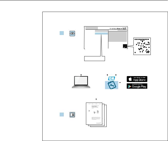
2. |
www.endress.com/deviceviewer |
|
|
|
|
|
|
|
|
|
|
Endress+Hauser |
|||||||||||||
|
|
|
|
|
|
|
|
|
|
|
|
|
|
|
|
|
|
Operations App |
|||||||
|
|
|
|
|
|
|
|
|
|
|
|
|
|
|
|
|
|
|
|
|
|
|
|
|
|
|
|
|
|
|
|
|
|
|
|
|
|
|
|
|
|
|
|
|
|
|
|
|
|
|
|
|
|
|
|
|
|
|
|
|
|
|
|
|
|
|
|
|
|
|
|
|
|
|
|
|
|
|
|
|
|
|
|
|
|
|
|
|
|
|
|
|
|
|
|
|
|
|
|
|
|
|
|
|
|
|
|
|
|
|
|
|
|
|
|
|
|
|
|
|
|
|
|
|
|
|
|
|
|
|
|
|
|
|
|
|
|
|
|
|
|
|
|
|
|
|
|
|
|
|
|
|
|
|
|
3.
A0023555
Make sure the document is stored in a safe place such that it is always available when working on or with the device.
To avoid danger to individuals or the facility, read the "Basic safety instructions" section carefully, as well as all other safety instructions in the document that are specific to working procedures.
The manufacturer reserves the right to modify technical data without prior notice. Your Endress+Hauser Sales Center will supply you with current information and updates to these Instructions.
2 |
Endress+Hauser |

Deltapilot S FMB70 with 4...20 mA HART
Table of contents
1 |
Document information . . . . . . . . . . . . . |
. 4 |
1.1 |
Document function . . . . . . . . . . . . . . . . . . . . . . . . . |
. 4 |
1.2 |
Symbols used . . . . . . . . . . . . . . . . . . . . . . . . . . . . . . |
. 4 |
1.3 |
Registered trademarks . . . . . . . . . . . . . . . . . . . . . . |
. 5 |
1.4 |
Terms and abbreviations . . . . . . . . . . . . . . . . . . . . |
. 6 |
1.5 |
Turn down calculation . . . . . . . . . . . . . . . . . . . . . . |
. 7 |
2 |
Basic safety instructions . . . . . . . . . . . . |
. 8 |
2.1 |
Requirements concerning the staff . . . . . . . . . . . . |
. 8 |
2.2 |
Designated use . . . . . . . . . . . . . . . . . . . . . . . . . . . . |
. 8 |
2.3 |
Workplace safety . . . . . . . . . . . . . . . . . . . . . . . . . . |
. 8 |
2.4 |
Operational safety . . . . . . . . . . . . . . . . . . . . . . . . . . |
. 8 |
2.5 |
Hazardous area . . . . . . . . . . . . . . . . . . . . . . . . . . . . |
. 9 |
2.6 |
Product safety . . . . . . . . . . . . . . . . . . . . . . . . . . . . . |
. 9 |
2.7 |
Functional Safety SIL3 (optional) . . . . . . . . . . . . . |
. 9 |
3 |
Identification . . . . . . . . . . . . . . . . . . . . . |
10 |
3.1 |
Product identification . . . . . . . . . . . . . . . . . . . . . . |
10 |
3.2 |
Device designation . . . . . . . . . . . . . . . . . . . . . . . . |
10 |
3.3 |
Scope of delivery . . . . . . . . . . . . . . . . . . . . . . . . . . |
12 |
3.4 |
CE mark, declaration of conformity . . . . . . . . . . |
12 |
4 |
Installation . . . . . . . . . . . . . . . . . . . . . . . |
13 |
4.1 |
Incoming acceptance and storage . . . . . . . . . . . . |
13 |
4.2 |
Installation conditions . . . . . . . . . . . . . . . . . . . . . |
13 |
4.3 |
General installation instructions . . . . . . . . . . . . . |
13 |
4.4 |
Installation instructions . . . . . . . . . . . . . . . . . . . . |
14 |
4.5 |
Post-installation check . . . . . . . . . . . . . . . . . . . . . |
19 |
5 |
Wiring . . . . . . . . . . . . . . . . . . . . . . . . . . . |
20 |
5.1 |
Connecting the device . . . . . . . . . . . . . . . . . . . . . |
20 |
5.2 |
Connecting the measuring unit . . . . . . . . . . . . . . |
22 |
5.3 |
Potential matching . . . . . . . . . . . . . . . . . . . . . . . . |
24 |
5.4 |
Overvoltage protection (optional) . . . . . . . . . . . . |
24 |
5.5 |
Post-connection check . . . . . . . . . . . . . . . . . . . . . |
24 |
6 |
Operation. . . . . . . . . . . . . . . . . . . . . . . . . |
25 |
6.1 |
On-site display (optional) . . . . . . . . . . . . . . . . . . |
25 |
6.2 |
Operating elements . . . . . . . . . . . . . . . . . . . . . . . |
26 |
6.3On-site operation –
on-site display not connected . . . . . . . . . . . . . . . 28
6.4On-site operation –
on-site display connected . . . . . . . . . . . . . . . . . . . 31 6.5 HistoROM®/M-DAT (optional) . . . . . . . . . . . . . . 33 6.6 Operation via SFX100 . . . . . . . . . . . . . . . . . . . . . . 36 6.7 Endress+Hauser operating program . . . . . . . . . . 36 6.8 Locking/unlocking operation . . . . . . . . . . . . . . . 36 6.9 Factory setting (reset) . . . . . . . . . . . . . . . . . . . . . 37
7 Commissioning. . . . . . . . . . . . . . . . . . . . 39
7.1 Configuring messages . . . . . . . . . . . . . . . . . . . . . 39 7.2 Function check . . . . . . . . . . . . . . . . . . . . . . . . . . . 39
7.3 Selecting language and measuring mode . . . . . . 39 7.4 Position adjustment . . . . . . . . . . . . . . . . . . . . . . . . 40 7.5 Level measurement . . . . . . . . . . . . . . . . . . . . . . . . 42 7.6 Pressure measurement . . . . . . . . . . . . . . . . . . . . . 46
8 Maintenance . . . . . . . . . . . . . . . . . . . . . 47
8.1 Exterior cleaning . . . . . . . . . . . . . . . . . . . . . . . . . . . 47
9 Trouble-shooting . . . . . . . . . . . . . . . . . 48
9.1 Messages . . . . . . . . . . . . . . . . . . . . . . . . . . . . . . . . . 48 9.2 Response of outputs to errors . . . . . . . . . . . . . . . . 56 9.3 Confirming messages . . . . . . . . . . . . . . . . . . . . . . . 58 9.4 Repair . . . . . . . . . . . . . . . . . . . . . . . . . . . . . . . . . . . . 59 9.5 Repair of Ex-certified devices . . . . . . . . . . . . . . . . 59 9.6 Spare Parts . . . . . . . . . . . . . . . . . . . . . . . . . . . . . . . . 59 9.7 Return . . . . . . . . . . . . . . . . . . . . . . . . . . . . . . . . . . . 59 9.8 Disposal . . . . . . . . . . . . . . . . . . . . . . . . . . . . . . . . . . 59 9.9 Software history . . . . . . . . . . . . . . . . . . . . . . . . . . . 60
10 Technical data . . . . . . . . . . . . . . . . . . . . 60
Index . . . . . . . . . . . . . . . . . . . . . . . . . . . . 61
Endress+Hauser |
3 |

Document information |
Deltapilot S FMB70 with 4...20 mA HART |
|
|
1 Document information
1.1Document function
These Operating Instructions contain all the information that is required in various phases of the life cycle of the device: from product identification, incoming acceptance and storage, to mounting, connection, operation and commissioning through to troubleshooting, maintenance and disposal.
1.2Symbols used
1.2.1Safety symbols
Symbol Meaning
DANGER!
DANGER This symbol alerts you to a dangerous situation. Failure to avoid this situation will result in
A0011189-DE seriousor fatal injury.
WARNING!
WARNING This symbol alerts you to a dangerous situation. Failure to avoid this situation can result in
A0011190-DE seriousor fatal injury.
CAUTION!
CAUTION This symbol alerts you to a dangerous situation. Failure to avoid this situation can result in
A0011191-DE minoror medium injury.
NOTICE!
NOTICE This symbol contains information on procedures and other facts which do not result in
A0011192-DE personalinjury.
1.2.2Electrical symbols
Symbol |
Meaning |
Symbol |
Meaning |
||
|
|
|
|
|
|
|
|
|
Direct current |
|
Alternating current |
|
|
|
|
|
|
|
|
|
Direct current and alternating current |
|
Ground connection |
|
|
|
|
) |
A grounded terminal which, as far as |
|
|
|
|
|
the operator is concerned, is grounded |
|
|
|
|
|
via a grounding system. |
|
|
|
|
|
|
|
|
|
Protective ground connection |
|
Equipotential connection |
|
|
|
A terminal which must be connected |
|
A connection that has to be connected |
|
|
|
to ground prior to establishing any |
|
to the plant grounding system: This |
|
|
|
other connections. |
|
may be a potential equalization line or |
|
|
|
|
|
a star grounding system depending on |
|
|
|
|
|
national or company codes of practice. |
|
|
|
|
|
|
1.2.3Tool symbols
Symbol |
Meaning |
|
Allen key |
A0011221
Hexagon wrench
A0011222
4 |
Endress+Hauser |
Deltapilot S FMB70 with 4...20 mA HART |
Document information |
|
|
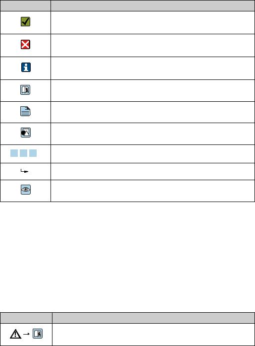
1.2.4Symbols for certain types of information
Symbol Meaning
Permitted
Indicates procedures, processes or actions that are permitted.
A0011182
Forbidden
Indicates procedures, processes or actions that are forbidden.
A0011184
Tip
Indicates additional information.
A0011193
Reference to documentation
A0028658
Reference to page
A
A0028659
Reference to graphic
A0028660
Series of steps
1. , 2. , 3. …
A0031595
Result of a sequence of actions
A0018343
Visual inspection
A0028673
1.2.5Symbols in graphics
|
Symbol |
Meaning |
|||||
|
|
|
|
|
|
|
|
1, 2, 3, 4, ... |
Item numbers |
||||||
|
|
|
|
|
|
|
|
|
|
|
|
|
|
|
Series of steps |
|
1. |
, |
2. |
, |
3. |
… |
|
|
|
||||||
|
|
|
|
|
|
A0031595 |
|
|
|
|
|
|
|
|
|
|
A, B, C, D, ... |
Views |
|||||
|
|
|
|
|
|
|
|
1.2.6Symbols at the device
Symbol Meaning
Safety instructions
Observe the safety instructions contained in the associated Operating Instructions.
A0019159
1.3Registered trademarks
KALREZ, VITON, TEFLON
Registered trademarks of E.I. Du Pont de Nemours & Co., Wilmington, USA
TRI-CLAMP
Registered trademark of Ladish & Co., Inc., Kenosha, USA
HART
Registered trademark of the HART Communication Foundation, Austin, USA.
GORE-TEX®
Registered trademarks of W.L. Gore & Associates, Inc., USA
Endress+Hauser |
5 |

Document information |
Deltapilot S FMB70 with 4...20 mA HART |
|
|
1.4Terms and abbreviations
|
|
|
1 |
|
|
|
|
|
2 |
|
|
|
|
3 |
|
|
|
|
|
4 |
|
|
|
|
|
|
|
|
p |
|
0 |
|
|
|
|
LRL |
LRV |
URV |
URL |
MWP |
OPL |
A0029505
Position |
Term/Abbreviation |
Explanation |
|
|
|
1 |
OPL |
The OPL (over pressure limit = sensor overload limit) for the sensors |
|
|
depends on the lowest-rated element, with regard to pressure, of the |
|
|
selected components, i.e. the process connection must be taken into |
|
|
consideration in addition to the measuring cell. Also observe pressure- |
|
|
temperature dependency. For the relevant standards and additional notes, |
|
|
see technical information. |
|
|
The OPL may be applied for a limited time period. |
|
|
|
2 |
MWP |
The MWP (maximum working pressure) for the sensors depends on the |
|
|
lowest-rated element, with regard to pressure, of the selected components, |
|
|
i.e. the process connection has to be taken into consideration in addition to |
|
|
the measuring cell. Also observe pressure-temperature dependency. For the |
|
|
relevant standards and additional notes, see technical information. |
|
|
The MWP may be applied for an unlimited time. |
|
|
|
3 |
Maximum sensor |
Range between LRL and URL |
|
measuring range |
This span is the maximum calibratable/adjustable measuring span. |
|
|
|
4 |
Calibrated/Adjusted |
Range between LRV and URV |
|
measuring span |
Factory setting: 0...URL |
|
|
Other calibrated spans can be ordered with customised settings. |
|
|
|
p |
- |
Pressure |
|
|
|
- |
LRL |
Lower range limit |
|
|
|
- |
URL |
Upper range limit |
|
|
|
- |
LRV |
Lower range value |
|
|
|
- |
URV |
Upper range value |
|
|
|
- |
TD |
Turn down |
|
|
|
6 |
Endress+Hauser |
Deltapilot S FMB70 with 4...20 mA HART |
Document information |
|
|
1.5Turn down calculation
|
|
|
1 = 2 |
|
3 |
|
LRL LRV |
URV |
URL |
||||
|
|
|
|
|
|
|
|
|
|
|
|
|
|
|
|
|
|
|
|
|
A0029545
Fig. 1:
1Calibrated/Adjusted measuring span
2Zero-based span
3Upper range limit
Example
• Sensor: 10 bar (150 psi) |
|
|
• Calibrated/Adjusted measuring span: 0...5 bar |
||
• Upper range limit (URL) = 10 bar (150 psi) |
(0...75 psi) |
||||
|
|
|
|
|
• Lower range value (LRV) = 0 bar |
Turn down (TD): |
|
|
• Upper range value (URV) = 5 bar (75 psi) |
||
|
|
|
|||
TD |
= |
|
URL |
|
|
|
|
|
|
||
|URV |
- |
LRV| |
|
||
|
|
|
|||
TD |
= |
10 bar (150 psi) |
= 2 |
||
|
|
|
|||
|5 bar (75 psi) |
- |
0 bar (0 psi)| |
|||
In this example, the TD is thus 2:1.
This span is based on the zero point.
Endress+Hauser |
7 |
Basic safety instructions |
Deltapilot S FMB70 with 4...20 mA HART |
|
|
2 Basic safety instructions
2.1Requirements concerning the staff
The personnel for installation, commissioning, diagnostics and maintenance must fulfill the following requirements:
•Trained, qualified specialists: must have a relevant qualification for this specific function and task
•Are authorized by the plant owner/operator
•Are familiar with federal/national regulations
•Before beginning work, the specialist staff must have read and understood the instructions in the Operating Instructions and supplementary documentation as well as in the certificates (depending on the application)
•Following instructions and basic conditions
The operating personnel must fulfill the following requirements:
•Being instructed and authorized according to the requirements of the task by the facility's owner-operator
•Following the instructions in these Operating Instructions
2.2Designated use
The Deltapilot S is a hydrostatic pressure transmitter for measuring level and pressure.
2.2.1Incorrect use
The manufacturer is not liable for damage caused by improper or non-designated use. Verification for borderline cases:
For special fluids and fluids for cleaning, Endress+Hauser is glad to provide assistance in verifying the corrosion resistance of fluid-wetted materials, but does not accept any warranty or liability.
2.3Workplace safety
For work on and with the device:
•Wear the required personal protective equipment according to federal/national regulations.
•Switch off the supply voltage before connecting the device.
2.4Operational safety
Risk of injury!
Operate the device in proper technical condition and fail-safe condition only.
The operator is responsible for interference-free operation of the device.
Conversions to the device
Unauthorized modifications to the device are not permitted and can lead to unforeseeable dangers:
If, despite this, modifications are required, consult with Endress+Hauser.
Repair
To ensure continued operational safety and reliability,
Carry out repairs on the device only if they are expressly permitted.
Observe federal/national regulations pertaining to repair of an electrical device.
Use original spare parts and accessories from Endress+Hauser only.
8 |
Endress+Hauser |
Deltapilot S FMB70 with 4...20 mA HART |
Basic safety instructions |
|
|
2.5Hazardous area
To eliminate a danger for persons or for the facility when the device is used in the hazardous area (e.g. explosion protection, pressure vessel safety):
•Based on the nameplate, check whether the ordered device is permitted for the intended use in the hazardous area.
•Observe the specifications in the separate supplementary documentation that is an integral part of these Instructions.
2.6Product safety
This measuring device is designed in accordance with good engineering practice to meet state-of-the- art safety requirements, has been tested, and left the factory in a condition in which they are safe to operate. It fulfills general safety requirements and legal requirements. It also conforms to the EC directives listed in the device-specific EC declaration of conformity. Endress+Hauser confirms this fact by applying the CE mark.
2.7Functional Safety SIL3 (optional)
If using devices for applications with safety integrity, the Functional Safety Manual must be observed thoroughly.
Endress+Hauser |
9 |

Identification |
Deltapilot S FMB70 with 4...20 mA HART |
|
|
3 Identification
3.1Product identification
The following options are available for identification of the measuring device:
•Nameplate specifications
•Order code with breakdown of the device features on the delivery note
•Enter serial numbers from nameplates in W@M Device Viewer (www.endress.com/deviceviewer) : All information about the measuring device is displayed.
For an overview of the technical documentation provided, enter the serial number from the nameplates in the W@M Device Viewer (www.endress.com/deviceviewer).
3.1.1Manufacturer address
Endress+Hauser GmbH+Co. KG Hauptstraße 1
79689 Maulburg, Germany
Address of the manufacturing plant: See nameplate.
3.2Device designation
3.2.1Nameplate
•The MWP (maximum working pressure) is specified on the nameplate. This value refers to a reference temperature of +20 °C (68°F) and may be applied to the device for an unlimited time. Observe temperature dependency of the MWP. The pressure values permitted at higher temperatures can be found in the standards EN 1092-1: 2001 Tab. 18 (With regard to their stability-temperature property, the materials 1.4435 and 1.4404 are grouped together under 13EO in EN 1092-1 Tab. 18. The chemical composition of the two materials can be identical.), ASME B 16.5a – 1998 Tab. 2-2.2 F316, ASME B 16.5a – 1998 Tab. 2.3.8 N10276, JIS B 2220.
•The test pressure corresponds to the over pressure limit (OPL) of the device = MWP x 1.5.
•The Pressure Equipment Directive (2014/68/EU) uses the abbreviation "PS".
The abbreviation "PS" corresponds to the MWP (maximum working pressure) of the measuring device.
Aluminum housing (T14/T15)
1
2
3
4
|
Order code: |
Ser. no.: |
|||||
|
|
Ext. order code: |
|
|
|
||
|
|
|
|
|
|
|
|
|
|
|
|
|
|
|
|
|
|
|
|
|
|
|
|
5
6
A0016056
Fig. 2: |
Nameplate |
1Device name
2Order code (for re-orders)
3Extended order code (complete)
4Technical data
5Serial number (for identification)
6Address of manufacturer
10 |
Endress+Hauser |
Deltapilot S FMB70 with 4...20 mA HART |
Identification |
|
|
Devices for use in hazardous areas are fitted with an additional nameplate.
1
2
A0021222
Fig. 3: Additional nameplate
1Approval-specific information
2Document number for safety instructions or drawing number
Hygenic stainless steel housing (T17)
1
2
3
4
5
6
Order code:
Ext. ord. cd.:
Ser. no.:
7
A0021552
Fig. 4: |
Nameplate |
1Device name
2Address of manufacturer
3Order code (for re-orders)
4Extended order code (complete)
5Serial number (for identification)
6Technical data
7Approval-specific information and document number for safety instructions or drawing number
3.2.2Identifying the sensor type
See parameter "Sensor Meas.Type" in Operating Instruction BA00274P.
Endress+Hauser |
11 |
Identification |
Deltapilot S FMB70 with 4...20 mA HART |
|
|
3.3Scope of delivery
The scope of delivery comprises:
•Deltapilot S hydrostatic pressure transmitter
•For devices with the "HistoROM/M-DAT" option: CD-ROMs with Endress+Hauser operating program
•Optional accessories
Documentation supplied:
•The Operating Instructions BA00332P and BA00274P are available via the Internet.See: www.endress.com Download.
•Brief Operating Instructions KA01020P
•Leporello KA00218P
•Final inspection report
•Also Safety Instructions with devices for use in hazardous areas
•Optional: factory calibration form, test certificates
3.4CE mark, declaration of conformity
The device is designed to meet state-of-the-art safety requirements, has been tested and left the factory in a condition in which it is safe to operate. The device complies with the applicable standards and regulations as listed in the EC declaration of conformity and thus complies with the statutory requirements of the EC Directives. Endress+Hauser confirms the successful testing of the device by affixing to it the CE mark.
12 |
Endress+Hauser |

Deltapilot S FMB70 with 4...20 mA HART |
Installation |
|
|
4 Installation
4.1Incoming acceptance and storage
4.1.1Incoming acceptance
•Check the packaging and the contents for damage.
•Check the shipment, make sure nothing is missing and that the scope of supply matches your order.
4.1.2Transport
! WARNING
Incorrect transportation
Housing and diaphragm may become damaged, and there is a risk of injury!
Transport the measuring device to the measuring point in its original packaging or by the process connection (with secure transport protection for the diaphragm).
Follow the safety instructions and transport conditions for devices weighing more than 18 kg (39.6 lbs).
4.1.3Storage
The device must be stored in a dry, clean area and protected against damage from impact (EN 837-2).
Storage temperature range:
•–40 to +90°C (–40 to +194°F)
•On-site display: –40 to +85°C (–40 to +185°F)
•Separate housing: –40 to +60°C (–40 to +140°F)
4.2Installation conditions
4.2.1Dimensions
For dimensions, please refer to the Technical Information for Deltapilot S TI00416P, "Mechanical construction" section.
4.3General installation instructions
•Devices with a G 1 1/2 thread:
When screwing the device into the tank, the flat seal has to be positioned on the sealing surface
of the process connection. To avoid additional strain on the process isolating diaphragm, the thread should never be sealed with hemp or similar materials.
•Devices with NPT threads:
–Wrap Teflon tape around the thread to seal it.
–Tighten the device at the hexagonal bolt only. Do not turn at the housing.
–Do not overtighten the thread when screwing. Max. torque: 20 to 30 Nm (14.75 to 22.13 lbf ft)
Endress+Hauser |
13 |

Installation |
Deltapilot S FMB70 with 4...20 mA HART |
|
|
4.4Installation instructions
•Due to the orientation of the Deltapilot S, there may be a shift in the measured value, i.e. when the container is empty, the measured value does not display zero. You may correct this zero point shift either directly on the device using the -key or by remote operation.ä 27, "Function of the operating elements – on-site display not connected" or ä 40, "Position adjustment"..
•To ensure optimal readability of the on-site display, it is possible to rotate the housing up to 380°. ä 18, Section 4.4.5 "Rotating the housing".
•The on-site display can be rotated in 90° stages.
•Endress+Hauser offers a mounting bracket for installing on pipes or walls. ä 16, Section 4.4.3 "Wall and pipe mounting (optional)".
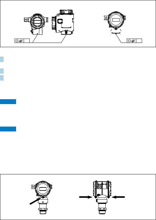
4.4.1Installation instructions
NOTICE
Damage to the device!
If a heated Deltapilot S is cooled during the cleaning process (e.g. by cold water), a vacuum develops for a short time, whereby moisture can penetrate the sensor through the pressure compensation (1).
If this is the case, mount the sensor with the pressure compensation (1) pointing downwards.
1
1
1
•Keep the pressure compensation and GORE-TEX® filter (1) free from contaminations.
•Do not clean or touch process isolating diaphragm with hard or pointed objects.
•The device must be installed as follows in order to comply with the cleanability requirements of the ASME-BPE (Part SD Cleanability):
14 |
|
|
|
|
|
|
|
|
|
|
Endress+Hauser |
|
|
|
|
|
|
|
|
|
|
||
|
|
|
|
|
|
|
|
|
|
||
|
|
|
|
|
|
|
|
|
|
||
|
|
|
|
|
|
|
|
|
|
||
|
|
|
|
|
|
|
|
|
|
||
|
|
|
|
|
|
|
|
|
|
||
|
|
|
|
|
|
|
|
|
|
||
|
|
|
|
|
|
|
|
|
|
||
|
|
|
|
|
|
|
|
|
|

Deltapilot S FMB70 with 4...20 mA HART |
Installation |
|
|
Level measurement
P01-PMP75xxx-11-xx-xx-xx-000 |
Fig. 5: Measuring arrangement for level
•Always install the device below the lowest measuring point.
•Do not install the device at the following positions:
–in the filling curtain
–in the tank outflow
–in the suction area of a pump
–or at a point in the tank that can be affected by pressure pulses from the agitator
•The calibration and functional test can be carried out more easily if you mount the device downstream of a shutoff device.
•Deltapilot S must be included in the insulation for media that can harden when cold.
Pressure measurement in gases
•Mount Deltapilot S with shutoff device above the tapping point so that any condensate can flow into the process.
Pressure measurement in steams
•Mount Deltapilot S with siphon above the tapping point.
•Fill the siphon with liquid before commissioning.
The siphon reduces the temperature to almost the ambient temperature.
Pressure measurement in liquids
• Mount Deltapilot S with the shutoff device below or at the same level as the tapping point.
Endress+Hauser |
15 |

Installation |
Deltapilot S FMB70 with 4...20 mA HART |
|
|
4.4.2Seal for flange mounting
NOTICE
Corrupted measurement results.
The seal is not allowed to press against the process isolating diaphragm as this could affect the measurement result.
Ensure that the seal is not touching the process isolating diaphragm.
|
1 |
2 |
|
|
A0017743 |
Fig. 6: |
|
|
1 |
Process isolating diaphragm |
|
2 |
Seal |
|
4.4.3Wall and pipe mounting (optional)
Endress+Hauser offers a mounting bracket for installation on pipes or walls (for pipe diameters from 1 ¼" to 2").
(2.76) |
3.39) |
70 |
86( |
|
122 (4.8) |
|
158 (6.22) |
|
ø42...60 (1.65...2.36) |
(2.05) |
(0.24) |
52 |
ø6 |
|
140 (5.51) |
|
175 (6.89) |
A0028493
Engineering unit mm (in)
Please note the following when mounting:
•Devices with capillary tubes: mount capillaries with a bending radius 100 mm (3.94 in).
•When mounting on a pipe, tighten the nuts on the bracket uniformly with a torque of at least 5 Nm (3.69 lbs ft).
16 |
Endress+Hauser |
Deltapilot S FMB70 with 4...20 mA HART |
Installation |
|
|
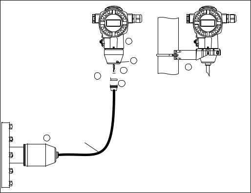
4.4.4Assembling and mounting the "separate housing" version
7
6
8

 5 3
5 3 


 2
2
1 |
r 120 mm |
P01-FMB70xxx-11-xx-xx-xx-003
Fig. 7: "Separate housing" version
1In the "separate housing" version, the sensor is supplied with process connection and cable fitted.
2Cable with connection jack
3Pressure compensation
5Plug
6Locking screw
7Housing fitted with housing adapter, included
8Mounting bracket suitable for wall and pipe mounting, included
Assembly and mounting
1.Connect plug (item 5) into the corresponding connection jack of the cable (item 2).
2.Plug the cable into the housing adapter (item 7).
3.Tighten the locking screw (item 5).
4.Mount the housing on a wall or pipe using the mounting bracket (item 8). When mounting on a pipe, tighten the nuts on the bracket uniformly with a torque of at least 5 Nm (3.69 lbs ft).
Mount the cable with a bending radius (r) 120 mm (4.72 in).
Endress+Hauser |
17 |
Installation |
Deltapilot S FMB70 with 4...20 mA HART |
|
|
4.4.5Rotating the housing
The housing can be rotated up to 380° by loosening the Allen screw.
T14 |
|
|
|
|
|
|
|
|
|
|
|
|
|
T15 |
|
|
|
|
|
|
|
|
T17 |
|||||||||||||
|
|
|
|
|
|
|
|
|
|
|
|
|
|
|
|
|
|
|
|
|
|
|
|
|
|
|
|
|
|
|
|
|
|
|
|
|
|
|
|
|
|
|
|
|
|
|
|
|
|
|
|
|
|
|
|
|
|
|
|
|
|
|
|
|
|
|
|
|
|
|
|
|
|
|
|
|
|
|
|
|
|
|
|
|
|
|
|
|
|
|
|
|
|
|
|
|
|
|
|
|
|
|
|
|
|
|
|
|
|
|
|
|
|
|
|
|
|
|
|
|
|
|
|
|
|
|
|
|
|
|
|
|
|
|
|
|
|
|
|
|
|
|
|
|
|
|
|
|
|
|
|
|
|
|
|
|
|
|
|
|
|
|
|
|
|
|
|
|
|
|
|
|
|
|
|
|
|
|
|
|
|
|
|
|
|
|
|
|
|
|
|
|
|
|
|
|
|
|
|
|
|
|
|
|
|
|
|
|
|
|
|
|
|
|
|
|
|
|
|
|
|
|
|
|
|
|
|
|
|
|
|
|
|
|
|
|
|
|
|
|
|
|
|
|
|
|
|
|
|
|
|
|
|
|
|
|
|
|
2 |
3 |
A0019996
1.T14 and T15 housing: Loosen setscrew with a 2 mm (0.08 in) Allen key. T17 housing: Loosen setscrew with a 3 mm (0.12 in) Allen key.
2.Rotate housing (max. up to 380 °).
3.Retighten setscrew with 1 Nm (0,74 lbf ft.
4.4.6Closing the housing cover
NOTICE
Devices with EPDM cover seal - transmitter leakiness!
Mineral-based, animal-based or vegetable-based lubricants cause the EPDM cover seal to swell and the transmitter to become leaky.
The thread is coated at the factory and therefore does not require any lubrication.
NOTICE
The housing cover can no longer be closed.
Damaged thread!
When closing the housing cover, please ensure that the thread of the cover and housing are free from dirt, e.g. sand.If you feel any resistance when closing the cover, check the thread on both again to ensure that they are free from dirt.
Close cover on a hygenic stainless steel housing (T17)
P01-FMB70xxx-17-xx-xx-xx-001
Fig. 8: |
Close cover |
The covers for the terminal and electronics compartment are hooked into the casing and closed with a screw. These screws should be finger-tightened (2 Nm (1.48 lbf ft)) to the stop to ensure that the covers sit tightly.
18 |
Endress+Hauser |
Deltapilot S FMB70 with 4...20 mA HART |
Installation |
|
|
4.4.7Mounting of the profile seal for universal process mounting adapter
For details on mounting, see KA00096F/00/A3.
4.5Post-installation check
After installing the device, carry out the following checks:
•Are all screws firmly tightened?
•Are the housing covers screwed down tight?
Endress+Hauser |
19 |

Wiring |
Deltapilot S FMB70 with 4...20 mA HART |
|
|
5 Wiring
5.1Connecting the device
! WARNING
Risk of electric shock!
If the operating voltage is > 35 VDC: Dangerous contact voltage at terminals.
In a wet environment, do not open the cover if voltage is present.
!WARNING
Limitation of electrical safety due to incorrect connection!
•Risk of electric shock and/or explosion in hazardous areas! In a wet environment, do not open the cover if voltage is present.
•When using the measuring device in hazardous areas, installation must comply with the corresponding national standards and regulations and the Safety Instructions or Installation or Control Drawings.
•Devices with integrated overvoltage protection must be earthed.
•Protective circuits against reverse polarity, HF influences and overvoltage peaks are installed.
•The supply voltage must match the supply voltage on the nameplate. ( ä 10, Section 3.2.1 "Nameplate")
•Switch off the supply voltage before connecting the device.
•Remove housing cover of the terminal compartment.
•Guide cable through the gland. Preferably use twisted, screened two-wire cable.
•Connect device in accordance with the following diagram.
•Screw down housing cover.
•Switch on supply voltage.
|
|
|
10.5 V DC |
|
|
|
|
|
|
|
11.5 V DC |
|
|
4…20 mA |
|
|
Test |
|
|
|
|
Test |
|
|
4... 20mA |
Test |
|
|
|
|
|
|
|
|
|
|
|
|
|
|
|
4... 20mA |
Test |
|
|
|
|
|
|
|
P01-xMx7xxxx-04-xx-xx-xx-001 |
Fig. 9: Electrical connection 4 to 20 mA HART
Observe also Section 5.2.1 "Supply voltage", ä 22.
1Housing
2Jumper for 4 to 20 mA test signal.
ä 22, Section 5.2.1 "Taking 4 to 20 mA test signal" part.
3Internal earth terminal
4External earth terminal
54 to 20 mA test signal between plus and test terminal
6Minimum supply voltage = 10.5 V DC, jumper is inserted in accordance with the illustration.
7Minimum supply voltage = 11.5 V DC, jumper is inserted in "Test" position.
8Devices with integrated overvoltage protection are labelled OVP (overvoltage protection) here.
20 |
Endress+Hauser |
Loading...