


CLS50D
Table of contents
 Loading...
Digital sensor with Memosens protocol or analog
sensor
Application
Indumax CLS50D or CLS50 sensor is particularly suitable for use in the chemical and
process technology sectors. The six-decade measuring range and the excellent
chemical resistance properties of the materials in contact with the medium (PFA or
PEEK) make it possible to use this sensor in a wide range of applications, such as:
• Concentration measurement of acids and bases
• Quality monitoring of chemical products in tanks and pipes
• Phase separation of product/product mixtures
The digital sensor CLS50D is used in conjunction with the Liquiline CM44x/R or
Liquiline M CM42, while the analog sensor CLS50 is used with the Liquiline M CM42
or Liquisys CLM223/253.
Your benefits
• High durability
– High chemical resistance thanks to PFA coating
– PEEK version for temperatures up to 180 °C (356 °F)
• Low risk of soiling
– Dirt-repellent PFA surface
– Large sensor opening
• Easy installation
– Can be installed in pipes ≥ DN 80
– Total cable length up to 55 m (180 ft)
• Large measuring range from 2 μS/cm to 2000 mS/cm
• Integrated, coated Pt 100 temperature sensor, error class A
• Ex approval Ex ia IIC T4/T6
Other advantages of Memosens technology
• Maximum process safety
• Data security thanks to digital data transmission
• Very easy to use as sensor data saved in the sensor
• Recording of sensor load data in the sensor enables predictive maintenance
Products
Solutions Services
Technical Information
Indumax CLS50D/CLS50
Inductive conductivity sensor for standard, Ex and
high-temperature applications
TI00182C/07/EN/17.18
71420290
2018-10-31

Indumax CLS50D/CLS50
2 Endress+Hauser
Function and system design
Measuring principle
Inductive conductivity measurement
An oscillator (1) generates an alternating magnetic field in the primary coil (5), which induces a
current flow (4) in the medium. The strength of the current depends on the conductivity and thus on
the ion concentration in the medium. The current flow in the medium, in turn, generates a magnetic
field in the secondary coil (3). The resulting induced current is measured by the receiver (2) and used
to determine the conductivity.
3
4
A0024926
1
2
3
4
5
Oscillator
Receiver
Secondary coil
Current flow in the medium
Primary coil
Advantages of inductive conductivity measurement:
• No electrodes and therefore no polarization effects
• Accurate measurement in media with a high degree of
pollution and a tendency to form buildup
• Complete galvanic isolation of the measurement and the
medium
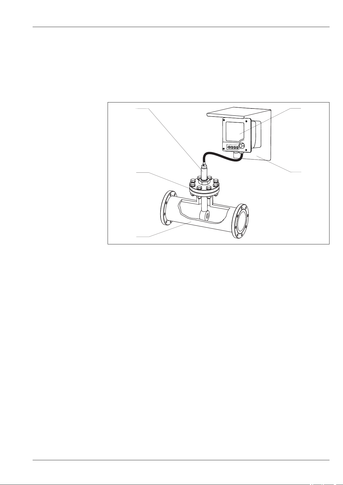
Measuring system CLS50D
A complete measuring system comprises:
• A CLS50D inductively measuring conductivity sensor with fixed cable
• A transmitter, e.g. Liquiline CM44x
Optional:
• Weather protection for the field installation of the transmitter
• Assembly to install the sensor in vessels or pipes, e.g. CLA111
1 2
3
4
5
A0024929
1 Example of a measuring system
1 Liquiline CM44x transmitter
2 Protective cover
3 Pipe nozzle with flange DN50 PN16
4 CLS50D sensor, version with flange DN50 PN16 and fixed cable with M12 connector
5 Pipe
Indumax CLS50D/CLS50
Endress+Hauser 3
CLS50
A complete measuring system comprises:
• A CLS50 inductively measuring conductivity sensor with fixed cable
• A transmitter, e.g. Liquiline M CM42
Optional:
• Weather protection for the field installation of the transmitter
• Assembly to install the sensor in vessels or pipes, e.g. CLA111
21
3
4
5
A0024930
2 Example of a measuring system
1 CLS50 sensor, version with lap joint flange and fixed cable with ferrules
2 Liquiline CM42 transmitter
3 Protective cover
4 Pipe
5 Pipe nozzle with flange connection

Indumax CLS50D/CLS50
4 Endress+Hauser
Communication and data processing (CLS50D only)
Communication with the transmitter
Always connect digital sensors with Memosens technology to a transmitter with Memosens
technology. Data transmission to a transmitter for analog sensors is not possible.
Digital sensors can store measuring system data in the sensor. These include the following:
• Manufacturer data
– Serial number
– Order code
– Date of manufacture
• Calibration data
– Calibration date
– Cell constant
– Delta cell constant
– Number of calibrations
– Serial number of the transmitter used to perform the last calibration
• Operating data
– Temperature application range
– Conductivity application range
– Date of initial commissioning
– Maximum temperature value
– Hours of operation at high temperatures
Input
Measured variables
• Conductivity
• Temperature
Measuring ranges
Conductivity
2 μS/cm to 2000 mS/cm (uncompensated)
Temperature -20 to +180 °C (-4 to +350 °F)
Cell constant
k = 1.98 cm
–1
Measuring frequency
2 kHz
Temperature measurement CLS50D
Pt1000 (Class A according to IEC 60751)
CLS50
Pt100 (Class A according to IEC 60751)

Indumax CLS50D/CLS50
Endress+Hauser 5
Power supply
Electrical connection
The sensor is supplied with a fixed cable. The cable between the sensor and transmitter can be
extended using the CYK11 (CLS50D) or CLK6 (CLS50) measuring cable (does not apply for use in a
hazardous environment).
GY
GY
GN
WH
BN
YE
PK
Shield
-
Com A
-
+
Com B
+
Memosens
U
U
Additional
sensor supply
A0017984
3 CYK11 for extension of CLS50D
Total cable length (max.): 100 m (330 ft)
WH
RD
Pt 100
YE
GN
RD
WH
BU
BN n.c.
RD
BU
A0024937
4 CLK6 for extension of CLS50
Total cable length (max.): 55 m (180 ft)
CLS50 only:
The residual coupling of the sensor increases when the fixed cable is extended.
Performance characteristics
Conductivity response time
t
95
≤ 2 s
Temperature response time
PEEK version:
t
90
≤ 7 min
PFA version: t
90
≤ 11 min
Maximum measured error
-20 to 100 °C (-4 to 212 °F):
±(5 μS/cm + 0.5 % of reading)
> 100 °C (212 °F): ±(10 μS/cm + 0.5 % of reading)
Repeatability
0.2% of reading
Linearity
1.9 % (only applies in the 1 to 20 mS/cm measuring range)
Loading...