


 Loading...
Operating Instructions
Micropilot M FMR244
Level-Radar
BA00248F/00/EN/13.11
71139064
Valid as of software version: 01.05.00

Brief operating instructions |
Micropilot M FMR244 HART 4 to 20 mA |
|
|
Brief operating instructions
KA235F/00/a2/08.06 Micropilot M FMR240/244/245/250 - Brief operating instructions
52025245
|
000 |
|
Contrast: |
+ |
or |
+ |
|
|
|
|
008 |
|
|
|
measured |
|
|
|
|
|
|
|
|
|
|
|
|
|
|
|
|
|
|
|
|
|
|
|
E dist./ |
|
|
|
value |
|
|
|
|
|
|
|
|
|
|
|
|
|
- + E |
|
- + |
|
|
|
|
|
|
|
E |
meas value |
|
|
|
|
|
|
|
|
|
E |
|
|
|||
|
|
|
|
|
|
|
|
|
|
|
|
||
|
Group |
|
|
|
|
|
|
|
|
|
|
|
|
|
selection |
001 |
002 |
|
003 |
004 |
005 |
006 |
007 |
008 |
051 |
052 |
053 |
|
00 |
media |
tank |
|
medium |
process |
empty |
full |
pipe |
dist./ |
check |
range of |
start |
|
type |
shape |
|
cond. |
cond. |
calibr. |
calibr. |
diameter |
meas value |
distance |
mapping |
mapping |
|
|
basic |
|
|||||||||||
+ |
|
|
|
|
|
|
|
|
|
|
|
|
|
setup |
|
|
|
|
|
|
|
|
|
|
|
|
|
|
- liquid |
- dome |
- unknown |
- standard |
input E |
input F |
only for |
D and L are |
- ok |
confirm |
|
||
|
|
|
|||||||||||
|
01 |
|
ceiling |
- DC: <1.9 |
- calm |
(see sketch) (see sketch) bypass + |
displayed |
- too small |
suggestion |
|
|||
|
- solid |
- horizontal |
- DC: 1.9 … 4 |
surface |
|
|
stilling well |
(see sketch) |
- too big |
or specify |
|
||
|
safety |
|
|
|
|||||||||
|
|
cyl. |
- DC: 4 … 10 |
- add. |
|
|
|
|
- unknown |
range |
|
||
|
settings |
|
|
|
|
|
|
||||||
|
|
- bypass |
- DC: >10 |
agitator |
|
|
|
|
- manual |
|
|
||
|
|
|
|
|
|
|
|
|
|||||
|
04 |
|
… |
|
|
… |
|
|
|
|
|
|
|
|
|
|
|
|
|
|
|
|
|
|
|
|
|
|
linearisation |
|
|
|
|
|
|
|
|
|
|
|
|
|
|
00A |
|
00B |
|
00C |
|
005 |
006 |
|
|
|
05 |
|
vessel / |
|
medium |
|
proscess |
|
empty |
full |
|
|
|
|
silo |
|
cond. |
|
cond. |
|
calibr. |
calibr. |
|
20 mA |
||
extended |
|
|
|
|
|
|
|
|
|
|
|
|
|
|
|
|
|
|
|
|
|
|
|
100% |
|
calibr. |
|
- unknown |
- unknown |
|
- standard |
input E |
input F |
|
||||
|
|
|
|
|||||||||
06 |
|
- metal silo |
- DC: 1.6...1.9 |
- fast change |
(see sketch) (see sketch) |
|
|
|||||
|
- concrete |
- DC: 1.9 …2.5 |
- slow change |
|
|
|
|
|
|
|||
output (HART, FF) |
|
|
|
|
D |
|
||||||
silo |
|
- DC: 2.5 …4 |
- test: no filter |
|
|
|
flange: |
|
||||
profibus param. (PA) |
|
|
|
|
|
|
||||||
- bin / bunker ... |
|
|
|
|
|
reference point of |
E |
|
||||
|
|
|
|
|
|
|
|
|||||
|
|
… |
|
|
|
|
|
|
|
measurement |
|
|
|
|
|
|
|
|
|
|
|
|
|
||
09 |
092 |
|
… … |
|
|
|
|
|
|
F |
|
|
|
|
|
|
|
|
|
|
|
||||
display |
language |
|
|
|
|
|
|
|
|
|||
|
|
|
|
|
|
|
|
|
|
|||
0E |
0E1 |
|
0E2 |
|
|
|
|
|
|
|
L |
|
envelope |
plot settings |
recording |
|
|
|
|
|
|
|
|||
|
|
|
|
|
threaded |
|
|
|||||
curve |
|
|
curve |
|
|
|
|
|
|
|
||
|
|
|
|
|
|
|
connection |
|
|
|||
|
|
|
|
|
|
|
|
|
|
|
4 mA |
|
|
- envel. curve |
- single curve |
|
|
|
|
|
1 ½” BSPT (R 1½”) |
|
|||
|
|
|
|
|
|
|
0% |
|||||
- |
- incl. FAC |
- cyclic |
|
|
|
|
|
or 1½ NPT: |
|
|||
|
0A4 |
|
|
|
|
|
||||||
|
- incl. cust. map |
|
|
|
|
|
… |
reference point of |
|
|
||
|
|
|
|
unlock parameter |
|
|
||||||
|
|
|
|
|
|
|
measurement |
|
|
|||
|
|
|
|
|
|
|
|
|
|
|
|
|
0A |
0A0 |
|
0A1 |
|
… |
= 100: unlocked |
} HART |
|
Solid |
Liquid |
||
diagnostics |
present error |
previous error |
|
|
|
|||||||
|
≠ 100: locked |
|
|
|
|
|||||||
0C |
|
|
|
|
|
= 2457: unlocked |
}PA, FF |
|
|
|
||
system parameter |
|
|
|
|
|
|
|
|||||
|
|
|
|
≠ 2457: locked |
|
|
|
52025245 |
||||
|
|
|
|
|
|
|
|
|
|
|
||
|
|
|
|
|
|
|
|
|
|
|
|
L00-FMR250xx-19-00-00-en-020 |
!Note!This operating manual explains the installation and initial start-up for the level transmitter. All functions that are required for a typical measuring task are taken into account here. In addition, the Micropilot M provides many other functions that are not included in this operating manual, such as optimising the measuring point and converting the measured values.
An overview of all device functions can be found on → ä 86.
The operating manual BA00291F/00/EN "Description of Instrument Functions" provides an extensive description of all device functions, which can be found on the enclosed CD-ROM.
2 |
Endress+Hauser |

Micropilot M FMR244 HART 4 to 20 mA |
Table of contents |
|
|
Table of contents
1 |
Safety instructions . . . . . . . . . . . . . . . . |
4 |
1.1 Designated use . . . . . . . . . . . . . . . . . . . . . . . . . . . . 4 1.2 Installation, commissioning and operation . . . . . . . . 4 1.3 Operational safety and process safety . . . . . . . . . . . . 4 1.4 Notes on safety conventions and symbols . . . . . . . . . 5
2 |
Identification . . . . . . . . . . . . . . . . . . . . |
6 |
2.1 Device designation . . . . . . . . . . . . . . . . . . . . . . . . . 6 2.2 Scope of delivery . . . . . . . . . . . . . . . . . . . . . . . . . . . 9 2.3 Certificates and approvals . . . . . . . . . . . . . . . . . . . . 9 2.4 Registered trademarks . . . . . . . . . . . . . . . . . . . . . . . 9
3 |
Mounting . . . . . . . . . . . . . . . . . . . . . . |
10 |
3.1 Quick installation guide . . . . . . . . . . . . . . . . . . . . . 10 3.2 Incoming acceptance, transport, storage . . . . . . . . . 11 3.3 Installation conditions . . . . . . . . . . . . . . . . . . . . . . 12 3.4 Installation instructions . . . . . . . . . . . . . . . . . . . . . 21 3.5 Post-installation check . . . . . . . . . . . . . . . . . . . . . . 26
4 |
Wiring . . . . . . . . . . . . . . . . . . . . . . . . |
27 |
4.1 Quick wiring guide . . . . . . . . . . . . . . . . . . . . . . . . 27 4.2 Connecting the measuring unit . . . . . . . . . . . . . . . 29 4.3 Recommended connection . . . . . . . . . . . . . . . . . . 32 4.4 Degree of protection . . . . . . . . . . . . . . . . . . . . . . . 32 4.5 Post-connection check . . . . . . . . . . . . . . . . . . . . . . 32
5 |
Operation . . . . . . . . . . . . . . . . . . . . . . |
33 |
5.1 Quick operation guide . . . . . . . . . . . . . . . . . . . . . . 33 5.2 Display and operating elements . . . . . . . . . . . . . . . 35 5.3 Local operation . . . . . . . . . . . . . . . . . . . . . . . . . . . 38 5.4 Display and acknowledging error messages . . . . . . 41 5.5 HART communication . . . . . . . . . . . . . . . . . . . . . . 42
6 Commissioning. . . . . . . . . . . . . . . . . . 45
6.1 Function check . . . . . . . . . . . . . . . . . . . . . . . . . . . 45 6.2 Switching on the measuring device . . . . . . . . . . . . 45 6.3 Basic Setup . . . . . . . . . . . . . . . . . . . . . . . . . . . . . . 46 6.4 Basic Setup with the device display . . . . . . . . . . . . 48
6.5Basic Setup with the
Endress+Hauser operating program . . . . . . . . . . . . 60
7 |
Maintenance. . . . . . . . . . . . . . . . . . . . |
64 |
8 |
Accessories. . . . . . . . . . . . . . . . . . . . . |
65 |
8.1 |
Weather protection cover . . . . . . . . . . . . . . . . . . . |
65 |
8.2 |
Commubox FXA195 HART . . . . . . . . . . . . . . . . . . |
65 |
8.3 |
Commubox FXA291 . . . . . . . . . . . . . . . . . . . . . . . |
65 |
8.4 |
ToF Adapter FXA291 . . . . . . . . . . . . . . . . . . . . . . . |
65 |
8.5 |
Remote display FHX40 . . . . . . . . . . . . . . . . . . . . . |
66 |
9 Trouble-shooting . . . . . . . . . . . . . . . . . 67
9.1 Trouble-shooting instructions . . . . . . . . . . . . . . . . . 67 9.2 System error messages . . . . . . . . . . . . . . . . . . . . . . 68 9.3 Application errors in liquids . . . . . . . . . . . . . . . . . . 70 9.4 Application errors in solids . . . . . . . . . . . . . . . . . . . 72 9.5 Orientation of the Micropilot . . . . . . . . . . . . . . . . . 73 9.6 Spare Parts . . . . . . . . . . . . . . . . . . . . . . . . . . . . . . 75 9.7 Return . . . . . . . . . . . . . . . . . . . . . . . . . . . . . . . . . . 76 9.8 Disposal . . . . . . . . . . . . . . . . . . . . . . . . . . . . . . . . . 76 9.9 Software history . . . . . . . . . . . . . . . . . . . . . . . . . . . 76 9.10 Contact addresses of Endress+Hauser . . . . . . . . . . . 76
10 Technical data . . . . . . . . . . . . . . . . . . . 77
10.1 Additional technical data . . . . . . . . . . . . . . . . . . . . 77
11 Appendix. . . . . . . . . . . . . . . . . . . . . . . 86
11.1 Operating menu HART . . . . . . . . . . . . . . . . . . . . . 86 11.2 Patents . . . . . . . . . . . . . . . . . . . . . . . . . . . . . . . . . 88
Index . . . . . . . . . . . . . . . . . . . . . . . . . . . . . . 89
Endress+Hauser |
3 |
Safety instructions |
Micropilot M FMR244 HART 4 to 20 mA |
|
|
1 Safety instructions
1.1Designated use
The Micropilot M is a compact radar level transmitter for the continuous, contactless measurement of liquids, pastes, sludge and solids. The device can also be freely mounted outside closed metal vessels because of its operating frequency of about 26 GHz and a maximum radiated pulsed energy of 1 mW (average power output 1 μW). Operation is completely harmless to humans and animals.
1.2Installation, commissioning and operation
The Micropilot M has been designed to operate safely in accordance with current technical, safety and EU standards. If installed incorrectly or used for applications for which it is not intended, however, it is possible that application-related dangers may arise, e. g. product overflow due to incorrect installation or calibration. For this reason, the instrument must be installed, connected, operated and maintained according to the instructions in this manual: personnel must be authorised and suitably qualified. The manual must have been read and understood, and the instructions followed. Modifications and repairs to the device are permissible only when they are expressly approved in the manual.
1.3Operational safety and process safety
Alternative monitoring measures must be taken to ensure operational safety and process safety during configuration, testing and maintenance work on the device.
Hazardous areas
Measuring systems for use in hazardous environments are accompanied by separate "Ex documentation", which is an integral part of this Operating Manual. Strict compliance with the installation instructions and ratings as stated in this Additional documentation is mandatory.
•Ensure that all personnel are suitably qualified.
•Observe the specifications in the certificate as well as national and local regulations.
1.3.1FCC approval
This device complies with part 15 of the FCC Rules. Operation is subject to the following two conditions:
1.This device may not cause harmful interference.
2.This device must accept any interference received, including interference that may cause undesired operation.
"Caution!Changes or modifications not expressly approved by the part responsible for compliance could void the user’s authority to operate the equipment.
4 |
Endress+Hauser |

Micropilot M FMR244 HART 4 to 20 mA |
Safety instructions |
|
|
1.4Notes on safety conventions and symbols
In order to highlight safety-relevant or alternative operating procedures in the manual, the following conventions have been used, each indicated by a corresponding symbol in the margin.
Safety conventions
# |
Warning! |
|
A warning highlights actions or procedures which, if not performed correctly, will lead to personal |
||
|
injury, a safety hazard or destruction of the instrument. |
|
|
|
|
" |
Caution! |
|
Caution highlights actions or procedures which, if not performed correctly, may lead to personal |
||
|
injury or incorrect functioning of the instrument. |
|
|
|
|
! |
Note! |
|
A note highlights actions or procedures which, if not performed correctly, may indirectly affect |
||
|
operation or may lead to an instrument response which is not planned. |
|
|
|
|
Explosion protection |
||
|
|
|
0 |
Device certified for use in explosion hazardous area |
|
If the device has this symbol embossed on its name plate it can be installed in an explosion hazardous |
||
|
area. |
|
|
|
|
- |
Explosion hazardous area |
|
Symbol used in drawings to indicate explosion hazardous areas. Devices located in and wiring |
||
entering areas with the designation “explosion hazardous areas” must conform with the stated type |
||
|
of protection. |
|
|
|
|
. |
Safe area (non-explosion hazardous area) |
|
Symbol used in drawings to indicate, if necessary, non-explosion hazardous areas. Devices located in |
||
|
safe areas still require a certificate if their outputs run into explosion hazardous areas. |
|
|
|
|
Electrical symbols |
||
|
|
|
% |
Direct voltage |
|
A terminal to which or from which a direct current or voltage may be applied or supplied. |
||
|
|
|
& |
Alternating voltage |
|
A terminal to which or from which an alternating (sine-wave) current or voltage may be applied or |
||
|
supplied. |
|
|
|
|
) |
Grounded terminal |
|
A grounded terminal, which as far as the operator is concerned, is already grounded by means of an |
||
|
earth grounding system. |
|
|
|
|
* |
Protective grounding (earth) terminal |
|
A terminal which must be connected to earth ground prior to making any other connection to the |
||
|
equipment. |
|
|
|
|
+ |
Equipotential connection (earth bonding) |
|
A connection made to the plant grounding system which may be of type e. g. neutral star or |
||
|
equipotential line according to national or company practice. |
|
|
|
|
t >85°C |
Temperature resistance of the connection cables |
|
States, that the connection cables must be resistant to a temperature of at least 85 °C (185 °F). |
||
|
||
|
|
|
Endress+Hauser |
5 |

Identification |
Micropilot M FMR244 HART 4 to 20 mA |
|
|
2 Identification
2.1Device designation
2.1.1Nameplate
The following technical data are given on the instrument nameplate:
 ENDRESS+HAUSER
|
1 |
|
|
Order Code: |
|
|
2 |
Ser.-No.: |
|
3 |
|
4 |
|
|
|
|
5 |
|
|
|
|
6 |
|
7 |
|
|
|
|
8 |
|
|
9 |
10 |
|
11 |
12 |
|
|
|
13 |
14 |
15 |
16 |
17
18
19
20
if modification X = see sep. label
Dat./Insp.: 21
Typenschild-FMxxxx-xx
Information on the nameplate of the Micropilot M
1Instrument designation
2Order code
3Serial number
4Process pressure
5Process temperature
6Length (optional)
7Power supply
8Current supply
9Ambient temperature
10Cable specification
11Factory sealed
12Radio equipment number
13TÜV identification mark
14Certificate symbol (optional) e.g. Ex, NEPSI
15Certificate symbol (optional) e.g. 3A
16Certificate symbol (optional) e.g. SIL, FF
17Place of production
18Degree of protection e.g. IP65, IP67
19Certificates and approvals
20Document number of safety instructions e.g. XA, ZD, ZE
21Dat./Insp. xx / yy (xx = week of production, yy = year of production)
6 |
Endress+Hauser |

Micropilot M FMR244 HART 4 to 20 mA |
Identification |
|
|
2.1.2Ordering structure
This overview does not mark options which are mutually exclusive.
10Approval
A Non-hazardous area
F Non-hazardous area, WHG
2 ATEX II 1/2G EEx ia IIC T6, XA note safety instruction (XA) (electrostatic charging)!
7 ATEX II 1/2G EEx ia IIC T6, WHG, XA note safety instruction (XA) (electrostatic charging)! 5 ATEX II 1/2G EEx d [ia] IIC T6, XA note safety instruction (XA) (electrostatic charging)!
H ATEX II 1/2G EEx ia IIC T6, ATEX 3D, XA note safety instruction (XA) (electrostatic charging)! B ATEX II 1/2D, Alu blind cover, XA
C ATEX II 1/3D, XA
G ATEX II 3G EEx nA II T6
S FM IS - Cl.I Div.1 Gr. A-D, zone 0, 1, 2 T FM XP - Cl.I Div.1 Group A-D, zone 1, 2 N CSA General Purpose
U CSA IS - Cl.I Div.1 Group A-D, zone 0, 1, 2 V CSA XP - Cl.I Div.1 Group A-D, zone 1, 2 K TIIS EEx ia IIC T4
L TIIS EEx d [ia] IIC T4
D IECEx Zone 0/1, Ex ia IIC T6, XA note safety instruction (XA) (electrostatic charging)!
E IECEx Zone 0/1, Ex d (ia) IIC T6, XA note safety instruction (XA) (electrostatic charging)! I NEPSI Ex ia IIC T6
J NEPSI Ex d (ia) ia IIC T6 R NEPSI Ex nAL IIC T6
Y Special version, TSP-no. to be spec.
20Antenna
2 40mm/1-1/2", PTFE encapsulated
4 80mm/3", PP cladded
9 Special version, TSP-no. to be spec.
30 |
|
|
Antenna Seal; Temperature |
|
|
|
|
S |
Silicone; -40...80°C/-40…176°F |
|
|
|
V |
FKM Viton GLT; -40…130°C/-40…266°F |
|
|
|
Y |
Special version, TSP-no. to be spec. |
40 |
|
|
|
Process Connection |
|
|
|
|
|
GGS |
Thread ISO228 G1-1/2, PVDF |
|
|
|
|
GNS |
Thread ANSI NPT1-1/2, PVDF |
|
|
|
|
XME |
Mounting bracket, 304 |
|
|
|
|
XRX |
W/o slip on flange/mounting bracket, customer side connection |
|
|
|
|
XVG |
UNI slip on flange 3"/DN80/80, PP max 4bar abs/58psia, suitable for 3" 150lbs/DN80 PN16/10K |
|
|
|
|
|
80 |
|
|
|
|
XXG |
UNI slip on flange 4"/DN100/100, PP |
|
|
|
|
|
max 4bar abs/58psia, suitable for 4" 150lbs / DN100 PN16 / 10K 100 |
|
|
|
|
X1G |
UNI slip on flange 6"/DN150/150, PP |
|
|
|
|
|
max 4bar abs/58psia, suitable for 6" 150lbs / DN150 PN16 / 10K 150 |
|
|
|
|
YY9 |
Special version, TSP-no. to be spec. |
50 |
|
|
|
|
Output; Operation |
|
|
|
|
|
|
A |
4-20mA SIL HART; 4-line display VU331, envelope curve display on site |
|
|
|
|
|
B |
4-20mA SIL HART; w/o display, via communication |
|
|
|
|
|
K |
4-20mA SIL HART; Prepared for FHX40, remote display (Accessory) |
|
|
|
|
|
C |
PROFIBUS PA; 4-line display VU331, envelope curve display on site |
|
|
|
|
|
D |
PROFIBUS PA; w/o display, via communication |
|
|
|
|
|
L |
PROFIBUS PA; Prepared for FHX40, remote display (Accessory) |
|
|
|
|
|
E |
FOUNDATION Fieldbus; 4-line display, envelope curve display on site |
|
|
|
|
|
F |
FOUNDATION Fieldbus; w/o display, via communication |
|
|
|
|
|
M |
FOUNDATION Fieldbus; Prepared for FHX40, remote display (Accessory) |
|
|
|
|
|
Y |
Special version, TSP-no. to be spec. |
60 |
|
|
|
|
|
Housing |
||
|
|
|
|
|
|
A |
F12 Alu, coated IP65 NEMA4X |
|
|
|
|
|
|
|
C |
T12 |
Alu, coated IP65 NEMA4X, separate conn. compartment |
|
|
|
|
|
|
D |
T12 |
Alu, coated IP65 NEMA4X, separate conn. compartment, OVP=overvoltage protection |
|
|
|
|
|
|
Y |
Special version, TSP-no. to be spec. |
|
|
|
|
|
|
|
|
|
|
70 |
|
|
|
|
|
|
Cable entry |
|
|
|
|
|
|
|
|
2 |
Gland M20 (EEx d > thread M20) |
|
|
|
|
|
|
|
3 |
Thread G1/2 |
|
|
|
|
|
|
|
4 |
Thread NPT1/2 |
Endress+Hauser |
7 |
Identification |
|
|
|
|
|
|
|
|
|
Micropilot M FMR244 HART 4 to 20 mA |
|
|
|
|
|
|
|
|
|
|
|
|
|
|
|
|
|
|
|
|
|
|
|
|
|
|
70 |
|
|
|
|
|
|
Cable entry |
|||
|
|
|
|
|
|
|
|
5 |
Plug M12 |
||
|
|
|
|
|
|
|
|
6 |
Plug 7/8" |
||
|
|
|
|
|
|
|
|
9 |
Special version, TSP-no. to be spec. |
||
|
|
|
|
|
|
|
|
|
|
|
|
|
80 |
|
|
|
|
|
|
|
Additional option |
||
|
|
|
|
|
|
|
|
|
A |
Basic version |
|
|
|
|
|
|
|
|
|
|
F |
Advanced dynamics, max. MB=70m liquids, max. MB=15m solids, |
|
|
|
|
|
|
|
|
|
|
|
MB=measuring range |
|
|
|
|
|
|
|
|
|
|
H |
5-point linearity protocol, see additional spec. |
|
|
|
|
|
|
|
|
|
|
L |
5-point, advanced dynamics, 5-point linearity protocol, see additional spec., |
|
|
|
|
|
|
|
|
|
|
|
Advanced dynamics, max MB=70m liquids, max MB=15m solids, MB=measuring |
|
|
|
|
|
|
|
|
|
|
|
range |
|
|
|
|
|
|
|
|
|
|
S |
GL/ABS/NK marine certificate |
|
|
|
|
|
|
|
|
|
|
Y |
Special version, TSP-no. to be spec. |
|
|
|
|
|
|
|
|
|
|
|
|
|
|
995 |
|
|
|
|
|
|
|
|
Marking |
|
|
|
|
|
|
|
|
|
|
|
1 |
Tagging (TAG) |
|
|
|
|
|
|
|
|
|
|
2 |
Bus address |
|
|
|
|
|
|
|
|
|
|
|
|
|
|
|
|
|
|
|
|
|
|
|
|
|
FMR244- |
|
|
|
|
|
|
|
|
|
Complete product designation |
8 |
Endress+Hauser |
Micropilot M FMR244 HART 4 to 20 mA |
Identification |
|
|
2.2Scope of delivery
"Caution!It is essential to follow the instructions concerning the unpacking, transport and storage of measuring instruments given in the chapter "Incoming acceptance, transport, storage", → ä 11!
The scope of delivery consists of:
• Assembled instrument
• Accessories (→ ä 65)
• Endress+Hauser oprating program on the enclosed CD-ROM
• Brief operating instructions KA01009F/00/EN for quick commissioning
• Brief operating instructions KA00235F/00/A2 (basic setup/troubleshooting), housed in the instrument)
• Approval documentation: if this is not included in the operating manual
• CD-ROM with further documentation, e. g. - Technical Information
- Operating Instructions
- Description of Intrument Functions
2.3Certificates and approvals
CE mark, declaration of conformity
The device is designed to meet state-of-the-art safety requirements, has been tested and left the factory in a condition in which it is safe to operate. The device complies with the applicable standards and regulations as listed in the EC declaration of conformity and thus complies with the statutory requirements of the EC directives. Endress+Hauser confirms the successful testing of the device by affixing to it the CE mark.
2.4Registered trademarks
KALREZ®, VITON®, TEFLON®
Registered trademark of the company, E.I. Du Pont de Nemours & Co., Wilmington, USA
TRI-CLAMP®
Registered trademark of the company, Ladish & Co., Inc., Kenosha, USA
HART®
Registered trademark of HART Communication Foundation, Austin, USA
ToF®
Registered trademark of the company Endress+Hauser GmbH+Co. KG, Maulburg, Germany
PulseMaster®
Registered trademark of the company Endress+Hauser GmbH+Co. KG, Maulburg, Germany
PhaseMaster®
Registered trademark of the company Endress+Hauser GmbH+Co. KG, Maulburg, Germany
Endress+Hauser |
9 |

Mounting |
Micropilot M FMR244 HART 4 to 20 mA |
|
|
3 Mounting
3.1Quick installation guide
#Observe orientation when installing!
Installation in tank (free space):
Mark on process connector facing the nearest tank wall!
mark at threaded boss
90° |
90° |
|
|
|
90° |
|
G 1½” |
|
90° |
or |
|
1½ NPT |
||
|
||
|
90° |
Installation in stilling well:
Mark on process connector pointed towards the slots or vent holes!
mark at threaded boss
90°
G 1½” or
1½ NPT
F12 or T12 housing
Caution!
Tighten instrument only at the threaded boss.
AF60
 60
60
max. torque
20 Nm (14.75 lbf ft)
Turn housing
The housing can be turned 350° in order to simplify access to the
display and the terminal compartment
F12 housing
2
3
1
T12 housing
2
3
1
Allen key
4 mm (0.16 in)
max. torque 0.5 Nm (0.37 lbf ft)
L00-FMR244xx-17-00-00-en-001
10 |
Endress+Hauser |
Micropilot M FMR244 HART 4 to 20 mA |
Mounting |
|
|
3.2Incoming acceptance, transport, storage
3.2.1Incoming acceptance
Check the packing and contents for any signs of damage.
Check the shipment, make sure nothing is missing and that the scope of supply matches your order.
3.2.2Transport
"Caution!
Follow the safety instructions and transport conditions for instruments of more than
18 kg (39.69 lbs). Do not lift the measuring instrument by its housing in order to transport it.
3.2.3Storage
Pack the measuring instrument so that is protected against impacts for storage and transport. The original packing material provides the optimum protection for this.
The permissible storage temperature is -40 °C to +80 °C (-40 °F to +176 °F) or -50 °C to +80 °C (-58 °F to +176 °F).
Endress+Hauser |
11 |

Mounting |
Micropilot M FMR244 HART 4 to 20 mA |
|
|
3.3Installation conditions
3.3.1Dimensions
Housing dimensions
max. 110 (4.33) |
|
65 (2.56) |
||
|
|
|
|
|
|
|
|
|
|
 ENDRESS+HAUSER
F12 housing (Aluminium)
mm (in)
78 (3.07)
08) |
|
(ø5. |
.91) |
ø129 |
150(5 |
|
|
85 (3.35) |
|
|
|
L00-F12xxxx-06-00-00-en-001 |
|
max. 100 (4.33) |
94 (3.7) |
65 (2.56) |
78 (3.07) |
|
|
|
ENDRESS+HAUSER |
08) |
|
|
|
|
|
|
|
|
|
ø129(ø5. |
162(6.38) |
|
|
T12 housing |
|
|
|
|
(Aluminium) |
|
|
mm (in) |
|
|
85 (3.35) |
|
|
|
|
|
|
|
|
|
L00-T12xxxx-06-00-00-en-001 |
|
12 |
Endress+Hauser |

Micropilot M FMR244 HART 4 to 20 mA |
Mounting |
|
|
Process connection
|
standard |
|
mounting bracket * optional |
||
) |
|
E+H UNI** |
6.58 |
|
|
|
flange DN80 |
|
167.1( |
|
|
(5.35) |
PBT |
PBT |
135.9 |
15 |
0.59) |
|
|
( |
R |
|
|
|
PP |
PP |
|
|
|
R = reference point of measurement
F12 / T12 housing
Group 20 / Code 4 Code 2
E+H UNI**
flange DN100/ DN150
Screw-in adapter
G1 1/2” , NPT 1 1/2“ |
|
||
39 |
5.14) |
PVDF |
|
|
|
|
|
PBT |
( |
|
|
62.5 (2.46) |
|
84.5 (3.33) |
.79) |
SW60 |
|
|
147(5 |
|
|
|
|
PP |
|
|
|
PTFE
(conform to FDA 21 ø39 (1.54) CFR 177.1550 and
USP <88> Class VI)
suitable for DN80 PN16 / ASME 3” 150 lbs / 10K 80 |
suitable for DN100 PN16 / ASME 4” 150 lbs / 10K 100 |
|
suitable for DN150 PN16 / ASME 6” 150 lbs / 10K 150 |
(4.60) |
|
)32.0 |
73.0(5.18) |
.4(5.02) |
5.30 |
)20.1( |
116.9 |
8 x ø21 |
127 |
||||
|
|
|
|
|
|
|
|
(ø0.83) |
|
|
|
|
ø143 (5.63) |
|
|
ø107.6 (4.24) |
|
|
|
ø107 (4.21) |
|
|
|
|
|
|
|
|
|
8( |
|
|
|
|
|
|
|
|
|
|
) |
|
|
|
|
|
ø75 (2.95) |
|
0(5.61) |
|
|
|
(200.79 |
|
|
|
|
|
|
|
|
|
|
|
||||||
|
|
|
|
|
|
|
|
|
|
||
ø115.6 (4.55) |
|
. |
|
|
Ø 75 (2.95) |
|
|||||
|
|
|
|
|
|
|
|
|
|||
|
|
|
15 |
|
|
|
|
|
|
|
|
|
|
|
|
|
|
|
|
|
|
|
|
ø156.2 (6.15) |
|
ø115 (4.53) |
|
||||||||
|
|
|
|||||||||
|
|
|
|
|
|
|
|
|
|
||
øD
ø200 (7.87)
øB
* Housing T12 : mounting limited only.
øC
**Installation hints: The bolt-holes have been enlarged for adaption of dimensions , therefore, the flange needs to be properly aligned to the counterflange before the bolts are tightened.
Flange |
DN 100 |
DN 150 |
|
|
|
øD |
228.6 (9.00) 285 (11.22) |
|
|
|
|
øB |
190.5 (7.50) 241.3 (9.50) |
|
|
|
|
øC |
175 (6.89) |
240 (9.45) |
|
|
|
d |
19 (0.75) |
23 (0.91) |
mm (in)
d
8.5 (0.35)
15 (0.59)
seal (Viton)
L00-FMR244xx-06-00-00-en-009
Endress+Hauser |
13 |

Mounting |
Micropilot M FMR244 HART 4 to 20 mA |
|
|
3.3.2Engineering hints
Orientation |
|
|
|
• Recommended distance (1) wall – outer |
|
|
|
edge of nozzle: ~1/6 of tank diameter. |
2 |
3 |
4 |
Nevertheless the device should not be |
|
|
|
installed closer than 15 cm (5.91 in) to the |
|
|
|
tankwall. |
|
|
|
• Not in the centre (3), interference can cause |
|
|
|
signal loss. |
1 |
|
|
• Not above the fill stream (4). |
|
|
|
|
|
|
|
• It is recommended to use a weather |
|
|
|
protection cover (2) in order to protect the |
|
|
|
transmitter from direct sun or rain. Assembly |
|
|
|
and disassembly is simply done by means of a |
|
|
|
tension clamp (→ ä 65, "Accessories"). |
|
|
|
Tank installations
•Avoid any installations (1), like limit switches,
temperature sensors, etc., inside the signal beam (→ ä 16, "Beam angle").
•Symmetrical installations (2), i. e. vacuum rings, heating coils, baffles, etc., can also interfere with the measurement.
Optimization options
•Antenna size: the bigger the antenna, the smaller the beam angle, the less interference echoes.
•Mapping: the measurement can be optimized by means of electronic suppression of interference echoes.
•Antenna alignment: "Installation in tank (free space)", → ä 21
•Stilling well: a stilling well can always be used to avoid interference.
•Metallic screens (3) mounted at a slope spread the radar signals and can, therefore, reduce interference echoes.
Please contact Endress+Hauser for further information.
L00-FMR2xxxx-17-00-00-xx-008 |
1 |
α |
3 |
2 |
L00-FMR2xxxx-17-00-00-xx-009 |
14 |
Endress+Hauser |

Micropilot M FMR244 HART 4 to 20 mA |
Mounting |
|
|
Measurement in a plastic tank
If the outer wall of the tank is made of a non-conductive material (e. g. GRP), microwaves can also be reflected off interfering installations outside the signal beam (e. g. metallic pipes (1), ladders (2), grates (3), …). Therefore, there should be no such interfering installations in the signal beam.
Please contact Endress+Hauser for further information.
|
2 |
1 |
3 |
|
L00-FMR2xxxx-17-00-00-xx-013 |
Endress+Hauser |
15 |
Mounting |
Micropilot M FMR244 HART 4 to 20 mA |
|
|
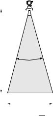
Beam angle
The beam angle is defined as the angle α where the energy density of the radar waves reaches half the value of the maximum energy density (3dB-width). Microwaves are also emitted outside the signal beam and can be reflected off interfering installations. Beam diameter W as function of antenna type (beam angle α) and measuring distance D:
Antenna size (horn |
40 mm (1½") |
|
80 mm (3") |
|
|
|
|
|
|
|
|
|
|
|
|
|
diameter) |
|
|
|
|
|
|
|
|
|
|
|
|
|
|
||
|
|
|
|
|
|
|
|
|
|
|
|
|
|
|
|
|
|
|
|
|
|
|
|
|
|
|
|
|
|
|
|
|
|
Beam angle α |
23° |
|
10° |
|
|
|
|
|
|
|
|
|
|
|
|
|
|
|
|
|
|
|
|
|
|
|
|
|
|
|
|
|
|
Measuring distance |
Beam diameter (W) |
|
|
|
|
|
|
|
|
|
|
|
|
|
||
|
|
|
|
|
|
|
|
|
|
|
|
|
|
|
|
|
(D) |
40 mm (1½") |
|
80 mm (3") |
|
|
|
|
|
|
|
|
|
|
|
|
|
|
|
|
|
|
|
|
|
|
|
|
|
|
|
|||
|
|
|
|
|
|
|
|
|
|
|
|
|
|
|
||
|
|
|
|
|
|
|
|
|
|
|
|
|
|
|
|
|
3 m (9.8 ft) |
1.22 m (4 ft) |
|
0.53 m (1.7 ft) |
|
|
|
|
|
|
|
|
|
|
|
|
|
|
|
|
|
|
|
|
|
|
|
|
|
|
|
|
|
|
6 m (20 ft) |
2.44 m (8 ft) |
|
1.05 m (3.4 ft) |
|
|
|
|
|
|
|
|
|
|
|
|
|
|
|
|
|
|
|
|
|
|
|
|
|
|
|
|
|
|
9 m (30 ft) |
3.66 m (12 ft) |
|
1.58 m (5.2 ft) |
D |
|
|
|
|
|
|
|
|
|
|
|
|
|
|
|
|
|
|
|
|
|
|
|
|
|
|
|
||
12 m (39 ft) |
4.88 m (16 ft) |
|
2.10 m (6.9 ft) |
|
α |
|
|
|
|
|||||||
|
|
|
|
|
|
|
|
|
|
|
|
|||||
|
|
|
|
|
|
|
|
|
|
|
|
|
|
|||
|
|
|
|
|
|
|
|
|
|
|
|
|
|
|
|
|
15 m (49 ft) |
6.10 m (20 ft) |
|
2.63 m (8.63 ft) |
|
|
|
|
|
|
|
|
|
|
|
|
|
|
|
|
|
|
|
|
|
|
|
|
|
|
|
|
|
|
20 m (66 ft) |
8.14 m (27 ft) |
|
3.50 m (11 ft) |
|
|
|
|
|
|
|
|
|
|
|
|
|
|
|
|
|
|
|
|
|
|
|
|
|
|
|
|
|
|
25 m (82 ft) |
10.17 m (33 ft) |
|
4.37 m (14 ft) |
|
|
|
|
|
|
|
|
|
|
|
|
|
|
|
|
|
|
|
|
|
|
|
|
|
|
|
|||
30 m (98 ft) |
|
|
5.25 m (17 ft) |
|
|
|
|
|
|
|
W |
|
|
|
|
|
35 m (115 ft) |
|
|
6.12 m (20 ft) |
|
|
|
|
|
|
|
|
|
|
|
|
|
|
|
|
|
W = 2 |
. D . tan |
α |
|
|
|
|||||||
|
|
|
|
|
|
|
|
|||||||||
40 m (131 ft) |
|
|
7.00 m (23 ft) |
2 |
|
|
|
|||||||||
|
|
|
|
|
|
|
|
|
|
|
|
|
||||
|
|
|
|
|
|
L00-FMR2xxxx-14-00-06-de-027 |
||||||||||
|
|
|
|
|
|
|
|
|
||||||||
45 m (148 ft) |
|
|
7.87 m (26 ft) |
|
|
|
|
|
||||||||
|
|
|
|
|
|
|
|
|
|
|
|
|
|
|||
|
|
|
|
|
|
|
|
|
|
|
|
|
|
|
|
|
60 m (197 ft) |
|
|
10.50 m (34 ft) |
|
|
|
|
|
|
|
|
|
|
|
|
|
|
|
|
|
|
|
|
|
|
|
|
|
|
|
|
|
|
70 m (230 ft) |
|
|
|
|
|
|
|
|
|
|
|
|
|
|
|
|
|
|
|
|
|
|
|
|
|
|
|
|
|
|
|
|
|
16 |
Endress+Hauser |
Micropilot M FMR244 HART 4 to 20 mA |
Mounting |
|
|
Measuring conditions in liquids
Note!
•In case of boiling surfaces, bubbling or tendency for foaming, use FMR230 or FMR231. Depending on its consistence, foam can either absorb microwaves or reflect them off the foam surface. Measurement is possible under certain conditions.
•In case of heavy steam development or condensate the max. measuring range of FMR240 may decrease depending on density, temperature and composition of the steam → use FMR230 or FMR231.
•For the measurement of absorbing gases such as ammonia NH3 or some fluorocarbons 1), please use FMR230 in a stilling well.
A
100%
B |
H |
|
C
0%
Ø D
L00-FMR2xxxx-17-00-00-de-009
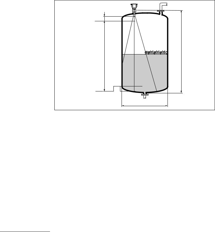
•The measuring range begins, where the beam hits the tank bottom. Particularly with dish bottoms or conical outlets the level cannot be detected below this point.
•In case of media with a low dielectric constant (groups A and B), the tank bottom can be visible through the medium at low levels (low height C). Reduced accuracy has to be expected in this range. If this is not acceptable, we recommend positioning the zero point at a distance C (see Fig.) above the tank bottom in these applications.
•In principle it is possible to measure up to the tip of the antenna with FMR230/231/240. However, due to considerations regarding corrosion and build-up, the end of the measuring range should not be chosen any closer than A (see Fig.) to the tip of the antenna.
For FMR244/245, the end of measuring range should not be chosen closer than A (see Fig.) to the tip of the antenna, especially if there is development of condensate.
•The smallest possible measuring range B depends on the antenna version (see Fig.).
•The tank diameter should be greater than D (see Fig.), the tank height at least H (see Fig.).
A [mm (in)] |
B [m (ft)] |
C [mm (in)] |
D [m (ft)] |
H [m (ft)] |
|
|
|
|
|
150 (5.91) |
> 0.2 (> 0.7) |
50 to 250 (1.97 to 9.84) |
> 0.2 (> 0.7) |
> 0.3 (> 1.0) |
|
|
|
|
|
1)Affected compounds are e. g. R134a, R227, Dymel 152a.
Endress+Hauser |
17 |

Mounting |
Micropilot M FMR244 HART 4 to 20 mA |
|
|
Measuring conditions in solids
•The measuring range begins, where the beam hits the bottom. Particularly with conical outlets the level cannot be detected below this point.
The maximum measuring range can be increased in such applications by using a top target positioner (see Technical Information TI00345F/00/EN).
•In case of media with a low dielectric constant (groups A and B), the bottom can be visible through the medium at low levels. In order to guarantee the required accuracy in these cases, it is recommended to position the zero-point at a distance C above the bottom (see Fig.).
•In principle it is possible to measure up to the tip of the antenna with the Micropilot M. However, due to considerations regarding abrasion and build-up and depending on the orientation of the product surface (angel of repose), the end of the measuring range should be at a distance of A, see Fig. If required, and if some conditions (high DC value, flat angle of repose) are met, shorter distances can be achieved.
A
100%
Measuring range
C
0%
L00-FMR250xx-17-00-00-en-001
A [mm (in)] |
C [mm (in)] |
|
|
approx. 400 (15.7) |
50 to 150 (1.97 to 5.91) |
|
|
18 |
Endress+Hauser |

Micropilot M FMR244 HART 4 to 20 mA |
Mounting |
|
|
Measuring range in liquids
The usable measuring range depends on the size of the antenna, the reflectivity of the medium, the mounting location and eventual interference reflections.
The maximum configurable range is:
•40 m (131 ft) for basic version
•70 m (230 ft) with additional option F (G), → ä 7, "ordering information"
The following tables describe the groups of media as well as the achievable measuring range as a function of application and media group. If the dielectric constant of a medium is unknown, it is recommended to assume media group B to ensure a reliable measurement.
|
|
|
Media group |
DC (εr) |
Examples |
A1.4 to 1.9 non-conducting liquids, e. g. liquefied gas1)
B1.9 to 4 non-conducting liquids, e. g. benzene, oil, toluene, …
C4 to 10 e. g. concentrated acids, organic solvents, esters, aniline, alcohol, acetone, …
D> 10 conducting liquids, e. g. aqueous solutions, dilute acids and alkalis
1)Treat Ammonia NH3 as a medium of group A, i. e. use FMR230 in a stilling well.
Measuring range in solids
The FMR244 with 80 mm (3") antenna or FMR240 with 100 mm (4") horn antenna and additional option F (= advanced dynamics) is also suited for solid applications. The usable measuring range depends on the reflection properties of the medium, the mounting position and interference reflections which may be present. The maximum configurable measuring range for the Micropilot M FMR240 with 100 mm (4") horn antenna and additional option F (= advanced dynamics) is 30 m (98 ft) in solid applications. It is recommended to use the variable flange seal for alignment (see Technical Information TI00345F/00/EN).
Reduction of the max. possible measuring range through:
•Media with poor reflection properties (= small DC). For examples refer to table below.
•Angle of repose.
•Extremely loose surfaces of bulk solids, e. g. bulk solids with low bulk weight for pneumatic filling.
•Build-up, above all of moist products.
The following table describes the media groups and the dielectric constant εr.
|
|
|
|
|
|
Media group |
DC (εr) |
|
Examples |
Signal attenuation |
|
|
|
|
|
|
|
|
|
– |
Plastic granulate |
|
|
A |
1.6 to 1.9 |
– |
White lime, special cement |
19 to 16 dB |
|
|
|
– |
Sugar |
|
|
|
|
|
|
|
|
B |
1.9 to 2.5 |
– |
Portland cement, plaster |
16 to 13 dB |
|
|
|
|
|
|
|
|
|
– |
Grain, seeds |
|
|
C |
2.5 to 4 |
– |
Ground stones |
13 to 10 dB |
|
|
|
– |
Sand |
|
|
|
|
|
|
|
|
D |
4 to 7 |
– |
Naturally moist (ground) stones, ores |
10 to 7 dB |
|
– |
Salt |
||||
|
|
|
|||
|
|
|
|
|
|
|
|
– |
Metallic powder |
|
|
E |
> 7 |
– |
Carbon black |
< 7 dB |
|
|
|
– |
Coal |
|
|
|
|
|
|
|
The respective lower group applies for very loose or loosened bulk solids.
Endress+Hauser |
19 |

Mounting |
Micropilot M FMR244 HART 4 to 20 mA |
|
|
Measuring range depending on vessel type, conditions and product
Standard:
max. measuring range = 40 m (131 ft)
With additional option F (G):
max. measuring range = 70 m (230 ft) min. measuring range = 5 m (16 ft)
*max. recommended measuring range = 20 m (65 ft) with 80 mm (3") antenna, in solids 15 m (49 ft) 1) 2)
1)Larger measuring range in solids available on request.
2)In solids with additional option F (= advanced dynamic), and variable flange seal (see Technical Information TI00345F/00/EN).
Storage tank |
|
Buffer tank |
Process tank with agitator |
Stilling well 1) |
|||||||||||||||||||||||
|
|
|
|
|
|
|
|
|
|
|
|
|
|
|
|
|
|
|
|
|
|
|
|
|
|
|
|
|
|
|
|
|
|
|
|
|
|
|
|
|
|
|
|
|
|
|
|
|
|
|
|
|
|
|
|
|
|
|
|
|
|
|
|
|
|
|
|
|
|
|
|
|
|
|
|
|
|
|
|
|
|
|
|
|
|
|
|
|
|
|
|
|
|
|
|
|
|
|
|
|
|
|
|
|
|
|
|
|
|
|
|
|
|
|
|
|
|
|
|
|
|
|
|
|
|
|
|
|
|
|
|
|
|
|
|
|
|
|
|
|
|
|
|
|
|
|
|
|
|
|
|
|
|
|
|
|
|
|
|
|
|
|
|
|
|
|
|
|
|
|
|
|
|
|
|
|
|
|
|
|
|
|
|
|
|
|
|
|
|
|
|
|
|
|
|
Calm product surface (e. g. intermittent filling, |
Moving surfaces (e. g. continuous filling, |
Turbulent surface. |
|
||||||||||
|
filling from bottom, immersion tubes). |
|
from above, mixing jets). |
|
|
Single stage agitator <60 RPM. |
|
||||||
|
|
|
|
|
|
|
|
|
|
||||
|
40 mm (1½") |
|
* 80 mm (3") |
40 mm (1½") |
* |
80 mm (3") |
40 mm (1½") |
80 mm (3") |
40 mm (1½") |
||||
A B C D |
A B C D |
B C D |
A B C D |
B C D |
B C D |
A, B, C, D |
|||||||
3 |
|
|
|
|
|
2 |
|
|
|
|
1 |
|
|
(9.9) |
|
|
|
|
|
(6.6) |
2.5 |
|
|
|
(3.2) |
|
|
|
5 |
|
|
|
|
|
|
|
|
|
|
|
|
5 |
|
|
|
|
|
(8) |
|
|
|
2 |
|
|
|
(16) |
(16) |
|
|
|
|
|
|
|
|
|
|
|
|
|
8 |
|
|
|
|
|
|
|
|
|
(6.6) |
|
|
|
|
8 |
|
|
|
|
|
|
|
|
2.5 |
|
|
|
(26) |
|
|
|
4 |
|
|
|
|
|
|
||
|
|
|
(26) |
|
|
|
|
|
|
|
(8.2) |
|
|
|
10 |
|
|
|
(13) |
|
|
|
|
|
|
||
|
|
10 |
|
|
|
|
|
|
3 |
|
|
||
|
(32) |
|
|
|
5 |
5 |
5 |
|
|
|
|
||
|
|
|
(32) |
|
|
|
|
(9.8) |
|
|
|||
|
15 |
15 |
|
|
(16) |
(16) |
(16) |
|
|
|
|
|
|
|
|
|
|
|
|
|
|
|
|||||
|
(49) |
(49) |
15 |
|
|
|
|
|
|
|
|
|
|
|
|
25 |
(49) |
|
|
|
|
|
|
|
5 |
5 |
|
|
|
20 |
|
|
7.5 |
|
|
|
|
(16) |
|
||
|
|
(82) |
|
|
|
|
|
|
(16) |
|
|||
|
|
|
|
|
|
|
|
|
|
||||
|
|
|
(65) |
* |
* |
(24) |
|
|
|
|
|
|
|
|
|
|
|
10 |
|
|
|
|
|
8 |
|
||
|
|
|
|
30 |
|
|
10 |
10 |
|
|
(26) |
|
|
|
|
|
|
(98) |
|
(32) |
|
(32) |
(32) |
|
|
|
|
|
|
|
|
|
|
|
|
|
15 |
15 |
|
12 |
20 |
|
|
|
|
|
|
|
|
|
(49) |
(49) |
|
(39) |
(65) |
|
|
|
|
40 |
40 |
|
|
|
|
|
|
15 |
|
|
|
|
|
|
|
|
|
* |
|
|
|||
|
|
|
|
(131) |
(131) |
|
|
|
|
|
(49) |
|
|
|
|
|
|
|
|
|
|
|
|
25 |
|
|
|
|
|
|
|
|
|
|
|
|
|
(82) |
|
|
|
|
|
|
|
|
60 |
|
|
|
|
|
|
|
|
|
|
|
|
|
(197) |
|
|
|
|
|
|
|
|
|
|
|
|
|
|
|
|
|
|
|
|
|
|
Measuring range [m (ft)]
1) Larger measuring range on request
20 |
Endress+Hauser |
Micropilot M FMR244 HART 4 to 20 mA |
Mounting |
|
|
3.4Installation instructions
3.4.1Mounting kit
In addition to the tool needed for flange mounting, you will require the following tool:
•A key AF60 for threaded boss
•4 mm (0.16 in) Allen wrench for turning the housing.
3.4.2Installation in tank (free space)
Optimum mounting position
|
|
mark at threaded boss |
|
|
|
|
G 1½” |
|
|
|
or |
90° |
90° |
|
1½ NPT |
|
|
|
|
|
90° |
|
|
|
|
Caution! |
|
|
|
Use only the |
|
|
|
threaded boss |
|
90° |
|
|
|
|
90° |
AF60 |
|
|
|
max. torque |
|
|
|
60 |
|
|
|
20 Nm (14.75 lbf ft) |
|
|
|
|
|
|
|
|
L00-FMR244xx-17-00-00-en-003 |
Standard installation - 40 mm (1½") antenna
When mounting in a tank, please observe engineering hints (→ ä 14) and the following points:
•Marker is aligned towards tank wall.
•Install the device using the threaded boss (AF60) only. Observe the max. torque of 20 Nm (14.75 lbf ft).
•After mounting, the housing can be turned 350° in order to simplify access to the display and the terminal compartment.
•For optimum measurement, the horn antenna should extend below the nozzle. Nozzle heights up to 500 mm (19.7 in) can be accepted if this should not be possible due to mechanical reasons.
Note!
Please contact Endress+Hauser for application with higher nozzle.
•The antenna must be aligned vertically.
H
Ø D |
L00-FMR244xx-17-00-00-de-002
Antenna size |
40 mm (1½") |
|
|
D [mm (in)] |
39 (1.54) |
|
|
H [mm (in)] |
< 85 (< 3.35) |
|
|
Endress+Hauser |
21 |

Mounting |
Micropilot M FMR244 HART 4 to 20 mA |
|
|
Standard installation - 80 mm (3" antenna)
When mounting in a tank, please observe engineering hints (→ ä 14) and the following points:
•Marker is aligned towards tank wall.
•The marker is located directly below the housing neck on the stainless steel feedthrough.
•As an option for flange mounting, a variable flange seal (see TI00345F/00/EN) can be used to align the device (solid applications).
•If using a mounting bracket, the device can be aligned at the bracket (solid applications), → ä 23.
•After mounting (flange), the housing can be turned 350° in order to simplify access to the display and the terminal compartment.
H
Ø D
L00-FMR244xx-17-00-00-xx-011
Antenna size |
|
80 mm (3") |
|
|
|
|
|
D [mm (in)] |
80 (3.15) |
100 (3.94) |
150 (5.91) |
|
|
|
|
H [mm (in)] |
< 500 (19.7) |
< 500 (19.7) |
< 500 (19.7) |
|
|
|
|
22 |
Endress+Hauser |

Micropilot M FMR244 HART 4 to 20 mA |
Mounting |
|
|
Mounting bracket
Dimensions: |
|
|
|
|
|
R18 |
|
|
|
|
|
|
(8.66) |
120 (4.72) |
|
|
|
7.2) |
220 |
|
|
||
|
|
|
|
||
183( |
|
|
|
|
|
|
5.5(0.22) |
|
|
|
|
|
|
43 |
2.5 |
4 x ø5.5 (0.22) |
|
|
|
(1.69) |
(0.1) |
||
|
|
|
|
||
|
|
85 (3.35) |
|
|
|
|
|
ø9 |
|
12 0.47) |
|
|
|
9 (0.35) |
|
|
|
|
|
|
|
35 |
.38) |
|
|
|
|
|
1 |
|
|
12 |
|
9 |
|
mm (in) |
|
(0.47) |
|
(0.35) |
|
|
|
|
|
|
L00-FMR244xx-06-00-00-xx-008 |
!Note!With T12 housing it‘s not possible to mount the device direct at the ceiling.
Endress+Hauser |
23 |

Mounting |
Micropilot M FMR244 HART 4 to 20 mA |
|
|
3.4.3Installation in stilling well
Optimum mounting position
mark at threaded boss |
|
|
G 1½” |
|
or |
|
1½ NPT |
90° |
|
Caution! |
|
Use only the |
|
threaded boss |
|
AF60 |
|
60 |
max. torque |
20 Nm (14.75 lbf ft) |
|
|
|
|
L00-FMR244xx-17-00-00-en-004 |
Standard installation
For installations in a stilling well, follow the engineering hints (→ ä 14) and note the following points:
•Marker is aligned toward slots.
•Install the device using the threaded boss (AF60) only. Observe the max. torque of 20 Nm (14.75 lbf ft).
•After mounting, the housing can be turned 350° in order to simplify access to the display and the terminal compartment.
•Measurements can be performed through an open full bore ball valve without any problems.
Recommendations for the stilling well
At the construction of a stilling well, please note the following points:
•Metal (no enamel coating, plastic coating on request).
•Constant diameter.
•Stilling well diameter not larger than antenna diameter.
•Weld seam as smooth as possible and on the same axis as the slots.
•Slots offset 180° (not 90°).
•Slot width respectively diameter of holes max. 1/10 of pipe diameter, de-burred. Length and number do not have any influence on the measurement.
•At any transition (i. e. when using a ball valve or mending pipe segments), no gap may be created exceeding 1 mm (0.04 in).
•The stilling well must be smooth on the inside (average roughness Rz ≤6.3 μm (≤ 248 μin)). Use extruded or parallel welded stainless steel pipe. An extension of the pipe is possible with welded flanges or pipe sleeves. Flange and pipe have to be properly aligned at the inside.
•Do not weld through the pipe wall. The inside of the stilling well must remain smooth. In case of unintentional welding through the pipe, the weld seam and any unevenness on the inside need to be carefully removed and smoothened. Otherwise, strong interference echoes will be generated and material build-up will be promoted.
24 |
Endress+Hauser |

Micropilot M FMR244 HART 4 to 20 mA |
|
Mounting |
|
|
|
Examples for the construction of stilling wells
Micropilot M
FMR 244
marker
threaded connection
G 1½" or 1½ NPT stilling well with slots
< 1/10 ø pipe
100 %
< 1/10 ø pipe
150…500 (5.91...19.7)
gap < 1 < 0.04
full bore ball valve
inside of holes deburred
Diameter of opening of ball valve must always be equivalent to pipe diameter.
Avoid edges and constrictions.
0 %

mm (in)
L00-FMR244xx-17-00-00-en-005
Endress+Hauser |
25 |

Mounting |
Micropilot M FMR244 HART 4 to 20 mA |
|
|
3.4.4Turn housing
After mounting, the housing can be turned 350° in order to simplify access to the display and the terminal compartment. Proceed as follows to turn the housing to the required position:
•Undo the fixing screws (1)
•Turn the housing (2) in the required direction
•Tighten up the fixing screws (1). Maximum torque 0.5 Nm (0.37 lbf ft).
F12 housing
2
1
T12 housing
2
1
allen key  4 mm (0.16 in)
max. torque 0.5 Nm (0.37 lbf ft)
L00-FMR2xxxx-17-00-00-en-011
3.5Post-installation check
After the measuring instrument has been installed, perform the following checks:
•Is the measuring instrument damaged (visual check)?
•Does the measuring instrument correspond to the measuring point specifications such as process temperature/pressure, ambient temperature, measuring range, etc.?
•Is the flange marking correctly aligned? (→ ä 10)
•Have the flange screws been tightened up with the respective tightening torque?
•Are the measuring point number and labeling correct (visual check)?
•Is the measuring instrument adequately protected against rain and direct sunlight (→ ä 65)?
26 |
Endress+Hauser |

Micropilot M FMR244 HART 4 to 20 mA |
Wiring |
|
|
4 Wiring
4.1Quick wiring guide
Wiring in F12 housing |
|
|
|
|
|
|
|
|
|
|||
" |
Before connection please note the following: |
|
|
|
|
|
|
|||||
The power supply must be identical to the data on the |
|
|
|
|
|
|
||||||
Caution! |
|
nameplate (1). |
|
|
|
|
|
|
|
|
|
|
|
|
|
|
|
|
|
|
|
|
ENDRESS+HAUSER |
|
Made in Germany |
|
Switch off power supply before connecting up the device. |
|
|
|
MICROPILOT M |
|
D-79689 Maulburg |
|||||
|
|
1 |
Order Code: FMR2xx-14EALJAA2A |
|
|
|||||||
|
|
|
|
|
|
|
|
Ser.-No.: 12345678900 |
IP65 |
|
||
|
Connect Equipotential bonding to transmitter ground |
|
|
|
PN 275 psi |
|
|
|||||
|
|
terminal before connecting up the device. |
|
|
|
Tantenna max. 200°C |
|
|
||||
|
|
|
|
|
LN= 1700MM |
|
|
|||||
|
|
|
|
|
|
|
|
|
|
16 ... 30V DC |
|
|
|
Tighten the locking screw: |
|
|
|
|
2-wire |
|
|
||||
|
|
|
|
|
4 … 20 mA HART |
|
|
|||||
|
|
It forms the connection between the antenna and |
|
|
|
t >85°C |
|
|
||||
|
|
|
|
|
0499 |
X = if modification |
|
|||||
|
|
the housing ground potential. |
|
|
|
|
|
see sep. label |
|
|||
|
|
|
|
|
|
|
Dat./Insp.:34/04 |
250001893-F |
||||
When you use the measuring system in hazardous areas, make sure you comply with |
|
|
||||||||||
national standards and the specifications in the safety instructions (XA’s). |
|
|
|
|
2 |
|||||||
Make sure you use the specific cable gland. |
|
|
|
|
|
|||||||
|
On devices supplied with a certificate, the explosion protection |
|
|
|
|
|||||||
- is designed as follows: |
|
|
|
|
|
|
|
|||||
|
Housing F12 - Ex ia: |
|
|
|
|
|
|
|
||||
|
|
Power supply must be intrinsically safe. |
|
|
|
|
|
|
||||
|
The electronics and the current output are galvanically |
|
|
|
|
|
|
|||||
|
|
separated from the antenna circuit. |
|
|
|
|
|
|
||||
|
Connect up the Micropilot M as follows: |
|
|
|
|
|
|
|||||
|
Unscrew housing cover (2). |
|
|
|
|
#Unplug display connector! |
||||||
|
Remove any display (3) if fitted. |
|
|
|
||||||||
|
|
Remove cover plate from terminal compartment (4). |
|
|
|
|||||||
|
|
|
|
|
|
|
|
|||||
|
Pull out terminal module slightly using pulling loop. |
|
|
|
|
3 |
|
|||||
|
Insert cable (5) through gland (6). |
|
|
|
|
|
|
|||||
|
|
A standard installation cable is sufficient if only the analogue signal |
|
|
||||||||
|
|
is used. Use a screened cable when working with a superimposed |
|
|
|
|||||||
|
|
communications signal (HART). |
|
|
|
|
|
|
||||
- Only ground screening of the line (7) on sensor side. |
|
|
|
|
|
|
||||||
|
Make connection (see pin assignment). |
|
|
|
|
|
|
|||||
|
Re-insert terminal module. |
|
|
|
|
|
|
|
||||
|
Tighten cable gland (6). |
|
|
|
6 |
|
|
|
||||
|
Tighten screws on cover plate (4). |
|
|
|
|
4 |
||||||
|
|
|
|
|
|
|||||||
|
Insert display if fitted. |
|
|
|
|
|
|
|
||||
|
Screw on housing cover (2). |
|
|
|
|
|
|
|
||||
|
Switch on power supply. |
|
|
|
|
|
|
|
||||
|
|
|
|
|
|
5 |
|
|
|
|
|
|
|
|
power |
|
|
|
|
|
|
|
|
|
|
|
|
|
|
|
alternatively |
|
|
|
|
|
|
|
|
|
|
|
|
Commubox FXA195 |
|
|
|
|
|
|
|
|
|
|
|
|
Field Communicator 375, 475 |
|
|
|
|
|
|
|
|
|
|
|
|
7 |
|
|
|
|
|
|
|
4...20 mA |
|
|
|
|
|
|
|
|
|
|
||
|
|
|
|
|
|
1 |
2 |
3 |
4 |
|
|
|
|
|
|
|
|
|
Sealed terminal |
|
|
|
|||
|
|
|
|
|
|
compartment |
|
|
|
|||
|
|
|
|
|
test sockets |
|
|
|
|
|
|
|
|
|
|
|
|
(output current) |
|
|
|
|
|
|
|
|
|
1 |
2 3 |
4 |
plant |
|
|
|
|
|
|
|
|
|
ground |
|
|
|
|
|
|
||||
|
|
L- |
L+ |
I+ |
I- |
|
|
|
|
|
|
|
|
|
|
|
|
|
|
|
|
|
|
L00-FMR2xxxx-04-00-00-en-011 |
|
Endress+Hauser |
|
|
|
|
|
|
|
|
|
|
|
27 |
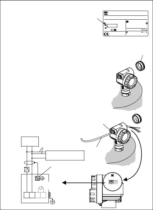
Wiring |
Micropilot M FMR244 HART 4 to 20 mA |
|
|
Wiring in T12 housing |
|
|
|
|
|
|
|||
" |
Before connection please note the following: |
|
|
|
|
||||
● The power supply must be identical to the data on the |
|
|
|
|
|||||
Caution! nameplate (1). |
|
|
ENDRESS+HAUSER |
|
Made in Germany |
||||
|
● Switch off power supply before connecting up the device. |
MICROPILOT M |
|
D-79689 Maulburg |
|||||
|
Order Code: FMR244-14EALJAA2A |
|
|
||||||
|
|
|
|
|
1 |
Ser.-No.: 12345678900 |
IP65 |
|
|
|
● Connect Equipotential bonding to transmitter ground terminal |
Tantenna |
max. 200°C |
|
|
||||
|
|
|
|
|
|
PN 275 psi |
|
|
|
|
before connecting up the device. |
16 ... 30V DC |
|
|
|||||
|
|
|
|
|
|
LN= 1700MM |
|
|
|
|
● Tighten the locking screw: |
2-wire |
|
|
|
||||
|
t >85°C |
|
|
||||||
|
|
|
|
|
|
4 … 20 mA HART |
|
|
|
|
It forms the connection between the antenna and the housing |
|
X = |
see sep. label |
|
||||
|
|
|
|
|
|
0499 |
|
if modification |
|
|
ground potential. |
|
|
|
Dat./Insp.:34/04 |
250001893-F |
|||
When you use the measuring system in hazardous areas, make sure you comply with |
|
|
|
||||||
national standards and the specifications in the safety instructions (XA’s). |
|
|
|
|
|||||
Make sure you use the specific cable gland. |
|
|
|
2 |
|||||
|
|
|
|
|
|
|
|
|
|
|
Connect up the Micropilot M as follows: |
|
|
|
|
||||
|
Before unscrew housing cover (2) at seperate connection room |
|
|
|
|
||||
- turn off the power supply! |
|
|
|
|
|
||||
|
● Insert cable (3) through gland (4). |
|
|
|
|
||||
|
A standard installation cable is sufficient if only the analogue signal is |
|
|
|
|||||
|
used. Use a screened cable when working with a superimposed |
|
|
|
|
||||
|
communications signal (HART). |
|
|
|
|
||||
- Only ground screening of the line (5) on sensor side. |
|
|
|
|
|||||
|
● Make connection (see pin assignment). |
|
|
|
|
||||
|
● Tighten cable gland (4). |
|
|
|
|
|
|||
|
● Screw on housing cover (2). |
|
|
|
|
||||
|
● Switch on power supply. |
|
|
|
|
|
|||
|
|
|
|
|
|
4 |
|
|
|
|
power |
|
|
|
|
|
|
|
|
|
|
|
|
alternatively |
|
|
|
|
|
|
|
|
|
|
3 |
|
|
|
|
|
|
|
|
Commubox FXA195 |
|
|
|
|
|
|
|
|
|
Field Communicator 375, 475 |
|
|
|
|
|
|
|
|
|
5 |
|
|
|
|
|
4...20 mA |
|
|
|
|
|
|
|
|
|
|
|
|
|
test sockets |
1 2 |
3 4 |
|
|
|
|
|
|
|
(output current) |
|
|
|
|
|
|
1 |
2 3 |
4 |
plant |
|
|
|
|
|
|
ground |
|
|
|
|
||||
|
L- |
L+ |
I+ |
I- |
|
|
|
|
|
|
|
|
|
|
|
|
|
L00-FMR2xxxx-04-00-00-en-012 |
|
28 |
|
|
|
|
|
|
Endress+Hauser |
||
Loading...