


Proline Prowirl 72
Table of contents
 Loading...
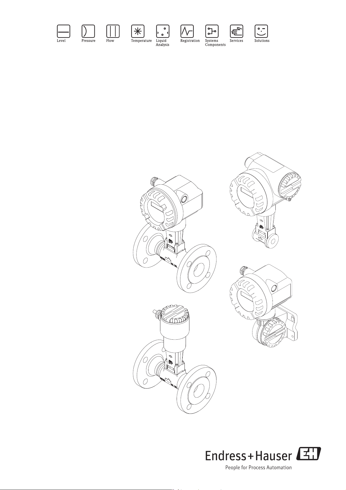
Operating Instructions
Proline Prowirl 72
Vortex Flow Measuring System
8
BA00085D/06/EN/13.11
71154513
valid as of version
V 1.03.XX (device software)

Proline Prowirl 72 PROFIBUS PA
2 Endress + Hauser

Proline Prowirl 72 PROFIBUS PA Table of contents
Table of contents
Table of contents . . . . . . . . . . . . . . . . . . . . . 3
1 Safety instructions . . . . . . . . . . . . . . . . 5
1.1 Designated use . . . . . . . . . . . . . . . . . . . . . . . . . . . . 5
1.2 Installation, commissioning and operation . . . . . . . . 5
1.3 Operational safety . . . . . . . . . . . . . . . . . . . . . . . . . . 5
1.4 Return . . . . . . . . . . . . . . . . . . . . . . . . . . . . . . . . . . . 6
1.5 Notes on safety conventions and icons . . . . . . . . . . . 6
2 Identification . . . . . . . . . . . . . . . . . . . . 7
2.1 Device designation . . . . . . . . . . . . . . . . . . . . . . . . . 7
2.1.1 Nameplate of the transmitter/sensor . . . . . . 7
2.1.2 Nameplate of the sensor, remote version . . . 8
2.1.3 Service nameplate . . . . . . . . . . . . . . . . . . . . 8
2.2 Certificates and approvals . . . . . . . . . . . . . . . . . . . . 9
2.3 Registered trademarks . . . . . . . . . . . . . . . . . . . . . . . 9
3 Installation . . . . . . . . . . . . . . . . . . . . 10
3.1 Incoming acceptance, transport, storage . . . . . . . . . 10
3.1.1 Incoming acceptance . . . . . . . . . . . . . . . . . 10
3.1.2 Transport . . . . . . . . . . . . . . . . . . . . . . . . . 10
3.1.3 Storage . . . . . . . . . . . . . . . . . . . . . . . . . . . 10
3.2 Installation conditions . . . . . . . . . . . . . . . . . . . . . . 11
3.2.1 Dimensions . . . . . . . . . . . . . . . . . . . . . . . . 11
3.2.2 Installation location . . . . . . . . . . . . . . . . . . 11
3.2.3 Orientation . . . . . . . . . . . . . . . . . . . . . . . . 12
3.2.4 Heat insulation . . . . . . . . . . . . . . . . . . . . . 13
3.2.5 Inlet and outlet run . . . . . . . . . . . . . . . . . . 14
3.2.6 Vibrations . . . . . . . . . . . . . . . . . . . . . . . . . 15
3.2.7 Limiting flow . . . . . . . . . . . . . . . . . . . . . . . 15
3.3 Installation . . . . . . . . . . . . . . . . . . . . . . . . . . . . . . 16
3.3.1 Mounting sensor . . . . . . . . . . . . . . . . . . . . 16
3.3.2 Rotating the transmitter housing . . . . . . . . 17
3.3.3 Rotating the local display . . . . . . . . . . . . . . 17
3.3.4 Mounting transmitter (remote) . . . . . . . . . 18
3.4 Post-installation check . . . . . . . . . . . . . . . . . . . . . . 19
4 Wiring . . . . . . . . . . . . . . . . . . . . . . . . 20
4.1 PROFIBUS PA cable specifications . . . . . . . . . . . . . 20
4.1.1 Shielding and grounding . . . . . . . . . . . . . . 22
4.2 Connecting the remote version . . . . . . . . . . . . . . . 22
4.2.1 Connecting the sensor . . . . . . . . . . . . . . . . 22
4.2.2 Cable specifications,
standard connecting cable . . . . . . . . . . . . . 23
4.2.3 Cable specifications,
armored connecting cable . . . . . . . . . . . . . 24
4.3 Connecting the measuring unit . . . . . . . . . . . . . . . 25
4.3.1 Connecting the transmitter . . . . . . . . . . . . 25
4.3.2 Terminal assignment . . . . . . . . . . . . . . . . . 28
4.3.3 Fieldbus connector . . . . . . . . . . . . . . . . . . 28
4.4 Degree of protection . . . . . . . . . . . . . . . . . . . . . . . 30
4.5 Post-connection check . . . . . . . . . . . . . . . . . . . . . . 31
5 Operation . . . . . . . . . . . . . . . . . . . . . . 32
5.1 Quick operation guide . . . . . . . . . . . . . . . . . . . . . . 32
5.2 Display elements . . . . . . . . . . . . . . . . . . . . . . . . . . 33
5.2.1 Display symbols . . . . . . . . . . . . . . . . . . . . . 33
5.3 Error message display . . . . . . . . . . . . . . . . . . . . . . . 34
5.3.1 Type of error . . . . . . . . . . . . . . . . . . . . . . . 34
5.3.2 Type of error message . . . . . . . . . . . . . . . . 34
5.4 Operating options . . . . . . . . . . . . . . . . . . . . . . . . . 35
5.4.1 Operating program "FieldCare" . . . . . . . . . . 35
5.4.2 Operating program "SIMATIC PDM"
(Siemens) . . . . . . . . . . . . . . . . . . . . . . . . . . 35
5.4.3 Commuwin II operating program . . . . . . . . 36
5.4.4 Current device description files . . . . . . . . . 43
5.5 Hardware configuration . . . . . . . . . . . . . . . . . . . . . 44
5.5.1 Switching write protection on/off . . . . . . . 44
5.5.2 Configuring the device address . . . . . . . . . . 45
6 Commissioning . . . . . . . . . . . . . . . . . . 46
6.1 Function check . . . . . . . . . . . . . . . . . . . . . . . . . . . 46
6.1.1 Switching on the measuring device . . . . . . 46
6.2 Commissioning the PROFIBUS interface . . . . . . . . . 47
6.2.1 Commissioning via the Class 2 master . . . . 47
6.3 System integration . . . . . . . . . . . . . . . . . . . . . . . . . 48
6.3.1 Compatibility with previous model
Prowirl 77 . . . . . . . . . . . . . . . . . . . . . . . . . 51
6.4 Cyclic data exchange . . . . . . . . . . . . . . . . . . . . . . . 52
6.4.1 Configuration examples with
Simatic S7 HW-Konfig . . . . . . . . . . . . . . . . 57
6.5 Acyclic data exchange . . . . . . . . . . . . . . . . . . . . . . 62
6.5.1 Class 2 master acyclic (MS2AC) . . . . . . . . . 62
6.5.2 Class 1 master acyclic (MS1AC) . . . . . . . . . 62
7 Maintenance . . . . . . . . . . . . . . . . . . . 63
8 Accessories . . . . . . . . . . . . . . . . . . . . 64
9 Troubleshooting . . . . . . . . . . . . . . . . . 66
9.1 Troubleshooting instructions . . . . . . . . . . . . . . . . . 66
9.2 System error messages . . . . . . . . . . . . . . . . . . . . . . 68
9.3 Process error messages . . . . . . . . . . . . . . . . . . . . . . 70
9.4 Process errors without messages . . . . . . . . . . . . . . . 71
9.5 Spare parts . . . . . . . . . . . . . . . . . . . . . . . . . . . . . . . 73
9.6 Installing and removing electronics boards . . . . . . . 74
9.6.1 Non-Ex / Ex i/IS and Ex n version . . . . . . 74
9.6.2 Ex d/XP version . . . . . . . . . . . . . . . . . . . . 76
9.7 Software history . . . . . . . . . . . . . . . . . . . . . . . . . . . 78
10 Technical data . . . . . . . . . . . . . . . . . . 79
10.1 Technical data at a glance . . . . . . . . . . . . . . . . . . . 79
10.1.1 Application . . . . . . . . . . . . . . . . . . . . . . . . 79
10.1.2 Function and system design . . . . . . . . . . . . 79
10.1.3 Input . . . . . . . . . . . . . . . . . . . . . . . . . . . . . 79
Endress+Hauser 3

Table of contents Proline Prowirl 72 PROFIBUS PA
10.1.4 PROFIBUS PA output . . . . . . . . . . . . . . . . 80
10.1.5 Power supply . . . . . . . . . . . . . . . . . . . . . . 81
10.1.6 Performance characteristics . . . . . . . . . . . 81
10.1.7 Operating conditions: Installation . . . . . . . 83
10.1.8 Operating conditions: Environment . . . . . . 83
10.1.9 Operating conditions: Process . . . . . . . . . . 84
10.1.10Frequency ranges for air and water . . . . . . 87
10.1.11Mechanical construction . . . . . . . . . . . . . . 89
10.1.12Human interface . . . . . . . . . . . . . . . . . . . . 90
10.1.13Certificates and approvals . . . . . . . . . . . . . 90
10.1.14Accessories . . . . . . . . . . . . . . . . . . . . . . . . 91
10.1.15Documentation . . . . . . . . . . . . . . . . . . . . 91
10.2 Dimensions of flow conditioner . . . . . . . . . . . . . . 92
11 Operation via PROFIBUS PA . . . . . . . 95
11.1 Block model . . . . . . . . . . . . . . . . . . . . . . . . . . . . . 95
11.2 Physical Block (device block) . . . . . . . . . . . . . . . . 96
11.2.1 Write protection . . . . . . . . . . . . . . . . . . . . 96
11.2.2 Physical Block parameters . . . . . . . . . . . . . 96
11.3 Transducer Block . . . . . . . . . . . . . . . . . . . . . . . . 101
11.3.1 Signal processing . . . . . . . . . . . . . . . . . . 102
11.3.2 Block output variables . . . . . . . . . . . . . . 102
11.3.3 Alarm detection and processing . . . . . . . 102
11.3.4 Accessing the manufacturer-specific
parameters . . . . . . . . . . . . . . . . . . . . . . . 102
11.3.5 Transducer Block parameters . . . . . . . . . 103
11.4 Function blocks, general . . . . . . . . . . . . . . . . . . . 132
11.5 Analog Input function block . . . . . . . . . . . . . . . . 133
11.5.1 Signal processing . . . . . . . . . . . . . . . . . . 133
11.5.2 Selecting the operating mode . . . . . . . . . 134
11.5.3 Selecting the units . . . . . . . . . . . . . . . . . 134
11.5.4 Status of the OUT output value . . . . . . . . 134
11.5.5 Simulation of input/output . . . . . . . . . . . 134
11.5.6 Failsafe mode FAILSAFE TYPE . . . . . . . . 135
11.5.7 Rescaling the input value . . . . . . . . . . . . 135
11.5.8 Limit values . . . . . . . . . . . . . . . . . . . . . . 136
11.5.9 Alarm detection and processing . . . . . . . 136
11.5.10Analog Input function block parameters . 136
11.6 Totalizer function block . . . . . . . . . . . . . . . . . . . 146
11.6.1 Signal processing . . . . . . . . . . . . . . . . . . 146
11.6.2 Selecting the operating mode . . . . . . . . . 146
11.6.3 Unit of the totaled measured value
UNIT TOT . . . . . . . . . . . . . . . . . . . . . . . 147
11.6.4 Status of the TOTAL output value . . . . . . 147
11.6.5 Failsafe mode FAIL TOT . . . . . . . . . . . . . 147
11.6.6 Selecting the direction for totaling,
MODE TOT . . . . . . . . . . . . . . . . . . . . . . 147
11.6.7 Initial setting of the totalizer SET TOT . . 148
11.6.8 Limit values . . . . . . . . . . . . . . . . . . . . . . 148
11.6.9 Alarm detection and processing . . . . . . . 149
11.6.10Totalizer function block parameters . . . . 149
11.7 Slot/Index lists . . . . . . . . . . . . . . . . . . . . . . . . . . 158
11.7.1 General explanatory remarks . . . . . . . . . 158
11.7.2 Device management slot 1 . . . . . . . . . . . 158
11.7.3 Physical Block slot 0 . . . . . . . . . . . . . . . . 158
11.7.4 Transducer Block slot 1 . . . . . . . . . . . . . 160
11.7.5 AI 1 Volume Flow Block slot 1 . . . . . . . . 163
11.7.6 Totalizer 1 Block slot 2 . . . . . . . . . . . . . . 164
12 Factory settings . . . . . . . . . . . . . . . . 165
12.1 Metric units (not for USA and Canada) . . . . . . . . 165
12.2 US units (only for USA and Canada) . . . . . . . . . . 166
Index . . . . . . . . . . . . . . . . . . . . . . . . . . . . . 167
4 Endress+Hauser

Proline Prowirl 72 PROFIBUS PA 1 Safety instructions
1 Safety instructions
1.1 Designated use
The measuring system is used to measure the volume flow of saturated steam, overheated steam,
gases and liquids. If the process pressure and process temperature are constant, the measuring
device can also output the flow as the calculated mass flow or corrected volume flow.
Resulting from incorrect use or from use other than that designated, the operational safety of the
measuring devices can be suspended. The manufacturer accepts no liability for damages being
produced from this.
1.2 Installation, commissioning and operation
Note the following points:
• Installation, electrical installation, commissioning and maintenance of the device must be carried
out by trained, qualified specialists authorized to perform such work by the facility's owneroperator. The specialist must have read and understood these Operating Instructions and must
follow the instructions they contain.
• The device must be operated by persons authorized and trained by the facility's owner-operator.
Strict compliance with the instructions in these Operating Instructions is mandatory.
• Endress+Hauser is willing to assist in clarifying the chemical resistance properties of parts wetted
by special fluids, including fluids used for cleaning. However, small changes in temperature,
concentration or the degree of contamination in the process can result in changes of the chemical
resistance properties. Therefore, Endress+Hauser can not guarantee or accept liability for the
chemical resistance properties of the fluid wetted materials in a specific application. The user is
responsible for the choice of fluid wetted materials in regards to their in-process resistance to
corrosion.
• The installer must ensure that the measuring system is correctly wired in accordance with the
wiring diagrams.
• Invariably, local regulations governing the operation, maintenance and repair of electrical devices
apply. Special instructions relating to the device can be found in the relevant sections of the
documentation.
1.3 Operational safety
Note the following points:
• Measuring systems for use in hazardous environments are accompanied by separate "Ex
documentation", which is an integral part of these Operating Instructions. Strict compliance with
the installation instructions and ratings as listed in this supplementary documentation is
mandatory. The symbol on the front of the Ex documentation indicates the approval and the
certification center ( 0 Europe, 2 USA, 1 Canada).
• The measuring system complies with the general safety requirements in accordance with
EN 61010-1 and the EMC requirements of IEC/EN 61326 and NAMUR Recommendations NE
21, NE 43 and NE 53.
• The manufacturer reserves the right to modify technical data without prior notice. Your
Endress+Hauser distributor will supply you with current information and updates to these
Operating Instructions.
Endress + Hauser 5

1 Safety instructions Proline Prowirl 72 PROFIBUS PA
1.4 Return
The following procedures must be carried out before a flowmeter requiring repair or calibration, for
example, is returned to Endress+Hauser:
• Always enclose a fully completed "Declaration of Contamination" form with the device. Only then
can Endress+Hauser transport, examine and repair a returned device.
• Enclose special handling instructions if necessary, for example a safety data sheet as per European
Directive 91/155/EEC.
• Remove all fluid residues. Pay special attention to the grooves for seals and crevices which could
contain fluid residues.
This is particularly important if the fluid is hazardous to health, e.g. flammable, toxic, caustic,
carcinogenic, etc.
#
!
#
Warning!
• Do not return a measuring device if you are not absolutely certain that all traces of hazardous
substances have been removed, e.g. substances which have penetrated crevices or diffused
through plastic.
• Costs incurred for waste disposal and injury (caustic burns, etc.) due to inadequate cleaning will
be charged to the owner-operator.
Note!
A copy of the "Declaration of Contamination" can be found at the end of these Operating
Instructions.
1.5 Notes on safety conventions and icons
The devices are designed to meet state-of-the-art safety requirements, have been tested and left the
factory in a condition in which they are safe to operate.
The devices comply with the applicable standards and regulations in accordance with EN 61010-1
"Protection Measures for Electrical Equipment for Measurement, Control, Regulation and
Laboratory Procedures". They can, however, be a source of danger if used incorrectly or for anything
other than the designated use.
Consequently, always pay particular attention to the safety instructions indicated in these Operating
Instructions by the following symbols:
Warning!
"Warning" indicates an action or procedure which, if not performed correctly, can result in injury
or a safety hazard. Comply strictly with the instructions and proceed with care.
Caution!
"
!
6 Endress + Hauser
"Caution" indicates an action or procedure which, if not performed correctly, can result in incorrect
operation or destruction of the device. Comply strictly with the instructions.
Note!
"Note" indicates an action or procedure which, if not performed correctly, can have an indirect
effect on operation or trigger an unexpected response on the part of the device.
Proline Prowirl 72 PROFIBUS PA 2 Identification
1
4
9
5
6
7
8
B
9
3.1
K-factor:
Gasket:
TM:
Materials:
CF3M/F316/F316L/1.4404, 316L
Graphite
-200°C...+400°C/-328°F...+752°F
1.0000 P/L
Sensor data:
Ser.No.: 12345678901
PROWIRL W
DN50Size:
PED 97/23/EC: Cat. III
pnom = PS= 40bar / p test = 85bar
Meter Body MB: 25
PROWIRL 72
ABCDEFGHJKLMNPQRSTTAG No.:
Ser.No.:
12345678901
Order Code:
i
IP67 / NEMA/Type4X
-40°F<Ta<+176°F
Ta+10°C/18°F
72XXX-XXXXXXXXXXX
9-32VDC
Pat. US 4,743,837 US 6,003,384
PROFIBUS PAProfile 3.0
0.5W
-40°C<Ta<+80°C
BPU S
R O IF
R
2007
N12895
1
2
3
A
10
11
12
13
2 Identification
2.1 Device designation
The "Proline Prowirl 72 PROFIBUS PA" flowmeter system consists of the following components:
• Transmitter Proline Prowirl 72 PROFIBUS PA
• Prowirl F or Prowirl W sensor
In the compact version, the transmitter and sensor form a mechanical unit; in the remote version
they are mounted separate from one another.
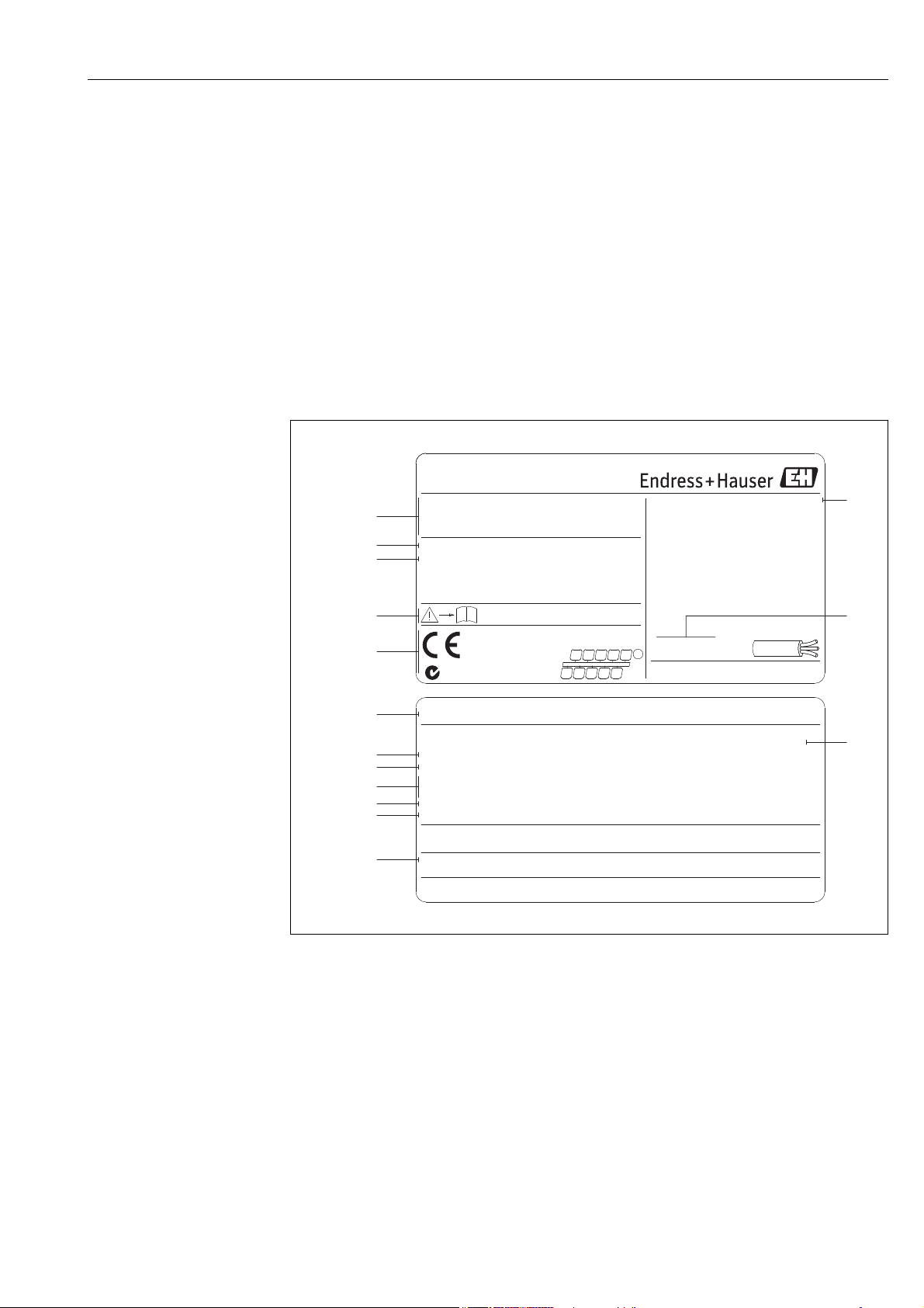
2.1.1 Nameplate of the transmitter/sensor
Fig. 1: Nameplate specifications for transmitter and sensor (example)
A = nameplate on transmitter, B = nameplate on sensor (only compact version)
1 Order code / serial number: see the specifications on the order confirmation for the meanings of the individual
letters and digits.
2 Power supply: 9 to 32 V DC, Power consumption: 1.2 W
3 PROFIBUS PA, Profile 3.0
4 Nominal diameter
5 Calibration factor
6 Material sensor and gasket
7 Medium temperature range
8Reserved for information on special products
9 Data regarding Pressure Equipment Directive (optional)
10 Permitted ambient temperature range
11 Degree of protection
Endress + Hauser 7
A0004806
2 Identification Proline Prowirl 72 PROFIBUS PA
ABCDEFGHJKLMNPQRST
TAG No.:
Ser.No.:
12345678901
Order Code:
Pat. US 4,743,837 US 6,003,384
i
IP67/NEMA/Type 4X
-40°C<Ta<+85°C
-40°F<Ta<+185°F
Gasket:
TM:
Graphite
-200°C...+400°C/-328°F...+752°F
72WXX-XXXXXXXXXXXX
K-factor:
1.0000 P/L
Materials:
CF3M/F316/F316L/1.4404, 316L
PROWIRL W
3.1
Size:
DN50
PED 97/23/EC: Cat. III
2007
N12895
pnom = PS = 10bar / ptest = 20bar
1
2
3
4
6
9
11
5
10
Meter Body:
25
7
8
Service date:
XXXXXXXXXXXSer.No.:
Exworks / ab Werk / réglages usine:
Date: 10.Jul 2008
XX.XX.XX
Device SW:
HART
Communication:
XXXXXXXDrivers:
Update2:
Update1:
1
2
3
4
5
6
7
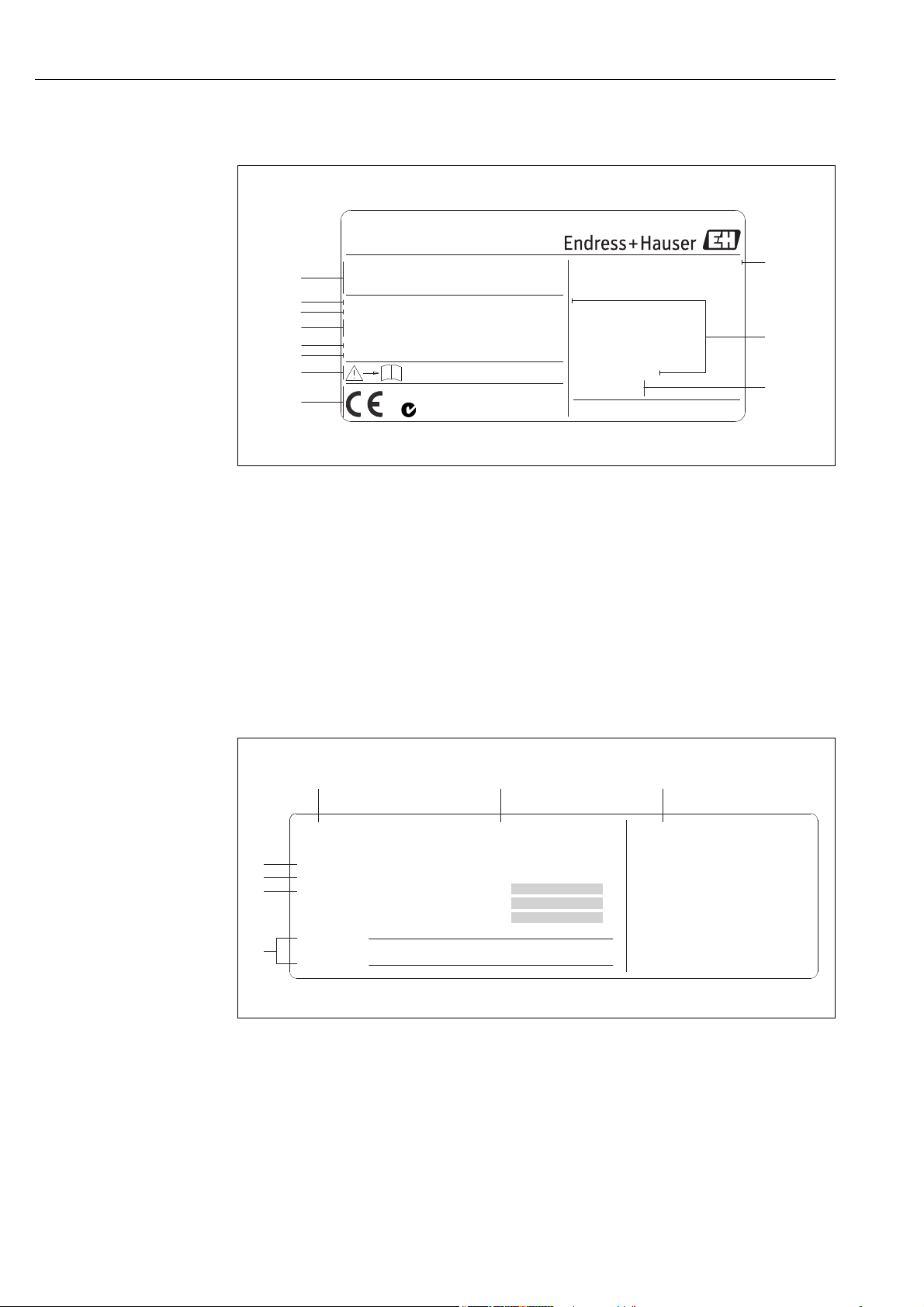
2.1.2 Nameplate of the sensor, remote version
a0001872
Fig. 2: Nameplate specifications for transmitter, remote version (example)
1 Order code / serial number: see the specifications on the order confirmation for the meanings of the individual
letters and digits.
2 Nominal diameter
3 Calibration factor
4 Material sensor and gasket
5 Medium temperature range
6Reserved for information on special products
7 Permitted ambient temperature range
8 Data regarding Pressure Equipment Directive (optional)
9 Degree of protection
2.1.3 Service nameplate
Fig. 3: Service nameplate specifications for transmitter (example)
1 Serial number
2 Date of manufacturing
8 Endress + Hauser
3 Service date
4 Device software
5 Type of device communication (e.g. PROFIBUS PA)
6 Revision number
7 Space for update entries
A0006761

Proline Prowirl 72 PROFIBUS PA 2 Identification
2.2 Certificates and approvals
The devices are designed according to good engineering practice to meet state-of-the-art safety
requirements, have been tested and left the factory in a condition in which they are safe to operate.
The devices comply with the applicable standards and regulations in accordance with EN 61010-1
"Protection Measures for Electrical Equipment for Measurement, Control, Regulation and
Laboratory Procedures" and the EMC requirements as per IEC/EN 61326.
The measuring system described in these Operating Instructions complies with the legal
requirements of the EU Directives. Endress+Hauser confirms this by affixing the CE mark to it and
by issuing the CE declaration of conformity.
The measuring system meets the EMC requirements of the "Australian Communications and Media
Authority (ACMA)".
2.3 Registered trademarks
GYLON
®
Registered trademark of Garlock Sealing Technologies, Palmyar, NY, USA
®
PROFIBUS
Registered trademark of PROFIBUS User Organization e.V., Karlsruhe, Germany
INCONEL
®
Registered trademark of Inco Alloys International Inc., Huntington, USA
KALREZ
®
, VITON
®
Registered trademarks of E.I. Du Pont de Nemours & Co., Wilmington, USA
Fieldcheck
®
, Applicator®, FieldCare
®
Registered or registration-pending trademarks of Endress+Hauser Flowtec AG, Reinach,
Switzerland
Endress + Hauser 9
3 Installation Proline Prowirl 72 PROFIBUS PA
3 Installation
3.1 Incoming acceptance, transport, storage
3.1.1 Incoming acceptance
On receipt of the goods, check the following points:
• Check the packaging and the contents for damage.
• Check the shipment, make sure nothing is missing and that the scope of supply matches your
order.
3.1.2 Transport
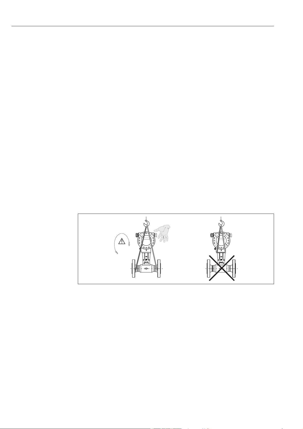
Please note the following when unpacking or transporting to the measuring point:
• The devices must be transported in the container supplied.
• Devices with nominal diameter DN 40 to 300 (1½ to 12") may not be lifted at the transmitter
housing or at the connection housing of the remote version when transporting (see Fig. 4). Use
carrier slings when transporting and put the slings around both process connections. Avoid chains
as these could damage the housing.
#
Warning!
Risk of injury if the measuring device slips.
The center of gravity of the entire measuring device might be higher than the points around which
the slings are slung. Therefore, when transporting, make sure that the device does not
unintentionally turn or slip.
A0001871
Fig. 4: Transportation instructions for sensors with DN 40 to 300 (1½ to 12")
3.1.3 Storage
Note the following points:
• Pack the measuring device in such a way as to protect it reliably against impact for storage (and
transportation). The original packaging provides optimum protection.
• The permissible storage temperature is:
– Standard: –40 to +80 °C (–40 to +176 °F)
– ATEX II 1/2 GD version/dust ignition-proof: –20 to +55 °C (–4 to +131 °F)
• When in storage, the device should not be exposed to direct sunlight in order to avoid
impermissibly high surface temperatures.
10 Endress + Hauser
Proline Prowirl 72 PROFIBUS PA 3 Installation
L
A
3.2 Installation conditions
Note the following points:
• The measuring device requires a fully developed flow profile as a prerequisite for correct volume
flow measurement. The inlet and outlet runs must be taken into account (see Page 14).
• The maximum permitted ambient temperatures (see Page 83) and fluid temperatures (see
Page 84) must be observed.
• Pay particular attention to the notes on orientation and piping insulation (see Page 12).
• Verify that the correct nominal diameter and pipe standard (DIN/JIS/ANSI) were taken into
account when ordering since the calibration of the device and the achievable accuracy depend on
these factors. If the mating pipe and the device have different nominal diameters/pipe standards,
an inlet correction can be made via the device software by entering the actual pipe diameter (see
MATING PIPE DIAMETER function on Page 115).
• The correct operation of the measuring system is not influenced by plant vibrations up to 1 g,
10 to 500 Hz.
• For mechanical reasons, and in order to protect the piping, it is advisable to support heavy sensors.
For weight information, please refer to Technical Information TI070D/06/en.
3.2.1 Dimensions
The dimensions and lengths of the sensor and transmitter can be found in the Technical Information
TI070D/06/en.
3.2.2 Installation location
We recommend you observe the following dimensions to guarantee problem-free access to the
device for service purposes:
• Minimum spacing (A) in all directions = 100 mm (3.94 inch)
• Necessary cable length (L): L + 150 mm (L + 5.91 inch).
A0001870
Fig. 5: A = Minimum spacing in all directions, L = cable length
Endress + Hauser 11

3 Installation Proline Prowirl 72 PROFIBUS PA
B
D
A
C
3.2.3 Orientation
The device can be installed basically in any orientation. Please consider the following, however
(Fig. 6):
• In the case of liquids, there should be upward flow in vertical pipes to avoid partial pipe filling (see
orientation A).
• The arrow on the meter body has to point in flow direction.
• In order to make sure that the maximum ambient temperature (see Page 83) is not exceeded, we
recommend the following orientations:
– In the case of hot fluids (e.g. steam or fluid temperature 200 °C/392 °F), select orientation
C or D.
– Orientations B and D are recommended for very cold fluids (e.g. liquid nitrogen).
Caution!
"
• If fluid temperature is 200 °C ( 392 °F), orientation B is not permitted for the wafer version
(Prowirl 72 W) with a nominal diameter of DN 100 (4") and DN 150 (6").
• In case of vertical orientation and downward flowing liquid, the piping has always to be
completely filled.
Fig. 6: Possible orientations of the device
High fluid temperature:
– horizontal piping: orientation C or D
– vertical piping: orientation A
Low fluid temperature:
– horizontal piping: orientation B or D
– vertical piping: orientation A
12 Endress + Hauser
A0001869
Proline Prowirl 72 PROFIBUS PA 3 Installation
12
Esc
E
-
+
Esc
E
-
+
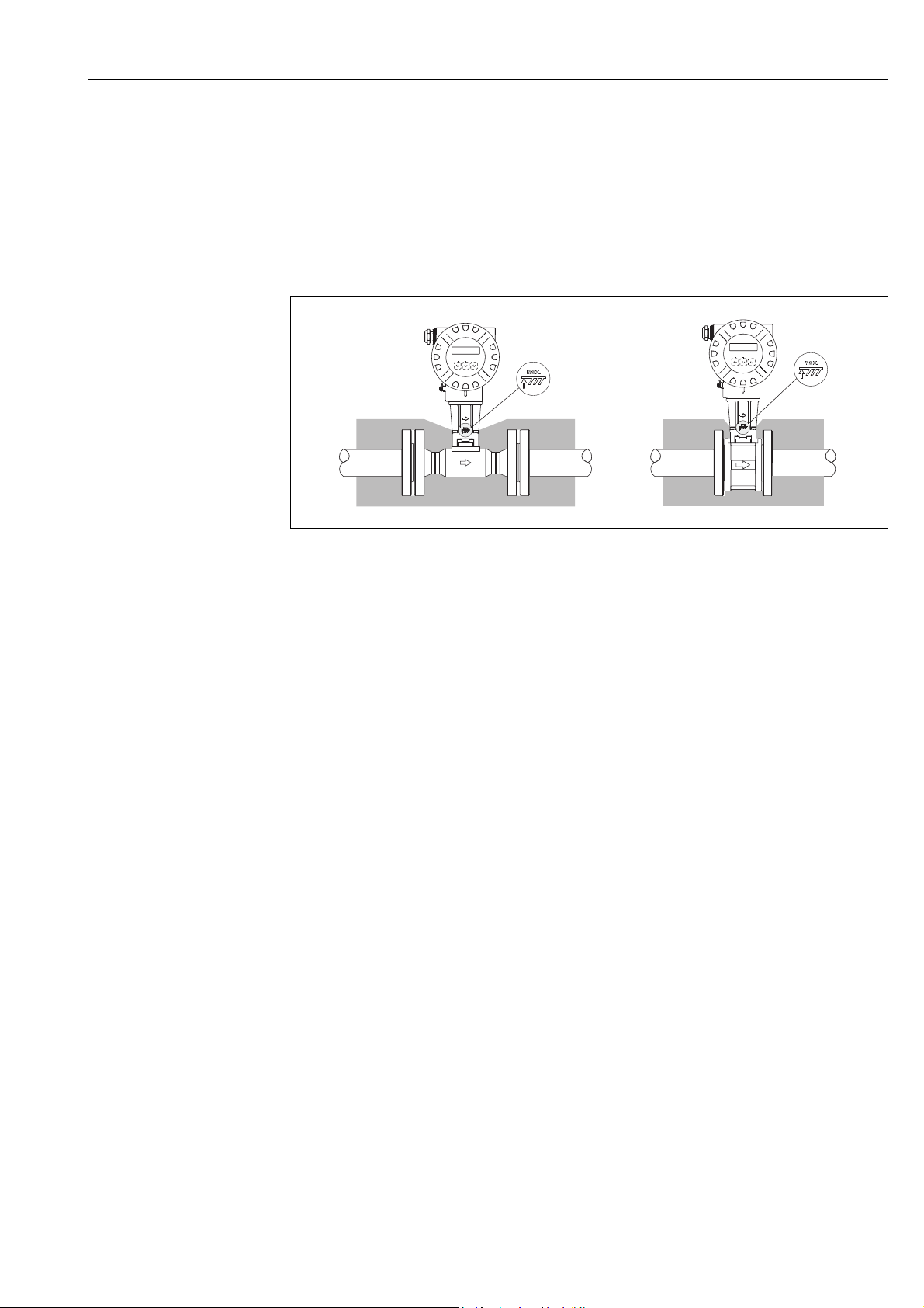
3.2.4 Heat insulation
Some fluids require suitable measures to avoid heat transfer at the sensor. A wide range of materials
can be used to provide the required insulation.
When insulating, please ensure that a sufficiently large area of the housing support is exposed. The
uncovered part serves as a radiator and protects the electronics from overheating (or undercooling).
The maximum insulation height permitted is illustrated in the Fig. 7. These apply equally to both
the compact version and the sensor in the remote version.
"
A0001868
Fig. 7: 1 = Flanged version, 2 = Wafer version
Caution!
Danger of electronics overheating!
• Therefore, make sure that the adapter between sensor and transmitter and the connection
housing of the remote version is always exposed.
• Note that a certain orientation might be required, depending on the fluid temperature Page 12.
• Information on permissible temperature ranges Page 83.
Endress + Hauser 13
3 Installation Proline Prowirl 72 PROFIBUS PA
15 x DN 5 x DN
A
1
3
5
2
4
6
A
A
A
A
A
B
B
B
B
B
B
17 x DN + 8 x h
5 x DN
20 x DN
5 x DN
40 x DN 5 x DN
25 x DN
5 x DN
50 x DN
5 x DN
h
PT
TT
3...5 x DN
4...8 x DN
Esc
E
-
+
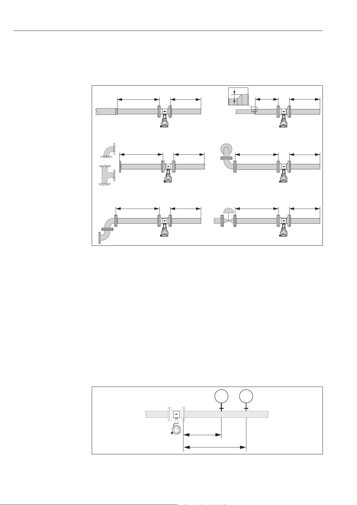
3.2.5 Inlet and outlet run
As a minimum, the inlet and outlet runs shown below must be observed to achieve the specific
accuracy of the device. The longest inlet run shown must be observed if two or more flow
disturbances are present.
A0001867
Fig. 8: Minimum inlet and outlet runs with various flow obstructions
A Inlet run
BOutlet run
1 = Reduction
2 = Expansion
3 = 90° elbow or T-piece
4 = 2 x 90° elbow, 3-dimensional
5 = 2 x 90° elbow
6 = Control valve
!
Note!
A specially designed perforated plate flow conditioner can be installed if it is not possible to observe
the inlet runs required (see Page 15).
Outlet runs with pressure and temperature measuring points
If pressure and temperature measuring points are installed after the device, please ensure there is a
large enough distance between the device and the measuring point so there are no negative effects
on vortex formation in the sensor.
14 Endress + Hauser
Fig. 9: Installation of pressure measuring point (PT) and temperature measuring point (TT)
A0003780
Proline Prowirl 72 PROFIBUS PA 3 Installation
8xDN
2xDN
5xDN
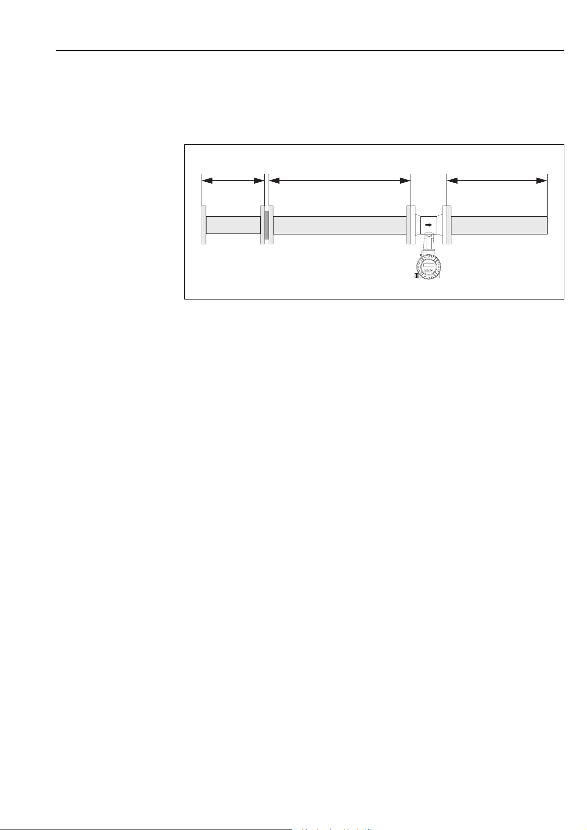
Perforated plate flow conditioner
A specially designed perforated plate flow conditioner, available from Endress+Hauser, can be
installed if it is not possible to observe the inlet runs required. The flow conditioner is fitted between
two piping flanges and centered with mounting bolts. Generally, this reduces the inlet run required
to 10 DN with complete accuracy.
A0001887
Fig. 10: Perforated plate flow conditioner
Calculation examples (SI units) for the pressure loss of flow conditioners:
The pressure loss for flow conditioners is calculated as follows:
p [mbar] = 0.0085 · [kg/m³] · v² [m/s]
• Example with steam
p = 10 bar abs
t = 240 °C = 4.39 kg/m³
v = 40 m/s
• Example with H
= 965 kg/m³
v = 2.5 m/s
p = 0.0085 · 965 · 2.5
O condensate (80°C)
2
= 51.3 mbar
p = 0.0085 · 4.39 · 40² = 59.7 mbar
3.2.6 Vibrations
The correct operation of the measuring system is not influenced by plant vibrations up to 1 g, 10 to
500 Hz. Consequently, the sensors require no special measures for attachment.
3.2.7 Limiting flow
See the information on Page 79 and 86.
Endress + Hauser 15
3 Installation Proline Prowirl 72 PROFIBUS PA
1
2
3
4
5
3.3 Installation
3.3.1 Mounting sensor
Caution!
"
Please note the following prior to mounting:
• Prior to installing the measuring device in the piping, remove all traces of transport packaging and
any protective covers from the sensor.
• Make sure that the internal diameters of seals are the same as, or greater than, those of the
measuring pipe and piping. Seals projecting into the flow current have a negative effect on the
vortex formation after the bluff body and cause inaccurate measurement. The gaskets provided
by Endress+Hauser for the wafer version have therefore an inner diameter with a bigger inner
diameter than the piping.
• Ensure that the arrow on the measuring pipe matches the direction of flow in the piping.
• Lengths:
– Prowirl W (wafer version): 65 mm (2.56 inch)
– Prowirl F (flanged version) See Technical Information TI070D/06/en.
Mounting Prowirl W
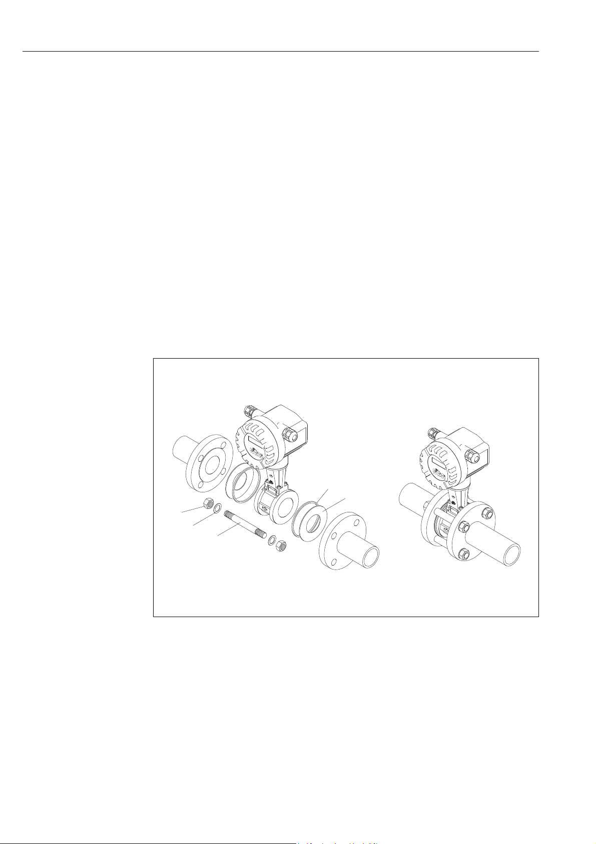
The centering rings supplied are used to mount and center the wafer-style devices.
A mounting kit consisting of tie rods, seals, nuts and washers can be ordered separately.
Fig. 11: Mounting the wafer version
1Nut
2Washer
3Tie rod
4 Centering ring (is supplied with the device)
5Seal
16 Endress + Hauser
A0001888
Proline Prowirl 72 PROFIBUS PA 3 Installation
180°
180°
4x45°
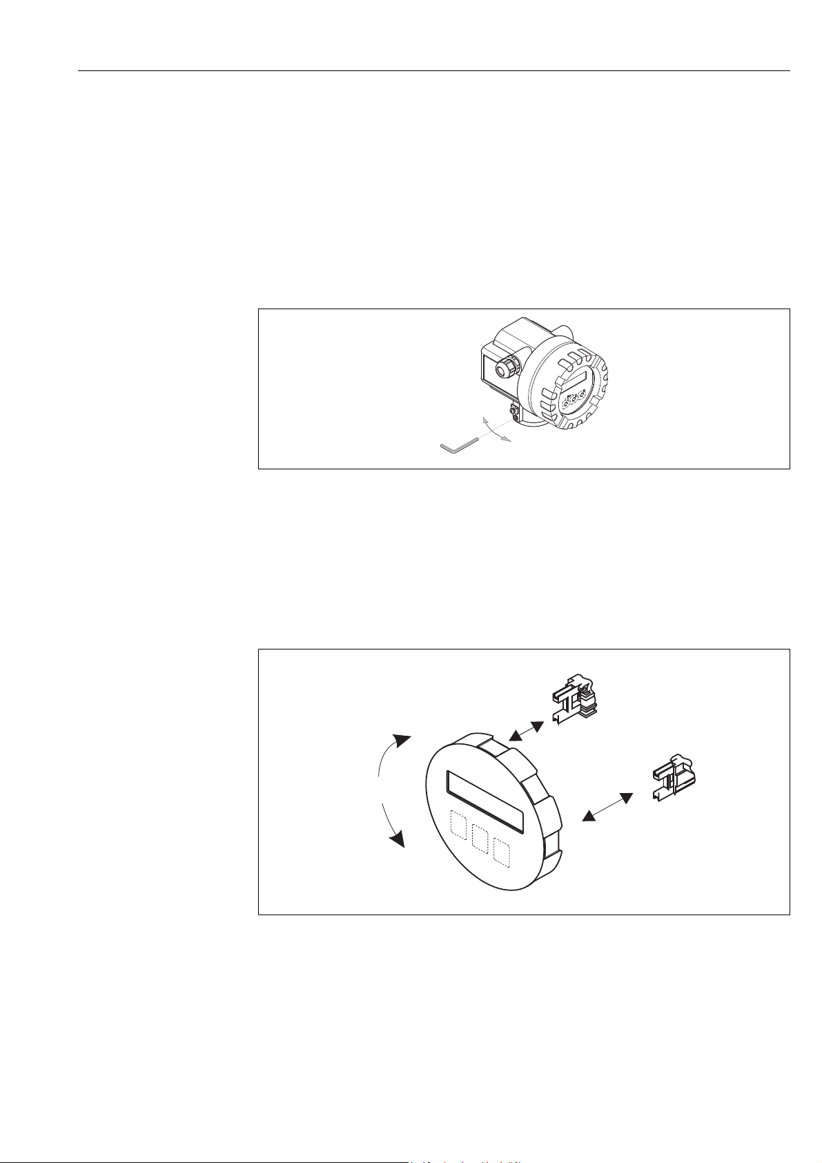
3.3.2 Rotating the transmitter housing
The electronics housing can be rotated continuously 360° on the housing support.
1. Loosen the safety screw.
2. Turn the transmitter housing to the desired position (max. 180° in each direction to the stop).
! Note!
There are recesses in the rotating groove at 90° stages (only compact version).
These help you align the transmitter easier.
3. Tighten the safety screw.
A0001889
Fig. 12: Rotating the transmitter housing
3.3.3 Rotating the local display
1. Unscrew the cover of the electronics compartment from the transmitter housing.
2. Remove the display module from the transmitter retainer rails.
3. Turn the display to the desired position (max. 4 45° in each direction) and reset it onto the
retaining rails.
4. Screw the cover of the electronics compartment firmly back onto the transmitter housing.
A0003237
Fig. 13: Rotating the local display
Endress + Hauser 17

3 Installation Proline Prowirl 72 PROFIBUS PA
ANSCHLUSSKLEMMEN - FIELD TERMINALS
ANSCHLUSSKLEMMEN - FIELD TERMINALS
A
B
220 / *214
215/ *209
(8.66 / *8.43)
(8.46 / *8.23)
mm (inch)
Ø 20…70
(Ø 0.79…2.75)
3.3.4 Mounting transmitter (remote)
The transmitter can be mounted in the following ways:
• Wall mounting
• Pipe mounting (with separate mounting kit, accessories Page 64)
The transmitter and the sensor must be mounted separate in the following circumstances:
• poor accessibility,
• lack of space,
• extreme ambient temperatures.
Caution!
"
If the device is mounted to warm piping, make certain that the housing temperature does not
exceed the max. permissible temperature value.
– Standard: –40 to +80 °C (–40 to +176 °F)
– EEx d/XP version: –40 to +60 °C (–40 to +140 °F)
– ATEX II 1/2 GD version/dust ignition-proof: –20 to +55 °C (–4 to +131 °F)
Mount the transmitter as illustrated in the diagram.
Fig. 14: Mounting the transmitter (remote version)
A Direct wall mounting
BPipe mounting
* Dimensions for version without local operation
A0003801
18 Endress + Hauser

Proline Prowirl 72 PROFIBUS PA 3 Installation
3.4 Post-installation check
Perform the following checks after installing the measuring device in the piping:
Device condition and specifications Notes
Is the device damaged (visual inspection)?
Do the process temperature/pressure, ambient temperature, measuring range
etc. correspond to the specifications of the device?
Installation Notes
Does the arrow on the pipe stand or on the sensor match the direction of flow
through the pipe?
Are the measuring point number and labeling correct (visual inspection)? –
Is the orientation chosen for the sensor correct, in other words suitable for
sensor type, fluid properties (outgassing, with entrained solids) and fluid
temperature?
Process environment / process conditions Notes
Is the measuring device protected against moisture and direct sunlight?
see Page 79 ff.
see Page 11 ff.
Endress + Hauser 19

4 Wiring Proline Prowirl 72 PROFIBUS PA
4 Wiring
#
Warning!
When connecting Ex-certified devices, please refer to the notes and diagrams in the Ex-specific
supplement to these Operating Instructions. Please do not hesitate to contact your Endress+Hauser
representative if you have any questions.
4.1 PROFIBUS PA cable specifications
Cable type
Twin-core cables are recommended for connecting the device to the fieldbus. Following IEC
61158-2 (MBP), four different cable types (A, B, C, D) can be used with the fieldbus, only two of
which (cable types A and B) are shielded.
• Cable types A or B are particularly preferable for new installations. Only these types have cable
shielding that guarantees adequate protection from electromagnetic interference and thus the
most reliable data transfer. In the case of multi-pair cables (type B), it is permissible to operate
multiple fieldbuses (with the same degree of protection) on one cable. No other circuits are
permissible in the same cable.
• Practical experience has shown that cable types C and D should not be used due to the lack of
shielding, since the freedom from interference generally does not meet the requirements
described in the standard.
The electrical data of the fieldbus cable have not been specified but determine important
characteristics of the design of the fieldbus, such as distances bridged, number of users,
electromagnetic compatibility, etc.
Type A Type B
Cable structure Twisted pair,
shielded
Wire size 0.8 mm
Loop-resistance (direct current) 44 /km 112 /km
Impedance at 31.25 kHz 100 ± 20% 100 ± 30%
Attenuation constant at 39 kHz 3 dB/km 5 dB/km
Capacitive asymmetry 2 nF/km 2 nF/km
Envelope delay distortion (7.9 to 39 kHz) 1.7 s/km *
Shield coverage 90% *
Max. cable length (inc. spurs >1 m (>3 ft)) 1900 m (6200 ft) 1200 m (4000 ft)
* Not specified
(AWG 18) 0.32 mm (AWG 22)
One or more twisted pairs, fully
shielded
Suitable fieldbus cables from various manufacturers for non-hazardous areas are listed below:
• Siemens: 6XV1 830-5BH10
• Belden: 3076F
• Kerpen: CeL-PE/OSCR/PVC/FRLA FB-02YS(ST)YFL
20 Endress + Hauser
Proline Prowirl 72 PROFIBUS PA 4 Wiring
Maximum overall cable length
The maximum network expansion depends on the type of protection and the cable specifications.
The overall cable length combines the length of the main cable and the length of all spurs (>1 m
(>3 ft)).
Note the following points:
• The maximum permissible overall cable length depends on the cable type used:
Type A 1900 m 6200 ft
Type B 1200 m 4000 ft
• If repeaters are used, the maximum permissible cable length is doubled.
A maximum of three repeaters are permitted between user and master.
Maximum spur length
The line between the distribution box and field device is described as a spur.
In the case of non-Ex applications, the max. length of a spur depends on the number of spurs (>1 m)
(>3 ft):
Number of spurs 1 to 12 13 to 14 15 to 18 19 to 24 25 to 32
Max. length per spur
[m] 120 90 60 30 1
[ft] 400 300 200 100 3
Number of field devices
In systems that meet FISCO in the EEx ia type of protection, the line length is limited to
max. 1000 m (3280 ft). A maximum of 32 users per segment in non-Ex areas or a maximum of
10 users in an Ex-area (EEx ia IIC) is possible. The actual number of users must be determined
during project planning.
Bus termination
The start and end of each fieldbus segment are always to be terminated with a bus terminator. With
various junction boxes (non-Ex), the bus termination can be activated via a switch. If this is not the
case, a separate bus terminator must be installed.
Note the following points:
• In the case of a branched bus segment, the device furthest from the segment coupler represents
the end of the bus.
• If the fieldbus is extended with a repeater then the extension must also be terminated at both
ends.
Further information
General information and further notes regarding the wiring can be found in the BA034S/04: "Field
communication PROFIBUS DP/PA: Guidelines for planning and commissioning".
Endress + Hauser 21

4 Wiring Proline Prowirl 72 PROFIBUS PA
4.1.1 Shielding and grounding
When planning the shielding and grounding for a fieldbus system, there are three important points
to consider:
• Electromagnetic compatibility (EMC)
• Explosion protection
• Safety of the personnel
To ensure the optimum electromagnetic compatibility of systems, it is important that the system
components and above all the cables, which connect the components, are shielded and that no
portion of the system is unshielded. Ideally, the cable shields will be connected to the field devices'
housings, which are usually metal. Since these are generally connected to the protective earth, the
shield of the bus cable is grounded many times. Make sure that the stripped and twisted lengths of
cable shield to the terminals are as short as possible.
This approach, which provides the best electromagnetic compatibility and personnel safety, can be
used without restriction in systems with good potential equalization.
In the case of systems without potential equalization, a power supply frequency (50 Hz) equalizing
current can flow between two grounding points which, in unfavorable cases, e.g. when it exceeds
the permissible shield current, may destroy the cable.
To suppress the low frequency equalizing currents on systems without potential equalization, it is
therefore recommended to connect the cable shield directly to the building ground (or protective
earth) at one end only and to use capacitive coupling to connect all other grounding points.
"
!
Caution!
The legal EMC requirements are met only when the cable shield is grounded at both ends!.
4.2 Connecting the remote version
4.2.1 Connecting the sensor
Note!
• The remote version must be grounded. In doing so, the sensor and transmitter must be connected
to the same potential matching.
• When using the remote version, always make sure that you connect the sensor only to the
transmitter with the same serial number. Compatibility errors (e.g. the incorrect K-factor will be
used) can occur if the devices are not connected in this way.
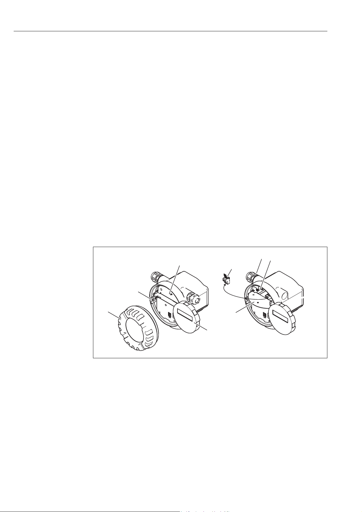
1. Remove the cover of the connection compartment of the transmitter (a).
2. Remove the cover of the connection compartment of the sensor (b).
3. Feed the connecting cable (c) through the appropriate cable entries.
4. Wire the connecting cable between the sensor and transmitter in accordance with the
electrical connection diagram:
Fig. 15
Wiring diagram in the screw caps
5. Tighten the glands of the cable entries on the sensor housing and transmitter housing.
6. Screw the cover of the connection compartment (a/b) back onto the sensor housing or
transmitter housing.
22 Endress + Hauser
Proline Prowirl 72 PROFIBUS PA 4 Wiring
a
c
b
d
3
3
1
1
4
4
2
2
55667
7
8
8
DIFF +
DIFF +
DIFF –
DIFF –
GROUND
GROUND
+5VA
+5VA
–5VA
–5VA
TEMP 1
TEMP 1
TEMP 2
TEMP 2
TEMP 3
TEMP 3
e
f
A0001893
Fig. 15: Connecting the remote version
a Connection compartment cover (transmitter)
b Connection compartment cover (sensor)
c Connecting cable (signal cable)
d Identical potential matching for sensor and transmitter
e Connect shielding to ground terminal in transmitter housing and keep as short as possible
f Connect shielding to cable strain relief clamp in connection housing
!
!
Wire color (colour code according to DIN 47100):
Terminal number: 1 = white; 2 = brown; 3 = green; 4 = yellow, 5 = gray; 6 = pink; 7 = blue; 8 = red
4.2.2 Cable specifications, standard connecting cable
The specifications of the cable connecting the transmitter and the sensor of the remote version are
as follows:
•4 2 0.5 mm
Note!
If the cross-section of a cable deviates from the specification, the value for the cable length has to
be calculated. See "Calculating and entering the cable length".
• Conductor resistance according to DIN VDE 0295 class 5 or IEC 60228 class 5: 39 /km
Note!
The conductor resistance specified by the standard is compensated for.
• Capacity core/screen: < 400 pF/m (< 122 pF/ft)
• Cable length: max. 30 m (98 ft)
• Operating temperature: –40 to +105 °C (–40 to +221 °F)
2
(AWG 20) PVC cable with common shield (4 pairs, pair-stranded).
Endress + Hauser 23

4 Wiring Proline Prowirl 72 PROFIBUS PA
4.2.3 Cable specifications, armored connecting cable
The optionally available armored connecting cable between transmitter and sensor possesses the
following specifications:
•4 2 0.5 mm
2
(AWG 20) PVC cable with common shield (4 pairs, pair-stranded).
!
!
!
Note!
If the cross-section of a cable deviates from the specification, the value for the cable length has to
be calculated. See "Calculating and entering the cable length".
• Conductor resistance according to DIN VDE 0295 class 5 or IEC 60228 class 5: 39 /km
Note!
The conductor resistance specified by the standard is compensated for.
• Extensively resistant against acids, bases and specific oils
• A galvanized braided steel wire forms the total shield
• Outer sheath version: smooth, uniform, round
• Cable length: max. 30 m (98 ft)
• Operating temperature: –30 to +70 °C (–22 to +158 °F)
Note!
The cable resistance specified as 39 /km in accordance with the standard, is compensated. If a
cable is used with a cable cross-section deviating from the specification, the value for the cable
length must be calculated as follows and entered in the CABLE LENGTH function ( Page 107).
Cable resistance of the
cable used [ /km]
Cable resistance
in accordance with specification
[/km]
Actual cable
length [m]
= cable length to be entered [m]
Example:
• Cable resistance of used cable = 26 /km
• Cable resistance as per specification = 39 /km
• Actual cable length = 15 m
26 /km
39 /km
Conclusion:
In the CABLE LENGTH function ( Page 107) the value 10 m (32.81 ft), depending on the unit
selected in the UNIT LENGTH function, must be entered.
15 m = 10 m
24 Endress + Hauser

Proline Prowirl 72 PROFIBUS PA 4 Wiring
4.3 Connecting the measuring unit
4.3.1 Connecting the transmitter
!
"
Note!
• When connecting Ex-certified devices, please refer to the notes and diagrams in the Ex-specific
supplement to these Operating Instructions.
• The remote version must be grounded. In doing so, the sensor and transmitter must be connected
to the same potential equalization.
• The national regulations governing the installation of electrical equipment must be observed.
• When connecting the transmitter, use a connecting cable with a continuous service temperature
of at least –40 °C (–40 °F) to permitted max. ambient temperature plus 10 °C (plus 18 °F).
• A shielded cable must be used for the connection.
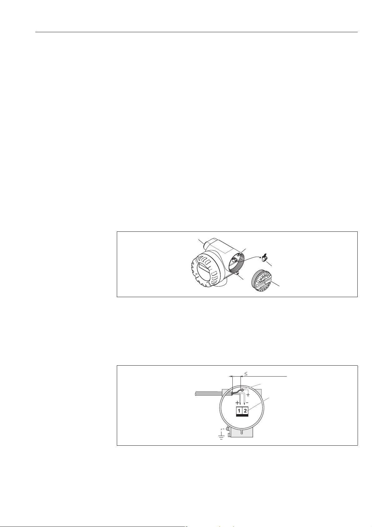
• The terminals for the PROFIBUS PA connection (terminal 1 = PA+, terminal 2 = PA –) have
integrated reverse polarity protection. This ensures correct signal transmission via the fieldbus
even if lines are confused.
• Cable cross-section: max. 2.5 mm²
• Observe the grounding concept.
Caution!
• Risk of damaging the PROFIBUS cable!
If the shielding of the cable is grounded at more than one point in systems without additional
potential equalization, power supply frequency equalization currents can occur that damage the
cable or the shielding. In such cases the shielding of the cable is to be grounded on only one side,
i.e. it must not be connected to the ground terminal of the housing. The shield that is not
connected should be insulated!
• We recommend that the PROFIBUS not be looped using conventional cable glands. If you later
replace even just one measuring device, the bus communication will have to be interrupted.
Endress + Hauser 25
4 Wiring Proline Prowirl 72 PROFIBUS PA
e
f
d
a
c
b
d
g
Connecting the transmitter, non-Ex / Ex i/IS and Ex n version ( Fig. 16)
1. Unscrew the cover (a) of the electronics compartment from the transmitter housing.
2. Remove the display module (b) from the retaining rails (c) and refit onto right retaining rail with
the left side (this secures the display module).
3. Loosen screw (d) of the cover of the connection compartment and fold down the cover.
4. Push the power supply/PROFIBUS cable through the cable gland (e).
5. Tighten the cable glands (e) (see also Page 30).
6. Pull the terminal connector (f) out of the transmitter housing and connect the power
supply/PROFIBUS cable ( Fig. 18).
! Note!
The terminal connector (d) is pluggable, i.e. it can be plugged out of the transmitter housing
to connect the cable.
7. Plug the terminal connector (f) into the transmitter housing.
8. Secure the ground cable to the ground terminal (g).
! Note!
Between the stripped PROFIBUS cable and the ground terminal, the cable shielding should not
exceed a length of 5 mm (0.20 inch).
9. Only remote version:
Secure ground cable to the ground terminal ( Fig. 18, B).
10. Fold up the cover of the connection compartment and tighten the screws (d).
11. Remove the display module (b) and fit on the retaining rails (c).
12. Screw the cover of the electronics compartment (a) onto the transmitter housing.
Fig. 16: Procedure when connecting the transmitter, non-Ex/Ex i/IS and Ex n version
a Cover of electronics compartment
b Display module
c Retaining rail for display module
d Connection compartment cover
e Cable gland
f Terminal connector
g Ground terminal
a0003782
26 Endress + Hauser
Proline Prowirl 72 PROFIBUS PA 4 Wiring
b
a
c
d
e
A
D
+
–
12
B
C
5mm(0.20 in)
aaaaaaaaaaaaaaaaaaaaa
aaaaaaaaaaaaaaaaaaaaa
aaaaaaaaaaaaaaaaaaaaa
aaaaaaaaaaaaaaaaaaaaa
aaaaaaaaaaaaaaaaaaaaa
aaaaaaaaaaaaaaaaaaaaa
aaaaaaaaaaaaaaaaaaaaa
aaaaaaaaaaaaaaaaaaaaa
aaaaaaaaaaaaaaaaaaaaa
aaaaaaaaaaaaaaaaaaaaa
aaaaaaaaaaaaaaaaaaaaa
aaaaaaaaaaaaaaaaaaaaa
aaaaaaaaaaaaaaaaaaaaa
aaaaaaaaaaaaaaaaaaaaa
aaaaaaaaaaaaaaaaaaaaa
aaaaaaaaaaaaaaaaaaaaa
aaaaaaaaaaaaaaaaaaaaa
aaaaaaaaaaaaaaaaaaaaa
aaaaaaaaaaaaaaaaaaaaa
aaaaaaaaaaaaaaaaaaaaa
aaaaaaaaaaaaaaaaaaaaa
aaaaaaaaaaaaaaaaaaaaa
aaaaaaaaaaaaaaaaaaaaa
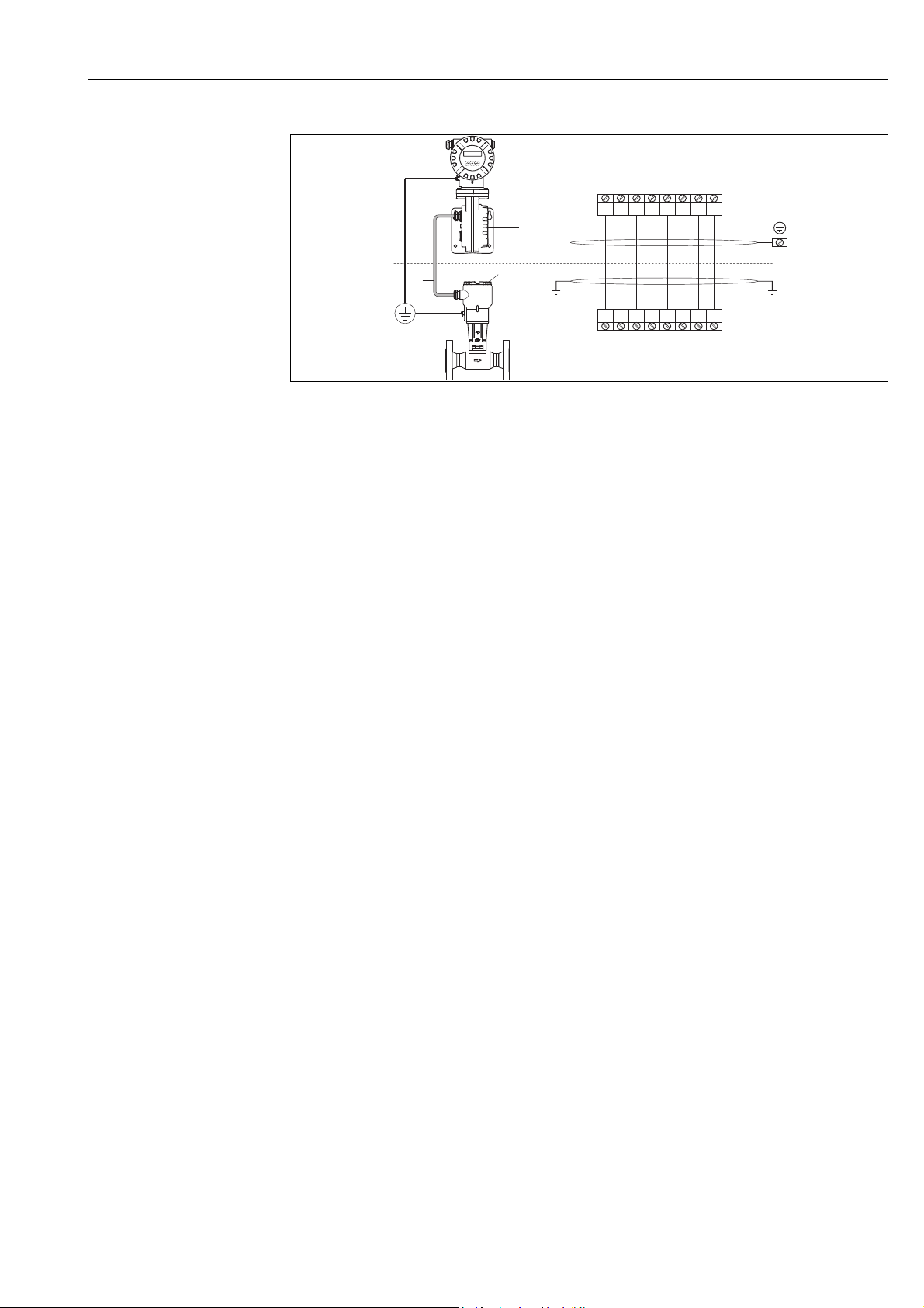
Connecting the transmitter, Ex d/XP version ( Fig. 17)
1. Release the securing clamp (a) of the connection compartment cover.
2. Screw the connection compartment cover (b) off the transmitter housing.
3. Push the power supply/PROFIBUS cable through the cable gland (c).
4. Tighten the cable glands (c) (see also Page 30).
5. Pull the terminal connector (d) out of the transmitter housing and connect the power
supply/PROFIBUS cable (see Fig. 18).
! Note!
The terminal connector (d) is pluggable, i.e. it can be plugged out of the transmitter housing
to connect the cable.
6. Plug the terminal connector (d) into the transmitter housing.
7. Secure the ground cable to the ground terminal (g).
! Note!
Between the stripped PROFIBUS cable and the ground terminal, the cable shielding should not
exceed a length of 5 mm (0.20 inch).
8. Only remote version:
Secure ground cable to the ground terminal (see Fig. 18, B).
9. Screw the connection compartment cover (b) onto the transmitter housing.
10. Tighten the securing clamp (a) of the connection compartment cover.
Fig. 17: Procedure when connecting the transmitter, Ex d/XP version
a Securing clamp for connection compartment cover
b Connection compartment cover
c Cable gland
d Terminal connector
e Ground terminal
Wiring diagram
Fig. 18: Connecting the transmitter
A PROFIBUS cable
B Ground terminal (between the stripped PROFIBUS cable and the ground terminal, the cable shielding should not
exceed a length of 5 mm (0.20 inch)).
C Terminal connector (1 = PA +; 2 = PA –)
D Ground terminal (external, only relevant for remote version)
Endress + Hauser 27
a0003783
a0003784

4 Wiring Proline Prowirl 72 PROFIBUS PA
4.3.2 Terminal assignment
Terminal no. (inputs/outputs)
Order version 1 2
72***-***********H PA + PA –
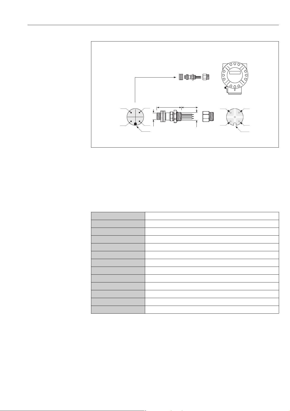
4.3.3 Fieldbus connector
The connection technology of PROFIBUS PA allows measuring devices to be connected
to the fieldbus via uniform mechanical connections such as T-boxes, distribution modules, etc.
This connection technology using prefabricated distribution modules and plug-in connectors offers
substantial advantages over conventional wiring:
• Field devices can be removed, replaced or added at any time during normal operation.
Communication is not interrupted.
• Installation and maintenance are significantly easier.
• Existing cable infrastructures can be used and expanded instantly, e.g. when constructing new
star distributors using 4-channel or 8-channel distribution modules.
The device can therefore be supplied with the option of a ready-mounted fieldbus connector.
Fieldbus connectors for retrofitting can be ordered from Endress+Hauser as a spare part (see
Page 73).
Supply line/T-box shielding
Use cable glands with good EMC properties, if possible with all-round contact of the cable shielding
(Iris spring). This requires small differences in potential, poss. potential equalization.
• The PA cable shielding must be intact.
• The shielding connection must always be kept as short as possible.
Ideally, cable glands with Iris springs should be used for the shielding connection. The shielding is
positioned on the T-box housing by means of the Iris spring located inside the gland. The shielding
braid is located beneath the Iris spring. When the armored thread is tightened, the Iris spring is
pressed against the shielding, thereby creating a conductive connection between the shielding and
the metal housing.
A connection box or a plug-in connection is to be seen as part of the shielding (Faraday shield). This
applies, in particular, to remote boxes if these are connected to a PROFIBUS PA measuring device
by means of a pluggable cable. In such instances, a metallic connector must be used where the cable
shielding is positioned at the plug housing (e.g. prefabricated cables).
28 Endress + Hauser
Proline Prowirl 72 PROFIBUS PA 4 Wiring
150/300 mm
45.0 mm
(1.766")
PG 13.5
M12x1
BC D
4
1
2
E
3
34
21
F
5
6
7
A
a0003859
Fig. 19: Connectors for connecting to the PROFIBUS PA
A Aluminum field housing
B Protection cap for connector
C Fieldbus connector
D Adapter PG 13.5 / M 20.5
E Connector at housing (male)
F Female connector
Pin assignment / color codes:
1 Brown wire: PA+ (terminal 1)
2Not connected
3 Blue wire: PA – (terminal 2)
4 Black wire: ground
5 Middle female connector not assigned
6 Positioning groove
7 Positioning key
Technical data (connector):
Connection cross section 0.75 mm
Connector thread PG 13.5
Degree of protection IP 67 in accordance with DIN 40 050 IEC 529
Contact surface CuZnAu
Housing material Cu Zn, surface Ni
Flammability V - 2 in accordance with UL - 94
Operating temperature –40 to +85 °C, (–40 to +185 °F)
Ambient temperature range –40 to +150 °C, (–40 to +302 °F)
Nominal current per contact 3 A
Nominal voltage 125 to 150 V DC in accordance with the VDE Standard 01 10/ISO Group 10
Resistance to tracking KC 600
Volume resistance 8 m in accordance with IEC 512 Part 2
Insulation resistance 1012 in accordance with IEC 512 Part 2
2
Endress + Hauser 29
4 Wiring Proline Prowirl 72 PROFIBUS PA
ab
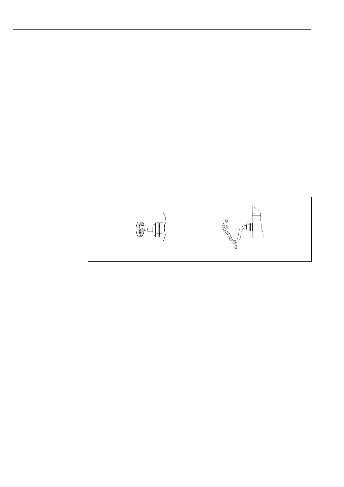
4.4 Degree of protection
The measuring device meets all the requirements for IP 67 (NEMA 4X).
Caution!
"
Do not loosen the screws of the sensor housing, as otherwise the degree of protection guaranteed
by Endress+Hauser no longer applies.
Compliance with the following points is mandatory following installation in the field or servicing in
order to ensure that IP 67 (NEMA 4X) protection is maintained:
• The housing seals must be clean and undamaged when inserted into their grooves. The seals must
be dried, cleaned or replaced if necessary.
• The housing screws and screw caps must be firmly tightened.
• The cables used for connection must be of the specified outside diameter Page 81, cable
entries.
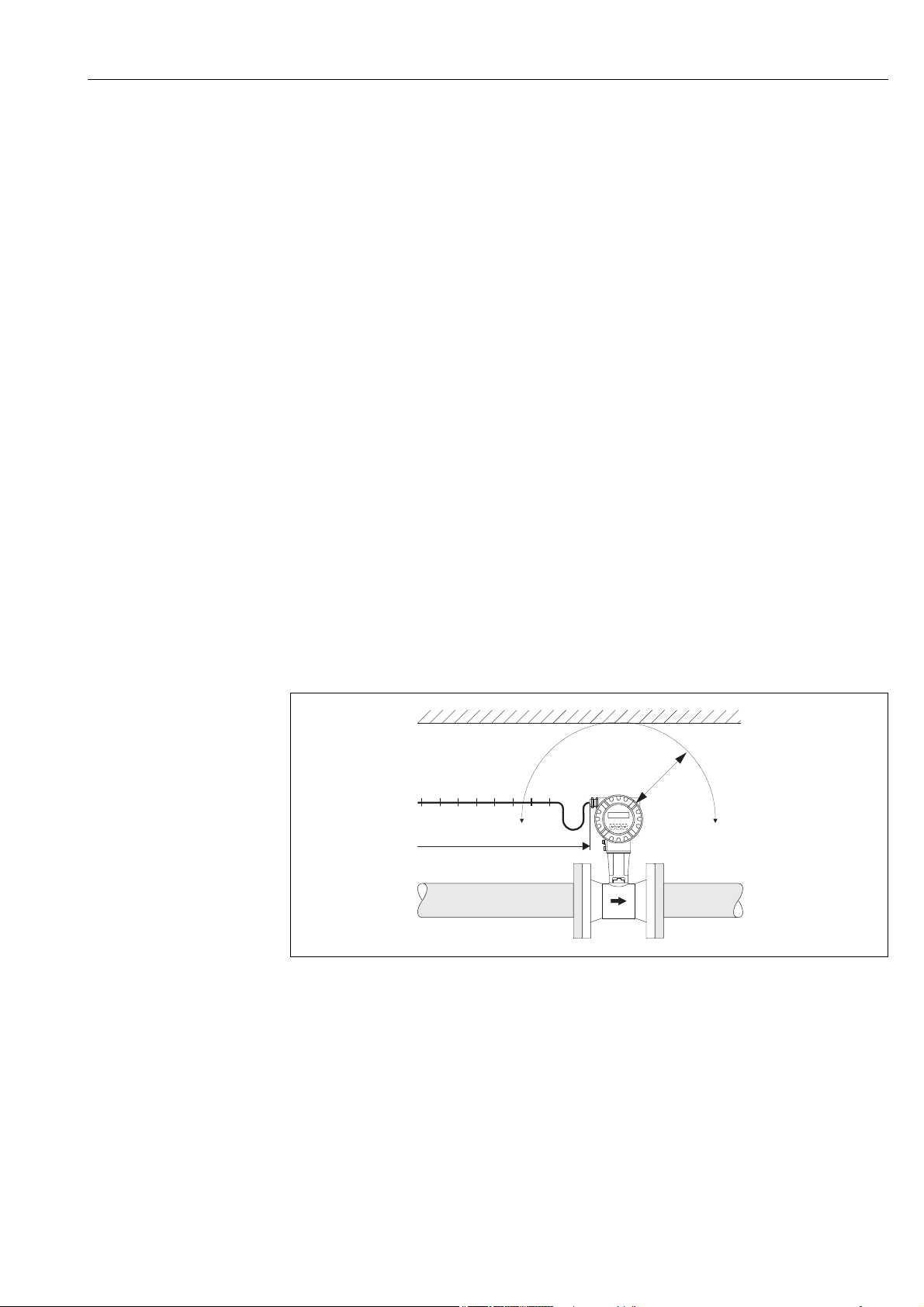
• The cable entries must be firmly tightened (point a Fig. 20).
• The cable must loop down before it enters the cable entry ("water trap") (point b Fig. 20).
This arrangement prevents moisture penetrating the entry.
The cable entries should not point upwards.
• Replace all unused cable entries with dummy plugs.
• Do not remove the grommet from the cable entry.
Fig. 20: Installation instructions for cable entries
a0001914
30 Endress + Hauser
Loading...